1
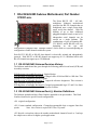
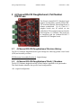
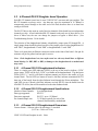
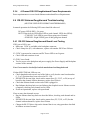
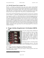
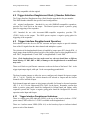
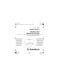
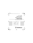
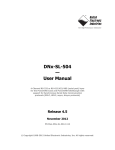
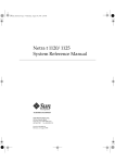
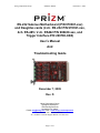
Moog Components Group
Submux1 Manual
December 7, 2009
RS-232 Submux Motherboard (P/N 970381-xxx)
and Daughter-cards (4 ch. RS-232 P/N 970391-xxx,
4ch. RS-485 / 2 ch. RS422 P/N 980430-xxx, and
Trigger Interface P/N 200700-XXX)
User’s Manual
And
Troubleshooting Guide
December 7, 2009
Rev. D
Moog Components Group
Springfield Operations
750 West Sproul Road
Springfield, PA 19064
E-Mail: [email protected] URL: www.moog.com/components
Tel: 610-328-4000 Fax 610-605-6216
24/7 Technical Customer Support Hotline: 610-605-6101
Page 1 of 19
Moog Components Group
Submux1 Manual
1
December 7, 2009
RS-232/422/485 Submux Motherboard, Part Number 970381-xxx. ...................................................... 3
1.1 RS-232/422/485 Submux Revision History: .................................................................................... 3
1.2 RS-232/422/485 Submux Dash (-) Number Definitions .................................................................. 3
1.3 Manual Revision History: ................................................................................................................ 4
1.4 RS-232/422/485 Submux Motherboard Operation: ......................................................................... 4
1.4.1
RS-232/422/485 Submux Indicators: ...................................................................................... 4
1.4.2
RS-232/422/485 Submux Motherboard Specifications: .......................................................... 5
1.4.3
RS-232/422/485 Submux Dimensions: ................................................................................... 5
1.4.4
RS-232/422/485 Submux Power Requirements: ..................................................................... 5
1.5 Submux Motherboard Troubleshooting ........................................................................................... 5
1.5.1
Submux Motherboard Board Level Testing ........................................................................... 5
1.5.2
Submux Motherboard Data Loop-Back Test .......................................................................... 6
1.5.3
RS-232 Driver Chip Channel Selection .................................................................................. 7
1.5.4
Test Data Channels ................................................................................................................. 7
2
4-Channel RS-232 Daughterboard, Part Number 970391-xxx ................................................................ 8
2.1 4-Channel RS-232 Daughterboard Revision History ....................................................................... 8
2.2 4-Channel RS-232 Daughterboard Dash (-) Numbers ..................................................................... 8
2.3 4-Channel RS-232 Daughter board Operation: ................................................................................ 9
2.3.1
4-Channel RS-232 Daughterboard Indicators:........................................................................ 9
2.3.2
4-Channel RS-232 Daughterboard Specifications: ................................................................. 9
2.3.3
4-Channel RS-232 Daughterboard Dimensions:..................................................................... 9
2.3.4
4-Channel RS-232 Daughterboard Power Requirements: .....................................................10
2.4 RS-232 Submux Daughtercard Troubleshooting ............................................................................10
2.4.1
RS-232 Submux Daughtercard Board Level Testing ............................................................10
2.4.2
RS-232 Daughterboard Data Loop-back Test........................................................................11
2.4.3
RS-232 Driver Chip Channel Selection .................................................................................11
3
4-Channel RS-485 / 2-Channel RS-422 Daughterboard, Part Number 980430-xxx...............................12
3.1 4-Channel RS-485 Daughterboard Revision History: .....................................................................12
3.2 4-Channel RS-485 Daughterboard Dash (-) Number Definitions: ..................................................12
3.3 4-Channel RS-485 Daughterboard Operation: ................................................................................13
3.3.1
Setting RS-485 Data Rates ....................................................................................................13
3.3.2
Selecting RS-422 ...................................................................................................................13
3.3.3
4-Channel RS-485 Daughterboard Indicators:.......................................................................13
3.3.4
4-Channel RS-485 Daughterboard Specifications: ................................................................14
3.3.5
4-Channel RS-485 Daughterboard Dimensions:....................................................................14
3.3.6
4-Channel RS-485 Daughterboard Power Requirements: .....................................................14
3.4 RS-485/RS-422 Submux Daughterboard Troubleshooting .............................................................14
3.4.1
Board Level Testing ..............................................................................................................15
3.4.2
RS-485 Channel Data Test ....................................................................................................15
3.4.3
RS-422 Channel Data Loopback Test ...................................................................................16
4
Trigger Interface Daughtercard, Part Number 200700-xxx. .................................................................16
4.1 Trigger Interface Daughtercard Revision History: ..........................................................................16
4.2 Trigger Interface Daughtercard Dash (-) Number Definitions ........................................................17
4.3 Trigger Interface Daughter board Operation: ..................................................................................17
4.3.1
Trigger Interface Daughtercard Indicators: ...........................................................................17
4.3.2
Trigger Interface Daughterboard Specifications: ...................................................................18
4.3.3
Trigger interface Daughterboard Dimensions: ......................................................................18
4.3.4
Trigger Interface Daughterboard Power Requirements: ........................................................18
4.4 Trigger Interface Daughtercard Troubleshooting ............................................................................18
4.4.1
Trigger Interface Daughtercard Board Level Testing ............................................................18
Page 2 of 19
Moog Components Group
Submux1 Manual
December 7, 2009
1 RS-232/422/485 Submux Motherboard, Part Number
970381-xxx.
The Prizm RS-232 /422 / 485 Submultiplexer (Submux) motherboard
provides four RS-232 channels that are
multiplexed onto a single Prizm highspeed serial data channel. With the
addition of up to three additional
pluggable daughter boards, a total of 16
independent serial channels can be
carried on a single Submux. The
combinations of types of channels (RS232, RS-422, and/or RS-485) will vary
depending
on
the
type
and
configuration of daughter cards. Multiple Submux’s can be used on a system depending on
configuration of other channels within the system.
Each RS-232, RS-422 or RS-485 data channel is electrically isolated and independently
powered. Each RS-232 or RS-485 channel can support up to 115.4 Kilobaud while each
RS-422 channel can support up to 230 Kilobaud
1.1 RS-232/422/485 Submux Revision History:
The Submux motherboard has gone through the following printed circuit board (PCB) and
Assembly revisions:
PCB Revision A/Assembly Revision A Original design
PCB Revision A/Assembly Revision B Changed value of R44 and R46 to 10K ohm. This
revision is fully compatible with the original.
PCB Revision A/Assembly Revision C Improved reference designators. This revision is
fully compatible with prior revisions.
PCB Revision A/Assembly Revision D Changed programmable logic U3 and U4 to faster
parts. This revision is fully compatible with prior revisions.
1.2 RS-232/422/485 Submux Dash (-) Number Definitions
The Submux motherboard has a Dash Number appended to the part number. This Dash
Number identifies the specific board configurations:
-001 original configuration.
-002 Current standard configuration. Changed programmable logic to support faster bus
speeds.
Note: this version is required for Video 3 Systems.
-003 Special version that reduces the number motherboard channels from 4 to 2 and ups
the sample rate to allow for higher speed applications.
Page 3 of 19
Moog Components Group
Submux1 Manual
December 7, 2009
1.3 Manual Revision History:
The manual has gone through the following revisions:
Revision A
Revision B
Revision C
Revision D
Original design
4/19/01 Added in Trigger Interface Section
2/24/09 Updated contact information to reflect Moog Components Group
12/7/09 Updated 980430 section about -002 dash number
1.4 RS-232/422/485 Submux Motherboard Operation:
On VIDEO 3 systems, the submux mother board is connected to the PRIZM fiber optic
modem via the backplane. On older VIDEO1 and VIDEO 2 systems, the Submux is
connected to the Prizm fiber optic multiplexer either directly through the backplane or
optionally it may be connected via ribbon cable to a Video board. On the systems that
utilize the ribbon cable, if the Submux is connected to Video Board #1 in the surface unit,
it’s companion Submux board set must be connected to Video Board #1 in the sub-sea unit.
There are four green three pin Phoenix connectors on the on the front of the submux
motherboard; the top pin is for transmitted data (TXD), the bottom pin for received data
(RXD) and the middle pin for signal ground (GND).
1.4.1 RS-232/422/485 Submux Indicators:
There is a single green LED indicator (LED1) at the top of the board to indicate +5VDC
power status. LED1 will be lit if +5VDC is available. The status of the high-speed data
channel is indicated by a dual green LED indicator (LED2) which is the second row of
LEDs from the top of the board. The left LED indicates the receive link status (RLINK)
from the Prizm multiplexer. If this LED is lit, the Submux board is receiving both RX clock
and RX data from the multiplexer. The right LED indicates the transmit link status
(TLINK) to the Prizm multiplexer. If this LED is lit, the Submux board is receiving the TX
clock and is generating TX data. Both LEDs on LED2 must be lit before sub-multiplexed
data will travel through the Prizm multiplexer to the other Submux board (and vice versa).
Once both LEDs on LED2 are lit, the data channels are active. The dual green LEDs (LED3,
4, 5, and 6) will flash to indicate transmit and receive data traffic on a per channel basis. For
each of the channels, the left LED indicates activity on the TXD pin and the right LED
indicates activity on the RXD pin.
Note: Sometimes the flashing may be to fast to see and the LED may appear to be on all
the time.
Note: Since the data channels are electrically isolated from each other and from the
Prizm multiplexer DC ground, testing of the channels with an oscilloscope or meter
requires that the appropriate channel ground wire be attached to the test equipment's
ground.
Page 4 of 19
Moog Components Group
Submux1 Manual
December 7, 2009
1.4.2 RS-232/422/485 Submux Motherboard Specifications:
Number of data Channels:
Data type supported:
Data rates supported:
Per channel sample rate:
4 on Motherboard (RS-232 only), up to 16 channels total
with 3 daughtercards in place
RS-232, RS-422, and RS-485
RS-232 - up to 115 Kbaud
RS-485 - up to 115 Kbaud
RS-422 - up to 230 Kbaud
4.5 Msps(typical) for each of the 16 ch. on the –002 boards
3.125 Msps(typical) for each of the 16 ch. on the –001 boards
1.4.3 RS-232/422/485 Submux Dimensions:
VME 3-U format - 100 mm wide x 160 mm long x 20 mm thick (3.937 x 6.299 x 0.80 in)
VME 3-U PCB and faceplate in rack: 20 mm wide x 128 mm high (0.8 in x 5.05 in)
1.4.4 RS-232/422/485 Submux Power Requirements:
+5 Volts at 0.65 Amps (3.25 Watts)
1.5 Submux Motherboard Troubleshooting
In normal operation the following LED status should be observed:
+5VDC power LED (LED1) – Lit green
LINK LED (dual LED2)
left RLINK LED - Lit green if receiving link from Modem
right TLINK LED - Lit green transmitting link to Modem
RS-232 Data Activity LEDs (dual LED on each channel, LED3 thru LED6):
-- TXD LED - Left LED lit green if data going out of channel
-- RXD LED - Right LED lit green if data going into channel
1.5.1 Submux Motherboard Board Level Testing
If DC power LED is out:
• Make sure 5VDC is available at the backplane connector.
• Check 2Amp fuse (F1) with ohmmeter, replace with another PICO fuse if blown.
If + 5VDC is measured at connector and DC Power LED is not lit green:
• Check LED and transistor circuit
If +5VDC is not found:
• Test for power at the backplane and power supply (See Power Supply and Backplane
sections of the manual).
• Replace board
If the TLINK LED (right LED) is out:
Page 5 of 19
Moog Components Group
•
•
Submux1 Manual
December 7, 2009
If +5VDC power is available, TLINK LED should be always lit. LED will be off for
a fraction of a second after board is plugged in.
Replace board
If the RLINK LED (left LED) is out:
• Check that local Modem board is plugged in
• Check that Submux board at other end of link is plugged in.
• Check that the multiplexer on the remote end is operating by checking the Modem’s
DATA and FIBER LEDs.
• Run the Submux data loop back test described below, checking each channel and its
LEDs
• If still not operational, replace with spare board
If the RLINK and all the RXD/TXD LEDs are flickering:
• Check for high link error rate which will cause the Modem’s DATA LED to flicker
and cause the Modem’s ERR LED to flicker or light solid
If high data link errors are noted:
• Check the fiber optic cable and all connections
• Replace the Modem with a spare
If either RXD/TXD link LEDs are out:
If RXD LED does not light, check surface mount fuse (F2, F3, F4, or F5) for that
channel with an ohmmeter, replace fuse if blown
• Check that Submux board at other end of link is plugged in
• Run Submux data loop back test (see Submux data loopback test in Submux section
of manual), checking each channel and its LEDs
• If still not operational, replace with spare board
•
If one or more data channels are out:
• Run the Submux data loop back test described below, checking each channel and its
LEDs
• If RXD LED does not light, check surface mount fuse (F2, F3, F4, or F5) for that
channel with an ohmmeter, replace fuse if blown
• Change the RS-232 driver chip channel on the channel that is out, using procedure
described below in section 1.4.3
• Replace board with spare.
If no spare is available:
• Move data connector to a spare working channel, if available
1.5.2 Submux Motherboard Data Loop-Back Test
With a Submux or Submux and RS232 daughterboard in both the ROV and surface units,
run RS-232 data into pins 1 and 3 of the connector of the channel being tested. The RS-232
data can be input into either the ROV or surface Submux. On the other end of the link, short
pins 1 and 3 of the Submux channel being tested. This will allow the two Submux boards to
Page 6 of 19
Moog Components Group
Submux1 Manual
December 7, 2009
talk to each other in loopback. Both RX and TX LEDs on both boards should be lit and/or
flickering. If any of the LEDs are not operating check one of the other channels. If the
LEDs operate on that channel, replace Submux with a spare board or use the working
channels only.
1.5.3 RS-232 Driver Chip Channel Selection
The RS-232 driver chip used on each of the four channels of this board has two
independent drivers per chip. As each individual RS-232 channel needs only one of these
drivers, the four 3-position jumpers allow for the selection of one of the two drivers. If a
driver is blown out, the user can change the jumpers to bypass the failed driver. For
example, on channel 1 of the Submux motherboard JP29, JP30, JP31, JP32 control the
selection of the driver. (See Submux motherboard jumper configuration for details.) Call
Prizm for technical assistance if you have any questions about this procedure.
1.5.4 Test Data Channels
If an appropriate serial data test generator is available (or a PC with Communications
software, or even a square wave generator) the individual channels can be tested on a
channel-by-channel basis. This test can be done for all channels on the motherboard and all
daughterboards. The user must be sure that the test signal levels are compatible with the
interface/channel being tested.
Page 7 of 19
Moog Components Group
Submux1 Manual
December 7, 2009
2 4-Channel RS-232 Daughterboard, Part Number
970391-xxx
The Prizm 4-channel RS-232 Daughter board
supports 4 independent, optically isolated RS232 serial data channels, when plugged onto a
Submux motherboard. Up to a total of 3
daughter boards may be stacked on one
motherboard. The maximum data rate that this
board supports is 115Kbaud. This board can
be intermixed with the 4-channel RS-485/ 2
channel RS-422 Daughter board.
2.1
4-Channel RS-232 Daughterboard Revision History
The RS-232 Submux daughterboard has gone through the following printed circuit board
(PCB) and Assembly revisions:
PCB Revision A/Assembly Revision A Original design
2.2
4-Channel RS-232 Daughterboard Dash (-) Numbers
The RS-232 Submux daughterboard has a Dash Number appended to the part number.
This Dash Number identifies the specific board configurations:
-001 original configuration.
Page 8 of 19
Moog Components Group
Submux1 Manual
December 7, 2009
2.3 4-Channel RS-232 Daughter board Operation:
Each RS-232 channel circuit has it's own 5VDC DC-DC converter and opto-couplers. The
RS-232 channels are always active. Any data rate, up to the maximum of 115 Kbaud, is
transparently passed through to the other end of the link, therefore there is no baud rate
setting to deal with.
The RS-232 driver chip used on each of the four channels of this board has two independent
channels per chip. As each individual RS-232 channel needs only one of these drivers, if a
driver is blown out, the user can change the jumpers to bypass a failed driver. (See
Troubleshooting Section 2.4 for details)
The selection of the daughterboard identity is handled by jumper posts JP1 though JP8. A
single jumper shunt should be placed on each of the jumper posts to select daughterboard #1
with “DB1”, daughterboard #2 with “DB2” or daughterboard #3 with “DB3”.
There are 4 green three pin Phoenix connectors on the on the front of the board. One pin for
transmit, one pin for ground, and one pin for receive.
Note: Each daughterboard set (one surface and one sub-sea) should have a different
board identity (i.e. DB1, DB2 or DB3) or damage to the daughterboards or motherboard
may result.
2.3.1
4-Channel RS-232 Daughterboard Indicators:
There is a single green LED indicator (LED5) at the top of the board to indicate +5VDC
power status; LED5 will be lit if +5VDC is available on the daughterboard. The dual green
LEDs (LED1, 2, 3 and 4) will flash to indicate transmit and receive data traffic on a per
channel basis. The left LED (or bottom if board is laid flat) indicates transmitted RS-232
data (out of the board) from the other Submux board through the Prizm multiplexer. The
right LED (or top if board is laid flat) indicates received RS-232 (into the board from the
local RS-232 device) that will be transferred to the other Submux board.
2.3.2
4-Channel RS-232 Daughterboard Specifications:
Number of data Channels:
Data type supported:
Data rates supported:
Per channel sample rate:
2.3.3
4 per daughterboard
RS-232
RS-232 - up to 115 Kbaud
3.125 Msps typically for each of the
channels, determined by motherboard
4-Channel RS-232 Daughterboard Dimensions:
Custom format - 100 mm wide x 86 mm long x 13 mm thick
(3.937 in x 3.40 in x 0.50 in )
VME 3-U PCB and faceplate in rack: None
Page 9 of 19
Moog Components Group
2.3.4
Submux1 Manual
December 7, 2009
4-Channel RS-232 Daughterboard Power Requirements:
Power requirements are covered under Submux motherboard Power Requirements.
2.4 RS-232 Submux Daughtercard Troubleshooting
(MUST BE USED WITH SUBMUX MOTHERBOARD)
In normal operation the following LED status should be observed:
DC power LED (LED5) – Lit green
RS-232 Data Activity LEDs (dual LED on each channel, LED1 thru LED4):
-- TXD LED - Left LED lit green if data going out of channel
-- RXD LED - Right LED lit green if data going into channel
2.4.1 RS-232 Submux Daughtercard Board Level Testing
If DC power LED is out:
• Make sure 5VDC is available at the backplane connector.
• Check 2Amp fuse (F1) with ohmmeter, replace with another PICO fuse if blown.
If + 5VDC is measured at connector and DC Power LED is not lit green:
• Check LED and transistor circuit
If +5VDC is not found:
• Test for power at the backplane and power supply (See Power Supply and Backplane
sections of the manual).
Note: Power must be checked for both the motherboard and daughterboard.
If either RXD/TXD link LEDs are out:
• Check daughterboards on each end of the link to verify that the same board number
(1, 2 or 3) positions have been selected at JP1 - JP8.
• If RXD LED does not light, check surface mount fuse (F1, F2, F3, or F4) on top of
board for that channel with an ohmmeter, replace fuse if blown
• Check that Submux board at other end of link is plugged in
• Run Submux data loop back test (see Submux data loopback test in Submux section
of manual), checking each channel and its LEDs
• If still not operational, replace with spare board
If one or more data channels are out:
Run the Submux data loop back test described below, checking each channel and its
LEDs.
• If RXD LED does not light, check surface mount fuse (F2, F3, F4, or F5) for that
channel with an ohmmeter, replace fuse if blown
• Change the RS-232 driver chip on the channel that is out, using procedure described
in Submux section of manual
•
Page 10 of 19
Moog Components Group
•
Submux1 Manual
December 7, 2009
Replace board with spare
If no spare is available:
• Move data connector to a spare working channel, if available
2.4.2 RS-232 Daughterboard Data Loop-back Test
With a Submux or Submux and RS232 daughterboard in both the ROV and surface units,
run RS-232 data into pins 1 and 3 of the connector of the channel being tested. The RS-232
data can be input into either the ROV or surface Submux. On the other end of the link, short
pins 1 and 3 of the Submux channel being tested. This will allow the two Submux boards to
talk to each other in loopback. Both RX and TX LEDs on both boards should be lit and/or
flickering. If any of the LEDs are not operating check one of the other channels. If the
LEDs operate on that channel, replace Submux with a spare board or use the working
channels only.
2.4.3 RS-232 Driver Chip Channel Selection
The RS-232 driver chip used on each of the four channels of this board has two independent
drivers per chip. As each individual RS-232 channel needs only one of these drivers, the
four 3-position jumpers allow for the selection of one of the two drivers. If a driver is blown
out, the user can change the jumpers to bypass the failed driver. For example, on channel 1
of the Submux motherboard JP29, JP30, JP31, JP32 control the selection of the driver. (See
Submux motherboard jumper configuration for details.) Call Prizm for technical assistance
if you have any questions about this procedure.
Page 11 of 19
Moog Components Group
3
Submux1 Manual
December 7, 2009
4-Channel RS-485 / 2-Channel RS-422
Daughterboard, Part Number 980430-xxx
The Prizm 4-channel RS-485
Daughterboard
supports
4
independent half-duplex (Two
way communication, but only one
way at a time) RS-485 serial data
channels or 2 full-duplex RS-422
channels when plugged onto a
Submux motherboard. Up to a
total of 3 daughterboards may be
stacked on one motherboard. This
board can be intermixed with the
4-channel RS-232 Daughterboard
or even used to convert RS-232 to
RS-485 in blocks of 4 channels.
The
4-channel
RS-485
Daughterboard
has
four
independent optically isolated
serial channels. The maximum
data rate that this board supports
for RS-485 is 115 Kbaud. Each RS-422 channel can support up to 230 kilobaud.
For simplicity this board will be referred to as the “4-Channel RS-485 Board” in subsequent
paragraphs.
3.1
4-Channel RS-485 Daughterboard Revision History:
The RS-485 Submux daughterboard has gone through the following printed circuit board
(PCB) and Assembly revisions:
PCB Revision A Original design.
PCB Revision B Corrected circuitry to include ECN’s against the Rev A PCB.
3.2
4-Channel RS-485 Daughterboard Dash (-) Number
Definitions:
The RS-485 Submux daughterboard has a Dash Number appended to the part number.
This Dash Number identifies the specific board configurations:
-001A to -001D original configuration.
-002D changed resistor values for R78, R79, R80 and R81 to correct a timing issue.
Page 12 of 19
Moog Components Group
3.3
Submux1 Manual
December 7, 2009
4-Channel RS-485 Daughterboard Operation:
Jumpers can be set on the daughterboard to select one or two channels of RS-422. (See
Jumper Configuration) Each RS-485 channel circuit has it's own 5VDC DC-DC converter
and optocouplers. As RS-422 requires twice as many connections as RS-485 (a pair for
receive and a pair for transmit), the second RS-485 channel (and the forth RS-485 channel if
two RS-422 channels are selected) is disabled when RS-422 is enabled.
To simplify RS-485 operation, the daughterboard is factory configured in “autobaud” mode
by selecting 57.6Kbaud (JP10 for channel 1, JP13 for channel 2, JP17 for channel 3, and
JP20 for channel 4). This mode will support the vast majority of applications.
Note: Call Prizm for help with specific settings or equipment.
The selection of the daughterboard identity is handled by jumper posts JP1 though JP8. A
single jumper shunt should be placed on each of the jumper posts to select daughterboard #1
with “DB1”, daughterboard #2 with “DB2” or daughterboard #3 with “DB3”.
Note: Each daughterboard set (one surface and one sub-sea) should have a different
board identity (i.e. DB1, DB2 or DB3of channels or damage to the daughterboards or
motherboard may result.
There are 4 gray or black three-pin Phoenix connectors on the front of the board, each with
one pin for transmit, one pin for ground, and one pin for receive.
3.3.1 Setting RS-485 Data Rates
This function has been factory pre-set to automatically accommodate any data rate from
300 baud up to and including 57.6Kbaud. To change or verify factory selection, refer to
the RS-485/422 Submux Daughter Board jumper configuration table in this manual.
3.3.2 Selecting RS-422
Jumpers allow RS-485 channels 1 and 2 (or 3 and 4) to be turned into 4-wire full duplex
RS-422 channels. (See jumper configuration table)
When RS-422 is selected:
- Channel 1 (or 3) becomes RS-422 receive (RX) channel
- Channel 2 (or 4) becomes RS-422 transmit (TX) channel
3.3.3
4-Channel RS-485 Daughterboard Indicators:
There is a single green LED indicator (LED1) at the top of the board to indicate +5VDC
power status; LED1 will be lit if +5VDC is available on the daughterboard. The dual green
LEDs (LED3, 5, 7 and 9) will flash to indicate transmit and receive data traffic on a per
channel basis. The left LED (or bottom if board is laid flat) indicates transmitted RSPage 13 of 19
Moog Components Group
Submux1 Manual
December 7, 2009
485/422 data (out of the board) from the other Submux board through the Prizm
multiplexer. The right LED (or top if board is laid flat) indicates received RS-485/422 (into
the board from the local RS-485/422 device) that will be transferred to the other Submux
board.
The single red surface mounted LED on the top side of the Daughterboard, in the middle of
each channel (LED2, 4, 6, and 8) will be lit whenever the RS-485 receiver is enabled.
3.3.4
4-Channel RS-485 Daughterboard Specifications:
Number of data
Channels:
Data type supported:
Data rates supported:
Per channel sample rate:
3.3.5
4 per daughterboard
4 channels of RS-485 or
2 channels of RS-422 or
2 RS-485 and 1 RS-422
RS-485 - up to 115 Kbaud
RS-422 - up to 230 Kbaud
3.125 Msps typically for each of the
channels, determined by motherboard
4-Channel RS-485 Daughterboard Dimensions:
Custom format - 100 mm wide x 86 mm long x 13 mm thick
(3.937 in x 3.40 in x 0.50 in )
VME 3-U PCB and faceplate in rack: None
3.3.6
4-Channel RS-485 Daughterboard Power Requirements:
Power requirements are covered under Submux motherboard Power Requirements.
3.4 RS-485/RS-422 Submux Daughterboard Troubleshooting
(MUST BE USED WITH SUBMUX MOTHERBOARD)
In normal operation the following LED status should be observed:
DC power LED (LED1) – Lit green
Front panel RS-485 Data Activity LEDs
(dual LED on each channel, LED3, LED5, LED7, LED9):
-- TXD LED - Left LED lit green if data going out of channel
-- RXD LED - Right LED lit green if data going into channel
Center of board RS-485 Receive Active LEDs
(single red surface mount LED2, LED4, LED6, LED8):
red LED - lit red if channel in receive mode,
may flash with data traffic
Front panel RS-422 Data Activity LEDs (channels 1 and 3 only):
-- Channel 1- RXD/TXD LEDs - Lit green if RS-422 traffic on channel 1
Page 14 of 19
Moog Components Group
Submux1 Manual
December 7, 2009
-- Channel 3- RXD/TXD LEDs - Lit green if RS-422 traffic on channel 2
NOTE: Channel 2 and 4 RXD/TXD LEDs will not be lit.
- No baud rate settings are required at any rate up to 256Kbaud
3.4.1 Board Level Testing
If DC power LED is out:
• Make sure 5VDC is available at the backplane connector.
• Check power connector and wiring to both rack power supplies.
If + 5VDC is measured at connector and DC Power LED is not lit green:
• Check LED and transistor circuit
If 5VDC is not found:
• Test for power at the backplane and power supply (See Power Supply and Backplane
sections of the manual).
Note: Power must be checked for both the motherboard and daughterboard.
If either RX/TX link LEDs are out:
• Check daughterboards on each h end of the link to verify that the same board number
(1, 2 or 3) positions have been selected at JP1 - JP8.
• If RXD LED does not light, check surface mount fuse (F1, F2, F3, or F4) on bottom
of board for that channel with an ohmmeter, replace fuse if blown
• Check that Submux board at other end of link is plugged in
• Run RS-232 CHANNEL DATA TEST or RS-422 CHANNEL DATA LOOP BACK
TEST below as appropriate, checking each channel and its LEDs
• If still not operational, replace with spare board
3.4.2 RS-485 Channel Data Test
RS-485 is a half-duplex communication process and requires a host computer running RS485 software at one end and a slave RS-485 device at the other end to test a data channel.
First verify that the host computer and slave RS-485 device will communicate correctly
when direct connected with cable between the host and slave. There will be only two
transmit/receive signals (RT+ and RT-). The voltage levels for RS-485 are 0 to 5VDC
(differential TTL). Then you can test a Prizm RS-485 channel.
With a Submux and RS-485/422 daughterboard in both the ROV and surface units and the
appropriate channel configured for RS-485, run RS-485 data into the channel to be tested.
The RS-485 data can be input into either the ROV or surface Submux. The host computer
should be able to communicate with the slave device with no errors. Both RX and TX
LEDs on both boards should be lit and/or flickering whenever the computers are talking. If
any of the LEDs are not operating check one of the other channels. If the LEDs operate on
that channel, replace RS-485 daughterboard and/or Submux motherboard with a spare board
or use the working channels only.
Page 15 of 19
Moog Components Group
Submux1 Manual
December 7, 2009
3.4.3 RS-422 Channel Data Loopback Test
RS-422 is a full-duplex communication process and a host computer running RS-422
software at one end can either communicate with itself (loopback mode) or with another RS422 computer at the other end to test a data channel. There will be two transmit signals (T+
and T-) and two receive signals (R+ and R-). The voltage levels for RS-422 are 0 to 5VDC
(differential TTL). First verify that the host computer will communicate correctly when
directly connected with a loopback cable. Then you can test a Prizm RS-422 channel.
With a Submux and RS-422 daughterboard in both the ROV and surface units, run RS-422
data into channels 1 or 3 [PIN1(R+), PIN2(GND), PIN3(R-)] and monitor the transmit data
from channels 2 or 4 [PIN1(T+), PIN2(GND), PIN3(T-)] of the RS-422 daughterboard to be
tested. The RS-422 data can be input into either the ROV or surface RS-422 daughterboard.
On the other end of the link, short channels 1 (J3) to 2 (J4) (J3-1 to J4-1, J3-2 to J4-2 and J33 to J4-3) or channels 3 (J5) to 4 (J6) (J5-1 to J6-1, J5-2 to J6-2 and J5-3 to J6-3). This will
allow the two RS-422 daughterboards to talk to each other in loop back. The host computer
should be able to communicate with itself with no errors. Both RX and TX LEDs on both
boards should be lit and/or flickering. If any of the LEDs are not operating check the other
channel. If the LEDs operate on that channel, replace RS-422 daughter board and/or
Submux motherboard with a spare board or use the working channel if one of the two
channels is operating.
4 Trigger Interface Daughtercard, Part Number 200700xxx.
The Prizm Trigger Interface Daughtercard
provides four channels of Input or Output
selectable interface for use with most
Acoustic Responder channels. This board
is meant for use as a daughter-card on the
standard PRIZM Submux1 or Submux2
motherboard. Refer to the Submux1 or
Submux II manual for a description of those
particular cards and the standard data
daughtercards.
Each trigger channel is electrically isolated
and independently powered. The board
contains jumper selections for Input/Output as well as Normal/Invert for both Input and
Output signals.
4.1 Trigger Interface Daughtercard Revision History:
The Trigger Interface Daughtercard has gone through the following printed circuit board
(PCB) and Assembly revisions:
PCB Revision A/Assembly Revision A Original design
Page 16 of 19
Moog Components Group
Submux1 Manual
December 7, 2009
on is fully compatible with the original.
4.2 Trigger Interface Daughtercard Dash (-) Number Definitions
The Trigger Interface Daughtercard has a Dash Number appended to the part number.
This Dash Number identifies the specific board configurations:
-001 original configuration. Intended for use with SIMRAD-compatible responders,
provides for 15volt levels on the output. The Simrad system requires a positive going
pulse for triggering of the responder.
-002 Intended for use with Accusonic/ORE-comptible responders, provides TTL
(5VDC) levels on the output. The ORE system requires a negative going pulse for
triggering of the responder.
4.3 Trigger Interface Daughter board Operation:
Each channel circuit has it's own DC-DC converter and opto-couplers to provide isolation
from of the I/O signals from the other channels and multiplexer system.
The selection of the daughterboard identity is handled by jumper posts JP13 though JP20. A
single jumper shunt should be placed on each of the jumper posts to select daughterboard #1
with “DB1”, daughterboard #2 with “DB2” or daughterboard #3 with “DB3”.
Note: Each daughterboard set (one surface and one sub-sea) should have a different
board identity (i.e. DB1, DB2 or DB3) or damage to the daughterboards or motherboard
may result.
There are 4 black two pin Phoenix connectors on the on the front of the board. Pin 1 is the
trigger input/output signal, while pin 2 is the corresponding ground/shield.
The board contains jumpers to allow the user to configure each channel for input or output
(JP1 4, 7 & 10). Typically the vehicle channels will selected as Output and the Surface
channels will be selected as Input.
Each channels input and output are also jumper selectable for Normal or Inverted operation
(JP2, 5, 8 & 11 for the Output and JP3,6,9 &12 for the Input). Responder systems that
utilize a positive going pulse should be configured for Normal Input and Output, while
responder systems that require a negative going pulse should be configured for Inverted
operation on the Input and Output.
4.3.1
Trigger Interface Daughtercard Indicators:
There is a single green LED indicator (LED5) at the top of the board to indicate +5VDC
power status; LED5 will be lit if +5VDC is available on the daughterboard.
There are 4 surface mount LEDS (LEDs 6–9) on the board top layer to indicate isolated
power to each of the channels.
Page 17 of 19
Moog Components Group
Submux1 Manual
December 7, 2009
The dual green LEDs (LED1, 2, 3 and 4) associated with each channel will flash to indicate
Input and Output traffic on a per channel basis. The left LED (or bottom if board is laid flat)
indicates an input signal is present while the right LED (or top if board is laid flat) indicates
an output signal is present.
4.3.2
Trigger Interface Daughterboard Specifications:
Number of data Channels:
Data type supported:
Data rates supported:
Per channel sample rate:
4.3.3
4 per daughterboard
Trigger Responder Pulse
N/A
3.125 Msps typically for each of the
channels, determined by motherboard
Trigger interface Daughterboard Dimensions:
Custom format - 100 mm wide x 86 mm long x 13 mm thick
(3.937 in x 3.40 in x 0.50 in )
VME 3-U PCB and faceplate in rack: None
4.3.4
Trigger Interface Daughterboard Power Requirements:
The Trigger Interface utilizes approximately 500mA @ 5VDC.
4.4 Trigger Interface Daughtercard Troubleshooting
(MUST BE USED WITH SUBMUX MOTHERBOARD)
In normal operation the following LED status should be observed:
DC power LED (LED5) – Lit green
Trigger I/O Data Activity LEDs (dual LED on each channel, LED1 thru LED4):
-- Input LED - Left LED lit green if data going into of channel
-- Output LED - Right LED lit green if data going out of channel
4.4.1 Trigger Interface Daughtercard Board Level Testing
POWER RELATED
If DC power LED is out to both the Motherboard and Daughtercard:
• Make sure 5VDC is available at the backplane connector.
• Check 2Amp fuse (F1) on Motherboard with ohmmeter, replace with another PICO
fuse if blown.
If the Motherboard has power but the Daughtercard DC Power LED is not lit:
• Verify +5VDC at the motherboard to daughter-card transmit and receive headers (J4
and J5) on the motherboard
• Check Power LED on the daughtercard.
Page 18 of 19
Moog Components Group
Submux1 Manual
December 7, 2009
If the Daughtercard Power LED (LED5) is on, but channels do not seem to be working:
• Verify that the individual channel Power LEDs (LED6-9) are lit
• If they are not, check the fuse for each channel (F1-F4)
• Verify the actual power to each channel by measuring the isolated power for each
channel at C2,4,8 & 10 (Power should be in +15VDC+/-10%)
SIGNAL RELATED (assumes all Power Related Items checked out OK)
If either the local Input or remote Output LED are not lighting when input signal is
applied:
• Verify the input signal is present with a scope.
• Check daughterboards on each end of the link to verify that the same board number
(1, 2 or 3) positions have been selected at JP13 – JP20.
• Verify that no other daughtercard on the motherboard stack is addressed as the same
daughtercard.
• Check that Submux board at other end of link is plugged in
• Run Submux motherboard data loop back test (see Submux data loopback test in
Submux section of manual), checking each channel and its LEDs to verify the
Submux motherboard is working
• If still not operational, replace with spare board
If no spare is available:
• Move data connector to a spare working channel, if available.
Page 19 of 19