1
Copyright E Sony/Tektronix Corporation. 1994. All rights reserved.
Copyright E Tektronix, Inc. 1994. All rights reserved.
Tektronix products are covered by U.S. and foreign patents, issued and pending. Information in this publication supercedes
that in all previously published material. Specifications and price change privileges reserved.
Printed in Japan.
Sony/Tektronix Corporation, P.O. Box 5209, Tokyo Int’l, Tokyo 100–31 Japan
Tektronix, Inc., P.O. Box 1000, Wilsonville, OR 97070–1000
TEKTRONIX and TEK are registered trademarks of Tektronix, Inc.
WARRANTY
Tektronix warrants that this product will be free from defects in materials and workmanship for a period of one (1) year
from the date of shipment. If any such product proves defective during this warranty period, Tektronix, at its option, either
will repair the defective product without charge for parts and labor, or will provide a replacement in exchange for the
defective product.
In order to obtain service under this warranty, Customer must notify Tektronix of the defect before the expiration of the
warranty period and make suitable arrangements for the performance of service. Customer shall be responsible for
packaging and shipping the defective product to the service center designated by Tektronix, with shipping charges prepaid.
Tektronix shall pay for the return of the product to Customer if the shipment is to a location within the country in which the
Tektronix service center is located. Customer shall be responsible for paying all shipping charges, duties, taxes, and any
other charges for products returned to any other locations.
This warranty shall not apply to any defect, failure or damage caused by improper use or improper or inadequate
maintenance and care. Tektronix shall not be obligated to furnish service under this warranty a) to repair damage resulting
from attempts by personnel other than Tektronix representatives to install, repair or service the product; b) to repair
damage resulting from improper use or connection to incompatible equipment; or c) to service a product that has been
modified or integrated with other products when the effect of such modification or integration increases the time or
difficulty of servicing the product.
THIS WARRANTY IS GIVEN BY TEKTRONIX WITH RESPECT TO THIS PRODUCT IN LIEU OF ANY
OTHER WARRANTIES, EXPRESSED OR IMPLIED. TEKTRONIX AND ITS VENDORS DISCLAIM ANY
IMPLIED WARRANTIES OF MERCHANTABILITY OR FITNESS FOR A PARTICULAR PURPOSE.
TEKTRONIX’ RESPONSIBILITY TO REPAIR OR REPLACE DEFECTIVE PRODUCTS IS THE SOLE AND
EXCLUSIVE REMEDY PROVIDED TO THE CUSTOMER FOR BREACH OF THIS WARRANTY. TEKTRONIX
AND ITS VENDORS WILL NOT BE LIABLE FOR ANY INDIRECT, SPECIAL, INCIDENTAL, OR
CONSEQUENTIAL DAMAGES IRRESPECTIVE OF WHETHER TEKTRONIX OR THE VENDOR HAS
ADVANCE NOTICE OF THE POSSIBILITY OF SUCH DAMAGES.
Table of Contents
General Safety Summary . . . . . . . . . . . . . . . . . . . . . . . . . . . . . . . . . . . .
vii
Product Description . . . . . . . . . . . . . . . . . . . . . . . . . . . . . . . . . . . . . . . . .
Options And Accessories . . . . . . . . . . . . . . . . . . . . . . . . . . . . . . . . . . . . .
1–1
1–3
Options . . . . . . . . . . . . . . . . . . . . . . . . . . . . . . . . . . . . . . . . . . . . . . . . . . . . . . . . .
Accessories . . . . . . . . . . . . . . . . . . . . . . . . . . . . . . . . . . . . . . . . . . . . . . . . . . . . . .
1–3
1–4
Installation . . . . . . . . . . . . . . . . . . . . . . . . . . . . . . . . . . . . . . . . . . . . . . . .
1–5
Power Source . . . . . . . . . . . . . . . . . . . . . . . . . . . . . . . . . . . . . . . . . . . . . . . . . . . .
Line Fuse . . . . . . . . . . . . . . . . . . . . . . . . . . . . . . . . . . . . . . . . . . . . . . . . . . . . . . .
Power Cord . . . . . . . . . . . . . . . . . . . . . . . . . . . . . . . . . . . . . . . . . . . . . . . . . . . . . .
Connecting the Probe . . . . . . . . . . . . . . . . . . . . . . . . . . . . . . . . . . . . . . . . . . . . . .
Connecting Output Cables . . . . . . . . . . . . . . . . . . . . . . . . . . . . . . . . . . . . . . . . . .
1–5
1–5
1–6
1–6
1–6
Functional Check . . . . . . . . . . . . . . . . . . . . . . . . . . . . . . . . . . . . . . . . . . .
1–9
Turning On Power . . . . . . . . . . . . . . . . . . . . . . . . . . . . . . . . . . . . . . . . . . . . . . . .
Self-Calibration . . . . . . . . . . . . . . . . . . . . . . . . . . . . . . . . . . . . . . . . . . . . . . . . . .
1–9
1–10
Functional Overview . . . . . . . . . . . . . . . . . . . . . . . . . . . . . . . . . . . . . . . .
2–1
Isolator Front Panel . . . . . . . . . . . . . . . . . . . . . . . . . . . . . . . . . . . . . . . . . . . . . . .
Isolator Rear Panel . . . . . . . . . . . . . . . . . . . . . . . . . . . . . . . . . . . . . . . . . . . . . . . .
Isolator Scale Factor . . . . . . . . . . . . . . . . . . . . . . . . . . . . . . . . . . . . . . . . . . . . . . .
2–1
2–3
2–4
Special Probes . . . . . . . . . . . . . . . . . . . . . . . . . . . . . . . . . . . . . . . . . . . . .
2–5
Voltage Probe . . . . . . . . . . . . . . . . . . . . . . . . . . . . . . . . . . . . . . . . . . . . . . . . . . . .
Common Lead Length . . . . . . . . . . . . . . . . . . . . . . . . . . . . . . . . . . . . . . . . . . . . .
A620 Current Probe . . . . . . . . . . . . . . . . . . . . . . . . . . . . . . . . . . . . . . . . . . . . . . .
2–5
2–7
2–8
Reference Introduction . . . . . . . . . . . . . . . . . . . . . . . . . . . . . . . . . . . . . .
Manual Adjustments . . . . . . . . . . . . . . . . . . . . . . . . . . . . . . . . . . . . . . . .
3–1
3–3
Adjusting Offset Values . . . . . . . . . . . . . . . . . . . . . . . . . . . . . . . . . . . . . . . . . . . .
Adjusting Gain Values . . . . . . . . . . . . . . . . . . . . . . . . . . . . . . . . . . . . . . . . . . . . .
3–3
3–3
Floating Measurements . . . . . . . . . . . . . . . . . . . . . . . . . . . . . . . . . . . . . .
3–5
Maximum Common Mode Slew Rate . . . . . . . . . . . . . . . . . . . . . . . . . . . . . . . . .
Special Probe . . . . . . . . . . . . . . . . . . . . . . . . . . . . . . . . . . . . . . . . . . . . . . . . . . . .
Common Lead Connections . . . . . . . . . . . . . . . . . . . . . . . . . . . . . . . . . . . . . . . . .
Common Mode Rejection Ratio (CMRR) . . . . . . . . . . . . . . . . . . . . . . . . . . . . . .
3–5
3–5
3–6
3–6
GPIB Programming . . . . . . . . . . . . . . . . . . . . . . . . . . . . . . . . . . . . . . . .
3–7
GPIB Requirements . . . . . . . . . . . . . . . . . . . . . . . . . . . . . . . . . . . . . . . . . . . . . . .
Setting the GPIB Parameters . . . . . . . . . . . . . . . . . . . . . . . . . . . . . . . . . . . . . . . .
Other Documents You Will Need . . . . . . . . . . . . . . . . . . . . . . . . . . . . . . . . . . . . .
GPIB Interface Functions . . . . . . . . . . . . . . . . . . . . . . . . . . . . . . . . . . . . . . . . . . .
Interface Messages . . . . . . . . . . . . . . . . . . . . . . . . . . . . . . . . . . . . . . . . . . . . . . . .
3–8
3–8
3–9
3–9
3–10
Getting Started
Operating Basics
Reference
A6907 & A6909 User Manual
i
Contents
Remote, Local and Lockout . . . . . . . . . . . . . . . . . . . . . . . . . . . . . . . . . . . . . . . . .
3–11
Syntax . . . . . . . . . . . . . . . . . . . . . . . . . . . . . . . . . . . . . . . . . . . . . . . . . . . .
3–13
Command Configuration . . . . . . . . . . . . . . . . . . . . . . . . . . . . . . . . . . . . . . . . . . .
Header . . . . . . . . . . . . . . . . . . . . . . . . . . . . . . . . . . . . . . . . . . . . . . . . . . . . . . . . .
Arguments . . . . . . . . . . . . . . . . . . . . . . . . . . . . . . . . . . . . . . . . . . . . . . . . . . . . . .
Delimiters . . . . . . . . . . . . . . . . . . . . . . . . . . . . . . . . . . . . . . . . . . . . . . . . . . . . . . .
Short Form . . . . . . . . . . . . . . . . . . . . . . . . . . . . . . . . . . . . . . . . . . . . . . . . . . . . . .
Linking Commands . . . . . . . . . . . . . . . . . . . . . . . . . . . . . . . . . . . . . . . . . . . . . . .
3–13
3–14
3–14
3–15
3–15
3–16
Command Groups . . . . . . . . . . . . . . . . . . . . . . . . . . . . . . . . . . . . . . . . . .
3–17
Channel Control . . . . . . . . . . . . . . . . . . . . . . . . . . . . . . . . . . . . . . . . . . . . . . . . . .
Calibration and Testing . . . . . . . . . . . . . . . . . . . . . . . . . . . . . . . . . . . . . . . . . . . .
Status and Events . . . . . . . . . . . . . . . . . . . . . . . . . . . . . . . . . . . . . . . . . . . . . . . . .
Synchronization . . . . . . . . . . . . . . . . . . . . . . . . . . . . . . . . . . . . . . . . . . . . . . . . . .
System . . . . . . . . . . . . . . . . . . . . . . . . . . . . . . . . . . . . . . . . . . . . . . . . . . . . . . . . .
3–17
3–18
3–18
3–19
3–19
Commands . . . . . . . . . . . . . . . . . . . . . . . . . . . . . . . . . . . . . . . . . . . . . . . .
Status and Events . . . . . . . . . . . . . . . . . . . . . . . . . . . . . . . . . . . . . . . . . .
3–21
3–33
Registers . . . . . . . . . . . . . . . . . . . . . . . . . . . . . . . . . . . . . . . . . . . . . . . . . . . . . . . .
Status Registers . . . . . . . . . . . . . . . . . . . . . . . . . . . . . . . . . . . . . . . . . . . . . . . . . .
Enable Registers . . . . . . . . . . . . . . . . . . . . . . . . . . . . . . . . . . . . . . . . . . . . . . . . . .
Queues . . . . . . . . . . . . . . . . . . . . . . . . . . . . . . . . . . . . . . . . . . . . . . . . . . . . . . . . .
Status and Event Processing Sequence . . . . . . . . . . . . . . . . . . . . . . . . . . . . . . . .
Messages . . . . . . . . . . . . . . . . . . . . . . . . . . . . . . . . . . . . . . . . . . . . . . . . . . . . . . .
Synchronizing Execution . . . . . . . . . . . . . . . . . . . . . . . . . . . . . . . . . . . . . . . . . . .
3–33
3–33
3–35
3–37
3–38
3–39
3–40
Warranted Electrical Characteristics . . . . . . . . . . . . . . . . . . . . . . . . . . . . . . . . . .
Typical Electrical Characteristics . . . . . . . . . . . . . . . . . . . . . . . . . . . . . . . . . . . . .
Mechanical Characteristics . . . . . . . . . . . . . . . . . . . . . . . . . . . . . . . . . . . . . . . . .
Environmental Characteristics . . . . . . . . . . . . . . . . . . . . . . . . . . . . . . . . . . . . . . .
Certifications and Compliances . . . . . . . . . . . . . . . . . . . . . . . . . . . . . . . . . . . . . .
4–1
4–2
4–4
4–4
4–5
Power . . . . . . . . . . . . . . . . . . . . . . . . . . . . . . . . . . . . . . . . . . . . . . . . . . . . . . . . . .
Signal . . . . . . . . . . . . . . . . . . . . . . . . . . . . . . . . . . . . . . . . . . . . . . . . . . . . . . . . . .
Control and Calibration . . . . . . . . . . . . . . . . . . . . . . . . . . . . . . . . . . . . . . . . . . . .
5–1
5–2
5–2
Specifications
Theory of Operation
Performance Verification
Prerequisites . . . . . . . . . . . . . . . . . . . . . . . . . . . . . . . . . . . . . . . . . . . . . . . . . . . . .
Required Equipment . . . . . . . . . . . . . . . . . . . . . . . . . . . . . . . . . . . . . . . . . . . . . . .
Offset and Gain Check . . . . . . . . . . . . . . . . . . . . . . . . . . . . . . . . . . . . . . . . . . . . .
Low-Frequency Pulse Response (Flatness) Check . . . . . . . . . . . . . . . . . . . . . . .
Rise Time and Aberration Check . . . . . . . . . . . . . . . . . . . . . . . . . . . . . . . . . . . . .
Bandwidth Check . . . . . . . . . . . . . . . . . . . . . . . . . . . . . . . . . . . . . . . . . . . . . . . . .
ii
6–1
6–2
6–3
6–7
6–10
6–12
A6907 & A6909 User Manual
Contents
List of Figures
A6907 & A6909 User Manual
Figure 1–1: Isolator Setup . . . . . . . . . . . . . . . . . . . . . . . . . . . . . . . . . . . . . . . . . .
1–7
Figure 2–1: Isolator Front Panel . . . . . . . . . . . . . . . . . . . . . . . . . . . . . . . . . . . . .
Figure 2–2: Isolator Rear Panel . . . . . . . . . . . . . . . . . . . . . . . . . . . . . . . . . . . . . .
Figure 2–3: Special Voltage Probe and Accessories . . . . . . . . . . . . . . . . . . . . . .
Figure 2–4: Waveform Distortion from Common Lead Length . . . . . . . . . . . . .
Figure 2–5: Common Lead Equivalent Circuit . . . . . . . . . . . . . . . . . . . . . . . . . .
Figure 2–6: A620 Current Probe . . . . . . . . . . . . . . . . . . . . . . . . . . . . . . . . . . . . .
2–1
2–3
2–5
2–7
2–7
2–8
Figure 3–1: Normal and Common Mode Simplified Circuits . . . . . . . . . . . . . . .
Figure 3–2: Typical Stacked GPIB Connectors . . . . . . . . . . . . . . . . . . . . . . . . . .
Figure 3–3: Typical GPIB Network Configurations . . . . . . . . . . . . . . . . . . . . . .
Figure 3–4: The Status Byte Register (SBR) . . . . . . . . . . . . . . . . . . . . . . . . . . . .
Figure 3–5: The Standard Event Status Register (SESR) . . . . . . . . . . . . . . . . . .
Figure 3–6: The Device Event Status Enable Register (DESER) . . . . . . . . . . . .
Figure 3–7: The Event Status Enable Register (ESER) . . . . . . . . . . . . . . . . . . . .
Figure 3–8: The Service Request Enable Register (SRER) . . . . . . . . . . . . . . . . .
Figure 3–9: Status and Event Processing Sequence . . . . . . . . . . . . . . . . . . . . . . .
3–6
3–7
3–8
3–33
3–34
3–36
3–36
3–36
3–38
Figure 4–1: Frequency Derating for the Maximum Normal Mode Voltage . . . .
Figure 4–2: Frequency Derating for the Maximum Common Mode Voltage . . .
4–3
4–3
Figure 6–1: DC Offset and Gain Test Setup . . . . . . . . . . . . . . . . . . . . . . . . . . . .
Figure 6–2: Positive DC Gain Test Setup . . . . . . . . . . . . . . . . . . . . . . . . . . . . . .
Figure 6–3: Negative DC Gain Test Setup . . . . . . . . . . . . . . . . . . . . . . . . . . . . . .
Figure 6–4: Low-Frequency Pulse Response Check Setup . . . . . . . . . . . . . . . . .
Figure 6–5: Rise Time and Aberrations Check Setup . . . . . . . . . . . . . . . . . . . . .
Figure 6–6: Bandwidth Check Setup . . . . . . . . . . . . . . . . . . . . . . . . . . . . . . . . . .
6–3
6–4
6–5
6–7
6–10
6–12
Figure 7–1: Electrical-to-Optical (E/O) Isolator Adjustment Locations . . . . . . .
7–3
iii
Contents
List of Tables
iv
Table 1–1: Optional Power Cords . . . . . . . . . . . . . . . . . . . . . . . . . . . . . . . . . . . .
Table 1–2: Isolator Error Codes . . . . . . . . . . . . . . . . . . . . . . . . . . . . . . . . . . . . .
1–3
1–9
Table 2–1: Isolator Scale Factors . . . . . . . . . . . . . . . . . . . . . . . . . . . . . . . . . . . .
2–4
Table 3–1: GPIB Functions . . . . . . . . . . . . . . . . . . . . . . . . . . . . . . . . . . . . . . . . .
Table 3–2: BNF Symbols and Meanings . . . . . . . . . . . . . . . . . . . . . . . . . . . . . .
Table 3–3: Header Configuration Types . . . . . . . . . . . . . . . . . . . . . . . . . . . . . . .
Table 3–4: Numeric Expressions . . . . . . . . . . . . . . . . . . . . . . . . . . . . . . . . . . . .
Table 3–5: Channel Control . . . . . . . . . . . . . . . . . . . . . . . . . . . . . . . . . . . . . . . .
Table 3–6: Calibration and Testing . . . . . . . . . . . . . . . . . . . . . . . . . . . . . . . . . . .
Table 3–7: Status and Events . . . . . . . . . . . . . . . . . . . . . . . . . . . . . . . . . . . . . . .
Table 3–8: Synchronization . . . . . . . . . . . . . . . . . . . . . . . . . . . . . . . . . . . . . . . . .
Table 3–9: System Commands . . . . . . . . . . . . . . . . . . . . . . . . . . . . . . . . . . . . . .
Table 3–10: SRB Bit Functions . . . . . . . . . . . . . . . . . . . . . . . . . . . . . . . . . . . . . .
Table 3–11: SESR Bit Functions . . . . . . . . . . . . . . . . . . . . . . . . . . . . . . . . . . . . .
Table 3–12: Normal Status . . . . . . . . . . . . . . . . . . . . . . . . . . . . . . . . . . . . . . . . .
Table 3–13: Command Errors . . . . . . . . . . . . . . . . . . . . . . . . . . . . . . . . . . . . . . .
Table 3–14: Execution Errors . . . . . . . . . . . . . . . . . . . . . . . . . . . . . . . . . . . . . . .
Table 3–15: Internal Errors . . . . . . . . . . . . . . . . . . . . . . . . . . . . . . . . . . . . . . . . .
Table 3–16: System Events . . . . . . . . . . . . . . . . . . . . . . . . . . . . . . . . . . . . . . . . .
3–9
3–13
3–14
3–15
3–17
3–18
3–18
3–19
3–19
3–34
3–34
3–39
3–39
3–40
3–40
3–40
Table 4–1: Warranted Electrical Characteristics . . . . . . . . . . . . . . . . . . . . . . . . .
Table 4–2: Typical Electrical Characteristics . . . . . . . . . . . . . . . . . . . . . . . . . . .
Table 4–3: Mechanical Characteristics . . . . . . . . . . . . . . . . . . . . . . . . . . . . . . . .
Table 4–4: Environmental Characteristics . . . . . . . . . . . . . . . . . . . . . . . . . . . . .
Table 4–5: Certifications and Compliances . . . . . . . . . . . . . . . . . . . . . . . . . . . .
4–1
4–2
4–4
4–4
4–5
Table 6–1: Required Test Equipment . . . . . . . . . . . . . . . . . . . . . . . . . . . . . . . . .
Table 6–2: Isolator Gain Accuracy . . . . . . . . . . . . . . . . . . . . . . . . . . . . . . . . . . .
Table 6–3: Isolator Test Qualification Record . . . . . . . . . . . . . . . . . . . . . . . . . .
6–2
6–6
6–15
A6907 & A6909 User Manual
General Safety Summary
Review the following safety precautions to avoid injury and prevent damage to
this product or any products connected to it.
Only qualified personnel should perform service procedures.
While using this product, you may need to access other parts of the system. Read
the General Safety Summary in other system manuals for warnings and cautions
related to operating the system.
Injury Precautions
Use Proper Power Cord
To avoid fire hazard, use only the power cord specified for this product.
Avoid Electric Overload
To avoid electric shock or fire hazard, do not apply a voltage to a terminal that is
outside the range specified for that terminal.
Ground the Product
This product is grounded through the grounding conductor of the power cord. To
avoid electric shock, the grounding conductor must be connected to earth
ground. Before making connections to the input or output terminals of the
product, ensure that the product is properly grounded.
Do Not Operate in
Wet/Damp Conditions
Do Not Operate in
Explosive Atmosphere
To avoid electric shock, do not operate this product in wet or damp conditions.
To avoid injury or fire hazard, do not operate this product in an explosive
atmosphere.
Product Damage Precautions
Use Proper Power Source
Do Not Operate With
Suspected Failures
A6907 & A6909 User Manual
Do not operate this product from a power source that applies more than the
voltage specified.
If you suspect there is damage to this product, have it inspected by qualified
service personnel.
v
General Safety Summary
Safety Terms and Symbols
Terms in This Manual
These terms may appear in this manual:
WARNING. Warning statements identify conditions or practices that could result
in injury or loss of life.
CAUTION. Caution statements identify conditions or practices that could result in
damage to this product or other property.
Terms on the Product
These terms may appear on the product:
DANGER indicates an injury hazard immediately accessible as you read the
marking.
WARNING indicates an injury hazard not immediately accessible as you read the
marking.
CAUTION indicates a hazard to property including the product.
Symbols on the Product
The following symbols may appear on the product:
DANGER
High Voltage
Protective Ground
(Earth) Terminal
ATTENTION
Refer to
Manual
Double
Insulated
Certifications and Compliances
CSA Certified Power
Cords
vi
CSA Certification includes the products and power cords appropriate for use in
the North America power network. All other power cords supplied are approved
for the country of use.
A6907 & A6909 User Manual
Getting Started
Product Description
The A6907 and A6909 High Voltage Isolators connect “floating” (not referenced
to ground) signals to an oscilloscope or digitizer for measurement. Optical
couplers, insulated transformers, and plastic barriers are used for extremely high
isolation between channels and the chassis, and from channel to channel.
Signals measured between the tip and common connections of the special probes
are fully isolated from ground and other channels. The maximum rated voltage
between the probe tip and probe common (normal mode voltage) is 850 V (DC +
peak AC). The maximum rated voltage between the probe common and chassis
ground (common mode voltage) is also 850 V (DC + peak AC).
The electrical-to-optical (E/O) converter isolates the signal and converts it to an
optical analogue. The optical-to-electrical (O/E) converter demodulates the
optical signal to an electrical signal whose common mode elements have been
rejected. The E/O converter uses a unique low-contact DC to DC converter as a
power source to provide a high degree of isolation.
The A6907 and A6909 satisfy the UL1244, CSA 231, and IEC1010-1 safety
standards for floating measurements. The A6907 and A6909 have the following
special features:
A6907 & A6909 User Manual
H
DC to 60 MHz bandwidth
H
Self-calibration function for accurate measurements
H
Portable configuration
H
Excellent linearity and low interference
H
External control through GPIB interface standard on the A6907
(option 10 on the A6909)
H
20 kV/ms slew rate
1-1
Product Description
1-2
A6907 & A6909 User Manual
Options And Accessories
Several options and accessories are available for your isolator. Please review this
listing to select the items that best suit your application.
Options
The following options are available for the A6907 and A6909:
H
Option 10 includes the GPIB interface on the A6909.
H
Options A1–A3, A5. Besides the standard North American, 110 V, 60 Hz
power cord, Tektronix will ship any of four alternate power cords with the
isolator when ordered by the customer.
Table 1-1: Optional Power Cords
Plug Configuration
A6907 & A6909 User Manual
Normal Usage
Option Number
Europe
230 V
A1
United Kingdom
230 V
A2
Australia
230 V
A3
Switzerland
230 V
A5
1-3
Options and Accessories
Accessories
The following standard and optional accessories are available for the A6907 and
A6909. Refer to the Replaceable Parts section for current part numbers.
Standard Accessories
Optional Accessories
1-4
The A6907 and A6909 come with the following standard accessories:
H
Power cord
H
Fuses (2.5 Amp, 250V, fast blow)
H
50W BNC cable set (4 cables with A6907, 2 cables with A6909)
H
Special probes (4 with A6907, 2 with A6909)
H
Instruction Manual
The following optional accessories are available for the A6907 and A6909:
H
50W BNC feedthrough termination
H
GPIB cable
H
A620 current probe
A6907 & A6909 User Manual
Installation
The isolator must be connected to line power before you can configure it for
measurements. Please read this portion carefully to avoid equipment damage or
personal injury.
Power Source
The A6907 and A6909 can be used with AC power at frequencies from 50 Hz to
60 Hz and at voltages from 100 V to 240 V.
Line Fuse
Make sure that the proper line fuse has been installed before connecting the
isolator to the power source.
CAUTION. The isolator may be damaged if the wrong line fuse is installed.
Check the fuse holder located beneath the input power connector:
1. Disconnect all power and signal connections to the isolator.
2. Use a small straight-slot screwdriver to pry the cap out of fuse holder.
3. Verify proper fuse value:
Standard (115 V): 2.5 A, 250 V, fast-blow
Options A1, A2, A3 & A5 (230 V): 2.5 A, 250 V, slow-blow
For the correct part number of each fuse, refer to Replaceable Parts on
**.
page **
4. Install the proper fuse and reinstall the fuse holder cap.
A6907 & A6909 User Manual
1-5
Installation
Power Cord
WARNING. In order to prevent electrical shock, only plug the power cord into
grounded three-wire outlets. Do not defeat the ground connection on the plug.
The A6907 and A6909 power cords are three-wire grounded cords. The metal
portions on the outside of the isolator are connected to the power-source ground
by means of the ground wire in the power cord and plug.
Connecting the Probe
WARNING. In order to prevent electrical shock, do not substitute any other style
of probe for the special probes provided with the isolator. The provided probes
are specially insulated for high voltage measurements.
Do not make connections to a circuit before connecting the probe to the isolator.
Firmly push the probe connector into the channel input on the front panel of the
isolator. Refer to Figure 1–1.
For information on probe accessories and probing techniques, refer to the Special
Probe section starting on page 2–5.
Connecting Output Cables
Use the 50 W BNC cables included with the instrument to connect the isolator to
an oscilloscope or digitizer. Refer to Figure 1–1.
NOTE. The input impedance of the connected oscilloscope must be 50W. If your
oscilloscope does not provide a 50W termination, attach an optional 50W
feedthrough termination between the BNC cable and the oscilloscope input
connector. Unterminated channels will report the error code E06 during
self-calibration.
1-6
A6907 & A6909 User Manual
Installation
Test Oscilloscope
Coaxial Cable
Probe
Isolator
To CH1 OUTPUT Connector
Figure 1-1: Isolator Setup
Set the oscilloscope input attenuators to 100 mV/division.
A6907 & A6909 User Manual
1-7
Installation
1-8
A6907 & A6909 User Manual
Functional Check
After line power is connected to the isolator, perform a functional check to test
normal system operation. To ensure proper operation of your isolator, follow
these steps:
Turning On Power
Set the POWER switch on the rear panel to the ON position. This enables the
STBY/ON control on the front panel.
Press the STBY/ON button on the front panel. The isolator will automatically
begin the self-test procedure.
If the results of the self-test are normal, the channel display settings revert to the
values that were effective when the power was last turned off. If there is a
self-test error, an error code will appear on all of the channel indicators. See
Table 1–2.
Table 1-2: Isolator Error Codes
Error Code
Description
E01
ROM checksum error
E02
RAM read/write error
E03
EEPROM checksum error
E04
EEPROM read/write error
If an error code is displayed, contact your local Tektronix Field Office for
assistance.
A6907 & A6909 User Manual
1-9
Functional Check
SelfĆCalibration
NOTE. In order to ensure the accuracy of measurements, self-calibration should
be performed just before taking measurements.
The A6907 and A6909 are equipped with a self-calibration function that
automatically calibrates the offset and gain for each channel for maximum
accuracy. After the isolator has been warmed up for 20 minutes, use the
following procedure to perform the self-calibration:
1. Make sure that each channel output is terminated into 50 W.
2. Set the oscilloscope input attenuators to 100 mV/division.
3. Press the CAL button on the front panel. Self-calibration will begin and the
gain and offset values for each channel will be calibrated. If self-calibration
completes without error, the values shown on the indicators will return to
normal.
NOTE. If error code EO6 appears after self-calibration, it may be because a
50 W load is not connected to the channel output. If a load is properly connected but the error code is still displayed, contact your local Tektronix
Field Office.
If you need to enter custom offset or gain values, refer to the Manual Adjustments section starting on page 3–3.
1-10
A6907 & A6909 User Manual
Operating Basics
Functional Overview
This section describes the controls, indicators and connectors on the A6907 and
A6909. Figures 2–1 and 2–2 show the A6907; the A6909 does not have channels
3 and 4.
Isolator Front Panel
Figure 2-1: Isolator Front Panel
A6907 & A6909 User Manual
2-1
Functional Overview
Isolator Front Panel Controls and Connections
ON/STBY. Pressing the ON/STBY button toggles the isolator between the ON and STANDBY
modes. The POWER switch on the rear panel must be in the ON position in order to enable the
ON/STBY button. See page 2-3 for more details.
CAL. Pressing the CAL button starts a selfĆcalibration process. The CAL process should be run
before making any measurements. Also, the oscilloscope input should be set to 100ĂmV/division
for the output scale factor to be accurate.
See page 1-10 for a description of the selfĆcalibration process.
COUPLING. Pressing the COUPLING button toggles the isolator between DC and AC
input coupling.
DC Coupling - All frequency components included in the input signal are passed to the
attenuator.
AC Coupling - DC signal components are blocked. The input signal first passes through a
capacitor before being coupled to the attenuator.
The coupling status is shown on the left side of the channel display. This button also provides
manual adjustment of the offset and gain values. See Manual Adjustments on page 3-3 for
more details.
SCALE. Pressing the up and down SCALE buttons adjusts the attenuator scale for each
channel on the isolator. The isolator attenuator scale can be set to any value between 100 mV
and 200 V per division in 1-2-5 increments. The value shown on the channel indicator is the
value when the oscilloscope connected to the isolator is set to 100 mV per division.
These buttons are also used during manual adjustment of the offset and gain. See Manual
Adjustments on page 3-3 for more details.
CHANNEL DISPLAY. The channel display indicates channel coupling and scale factor. The
display also shows error codes in the event of an error in the selfĆtest or selfĆcalibration
processes.
INPUT. The INPUT connection is where the probe is connected to the isolator.
Do not attempt to substitute any other style probes for the ones that are provided with the
isolator. The provided probes are specially insulated and using substitute probes may cause an
electrical safety hazard.
WARNING. To avoid the risk of electrical shock, do not connect any other probes
than those shipped with the isolator.
2-2
A6907 & A6909 User Manual
Functional Overview
Isolator Rear Panel
Figure 2-2: Isolator Rear Panel
Isolator Rear Panel Controls and Connections
INPUT POWER. The input power connection provides a connection for the power cord and
contains the input power fuse.
For a list of the available power cords, refer to the Options section on page 1-3.
POWER ON/OFF. This is the main power switch for the instrument. It must be set to the ON
position to enable the STANDBY/ON key on the front panel.
OUTPUT. Each channel in the isolator has a 50ĂW output BNC connection. In order for the
isolator to successfully complete the selfĆcalibration, all of the channels must each be
terminated into a 50ĂW load. If the error code EO6 appears after selfĆcalibration, it may be
because the channel is not terminated into a 50ĂW load.
If your oscilloscope does not provide a 50ĂW input termination, a 50W feedthrough termination
may be ordered as an optional accessory. Also, the oscilloscope input should be set to
100ĂmV/division for the output scale factor to be accurate.
IEEEĆ488.2 STD PORT. This is a General Purpose Interface Buss (GPIB) connector. The
GPIB function is standard on the A6907 and may be ordered as option 10 with the A6909.
For more information on GPIB operation, refer to the GPIB Programming section starting on
page 3-7.
A6907 & A6909 User Manual
2-3
Functional Overview
Isolator Scale Factor
The voltage scale-factor displayed on the front-panel of the isolator is valid only
when the oscilloscope is set to 100 mV/division. If you must set the oscilloscope
at other than 100 mV/division, refer to Table 2–1 to calculate the new
scale-factor.
NOTE. The performance characteristics of the isolator are not warranted if the
oscilloscope is not set to 100 mV/division.
Table 2-1: Isolator Scale Factors
Oscilloscope Setting
Isolator Scale Multiplier
100ĂmV
1
200ĂmV
2
500ĂmV
5
1ĂV
10
2ĂV
20
5ĂV
50
10ĂV
100
20ĂV
200
50ĂV
500
100ĂV
1000
200ĂV
2000
For example, if the isolator is set at 20 Volts/division, and the oscilloscope is set
at 1 Volt/division (scale multiplier = 10), the displayed waveform will be at 200
Volts/division (20 10 = 200).
2-4
A6907 & A6909 User Manual
Special Probes
The isolator is supplied with special voltage probes for immediate use. An
optional current probe may be ordered for current measurements.
WARNING. Do not use a special probe if the probe head or leads are damaged. It
may present an electrical safety hazard resulting in injury or death.
Voltage Probe
The special voltage probe is provided with the following accessories: retractable
hook tip, IC lead protection shroud, probe common leads, and cable-marker rings
(see Figure 2–3).
NOTE. The probe included with the isolator as a standard accessory is intended
for use with the isolator only. The balun on the cable provides shielding from
large dv/dt fields. Do not use the special probe with other instruments.
CableĆMarker
Rings
Probe Common Leads
Retractable Hook Tip
Probe Head
IC Test Tip
Figure 2-3: Special Voltage Probe and Accessories
A6907 & A6909 User Manual
2-5
Special Probes
Use the sharp tip of the probe to make contact with terminals covered with solder
resist or oxide. Handle the probe carefully to prevent damage to other objects or
personal injury.
Use the retractable hook tip to connect the probe to the circuit (typically a
component lead or test point connection) for “hands-free” measurements.
NOTE. When removing the hook tip from the probe, the probe may come loose
from the probe cable. If this happens, the signals will not be passed from the
probe to the isolator. When reconnecting the probe to the probe cable, make sure
that the cable is securely inserted into the probe.
When probing ICs, remove the retractable hook tip from the probe and attach the
IC test tip to the tip of the probe. The tip of the probe will stick out from the IC
test tip, but the probe tip will not come in contact with and short out an adjacent
IC lead.
Connect the common lead to the reference point in the circuit. Because of the
high capacitance of the common lead circuit, do not connect the common lead to
high-impedance sections of the circuit. The additional capacitive loading may
cause circuit damage. Connect the common lead to low-impedance sections of
the circuit.
WARNING. In order to prevent electrical shock, do not attach the standard
common lead to energized circuits above 42 V (60 VDC + peak AC). Use the
optional industrial lead set for connecting to energized circuits above 42 V.
2-6
A6907 & A6909 User Manual
Special Probes
Common Lead Length
Always use as short a common lead as possible between the probe head and
circuit common when you are probing a circuit.
The series inductance added by the probe tip and common lead can result in a
resonant circuit; this circuit may cause parasitic “ringing” within the bandwidth
of your oscilloscope. Refer to Figure 2–4.
SixĆinch
Common
TwelveĆinch
Common
Figure 2-4: Waveform Distortion from Common Lead Length
When you touch your probe tip to a circuit element, you are introducing a new
resistance, capacitance, and inductance into the circuit. Refer to Figure 2–5.
R source
Probe R in
V source
Probe C in
L gl (Common Lead)
Figure 2-5: Common Lead Equivalent Circuit
Ringing and rise time degradation can be masked if the frequency content of the
signal degradation is beyond the bandwidth of the oscilloscope.
You can determine if ground lead effects may be a problem in your application if
you know the self-inductance (L) and capacitance (C) of your probe and common
lead. Calculate the approximate resonant frequency (f0) at which this parasitic
circuit will resonate with the following formula:
A6907 & A6909 User Manual
2-7
Special Probes
f0 +
1
2p ǸLC
The preceding equation shows that reducing the common lead inductance will
raise the resonant frequency. If your measurements are affected by ringing, your
goal is to lower the inductance of your common path until the resulting resonant
frequency is well above the frequency of your measurements.
A620 Current Probe
The Tektronix A620 current probe enables the display of current waveforms up
to 1000 amps when used with the isolator and an oscilloscope. The A620 is used
where the display and measurement of distorted current waveforms and
harmonics is required.
WARNING. To avoid the risk of electrical shock, do not use the A620 in circuits
operating at greater than 440 VAC (650 VDC + peak AC). Refer to the A620
Instructions for operating and safety information.
Range Switch
Figure 2-6: A620 Current Probe
2-8
A6907 & A6909 User Manual
Special Probes
The A620 has three operating ranges, these ranges must be scaled to the
operating characteristics of the isolator using the formula below:
Current / division +
Isolator V/division
A620 Range Switch
NOTE. The oscilloscope vertical input must be set to 100 mv/division when using
the scale conversion formula.
For example: If the isolator is set at 10 V/div. and the probe is set to 10 mV/A,
then the displayed current per division will be 1000 A/division.
Current/division +
A6907 & A6909 User Manual
10 V / d i v i s i o n
+ 1000 A/division
10 mV/Amp
2-9
Special Probes
2-10
A6907 & A6909 User Manual
Reference
Reference Introduction
The Reference section contains information on adjusting and operating the
isolator. We have organized this section to provide basic information first, and
information for experienced users at the end. This section contains the following
information:
Manual Adjustments
After the calibration routine is completed, you may want to make adjustments to
the offset and gain factors. This section provides detailed instructions for this
process.
Floating Measurements
This section describes some of the terms and procedures used when making
measurements that are not referenced to earth ground.
GPIB Programming
This section describes the set up and fundamental theory of controller operation
of the isolator.
Syntax
This section describes the syntax or grammar of the commands that the
controller will pass to the isolator.
Command Groups
This section lists the commands in groups according to the nature of their
functions, and includes brief definitions and examples of the commands.
Commands
This section list the commands in alphabetical order and provides a detailed
description of their definitions and operation.
A6907 & A6909 User Manual
3-1
Reference Notes
Status and Events
This section lists detailed information on the processor registers for the advanced
user or programmer.
3-2
A6907 & A6909 User Manual
Manual Adjustments
The self-calibration process ensures a high degree of accuracy for offset and gain
values; however, the isolator also has a function for manual fine-adjustment of
offset and gain values. This function may be used to eliminate an offset included
in the input signal or to match the amplitude to that of a reference signal.
Adjusting Offset Values
Follow this procedure to change the channel offset value:
1. Press the COUPLING and down SCALE buttons simultaneously for the
channel to which you wish to apply an offset value. The mode changes to the
offset adjustment mode and an offset value (55 to 255) appears on the
indicator.
2. Use the up and down SCALE buttons to set the offset value.
3. Once again, press the COUPLING and down SCALE buttons simultaneously. The channel reverts to the normal operating mode.
Adjusting Gain Values
Follow this procedure to change the channel gain value:
1. Press the COUPLING and up SCALE buttons simultaneously for the
channel whose gain you wish to adjust. The mode will change to the gain
adjustment mode and a gain value (55 to 255) appears on the indicator.
2. Use the up and down SCALE buttons to set the gain value.
3. Once again, press the COUPLING and up SCALE buttons simultaneously.
The channel reverts to the normal operating mode.
NOTE. The V/DIV LED or mV/DIV LED on the indicator blinks to indicate that a
channel is not calibrated when you have adjusted the offset or gain manually. To
delete the values you have set manually, perform self-calibration again.
A6907 & A6909 User Manual
3-3
Manual Adjustments
3-4
A6907 & A6909 User Manual
Floating Measurements
Floating measurements are measurements where a signal is measured between
the probe tip and common, and not with respect to ground. To prevent electrical
shock, the isolator probe tip and common lead for each channel are mutually
isolated from one another as well as from the output. The E/O and O/E converters in the isolator convert the input signals into signals referenced to the chassis
after common mode elements have been rejected. As a result, the potential
between circuit elements can be measured directly regardless of the common
lead reference.
WARNING. In order to prevent electrical shock, do not attach the common lead to
energized circuits above 42 V (60 V DC + peak AC). Use the optional industrial
lead set for connecting to energized circuits above 42 V.
The isolator chassis is grounded by means of a three-line grounded cord and
three-prong plug. This ensures safety during the floating measurement process.
WARNING. In order to prevent electrical shock, check to make sure that the power
cord is firmly connected to a grounded outlet before connecting the probe of the
isolator to the circuit to be measured.
Maximum Common Mode Slew Rate
The maximum common mode slew rate indicates how fast a common mode
input the instrument can withstand. This characteristic is sometimes called the
“non-destructive dv/dt.” On the A6907 and A6909, this value is 20 kV/ms.
Therefore, the instrument can tolerate a common mode input signal with a slew
rate less than this value.
Special Probe
The special standard probe features extra insulation to ensure safety when
working with high voltages, and a balun to suppress the effects of large dv/dt
changes in the operating area.
Touching the probe when high-frequency high voltage is applied to the common
lead will cause high-frequency current to flow by capacitive coupling to the
person holding the probe. Although this capacitive current will not cause a
A6907 & A6909 User Manual
3-5
Floating Measurements
physical shock, it is important to know the limits of the insulation. Please refer
to figures 4–1 and 4–2 on page 4–3 for derating information.
Common Lead Connections
Although the isolator is insulated from ground, the common lead has 80 pF of
capacitance to ground. Connect the common lead to low-impedance sections of a
circuit to minimize the effects of capacitive loading
CAUTION. To prevent damage to equipment, do not connect the common lead to
high-impedance sections of a circuit. The additional capacitance may cause
circuit damage. Connect the common lead to low-impedance sections only.
Common Mode Rejection Ratio (CMRR)
The common mode rejection ratio (CMRR) indicates the quality of the floating
measurement. This characteristic is typically expressed as a value in dB or as a
ratio. The CMRR indicates the amplitude of the resulting error signal generated
by a signal that has been applied in the common mode.
On the A6907 and A6909, a CMRR value at 1 MHz is 55 dB (560:1). For
example, when a sine wave signal of 1 MHz at 100 Vp-p is applied as a common
mode input, a differential error signal of 180 mV p-p or less will be generated
(when the isolator range is set to 100 mV/div).
Probe
Tip
Probe
Tip
10 MW
Common
Lead
4.5 pF
80 pF
Normal Mode
10 MW
Common
Lead
4.5 pF
80 pF
Common Mode
Figure 3-1: Normal and Common Mode Simplified Circuits
3-6
A6907 & A6909 User Manual
GPIB Programming
You can use a computer to control the A6907 isolator and make measurements.
(You can also control the A6909 with option 10 installed.) With an oscilloscope
that also can be programmed, the computer and isolator can form a complete,
automated measurement system.
Your computer, also known as the controller, must be capable of operating on a
GPIB bus that conforms to IEEE Std 488.1–1987. GPIB cards are available to
provide this capability for personal computers.
Attach an IEEE Std 488.1–1987 GPIB cable (see Optional Accessories in the
Replaceable Parts section) between the GPIB connector and your controller.
Figure 3–2 also shows how cables can be stacked together if you do not have a
multiple connection cable. You can stack a second cable on either the isolator
connector or the controller connector, to similarly connect your oscilloscope.
Figure 3-2: Typical Stacked GPIB Connectors
A6907 & A6909 User Manual
3-7
GPIB Programming
GPIB Requirements
Observe these rules when you use your isolator with a GPIB network:
H
Assign a unique device address to each device on the bus. No two devices
can share the same device address.
H
Do not connect more than 15 devices to the bus.
H
Connect one device for every 2 meters (6 feet) of cable used.
H
Do not use more than 20 meters (65 feet) of cable for the entire bus.
H
Turn on at least two-thirds of the devices on the network while using the
network.
H
Connect the devices on the network in a star or linear configuration as shown
in Figure 3–3. Do not use loop or parallel configurations.
GPIB Device
GPIB Device
GPIB Device
GPIB Device
GPIB Device
GPIB Device
GPIB Device
Figure 3-3: Typical GPIB Network Configurations
Setting the GPIB Parameters
You must set the GPIB parameters of the isolator to match the configuration of
the bus and controller.
Setting the Bus Address
Use the following procedure to set the bus address on the isolator. The default
value for bus address set at the factory is 1.
1. Simultaneously press the CH1 COUPLING key and the CH2 down
SCALE key on the front panel. The current address setting will appear on
the CH1 indicator.
2. Use the CH1 up and down SCALE keys to set the value as desired.
3. Once again, press the CH1 COUPLING key and the CH2 down SCALE
key simultaneously. The value you have set will be registered as the address
and the isolator will revert to normal operation.
3-8
A6907 & A6909 User Manual
GPIB Programming
The bus address can be set to any value between 0 and 31. Setting a value of 31
will cause the isolator to be logically separated from the GPIB interface. As a
result, it will not respond to any GPIB address and will be unable to receive or
transmit.
Message Terminators
The isolator accepts a line feed (LF) character simultaneous with the EOI as the
end of a series of received bytes. It also transmits an LF with the EOI at the end
of a series of transmitted bytes.
Other Documents You Will Need
To completely understand and implement a GPIB system, you will need the
documentation that supports your controller. If you are using a personal
computer with a GPIB card, you will need the documentation for both the PC
and the GPIB card.
GPIB Interface Functions
The GPIB interface on this instrument satisfies the IEEE 488.2-1987 standard.
Commands are compatible with Tektronix codes and format standards, making it
possible to connect with other GPIB units through the bus. Table 3–1 shows the
subsets for the GPIB interface on the isolator.
Table 3-1: GPIB Functions
A6907 & A6909 User Manual
Function Name
Subset
Note
Source Handshake
SH1
Complete capability
Acceptor Handshake
AH1
Complete capability
Talker
T6
Basic Talker, Serial Poll,
Unaddress if MLA
Listener
L4
Basic Listener, Unaddress if MTA
Service Request
SR1
Complete capability
Remote/Local
RL1
Complete capability
Parallel Poll
PP0
No capability
Device Clear
DC1
Complete capability
Device Trigger
DT0
No capability
Controller
C0
No capability
Drivers
E2
ThreeĆstate
3-9
GPIB Programming
Interface Messages
Interface messages are used by the controller to manage the talker/listener
designation and other bus control operations. This section describes the function
of the interface messages and how the isolator operates when it receives an
interface message from the controller.
My Listen Address and My
Talk Address (MLA and
MTA)
Go To Local (GTL)
Device Clear (DCL)
Selected Device Clear
(SDC)
The MLA and MTA messages are used to designate the instrument as a listener
and a talker. When the ATN line is TRUE, the instrument will become a talker
when it receives an MTA message. When the ATN line is no longer true, the
instrument will begin source handshaking and data transmission. When the ATN
line is true and the instrument receives an MLA message, it becomes a listener
and is able to receive the data sent from the talker.
When the isolator receives a GTL message, it changes to LOCAL status.
This message initializes the communication status between the instrument and
the controller. When it receives a DCL message, the instrument will clear all I/O
messages and unexecuted control settings. This will also clear all errors and all
Report Waiting events other than the Power On event. Also, when a DCL
message is received, the SRQ will be cleared if an SRQ has been sent for any
other reason than Power On.
This message is the same as the DCL message. However, only instruments
addressed as listeners will respond to an SDC message.
Local Lockout (LLO)
When the instrument receives an LLO message in REMOTE status, it will
become impossible to control the isolator using the keys on the front panel. If an
LLO message is received in LOCAL status, control using the keys on the front
panel will become ineffective when the instrument has been changed to
REMOTE status.
Serial Poll Enable and
Disable (SPE/SPD)
The instrument addressed as the talker transmits a serial poll status byte in
response to the Serial Poll Enable (SPE) message. The Serial Poll Disable (SPD)
message returns the instrument to normal status.
Unlisten and Untalk (UNL
and UNT)
The UNL message releases all instruments on the bus from their addressed
listener status. The UNT message releases all instruments on the bus from their
addressed talker status.
Interface Clear (IFC)
When an IFC message is received, the instrument status becomes the same as if
both UNL and UNT messages had been received.
3-10
A6907 & A6909 User Manual
GPIB Programming
Remote, Local and Lockout
The instrument is normally set to one of the following three control conditions:
LOCAL
When the power to the instrument is turned on, it is placed in LOCAL control. In
LOCAL, the isolator is operated using the keys on the front panel. When an
MLA message is received in LOCAL, the control changes to REMOTE.
REMOTE
In REMOTE, the isolator can be controlled using programs from a controller.
When a command is given using the front panel controls while in REMOTE, the
instrument control will change to LOCAL.
LOCKOUT
The isolator control changes to REMOTE LOCKOUT or LOCAL LOCKOUT
status when the ATN line is true and an LLO message is received.
In LOCAL LOCKOUT control the instrument is operated using the controls on
the front panel the same as in LOCAL control. At this time, if the REN and ATN
lines are both true, the receipt of an MLA message will change control to
REMOTE LOCKOUT instead of REMOTE.
Front panel control of the isolator is not possible in REMOTE LOCKOUT
control. Also, it is not possible to use the front panel controls to change back to
LOCAL status. REMOTE LOCKOUT control will be canceled when the REN
line is no longer true.
A6907 & A6909 User Manual
3-11
GPIB Programming
3-12
A6907 & A6909 User Manual
Syntax
The isolator is equipped with a set of commands for remote control from an
external controller. This section describes how to use these commands to create
programs for controlling the instrument.
In explaining these commands, this manual will use the following symbols:
Table 3-2: BNF Symbols and Meanings
Symbol
Meaning
<ą>
Indicates a defined element
::=
Indicates that the left member is defined as
shown by the right member
|
Delimits Exclusive OR elements
{ą}
Delimits a group of elements one of which must
be selected
[ą]
Delimits an optional element (may be omitted)
.ă.Ă.
Indicates that the previous element is repeated
Command Configuration
There are two types of commands: configuration commands and query commands. In this manual, we will refer to these as commands and queries.
Commands are used to set and change values on the instrument and to execute
specific operations. Queries are used to obtain information on instrument status.
Commands have the following configuration:
[:] <header> [<space><argument>]
In several cases, the same format is used for both commands and queries. This is
done by putting a question mark (?) after the header of a command to turn it into
a query.
A6907 & A6909 User Manual
3-13
Syntax
Header
Each command requires at least a header. Headers can be divided into six types
according to their configuration:
Table 3-3: Header Configuration Types
Header Type
Configuration
Simple command header
A header made up of a single header mnemonic.
Example: DESE
HEADER
Simple query header
A header made up of a single header mnemonic plus a
question mark (?)
Example: ALLEV?
EVENT?
Compound command header
A header made up of several header mnemonics separated by
colons (:)
Example: CH1:COUPLING
CH1:GAIN
Compound query header
A header made up of several header mnemonics separated by
colons (:) with a question mark at the end (?)
Example: CH1:OFFSET?
Common command header
A header made up of a header mnemonic preceded by an
asterisk (*)
Example: *RST?
NOTE: Commands that include asterisks (*) are
those defined by IEEE Std. 488.2. These commands
can be used on all instruments with GPIB systems
that support the IEEE Std 488.2.
Common query header
A header made up of a header mnemonic preceded by an
asterisk (*), with a question mark at the end (?)
Example: *IDN?
Arguments
Arguments are placed at the end of the header to specify the command function.
The isolator uses two types of arguments: decimal data and character string data.
Decimal Data
3-14
Three types of decimal data can be used: NR1, NR2 and NR3 as specified in
ANSI/IEEE Std 488.2-1987 (see Table 3–4). When any one of these three can be
used, it is noted as NRf.
A6907 & A6909 User Manual
Syntax
Table 3-4: Numeric Expressions
Character String Data
Type
Format
Example
NR1
Integer
1, +3, -2, +10, -20
NR2
Fixed Decimal Point
1.2, +23.5, -0.15
NR3
Floating Decimal Point
1E+2, +3.36E-2, -1.02E+3
Character string data is also called literal or string data. Character strings are
enclosed in quotation marks.
"[<character string>]"
Example: “This is string constant.”
When the character string has quotation marks, add one more quotation mark to
each quotation mark as shown below:
Example: To make the phrase Serial Number “J310000” into a character string,
enter the following:
Serial Number J310000"""
Delimiters
The grammatical elements making up program message units are delimited
(differentiated) with colons, semicolons, white spaces and commas.
H
Colon (:). Used to join the header mnemonics in a compound command
header.
H
White Space ( ). Used to delimit the header and argument. Normally the
space character (ASCII code 32) is used as the white space, but ASCII code
characters 0 to 9 and 11 to 31 can be used as well.
H
Comma (,). Used to separate arguments when there is more than one
argument in a single header.
H
Semicolon (;). Used to link multiple commands. See the “Linking Commands” item.
Short Form
In order to make it easier to create programs and reduce the time required for bus
communication, it is possible to omit some of the characters in the header and
argument. In the description of commands in this manual, characters which
A6907 & A6909 User Manual
3-15
Syntax
absolutely must be present are shown in CAPITAL letters; characters which may
be deleted are shown in small letters. For example, for the “VERBose?”
command any of the three versions shown may be used:
VERBOSE?
VERBOS?
VERBO?
Linking Commands
The semicolon (;) can be used to link commands, making it possible to include
several commands in a single program message. The isolator executes linked
commands in the order in which they are received.
When linking commands, it is necessary to obey the following rules:
1. Except for the first one, headers that are completely different are separated
using semicolons and the colon that comes before the command. For
example, to link the SELFCAL command and the CH1:SCALE 100.0E-3
command, you would write the following:
SELFCAL;:CH1:SCALE 100E-3
2. When linking commands that are identical except for the mnemonic at the
end of the header, parts of the second command can be eliminated along with
the colon at the beginning. For example, to link the CH1:SCALE 1.OE-0
command with the CH1: COUPLING AC command, you would write the
following:
CH1:SCALE 1.0E-0;COUPLING AC
The same operation will be performed if the command is written out in its
entirety.
CH1:SCALE 1.0E-0;:CH1:COUPLING AC
3. Do not place a colon in front of a command that begins with an asterisk (*).
CH1:COUPLING AC;*CAL?
3-16
A6907 & A6909 User Manual
Command Groups
This section describes the commands in general categories. Commands to the
A6907 and A6909 can be generally divided into five groups:
H
Channel control
H
Calibration and testing
H
Status and events
H
Synchronization
H
System
Items followed by questions marks are queries; items without question marks are
commands. Some items in this section have a question mark in parentheses (?) in
the command header section; this indicates that the item can be both a command
and a query.
Channel Control
These items control the range, input coupling, offset and gain values for each
channel.
Table 3-5: Channel Control
A6907 & A6909 User Manual
Header
Description
CH<x>?
Range, input coupling or other query
CH<x>:CAL?
Query regarding calibration status
CH<x>:COUPling (?)
Input coupling setting
CH<x>:GAIn
(?)
Gain setting
CH<x>:OFFSet
(?)
Offset setting
CH<x>:SCALe
(?)
Range setting
3-17
Command Groups
Calibration and Testing
These items are used to execute the instrument’s built-in self-calibration and
self-test routines.
Table 3-6: Calibration and Testing
Header
Description
*CAL?
Executes selfĆcalibration
SELFcal
(?)
*TST?
Executes selfĆcalibration
Executes selfĆtest
Status and Events
These items set and query the status and events reporting system in order to
check the status of the instrument and control the occurrence of events. For
details on the status and event reporting system, see the Status and Events
section beginning on page 3–33.
Table 3-7: Status and Events
Header
Description
ALLEv?
Dequeues all events from event queue
*CLS
Clears Standard Event Status Register (SESR)
DESE
(?)
Sets and queries DESER
*ESE
(?)
Sets and queries ESER
*ESR?
Queries SESR setting
EVENT?
Dequeues event from event queue
EVMsg?
Dequeues event from event queue
EVQty?
Queries the number of events in the event queue
*SRE
*STB?
3-18
(?)
Sets SRER
Queries SBR setting
A6907 & A6909 User Manual
Command Groups
Synchronization
These commands are used for synchronous control of command execution when
it is necessary to wait for all actions to finish before executing the next command. For a detailed explanation of how these commands are used, see
Synchronizing Execution on page 3–40.
Table 3-8: Synchronization
Header
*OPC
Description
(?)
*WAI
Operation finished
Waiting for command execution
System
These items are used to control the handling of the header in the response
message, to query ID or setting data, or to initialize the instrument.
Table 3-9: System Commands
Header
HEADer
(?)
Control header in response message
ID?
Queries instrument ID data
*IDN?
Queries instrument ID data
*LRN?
Queries setting data
*RST
Initializes instrument
SET?
Queries setting data
VERBose
A6907 & A6909 User Manual
Description
(?)
Control header in response message
3-19
Command Groups
3-20
A6907 & A6909 User Manual
Commands
This section defines and discusses each command in detail.
ALLEv?
This query retrieves the event messages corresponding to all of the event codes
in the event queue. For more information on event codes and event messages, see
Messages on page 3–39.
Syntax
Returns
ALLEv?
The following is a sample response to ALLEv?
:ALLEV 100,"Command Error",200,"Execution Error"
*CAL?
This query executes self-calibration and returns the result.
Syntax
*CAL?
Returns
<NR1>
Here <NR1> is one of the following:
0 – Self-calibration was completed without error.
100 – An error was detected in the channel 1 offset calibration.
110 – An error was detected in the channel 1 gain calibration.
200 – An error was detected in the channel 2 offset calibration.
210 – An error was detected in the channel 2 gain calibration.
300 – An error was detected in the channel 3 offset calibration.
310 – An error was detected in the channel 3 gain calibration.
400 – An error was detected in the channel 4 offset calibration.
410 – An error was detected in the channel 4 gain calibration.
A6907 & A6909 User Manual
3-21
Commands
CH<x>?
This query returns the settings for range and coupling and the offset and gain
parameters for the designated channel.
Syntax
Returns
CH<x>? Here <x> indicates the channel of the A6907 (1, 2, 3 or 4) or the
channel of the A6909 (1 or 2).
The following is a sample response to :CH1?
:CH1:SCLE 100.0EĆ3;COUPLING DC;OFFSET 123;GAIN 117
CH<x>:CAL?
This query returns whether or not the designated channel has been calibrated. If
it has been calibrated, a value of “1” is returned. If it has not been calibrated, a
value of “0” is returned.
Syntax
CH<x>:CAL?
Here <X> indicates the channel (1, 2, 3 or 4).
Returns
The following is a sample response to :CH1:CAL?
:CH1:CAL 1
In this case, channel 1 has been calibrated.
CH<x>:COUPling (?)
The CH<x>:COUPling command sets the coupling value for the designated
channel. The CH<x>:COUPling? query returns the coupling status of the
designated channel.
Syntax
CH<x>:COUPling {AC|DC}
CH<x>:COUPling?
Here <x> indicates the channel (1, 2, 3 or 4).
Arguments
3-22
O or AC: Coupling is set to AC.
1 or DC: Coupling is set to DC.
A6907 & A6909 User Manual
Commands
Returns
The following is a sample response to the query :CH1:COUPLING?
:CH1:COUPLING DC
CH<x>:GAIn (?)
The CH<x>:GAIn command sets the gain value for the designated channel. The
CH<x>:GAIn? query returns the gain status of the designated channel.
Syntax
CH<x>:GAIn <NR1>
CH<x>:GAIn?
Here <x> indicates the channel (1, 2, 3 or 4).
Arguments
<NR1> is an integer from 55 to 255.
CH<x>:OFFSet (?)
The CH<x>:OFFSet command sets the offset value for the designated channel.
The CH<x>:OFFSet? query returns the offset status of the designated channel.
Syntax
CH<x>:OFFSet <NR1>
CH<x>:OFFSet?
Here <x> indicates the channel (1, 2, 3 or 4).
Arguments
<NR1> is an integer from 55 to 255.
CH<x>:SCALe (?)
The CH<x>:SCALe command sets the range for the designated channel. The
CH<x>:SCALe? query returns the range of the designated channel.
Syntax
CH<x>:SCALe <NR3>
CH<x>:SCALe?
Here <x> indicates the channel (1, 2, 3 or 4).
Arguments
A6907 & A6909 User Manual
<NR3> indicates the range; the unit is Volt/div. On the isolator, the range can be
set to any value between 200 V/div and 100 mV/div.
3-23
Commands
Examples
In the following example, the range for channel 1 will be set to 100 mV/div.
:CH1:SCALE 100.0EĆ3
The following is a sample response to the query :CH2:SCALE?.
CH2:SCALE 5.0E+0
*CLS
This command clears the Standard Event Status Register (SESR) used by the
status/event reporting system. See page 3–34 for more information on the SESR.
Syntax
*CLS
DESE(?)
The DESE command sets the bit of the Device Event Status Enable Register
(DESER) used by the status/event reporting system. The DESE? query returns
the contents of the DESER value. See page 3–35 for more information on the
DESER.
Syntax
DESE <NR1>
DESE?
Arguments
<NR1> can be set to a decimal value between 0 and 255. The corresponding
binary value is set for DESER. When the power to the instrument is turned on,
all bits in DESER are set.
Examples
In the following example, DESER will be set to 177 (10110001). In such cases,
each of the bits PON, CME, EXE and OPC will be set.
:DESE 177
The following is a sample response to the query DESE?. In this example,
DESER is set to 10110000.
:DESE 176
3-24
A6907 & A6909 User Manual
Commands
*ESE (?)
The *ESE command sets the bit of the Event Status Enable Register (ESER)
used by the status/event reporting system. The *ESE? query returns the contents
of the ESER. For more information on the ESER, see page 3–36.
Syntax
Arguments
Examples
*ESE <NR1>
*ESE?
<NR1> can be set to a decimal value between 0 and 255. The corresponding
binary value is set for ESER. When the power to the instrument is turned on, all
bits in ESER are reset.
In the following example, ESER will be set to 209 (11010001). In such cases,
each of the bits PON, URQ, EXE and OPC will be set.
*ESE 209
The following is a sample response to the query *ESE?. In this example, ESER
is set to 11010000.
208
*ESR?
This query returns the contents of the Standard Event Status Register (SESR)
used by the status/event reporting system. See page 3–34 for more information
on the SESR.
Syntax
Examples
*ESR?
The following is a sample response to the query *ESR?. In this example, SESR
is set to 10110101.
181
EVENT?
This query retrieves the code for the oldest event of the retrievable events in the
event queue. For more information on event codes, see Messages on page 3–39.
Syntax
A6907 & A6909 User Manual
EVENT?
3-25
Commands
Returns
The following is a sample response to EVENT?
:EVENT 100
EVMsg?
This query retrieves the code for the oldest event of the retrievable events in the
event queue, as well as the message corresponding to that code. For more
information on event codes, see Messages on page 3–39.
Syntax
Returns
EVMsg?
The following is a sample response to EVMsg?
:EVMSG 100,"Command Error"
EVQty?
This query returns the number of events in the event queue.
Syntax
Returns
EVQty?
The following is a sample response to EVQty?
:EVQTY 4
HEADer (?)
The HEADer command specifies whether to include or omit the header from the
response to all queries with the exception of IEEE Std 488.2 common commands. The HEADer? query returns whether or not the response message
includes a header.
Syntax
Arguments
Examples
3-26
HEADer {0|1|OFF|ON}
HEADer?
O or OFF – Header is omitted from response
1 or ON – Header is included in response
In this example, the header is included in the response:
A6907 & A6909 User Manual
Commands
:HEADER ON
The following is a sample response to the HEADer? query:
:HEADER 1
In this example, the header is included in the response.
ID?
This query returns the instrument ID information.
Syntax
Returns
Examples
ID?
ID SONY_TEK/<Model>,CF:91.1 FV:<Firmware version no.>
ID SONY_TEK/A6907,CF:91.1 FV:1.00
*IDN?
This query returns the instrument ID information.
Syntax
Returns
Examples
*IDN?
SONY/TEK,<Model>,<Serial no.>,CF:91.1CN FV:<Firmware version no.>
SONY/TEK,A6907,0,CF:91.1CN FV:1.00
*LRN?
This query returns the setting data for the instrument.
Syntax
A6907 & A6909 User Manual
*LRN?
3-27
Commands
Returns
The following is a sample response to *LRN?
:CH1:SCALE 100.0E-3;COUPLING DC;OFFSET 132;GAIN 115
:CH2:SCALE 200.0E-3;COUPLING DC;OFFSET 121;GAIN 104
:CH3:SCALE 500.0E-3;COUPLING AC;OFFSET 137;GAIN 134
:CH4:SCALE 100.0E-3;COUPLING DC;OFFSET 135;GAIN 129
:HEADER 1;:VERBOSE 1
NOTE. The *LRN? query always returns a string including the header, regardless
of the HEADer setting. When a short form response has been set using the
VERBose command, a shortened form of the header is returned.
*OPC (?)
The *OPC command sets the Standard Event Status Register (SESR) bit 0 (OPC
bit) as soon as all pending operations have been completed. The *OPC? query
returns a value of ASCII character “1” as soon as all pending operations have
been completed.
Syntax
Examples
*OPC
*OPC?
The *OPC command can be used to synchronize instrument operation and
application programs. For the method used to accomplish this, see Synchronizing
Execution on page 3–40.
*RST
This command initializes the instrument.
Syntax
*RST
SELFcal (?)
The SELFcal command executes the self-calibration routine. The SELFcal?
query returns the results of self-calibration.
Syntax
3-28
SELFcal
SELFcal?
A6907 & A6909 User Manual
Commands
Returns
<NR1>
Here <NR1> is one of the following:
0 – Self-calibration was completed without error.
100 – An error was detected in the channel 1 offset calibration.
110 – An error was detected in the channel 1 gain calibration.
200 – An error was detected in the channel 2 offset calibration.
210 – An error was detected in the channel 2 gain calibration.
300 – An error was detected in the channel 3 offset calibration.
310 – An error was detected in the channel 3 gain calibration.
400 – An error was detected in the channel 4 offset calibration.
410 – An error was detected in the channel 4 gain calibration.
SET?
This query returns data on instrument settings. This is the same as the operation
performed by the *LRN? query.
Syntax
Returns
SET?
The following is a sample response to SET?
:CH1:SCALE 100.0E-3;COUPLING DC;OFFSET 132;GAIN 115
:CH2:SCALE 200.0E-3;COUPLING DC;OFFSET 121;GAIN 104
:CH3:SCALE 500.0E-3;COUPLING AC;OFFSET 137;GAIN 134
:CH4:SCALE 100.0E-3;COUPLING DC;OFFSET 135;GAIN 129
:HEADER 1;:VERBOSE 1
*SRE (?)
The *SRE command sets the bit of the Service Request Enable Register (SRER)
used by the status/event reporting system. However, SRER bit 6 is always set to
0. The *SRE? query returns the contents of the SRER. For more information on
the SRER, see page 3–36.
Syntax
Arguments
A6907 & A6909 User Manual
*SRE <NR1>
*SRE?
<NR1> can be set to a decimal value between 0 and 255. The corresponding
binary value is set for SRER. When the power to the instrument is turned on, all
bits in SRER are reset.
3-29
Commands
Examples
In the following example, SRER will be set to 48 (00110000). In this example,
the ESB and MAV bits are set.
*SRE 48
The following is a sample response to the query *SRE?. In this example, ESER
is set to 00100000.
32
*STB?
This query returns the contents of the Status Byte Register (SBR) used by the
status/event reporting system. The SBR bit 6 is interpreted as the MSS (Master
Status Summary) bit. For more information on the SBR, see page 3–33.
Syntax
Examples
*STB?
The following is a sample response to the query *STB?. In this example, SBR is
set to 01100000.
96
*TST?
This query executes self-test and returns the result.
Syntax
*TST?
Returns
<NR1>
Here <NR1> is one of the following:
0 – Self-calibration was completed without error.
100 – A ROM checksum error has been detected.
200 – A RAM read/write error has been detected.
300 – A EPROM read/write error has been detected.
VERBose (?)
The VERBose command determines whether or not the shortened form of the
header is included in the response to a query.
3-30
A6907 & A6909 User Manual
Commands
Syntax
Arguments
Examples
VERBose {0|1|OFF|ON}
VERBose?
0 or OFF – Shortened form of the header is used
1 or ON – Complete form of the header is used
In the following example, the complete (unshortened) form of the header is
designated for the response to a query.
:VERBOSE ON
The following is a sample response to the :VERBOSE? query.
:VERBOSE 1
In this example, the complete (unshortened) form of the header is used in the
response to a query.
*WAI
This command stops the execution of other commands and queries until all
pending operations have been completed.
Syntax
Examples
A6907 & A6909 User Manual
*WAI
The *WAI command can be used to synchronize instrument operation and
application programs. For the method used to accomplish this, see Synchronizing
Execution on page 3–40.
3-31
Commands
3-32
A6907 & A6909 User Manual
Status and Events
The GPIB interface on the isolator includes a status and event reporting system
which informs the user of crucial events that occur on the instrument. The
isolator is equipped with four registers and one queue that conform to IEEE Std
488.2-1987, as well as one register and one queue that conform to Tektronix
specifications. This section will discuss these registers and queues along with
status and event processing.
Registers
There are two main types of registers:
H
Status Registers: stores data relating to instrument status. This register is set
by the isolator.
H
Enable Registers: determines whether to set events that occur on the
instrument to the appropriate bit in the status registers and event queues.
This type of register can be set by the user.
Status Registers
There are two types of status registers: the Status Byte Register (SBR) and the
Standard Event Status Register (SESR). Each of the bits in these status registers
is used to record specific types of events, such as execution errors and service
requests. When an event occurs, the corresponding bit is set to 1. Therefore, by
reading the contents of these registers, it is possible to find out what type of
event has occurred.
Status Byte Register
(SBR)
The SBR is made up of 8 bits. Bits 4, 5 and 6 are defined in accordance with
IEEE Std 488.2-1987 (see Table 3–10). These bits are used to monitor the output
queue, SESR and service requests, respectively. Bits 0 – 3 and 7 are user-definable bits. On the isolator, however, these bits are not used, so they are permanently set to 0.
7
Ċ
6
RQS 5
4
3
ESB MAV Ċ
6
MSS
2
Ċ
1
Ċ
0
Ċ
Figure 3-4: The Status Byte Register (SBR)
A6907 & A6909 User Manual
3-33
Status and Events
Table 3-10: SRB Bit Functions
Bit
Function
7
Not used.
6
RQS (Request Service)/MSS (Master Status Summary). When the instrument
is accessed using the GPIB serial poll command, this bit is called the Request
Service (RQS) bit and indicates to the controller that a service request has
occurred (in other words, that the GPIB bus SRQ line is LOW). The RQS bit is
cleared when serial poll ends.
When the instrument is accessed using the *STB? query, this bit is called the
Master Status Summary (MSS) bit and indicates that the instrument has issued
a service request for one or more reasons. The MSS bit is never cleared to 0 by
the *STB? query.
Standard Event Status
Register (SESR)
5
Event Status Bit (ESB). This bit indicates whether or not a new event has
occurred after the previous Standard Event Status Register (SESR) has been
cleared or after an event readout has been performed.
4
Message Available Bit (MAV). This bit indicates that a message has been
placed in the output queue and can be retrieved.
3-0
Not used.
The SESR is made up of 8 bits. Each bit records the occurrence of a different
type of event, as shown in Figure 3–5 and Table 3–11.
7
6
5
4
3
2
1
0
PON URQ CME EXE DDE QYE RQC OPC
Figure 3-5: The Standard Event Status Register (SESR)
Table 3-11: SESR Bit Functions
3-34
Bit
Function
7
Power On (PON). Indicates that the power to the instrument is on.
6
User Request (URQ). Indicates that the instrument has generated an event
requesting something from the user, or that a cautionary event has occurred.
This bit is not used on the isolator.
5
Command Error (CME). Indicates that a command error has occurred while
parsing by the command parser was in progress.
A6907 & A6909 User Manual
Status and Events
Table 3-11: SESR Bit Functions (Cont.)
Bit
Function
4
Execution Error (EXE). Indicates that an error occurred during the execution of
a command. Execution errors occur for one of the following reasons:
H
When a value designated in the argument is outside the allowable range
of the instrument, or is in conflict with the capabilities of the instrument
H
When the command could not be executed properly because the
conditions for execution differed from those essentially required
3
DeviceĆSpecific Error (DDE). An instrument error has been detected.
2
Query Error (QYE). Indicates that a query error has been detected by the
output queue controller. Query errors occur for one of the following reasons:
H
An attempt was made to retrieve messages from the output queue,
despite the fact that the output queue is empty or in pending status.
H
The output queue messages have been cleared despite the fact that they
have not been retrieved.
1
Request Control (RQC). Indicates that the instrument has asked the controller
to give up control over the bus. Not used on the isolator.
0
Operation Complete (OPC). This bit is set with the results of the execution of
the *OPC command. It indicates that all pending operations have been
completed.
Enable Registers
There are three types of enable registers: the Device Event Status Enable
Register (DESER), the Event Status Enable Register (ESER) and the Service
Request Enable Register (SRER).
Each bit in these enable registers corresponds to a bit on the controlling status
register. By setting and resetting the bits in the enable register, the user can
determine whether or not events that occur will be registered to the status register
and queue.
Device Event Status
Enable Register (DESER)
The DESER is made up of bits defined exactly the same as bits 0 through 7 in
the SESR. This register designates which events are registered to the SESR and
event queue and which are ignored.
In order to set events to the SESR and the event queue, the DESER bits
corresponding to those events are set. When events are to be ignored, the SESR
bits corresponding to those events are reset.
Use the DESE command to set the bits of the DESER. Use the DESE? query to
read the contents of the DESER.
A6907 & A6909 User Manual
3-35
Status and Events
7
6
5
4
3
2
1
0
PON URQ CME EXE DDE QYE RQC OPC
Figure 3-6: The Device Event Status Enable Register (DESER)
Event Status Enable
Register (ESER)
The ESER is made up of bits defined exactly the same as bits 0 through 7 in the
SESR. This register is used by the user to designate whether the SBR ESB bit
should be set when an event has occurred and whether the corresponding SESR
bit has been set.
To set the SBR ESB bit (when the SESR bit has been set), set the ESER bit
corresponding to that event. To prevent the ESB bit from being set, reset the
ESER bit corresponding to that event.
Use the *ESE command to set the bits of the ESER. Use the *ESE? query to
read the contents of the ESER.
7
6
5
4
3
2
1
0
PON URQ CME EXE DDE QYE RQC OPC
Figure 3-7: The Event Status Enable Register (ESER)
Service Request Enable
Register (SRER)
The SRER controls bit 6 of the SBR. Setting this register causes the SBR RQS
bit to be set when the corresponding SBR bit is set, generating a service request
(SRQ).
The generation of a service request involves changing the SRQ line to LOW and
making a service request to the controller. The result is that a status byte for
which an RQS has been set is returned in response to serial polling by the
controller.
Use the *SRE command to set the bits of the SRER. Use the *SRE? query to
read the contents of the SRER. Bit 6 must normally be set to 0.
7
Ċ
6
Ċ
5
4
3
ESB MAV Ċ
2
Ċ
1
Ċ
0
Ċ
Figure 3-8: The Service Request Enable Register (SRER)
3-36
A6907 & A6909 User Manual
Status and Events
Queues
There are two types of queues in the status reporting system used on the isolator:
output queues and event queues.
Output Queue
The output queue is a FIFO queue and holds response messages to queries,
where they await retrieval. When there are messages in the queue, the SBR MAV
bit is set.
The output queue will be emptied each time a command or query is received, so
the controller must read the output queue before the next command or query is
issued. If this is not done, an error will occur and the output queue will be
emptied; however, the operation will proceed even if an error occurs.
Event Queue
The event queue is a FIFO queue and stores up to 10 events that have occurred
on the instrument. If more than 10 events occur, event 10 will be replaced with
event code 350 (“Queue Overflow”).
To retrieve events, set the *ESR? query to synchronize operations and then use
the ALLEv?, EVENT?, or EVMsg? queries to retrieve the events. A detailed
explanation of this process follows.
First, issue an *ESR? query to read the contents of the SESR. Reading the SESR
contents will clear the SESR, and simultaneously it will become possible to
retrieve events from the event queue. Then use one of the following queries to
retrieve events:
H
ALLEv? Retrieves all retrievable events and returns their event codes and
message texts.
H
EVENT? Retrieves the event code for only the oldest event.
H
EVMsg? Retrieves the event code and message text for only the oldest event.
When a new event occurs before events have been retrieved, the SESR bit
corresponding to that event is set and the event is placed in the event queue.
However, only the events that have been made retrievable by the *ESR? query
can be retrieved. When yet another *ESR? query is issued before the retrievable
events have been retrieved, all of these retrievable events will be deleted. In their
place, the next group of events (those that were received after the first *ESR?
query was issued) will become retrievable.
A6907 & A6909 User Manual
3-37
Status and Events
Status and Event Processing Sequence
Figure 3–9 shows an outline of the sequence for status and event processing.
1
Device Event Status Enable Register
(DESER)
Read using DESE?
Write using DESE
7
6
5
4
3
2
1
0
PON URQ CME EXE DDE QYE RQC OPC
2
Standard Event Status Register
(SESR)
Read using *ESR?
Cannot be written
7
6
5
4
3
2
1
0
PON URQ CME EXE DDE QYE RQC OPC
3
Event Status Enable Register
(ESER)
Read using *ESE?
Write using *ESE
7
6
5
4
3
2
1
0
PON URQ CME EXE DDE QYE RQC OPC
4
Read using *STB?
Cannot be written
Status Byte Register
(SBR)
7
Ċ
6
RQS 5
4
3
ESB MAV Ċ
6
MSS
Event
Queue
Byte
Byte
Byte
Output
Queue
5
2
Ċ
1
Ċ
0
Ċ
6
7
Service Request Enable Register
(SRER)
Read using *SRE?
Write using *SRE
Event
Event
Event
7
Ċ
6
Ċ
5
4
3
ESB MAV Ċ
2
Ċ
1
Ċ
0
Ċ
Figure 3-9: Status and Event Processing Sequence
When an event occurs, first of all the contents of the DESER are investigated. If
a DESER bit corresponding to an event has been set, the SESR bit corresponding
to that event is set as well, and the event is placed in the event queue. Likewise,
if a bit corresponding to that event in the ESER has been set, the SBR ESB bit is
set as well.
When a message has been sent to the output queue, the SBR MAV bit is set.
3-38
A6907 & A6909 User Manual
Status and Events
When one of the bits in the SBR and the corresponding SRER bit has been set,
the SBR MSS bit is set and a service request is generated.
Messages
Tables 3–12 through 3–16 show the codes and messages used in the status and
event reporting system on the isolator.
Event codes and messages can be obtained by using the queries EVMsg? and
ALLEv?. These are returned in the following format:
<event code>,"<event message>"
The EVENT? query returns only the event code. When using these commands,
you will need to synchronize their operation with the *ESR? query.
Table 3–12 shows the messages for normal status (when there are no events).
There are no corresponding SESR bits in this case.
Table 3-12: Normal Status
Code
Message
0
No events to report - queue empty
1
No events to report - new events pending *ESR?
Table 3–13 shows the messages generated when there is a syntax error in the
command.
Table 3-13: Command Errors
Code
Message
100
Command error
102
Syntax error
104
Data type error
108
Parameter not allowed
Table 3–14 shows the messages generated when an error is detected while a
command is being executed.
A6907 & A6909 User Manual
3-39
Status and Events
Table 3-14: Execution Errors
Code
Message
200
Execution error
222
Data out of range
Table 3–15 shows the messages generated when an internal instrument error is
detected. When this type of error occurs, it may be due to a hardware problem.
Table 3-15: Internal Errors
Code
Message
300
DeviceĆspecific error
330
SelfĆtest failed
350
Queue overflow (DDE bit is not set)
Table 3–16 shows the messages for system events. This type of message is
generated when the instrument changes to a certain status.
Table 3-16: System Events
Code
Message
401
Power on
402
Operation complete
410
Query INTERRUPTED
420
Query UNTERMINATED
440
Query UNTERMINATED after indefinite response
Synchronizing Execution
Almost all GPIB commands are executed in the order in which they are sent
from the controller, and the execution of each command is completed in a short
period of time. However, some commands require a longer period of time to
complete execution. These commands are designed so that the next command to
be sent is executed without waiting for the previous command to be completed.
In some cases, a process executed by another command must first be completed
before these commands can be executed; in other cases, these commands must be
completed before the next command is executed.
3-40
A6907 & A6909 User Manual
Status and Events
The execution of the commands shown below must be synchronized with the
execution of other commands. When these commands are executed at the same
time as other commands, the results of all commands executed in the same time
will be irregular.
*CAL?
*RST
*TST?
SELFcal
To synchronize execution, use the following commands:
*OPC
*OPC?
*WAI
Using the *WAI Command
The *WAI command can be used to easily synchronize execution. Simply send
the *WAI command and then send the next command. In the following example,
self-calibration will be executed and then the range will be changed.
SELFcal;*WAI;:CH1:SCALE10.0E+0
Or
SELFcal
*WAI
:CH1:SCALE 10.0E+0
Using the *OPC Command
The *OPC command sets the SESR OPC bit when all pending operations have
been completed. It is possible to synchronize execution by using this command
together with the serial poll or service request functions.
Enable the corresponding status register
:DESE 1
*ESE 1
*SRE 0 (when using serial poll)
Or
*SRE 32 (when using service request)
Start self-calibration.
SELFcal
Wait until self-calibration has finished.
A6907 & A6909 User Manual
3-41
Status and Events
*OPC
(Wait while serial poll is 0, or wait for a service request to be generated)
Change the range.
:CH1:SCALE 10.0E+0
Using the *OPC? Query
The *OPC? query writes an ASCII code “1” to the output queue when all
pending operations have been completed. Synchronization can be performed
using the following procedure:
Start self-calibration.
SELFcal
Wait until self-calibration has finished.
*OPC?
(Waits for a “1” to be written to the output queue. In the event that the
system is waiting for data to be retrieved from the output queue, a “time out”
may occur before the data is written to the output queue.)
Change the range.
:CH1:SCALE 10.0E+0
3-42
A6907 & A6909 User Manual
Specifications
Specifications
The following electrical characteristics are valid when the instrument has been
adjusted at an ambient temperature between +20_ C and +30_ C, has had a
warm-up period of at least 20 minutes, and is operating at an ambient temperature between 0_ C to +50_ C.
Warranted Electrical Characteristics
Table 4–1 lists the guaranteed isolator characteristics:
Table 4-1: Warranted Electrical Characteristics
Sensitivity
100 mV/div to 200 V/div in a 1Ć2Ć5 sequence
with oscilloscope set to 100mV/div
Input Impedance
10 MW, 4.5 pF ± 0.5 pF
Maximum Input Voltage,
Probe Tip to Probe Common
850 V (DC + peak AC) or 600 V (ACRMS);
derate at 20 dB/decade from 3 MHz to 60 MHz
Maximum Common Mode Input Voltage,
Probe Common to Chassis
850 V (DC + peak AC) or 600 V (ACRMS);
derate at 20 dB/decade from 500 kHz to
60ĂMHz
Maximum Input Voltage,
Between Channels
1700 V (DC + peak AC) or 1200 V (ACRMS)
Maximum Common Mode Slew Rate
20 kV/ms
Bandwidth (-3 dB)
100 mV/div and 200 mV/div
DC to 50 MHz
500 mV/div to 200 V/div
DC to 60 MHz
Pulse Waveform Flatness
±3%, 1 kHz and 10 kHz
Rise Time
A6907 & A6909 User Manual
100 mV/div and 200 mV/div
≤7.0 ns
500 mV/div to 200 V/div
≤5.8 ns
Aberrations
8%pĆp within first 40 ns
Output Impedance
50 W
Offset Accuracy
±20 mV (when changes in ambient temperaĆ
ture are no greater than 3_ C and selfĆcalibraĆ
tion has been performed)
4-1
Specifications
Table 4-1: Warranted Electrical Characteristics (Cont.)
±3% of full scale (when changes in ambient
temperature are no greater than 3_ C and
selfĆcalibration has been performed)
DC Gain Accuracy
Isolation Between Channels
Normal Mode
90 dB (DC to 10 MHz)
Common Mode
70 dB (DC to 10 MHz)
Overdrive Recovery Time
<200ns to 3% of full scale (when input voltage
of 5 V has been applied at 500 mV/DIV)
Power Requirements
100 to 240 VAC, 50 to 60 Hz
Power Consumption, Maximum
A6907
48 W
A6909
28 W
Fuse Rating
2.5 A, 250 V fast blow
Typical Electrical Characteristics
Table 4–2 lists typical electrical characteristics that are provided for the user’s
convenience. These characteristics have no tolerances and are not guaranteed.
Table 4-2: Typical Electrical Characteristics
DC Linearity
±2%, typical at 25_ C
Common Mode Rejection Ratio
1 MHz
55 dB (100 mV/div)
40 dB (1 V/div)
10 MHz
55 dB (100 mV/div)
40 dB (1 V/div)
Output Noise Level, DC to 100 MHz
4-2
100 mV/div
2.5 mVRMS
200 mV/div
1.5 mVRMS
500 mV/div to 200 V/div
1.1 mVRMS
Total Harmonic Distortion,
1 kHz Sine Wave
2% at 1 VpĆp output
Maximum Output Voltage
±500 mV with 50 W load
Skew Between Channels
2 ns
Common to Chassis Capacitance
80 pF, typical
A6907 & A6909 User Manual
Specifications
600 V
60V
Voltage
(RMS)
6V
1 kHz
10 kHz
100 kHz
1 MHz
10 MHz
100 MHz
Frequency
Figure 4-1: Frequency Derating for the Maximum Normal Mode Voltage
600 V
60V
Voltage
(RMS)
6V
1 kHz
10 kHz
100 kHz
1 MHz
10 MHz
100 MHz
Frequency
Figure 4-2: Frequency Derating for the Maximum Common Mode Voltage
A6907 & A6909 User Manual
4-3
Specifications
Mechanical Characteristics
Table 4–3 list the mechanical characteristics that define the form and fit of the
isolators.
Table 4-3: Mechanical Characteristics
Weight
6.4 kg
Dimensions
Height (with feet)
120 mm
Width
327 mm
Depth
450 mm
Environmental Characteristics
Table 4–4 lists guaranteed operating and storage conditions for the isolators.
Table 4-4: Environmental Characteristics
Temperature
Operating
0_ C to +50_ C
NonĆoperating
-25_ C to +70_ C
Humidity
Operating and NonĆoperating
Stored at 95% to 97% relative humidity for five
cycles (120 hours) from 30_ C to 50_ C.
Altitude
Operating
To 4.5 km (15,000 feet)
NonĆoperating
To 15 km (50,000 feet)
Vibration
Operating
0.31 g RMS, from 5 to 500 Hz, 10 minutes each
axis
NonĆoperating
2.46 g RMS, from 5 to 500 Hz, 10 minutes each
axis
Shock
NonĆoperating
Packaged Product Vibration and Shock
4-4
50 g, half sine, 11 ms duration, three shocks on
each face, for a total of 18 shocks.
Meets Tektronix Std 062Ć2858Ć00, Rev B.
A6907 & A6909 User Manual
Specifications
Certifications and Compliances
Table 4-5: Certifications and Compliances
EC Declaration of
Conformity - EMC
Meets intent of Directive 89/336/EEC for Electromagnetic
Compatibility. Compliance was demonstrated to the following
specifications as listed in the Official Journal of the European
Communities:
EN 50081Ć1 Emissions:
EN 55011
Emissions
EN 50082Ć1 Immunity:
IEC 801Ć2
IEC 801Ć3
IEC 801Ć4
EC Declaration of
Conformity - Low
Voltage
A6907 & A6909 User Manual
Class A Radiated and Conducted
Electrostatic Discharge Immunity
RF Electromagnetic Field Immunity
Electrical Fast Transient/Burst Immunity
Compliance was demonstrated to the following specification as listed
in the Official Journal of the European Communities:
Low Voltage Directive 73/23/EEC
EN 61010Ć1:1993
Safety requirements for electrical
equipment for measurement,
control, and laboratory use
HD401S1
Safety requirements for electronic
apparatus
4-5
Specifications
4-6
A6907 & A6909 User Manual
Theory of Operation
Theory of Operation
The isolator consists of three major circuit sections: power, signal, and control
and calibration. This chapter discusses the operation and relationships of each of
these sections.
Power
The isolator has ground-referenced and floating power supplies to support
instrument control and signal conversion. The isolation integrity of the floating
power supplies is critical to the safe operation of the isolator.
A50 Distribution Board
The A50 controls AC and DC power distribution throughout the isolator. The
assembly is controlled by the front panel ON/STBY switch and applies DC
power to the floating power supplies when placed in the ON condition. The
assembly also contains a lithium battery that provides back up power for
memory functions, and a +5 volt regulator for front panel power.
U10 and U20 15 Volt
Supplies
U10 and U20 are 15 volt power supplies in a bipolar configuration. AC power is
routed to the supplies from the A50 assembly that distributes the DC output of
the supplies. The DC supplies are powered on when the the rear panel POWER
switch is placed in the ON position.
A30 Floating Power
Supply
The A30 floating power supply converts the ±15 volts from the A50 to an
isolated ±15 volts to power the electrical to optical (E/O) converters. The A30
uses a 500 kHz oscillator and transformer assembly to transfer the power while
electrically isolating it. The secondary potential is full-wave rectified and filtered
before being passed on to the E/O converter where it is regulated. The typical
output voltage is an isolated ±9 VDC.
A6907 & A6909 User Manual
5-1
Theory of Operation
Signal
The A6907 and A6909 electrically isolate the input signal by coupling an
analogue of it through an internal optical link.
Electrical to Optical (E/O)
A signal acquired between the probe tip and the “common” lead is routed to the
electrical-to-optical (E/O) converter. The signal is scaled by the attenuator and
then used to amplitude modulate an LED. The LED is mounted on top of the
converter and illuminates a receiver photodetector in the optical-to-electrical
(O/E) converter. All of the circuits within the isolator are isolated from other
channels and are floating in respect to ground.
Optical to Electrical (O/E)
The optical-to-electrical converter receives the modulated light beam from the
E/O converter and demodulates it into an electrical signal.
Control and Calibration
The front panel provides control and display for each channel. The front panel
microprocessor controls the power-on sequence as well as calibration and
operation. The front panel also supports a GPIB processor (if installed).
The front-panel assembly receives power from the A50 assembly. +5 V from the
lithium battery is provided for memory backup power, as well as ±15 V and
+5 V for processor operation.
Signals controlling the attenuator range, input coupling and calibration are
isolated by an optical isolator located in the E/O converter.
Calibration references are derived from the power supplies on the E/O converter
module. When the CAL button is pressed, the system balances and calibrates the
gain of each channel by applying an appropriate voltage to the input of the
attenuator and by measuring the output of the O/E converter. This eliminates any
drift in the LED, photodetector or amplifier in each channel.
5-2
A6907 & A6909 User Manual
Performance Verification
Performance Verification
This section contains procedures for checking that the isolator performs as
warranted.
NOTE. Table 6–3 on page 6–15 is provided as a blank qualification test record.
Copy the table and use it to record the performance verification results.
Prerequisites
To ensure the validity of these performance check procedures, the test environment must meet these qualifications:
A6907 & A6909 User Manual
H
The cabinet must be in place.
H
You must perform and pass the self-calibration routine.
H
The isolator must have been last adjusted at an ambient temperature between
+20_ C and +30_ C, must have been operating for a warm-up period of at
least 20 minutes, and must be operating at an ambient temperature between
0_ C and +50_ C.
H
All probes must be fitted with 6-inch common leads.
6-1
Performance Verification
Required Equipment
Table 6–1 lists all the test equipment required to do the performance check
procedure. Test equipment specifications described are the minimum necessary
to provide accurate results. For test equipment operation information, refer to the
appropriate test equipment instruction manual.
Table 6-1: Required Test Equipment
Description
Minimum Requirements
Example
Purpose
Oscilloscope
Bandwidth: 350 MHz
Tektronix TDS460
Various Tests
Digital Multimeter
41/2 Digit;
Tektronix DM2510
Checking Offset and Gain
DC Calibration Generator
Variable amplitude: ±100 V;
Accuracy: 0.2%
Fluke 5700A
Checking Offset and Gain
Calibration Generator
FastĆrise signal level: 100 mV to Tektronix PG506A
1 V;
Repetition rate: 100 kHz;
Rise time: 1 ns or less;
Flatness: ±2%
Checking Rise Time and AbĆ
erration
Leveled SineĆWave
Generator
250 kHz to 100 MHz;
Variable amplitude to 5 VpĆp
into 50 W;
50 kHz reference
Tektronix SG503
Checking Bandwidth
50 W Precision Coaxial Cable
50 W, precision cable for
SG503
Tektronix part number
012Ć0482Ć00
Signal connection
50 W Coaxial Cable
50 W, 43 in, maleĆtoĆmale BNC
connectors
Tektronix part number
012Ć0057Ć01
Signal connection
50 W Termination
Impedance 50 W; connectors:
female BNC input, male BNC
output
Tektronix part number
011Ć0049Ć01
Signal termination
DualĆBanana Connector
(2 required)
Female BNC to dual banana
Tektronix part number
103Ć0090Ć00
Signal connection
6-2
DCV range: ±20 V;
DCV accuracy: 0.1%;
A6907 & A6909 User Manual
Performance Verification
Offset and Gain Check
Required Equipment
H
Digital Multimeter
H
DC Calibration Generator
H
50 W Coaxial Cable
H
50 W Feedthrough Termination
H
BNC-to-Terminal Adapter
H
Dual-Banana Connector
Setup
1. Assemble the test setup as shown in Figure 6–1.
50W Terminations (4)
isolator
CH1
CH2
To CH1 OUTPUT (On Rear Panel)
CH3
CH4
DC
Calibration
Generator
To CH2 OUTPUT (On Rear Panel)
To CH3 OUTPUT (On Rear Panel)
To CH4 OUTPUT (On Rear Panel)
Digital
Multimeter
LO HI
Dual Banana Plug
to BNC Adapter
CH1 Probe
6 Inch Common Lead
Coaxial Cable
Figure 6-1: DC Offset and Gain Test Setup
2. Set the multimeter mode to DC voltage.
3. Press the CAL button on the isolator to start the self-calibration.
A6907 & A6909 User Manual
6-3
Performance Verification
Procedure
1. Connect the isolator CH1 probe tip and common together.
2. Connect the CH1 OUTPUT of the isolator to the multimeter input.
3. Set the CH1 VOLTS/DIV control on the isolator to 100 mV and the
CH1 COUPLING to DC.
4. Check the offset accuracy by checking that the multimeter reading
is within ±20 mV of zero when stepping through the CH1 VOLTS/DIV
ranges.
5. Connect the probe to the generator as shown in Figure 6–2.
6. Set the CH1 VOLTS/DIV control on the isolator to 100 mV.
50W Terminations (4)
isolator
CH1
CH2
CH3
To CH1 OUTPUT (On Rear Panel)
To CH2 OUTPUT (On Rear Panel)
To CH3 OUTPUT (On Rear Panel)
To CH4 OUTPUT (On Rear Panel)
CH4
DC
Calibration
Generator
Digital
Multimeter
CH1 Probe
LO HI
6 Inch Common Lead
Dual Banana Plug
to BNC Adapter
Coaxial Cable
Figure 6-2: Positive DC Gain Test Setup
7. Set the generator output to 500 mV.
8. Measure and record the multimeter reading as E1 in Table 6–2 on page 6–6.
9. Turn off the generator output.
6-4
A6907 & A6909 User Manual
Performance Verification
10. Connect the probe to the generator as shown in Figure 6–3. Note that the
polarity of the CH1 probe connections have been reversed.
50W Terminations (4)
isolator
CH1
CH2
CH3
To CH1 OUTPUT (On Rear Panel)
To CH2 OUTPUT (On Rear Panel)
To CH3 OUTPUT (On Rear Panel)
To CH4 OUTPUT (On Rear Panel)
CH4
DC
Calibration
Generator
Digital
Multimeter
CH1 Probe
LO HI
6 Inch Common Lead
Dual Banana Plug
to BNC Adapter
Coaxial Cable
Figure 6-3: Negative DC Gain Test Setup
11. Set the generator output to 500 mV.
12. Measure and record the multimeter reading as E2 in Table 6–2.
13. Check that the DC gain is within the limits given in Table 4–1 on page 4–1.
Compute %Error as follows:
%Error +
ƪ(E
1
– E 2) (5 Isolator Scale)
*1
Generator Output
ƫ
100
For example, using a test voltage of 49.5 V, with an isolator scale of
10 V/div, and measured voltages E1 = 496 mV and E2 = –499 mV, the
%Error would be:
%Error +
ƪ(0.496 – –0.499)(5
49.5
10)
*1
ƫ
100 + 0.51%
14. Repeat steps 5 through 13 using the CH1 VOLTS/DIV and DC calibration
generator settings as shown in Table 6–2.
A6907 & A6909 User Manual
6-5
Performance Verification
Table 6-2: Isolator Gain Accuracy
VOLTS/DIV Setting
DC Calibration
Generator Voltage
100 mV
500 mV
200 mV
1V
500 mV
2.5 V
1V
5V
2V
10 V
5V
25 V
10 V
50 V
20 V
100 V
50 V
100 V
E1
E2
% Error
15. Repeat steps 1 through 14 for all channels.
16. Disassemble the setup.
6-6
A6907 & A6909 User Manual
Performance Verification
LowĆFrequency Pulse Response (Flatness) Check
Required Equipment
H
Oscilloscope
H
50 W Coaxial Cable
H
Calibration Generator
H
BNC-to-Terminal Adapter
Setup
1. Assemble the test setup as shown in Figure 6–4.
Calibration
Generator
Test Oscilloscope
STD Output
Dual Banana Terminals
to BNC Adapter
CH1 Probe
Coaxial Cable
To CH1 OUTPUT Connector
(On Rear Panel)
isolator
6 Inch Common
Lead
CH1
CH2
CH3
CH4
Figure 6-4: LowĆFrequency Pulse Response Check Setup
2. Configure the oscilloscope:
Acquisition Mode
Record Length
Horizontal Scale
Vertical Scale
Vertical Offset
Vertical Coupling
Input Impedance
Bandwidth Limit
A6907 & A6909 User Manual
Sample
1000 points
200 ms/div
100 mV/div
0
DC
50 W
100 MHz
6-7
Performance Verification
Procedure
1. Connect the CH1 probe tip of the isolator to the generator output.
2. Set the output of the generator for a high-amplitude with a 1 ms period.
3. Connect the CH1 OUTPUT control on the isolator to the vertical input of
the oscilloscope.
4. Set the CH1 VOLTS/DIV control on the isolator to 1 V.
5. Adjust the AMPLITUDE control on the generator for five divisions of
display on the oscilloscope.
6. Check that the flatness is within the tolerance given in Table 4–1 on
page 4–1.
7. Set the CH1 VOLTS/DIV control on the isolator to 10 V.
8. Adjust the AMPLITUDE control on the generator for five divisions of
display on the oscilloscope.
9. Check that the flatness is within the tolerance given in Table 4–1 on
page 4–1.
10. Set the CH1 VOLTS/DIV control on the isolator to 50 V.
11. Set the generator for a standard-amplitude mode output of 100 V.
12. Check that the flatness is within the tolerance given in Table 4–1 on
page 4–1.
13. Set the generator for a high-amplitude output with a 0.1 ms period.
14. Connect the CH1 OUTPUT control on the isolator to the vertical input of
the oscilloscope.
15. Set the CH1 VOLTS/DIV control on the isolator to 1 V.
16. Adjust the AMPLITUDE control on the generator for five divisions of
display on the oscilloscope.
17. Check that the flatness is within the tolerance given in Table 4–1 on
page 4–1.
18. Set the CH1 VOLTS/DIV control on the isolator to 10 V.
19. Adjust the AMPLITUDE control on the generator for five divisions of
display on the oscilloscope.
20. Check that the flatness is within the tolerance given in Table 4–1 on
page 4–1.
6-8
A6907 & A6909 User Manual
Performance Verification
21. Set the CH1 VOLTS/DIV control on the isolator to 50 V.
22. Set the generator for a standard-amplitude mode output of 100 V.
23. Check that the flatness is within the tolerance given in Table 4–1 on
page 4–1.
24. Repeat steps 1 through 23 for all channels.
25. Disassemble the test setup.
A6907 & A6909 User Manual
6-9
Performance Verification
Rise Time and Aberration Check
Required Equipment
H
Oscilloscope
H
50 W Coaxial Cable
H
50 W Feedthrough Termination
H
Calibration Generator
H
BNC-to-Terminal Adapter
Setup
1. Assemble the test setup as shown in Figure 6–5.
Calibration
Generator
Test Oscilloscope
Fast Rise Output
50W Termination
Dual Banana Terminals
to BNC Adapter
Coaxial Cable
CH1 Probe
To CH1 OUTPUT Connector
(On Rear Panel)
isolator
6 Inch Common
Lead
CH1
CH2
CH3
CH4
Figure 6-5: Rise Time and Aberrations Check Setup
6-10
A6907 & A6909 User Manual
Performance Verification
2. Set up the oscilloscope as follows:
Acquisition Mode
Record Length
Horizontal Scale
Vertical Scale
Vertical Offset
Vertical Coupling
Input Impedance
Bandwidth Limit
Measurement
Average 32
1000 points
10 ns/div
100 mV/div
0
DC
50 W
Full
Rise Time
Procedure
1. Connect the isolator CH1 probe tip to the generator FAST RISE output.
2. Set the generator for a fast-rise signal with a 10 ms period.
3. Connect the CH1 OUTPUT of the isolator to the vertical input of
the oscilloscope.
4. Set the CH1 VOLTS/DIV control on the isolator to 100 mV.
5. Adjust the AMPLITUDE control on the generator for five divisions of
display on the oscilloscope.
6. Check that the rise time is within the tolerance given in Table 4–1 on page
4–1.
7. Check that the aberrations are within the tolerance given in Table 4–1 on
page 4–1.
8. Set the CH1 VOLTS/DIV control on the isolator to 500 mV.
9. Set the vertical scale on the oscilloscope to 50 mV/div.
10. Adjust the AMPLITUDE control on the generator for four divisions of
display on the oscilloscope.
11. Check that the rise time is within the tolerance given in Table 4–1 on page
4–1.
12. Check that the aberrations are within the tolerance given in Table 4–1 on
page 4–1.
13. Reset the vertical scale control on the oscilloscope to 100 mV/div.
14. Repeat steps 1 through 12 for all channels.
15. Disassemble the test setup.
A6907 & A6909 User Manual
6-11
Performance Verification
Bandwidth Check
Required Equipment
H
Oscilloscope
H
50 W Precision Coaxial Cable
H
50 W Coaxial Cable
H
50 W Feedthrough Termination
H
Leveled Sine-Wave Generator
H
BNC-to-Terminal Adapter
Setup
1. Assemble the test setup as shown in Figure 6–6.
Leveled
Sine Wave
Generator
Test Oscilloscope
Output
Precision Coaxial Cable
50W Termination
Dual Banana Terminals
to BNC Adapter
Coaxial Cable
CH1 Probe
To CH1 OUTPUT Connector
(On Rear Panel)
isolator
6 Inch Common
Lead
CH1
CH2
CH3
CH4
Figure 6-6: Bandwidth Check Setup
6-12
A6907 & A6909 User Manual
Performance Verification
2. Configure the oscilloscope:
Acquisition Mode
Record Length
Horizontal Scale
Vertical Scale
Vertical Offset
Vertical Coupling
Input Impedance
Bandwidth Limit
Measurement
Sample
1000 points
100 ms/div
100 mV/div
0
DC
50 W
Full
Amplitude
Procedure
1. Connect the CH1 probe tip of the isolator to the output of the generator.
2. Set the generator to a reference frequency of 50 kHz.
3. Connect the CH1 OUTPUT of the isolator to the vertical input of
the oscilloscope.
4. Set the CH1 VOLTS/DIV control on the isolator to 100 mV.
5. Adjust the OUTPUT AMPLITUDE control on the generator so that the
measured amplitude is 600 mV.
6. Increase the FREQUENCY control on the generator until the measured
amplitude is 420 mV.
NOTE. Adjust the oscilloscope horizontal scale factor to display 10 to 20 cycles.
7. Check that the generator output frequency is greater than the value given in
Table 4–1 on page 4–1.
8. Reset the horizontal scale on the oscilloscope to 100 ms/div.
9. Set the CH1 VOLTS/DIV control on the isolator to 500 mV.
10. Set the output of the generator to the 50 kHz reference frequency.
11. Adjust the OUTPUT AMPLITUDE control on the generator so that the
measured amplitude is 600 mV.
12. Increase the generator output frequency until the measured amplitude
is 420 mV.
NOTE. Adjust the oscilloscope horizontal scale factor to display 10 to 20 cycles.
A6907 & A6909 User Manual
6-13
Performance Verification
13. Check that the output frequency of the generator is greater than the value
given in Table 4–1 on page 4–1.
14. Repeat steps 1 through 13 for all channels.
15. Disassemble the test setup.
6-14
A6907 & A6909 User Manual
Performance Verification
Table 6-3: Isolator Test Qualification Record
Test
CH1
CH2
CH3
CH4
Offset Voltage
DC Gain Error
100ĂmV
200ĂmV
500ĂmV
1ĂV
2ĂV
5ĂV
10ĂV
20ĂV
50ĂV
LowĆFrequency Pulse Response
1ĂV at 1ĂkHz
10ĂV at 1ĂkHz
50ĂV at 1ĂkHz
1ĂV at 10ĂkHz
10ĂV at 10ĂkHz
50ĂV at 10ĂkHz
Rise Time
100ĂmV
500ĂmV
Aberrations
100ĂmV
500ĂmV
Bandwidth
100ĂmV
500ĂmV
A6907 & A6909 User Manual
6-15
Performance Verification
6-16
A6907 & A6909 User Manual


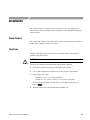

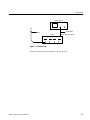

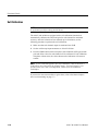


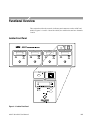


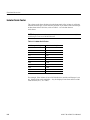
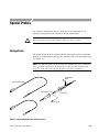

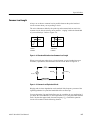

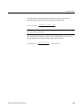


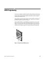


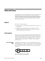

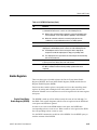
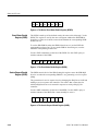

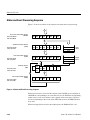


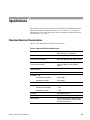
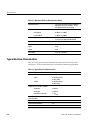


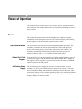


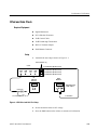

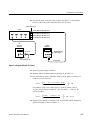
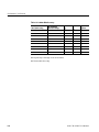


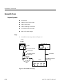


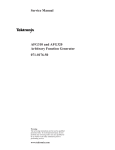


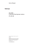
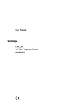

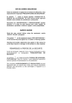


![[WAP035] [Evaluating Twittervane] Project Final Report](http://vs1.manualzilla.com/store/data/005882807_1-a2020170b6b6795bf72e9c3d683c54a5-150x150.png)