1
CP2000-ZX
USER MANUAL
020-100006-06
CP2000-ZX
USER MANUAL
020-100006-06
NOTICE
This equipment has been tested and found to comply with the limits for a Class A digital device, pursuant to Part 15 of
the FCC Rules. These limits are designed to provide reasonable protection against harmful interference when the
equipment is operated in a commercial environment. This equipment generates, uses, and can radiate radio frequency
energy and, if not installed and used in accordance with the instruction manual, may cause harmful interference to radio
communications. Operation of this equipment in a residential area is likely to cause harmful interference in which case
the user will be required to correct the interference at his own expense.
This Class A digital apparatus complies with Canadian ICES-003.
Cet appareil numérique de la classe A est conforme à la norme NMB-003 du Canada.
The equipment is designed and manufactured with high-quality materials and components that can be recycled and
reused. This symbol
means that electrical and electronic equipment, at their end-of-life, should be disposed of
separately from regular waste. Please dispose of this equipment appropriately and according to local regulations. In the
European Union, there are separate collection systems for used electrical and electronic products. Please help us to
conserve the environment we live in!
Copyright 2007 - 2009 Christie Digital Systems USA, Inc. All rights reserved. All brand names and products are
trademarks, registered trademarks or trade names of their respective holders. Canadian manufacturing facility is ISO
9001 and 14001 certified. Performance specifications are typical, but may vary depending on conditions beyond
Christie’s control such as maintenance of the product in proper working conditions. Performance specifications are
available at the time of printing. Every effort has been made to ensure accuracy, however in some cases changes in the
products or availability could occur which may not be reflected in this document. Christie reserves the right to make
changes without notice or obligation.
WARRANTY
For complete information about Christie’s limited warranty, please contact your Christie Dealer. In addition to the other
limitations that may be specified in Christie’s limited warranty, the warranty does not cover:
a. Damage occurring during shipment, in either direction.
b. Projector lamps (See Christie’s separate lamp program policy).
c. Damage caused by use of a projector lamp beyond the recommended lamp life, or use of a lamp supplied by a supplier other than Christie.
d. Problems caused by combination of the equipment with non-Christie equipment, such as distribution systems, cameras, video tape recorders, etc., or use of the equipment with any non-Christie interface device.
e. Damage caused by misuse, improper power source, accident, fire, flood, lightening, earthquake or other natural
disaster.
f. Damage caused by improper installation/alignment, or by equipment modification, if by other than Christie service
personnel.
g. For LCD projectors, the warranty period specified applies only where the LCD projector is in “normal use.” “Normal
use” means the LCD projector is not used more than 8 hours a day, 5 days a week. For any LCD projector where
“normal use” is exceeded, warranty coverage under this warranty terminates after 6000 hours of operation.
h. Failure due to normal wear and tear.
PREVENTATIVE MAINTENANCE
Preventative maintenance is an important part of the continued and proper operation of your projector. Please see the
Maintenance section for specific maintenance items as they relate to your projector and/or model. Failure to perform
maintenance as required and in accordance with the maintenance schedule specified by Christie will void the warranty.
Table of Contents
1 Introduction
1.1 Using this Manual........................................................................................................................1-2
1.2 Purchase Record and Service Contacts .......................................................................................1-3
1.3 Projector Overview......................................................................................................................1-4
1.3.1 Key Features ........................................................................................................................1-4
1.3.2 How the Projector Works ....................................................................................................1-5
1.3.3 User Interface Overview......................................................................................................1-5
1.3.4 List of Components..............................................................................................................1-5
1.3.5 Software Requirements........................................................................................................1-5
1.4 Labels and Marking .....................................................................................................................1-6
1.4.1 Typographical Notations......................................................................................................1-6
2 Installation & Setup
2.1 Projector Installation....................................................................................................................2-2
2.2 Connecting Sources .....................................................................................................................2-12
2.2.1 Connecting for Communications .........................................................................................2-13
2.3 Re-wiring For Uninterruptible Power Supply (UPS) ..................................................................2-14
2.4 Adjusting Tilt and Leveling.........................................................................................................2-15
2.4.1 Adjusting Tilt.......................................................................................................................2-15
2.4.2 Adjusting Feet/Leveling ......................................................................................................2-15
2.4.3 Carrying/Moving the Projector............................................................................................2-15
2.5 Initial Power Up...........................................................................................................................2-16
2.6 Maximizing Light Output ............................................................................................................2-16
2.6.1 Calibrating Screen Brightness (fL) ......................................................................................2-17
2.7 Basic Image Alignment ...............................................................................................................2-18
2.7.1 Basic Optical Alignment Procedure ....................................................................................2-18
2.8 Offset and Boresight Alignment ...........................................................................................................2-18
2.8.1 Adjust Offset........................................................................................................................2-19
2.8.2 Adjusting Left/Right Boresight ...........................................................................................2-19
2.8.3 Adjust Top/Bottom Boresight..............................................................................................2-21
2.8.4 Copy the Channel Settings To Another Channel.................................................................2-22
2.8.5 Add Anamorphic Lens.........................................................................................................2-22
2.8.6 Wide Converter Lens ...........................................................................................................2-22
2.9 Fold Mirror and Convergence Adjustments ................................................................................2-23
2.9.1 DMD Convergence ..............................................................................................................2-23
2.9.2 Fold Mirror Adjustment.......................................................................................................2-23
2.10 Calibrating the System...............................................................................................................2-23
2.10.1 Color Calibration ..............................................................................................................2-23
2.10.2 Electronic Screen Masking ...............................................................................................2-24
2.10.3 Projector Configuration Files (PCFs) ...............................................................................2-24
3 Operation
3.1 About Projector Components ......................................................................................................3-2
3.1.1 Air Filter ..............................................................................................................................3-2
3.1.2 Control Display Panel (CDP) ..............................................................................................3-2
CP2000-ZX User Manual
020-100006-06 Rev. 1 (12-2009)
i
Table of Contents
3.1.3 Douser ..................................................................................................................................3-2
3.1.4 Exhaust Duct ........................................................................................................................3-2
3.1.5 Adjustable Leveling Feet .....................................................................................................3-2
3.1.6 Lamps...................................................................................................................................3-3
3.1.7 Lens Mount and Motorized Auxiliary Lens Mount .............................................................3-3
3.1.8 Security Locks......................................................................................................................3-3
3.1.9 Source and Communication Panel .......................................................................................3-3
3.1.10 Auxiliary Panel .................................................................................................................3-4
3.2 Powering Up/Powering Down the Projector................................................................................3-4
3.2.1 Powering Up the Projector ...................................................................................................3-4
3.2.2 Powering Down the Projector ..............................................................................................3-5
3.2.3 Projector Power States .........................................................................................................3-5
Fast Boot Mode .....................................................................................................................3-5
Fast Cool Mode .....................................................................................................................3-5
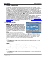
3.3 Using the Control Display Panel (CDP) ......................................................................................3-6
3.3.1 CDP Key Descriptions .........................................................................................................3-6
Guidelines for Using the CDP ..............................................................................................3-6
3.3.2 Navigating the CDP Menus .................................................................................................3-7
Icons ......................................................................................................................................3-7
Pull-Down Lists ....................................................................................................................3-7
Using Slide Bar Controls ......................................................................................................3-8
Editing Text or Numerical Values ........................................................................................3-8
Channel Menu .......................................................................................................................3-8
Lamp Menu ...........................................................................................................................3-9
Lens Control Menu ...............................................................................................................3-9
Configuration Menu ..............................................................................................................3-10
Status Menu and Alarm Conditions ......................................................................................3-11
Test Patterns Menu ...............................................................................................................3-11
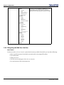
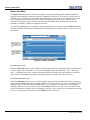
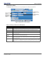
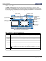
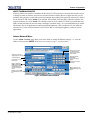
3.4 Using the Web User Interface......................................................................................................3-12
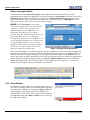
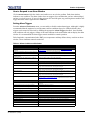
3.4.1 User Access and Rights........................................................................................................3-12
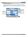
3.4.2 Navigating the Web User Interface......................................................................................3-14
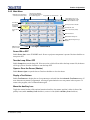
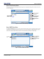
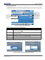
3.4.3 Main Menu ..........................................................................................................................3-15
Power ON or OFF .................................................................................................................3-15
Turn the Lamp ON or OFF ...................................................................................................3-15
Open or Close the Douser (Shutter) ......................................................................................3-15
Display a Test Pattern ...........................................................................................................3-15
Move the Auxiliary Lens ......................................................................................................3-15
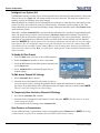
Intelligent Lens System (ILS) ...............................................................................................3-16
To Enable ILS Per Channel ..................................................................................................3-16
To Edit Active Channel ILS Settings ...................................................................................3-16
To Temporarily Alter the Active Channel ILS Settings .......................................................3-16
Start Features or Presentations ..............................................................................................3-16
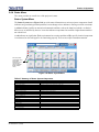
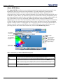
3.4.4 Status Menu..........................................................................................................................3-17
Status: System Menu ............................................................................................................3-17
Status: Test Menu .................................................................................................................3-20
Status: Status Summary Menu ..............................................................................................3-21
ii
CP2000-ZX User Manual
020-100006-06 Rev. 1 (12-2009)
Table of Contents
Status: SMPTE Errors Menu ................................................................................................3-21
Status: Interrogator Menu .....................................................................................................3-22
3.4.5 Alarm Window ....................................................................................................................3-22
How to Respond to an Alarm Window ................................................................................3-23
Setting Alarm Triggers .........................................................................................................3-23
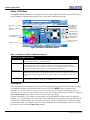
3.4.6 Channel Menu......................................................................................................................3-24
Channel: Page 1 and Page 2 Menus ......................................................................................3-24
Channel: Page 1 Menu ..........................................................................................................3-24
Channel: Page 2 Menu ..........................................................................................................3-26
Channel: 3D Control Menu ..................................................................................................3-27
Channel: Lamp Per Channel Menu ......................................................................................3-29
Channel: Lens Menu .............................................................................................................3-30
Channel: Lens Menu Disabled .............................................................................................3-31
3.4.7 Advanced Menu...................................................................................................................3-32
Advanced: Preferences Menu ...............................................................................................3-32
Advanced: Lamp Menu ........................................................................................................3-33
Advanced: Lamp History Menu ...........................................................................................3-34
Detailed Lamp Logging ........................................................................................................3-34
Advanced: Lens Menu ..........................................................................................................3-35
Advanced: Test Patterns Menu .............................................................................................3-36
Advanced: User Menu ..........................................................................................................3-37
3.4.8 Admin Menu ........................................................................................................................3-38
Admin: Source Menu ............................................................................................................3-38
Admin: Screen Menu ............................................................................................................3-40
Admin: MCGD Menu ...........................................................................................................3-42
Admin: TCGD Menu ............................................................................................................3-44
Admin: Network Menu .........................................................................................................3-45
Admin: General Menu ..........................................................................................................3-46
Admin: Lamp Menu .............................................................................................................3-47
3.4.9 About Menu .........................................................................................................................3-48
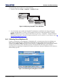
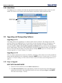
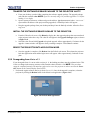
3.5 Upgrading and Downgrading Software .......................................................................................3-48
Upgrading to v2.x .................................................................................................................3-48
Upgrading to v3.0 .................................................................................................................3-48
3.5.1 Steps to Upgrade..................................................................................................................3-48
3.5.1 Boot into failsafe mode........................................................................................................3-48
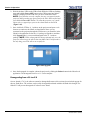
b. transfer the software upgrade package to the projector via ftp................................................3-49
c. install the software upgrade package to the projector..............................................................3-49
b. reboot the projector into application mode. ..............................................................................3-49
3.5.2 Downgrading from v2.x to v1.1...........................................................................................3-49
4. Downgrading from v3.0 to v2.x................................................................................................3-50
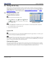
3.6 Working with the Lamp...............................................................................................................3-51
3.6.1 Turning the Lamp ON or OFF.............................................................................................3-51
Using the Web User Interface ..............................................................................................3-51
Using the CDP ......................................................................................................................3-51
If the Lamp Fails to Ignite ....................................................................................................3-51
CP2000-ZX User Manual
020-100006-06 Rev. 1 (12-2009)
iii
Table of Contents
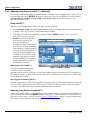
3.6.2 Adjusting Lamp Power (LiteLOC™ or Manually)..............................................................3-52
Using LiteLOC™ ..................................................................................................................3-52
Adjusting Lamp Position (LampLOC™) .............................................................................3-52
3.6.3 Age of a Lamp......................................................................................................................3-54
When to Replace a Lamp ......................................................................................................3-54
Lamp Rotation ......................................................................................................................3-54
Maintaining Footlamberts .....................................................................................................3-54
3.7 Working with the Lenses .............................................................................................................3-55
3.7.1 Lens Mount Functions .........................................................................................................3-55
Focus .....................................................................................................................................3-55
Offsets ...................................................................................................................................3-55
Zoom .....................................................................................................................................3-55
3.8 Working with 3D .........................................................................................................................3-56
3.8.1 Requirements for 3D ............................................................................................................3-56
3.8.2 Hardware Setup....................................................................................................................3-57
3.8.3 3D Instructions .....................................................................................................................3-57
Hardware Instructions ...........................................................................................................3-57
Web User Interface Instructions ...........................................................................................3-57
3.8.4 3D Troubleshooting .............................................................................................................3-59
3D Test Pattern .....................................................................................................................3-59
Image Breakup ......................................................................................................................3-59
No 3D Effect .........................................................................................................................3-59
Ghosting / Cross-talk ............................................................................................................3-59
Motion Artifacts ....................................................................................................................3-59
Single 3D Input Not Working ...............................................................................................3-59
3.9 Cinema Operation ........................................................................................................................3-60
3.9.1 Compatible Cinema Sources ................................................................................................3-60
3.9.2 Image Formats......................................................................................................................3-61
Projector Variables: Using an Anamorphic Lens .................................................................3-61
Projector Variables: Using a Wide Converter Lens ..............................................................3-62
Theatre Variables: Masking ..................................................................................................3-62
3.10 Non-Cinema Operation..............................................................................................................3-63
3.10.1 Selecting a Source .............................................................................................................3-63
4 Maintenance
4.1 Safety Warnings and Guidelines..................................................................................................4-2
4.1.1 Labels and Marking .............................................................................................................4-2
4.1.2 General Precautions .............................................................................................................4-2
4.1.3 AC / Power Precautions .......................................................................................................4-3
4.1.4 Lamp Precautions.................................................................................................................4-3
Wear Protective Clothing ......................................................................................................4-3
Cool the Lamp Completely ...................................................................................................4-3
4.2 Maintaining Proper Cooling ........................................................................................................4-4
4.2.1 Ventilation............................................................................................................................4-4
4.2.2 Air Filter...............................................................................................................................4-4
iv
CP2000-ZX User Manual
020-100006-06 Rev. 1 (12-2009)
Table of Contents
4.2.3 Liquid Cooler.......................................................................................................................4-4
Filling the Coolant Reservoir ...............................................................................................4-5
4.2.4 Exhaust Duct and Lamp Fan Interlocks...............................................................................4-5
4.3 Maintenance and Cleaning ..........................................................................................................4-6
4.3.1 Lamp ....................................................................................................................................4-6
4.3.2 Optical..................................................................................................................................4-6
4.3.3 Cleaning the Lens ................................................................................................................4-6
4.3.4 Cleaning the Reflector .........................................................................................................4-7
4.3.5 Other Components ...............................................................................................................4-7
Lamp Fan ..............................................................................................................................4-7
Igniter ....................................................................................................................................4-7
Airflow Interlocks .................................................................................................................4-8
Laminar Airflow Device (LAD) ...........................................................................................4-8
4.4 Replacing the Lamp.....................................................................................................................4-8
4.5 Replacing the Filter .....................................................................................................................4-11
4.6 Replacing the Lens ......................................................................................................................4-11
5 Troubleshooting
5.1 Power ...........................................................................................................................................5-2
5.1.1 Projector Will Not Start .......................................................................................................5-2
5.2 Lamp ............................................................................................................................................5-2
5.2.1 Lamp Does Not Ignite..........................................................................................................5-2
5.2.2 Lamp Suddenly Goes Off ....................................................................................................5-2
5.2.3 Flicker, Shadows Or Dimness .............................................................................................5-2
5.2.4 LampLOC™ Does Not Seem to Work................................................................................5-3
5.2.5 LiteLOC™ Does Not Seem to Work...................................................................................5-3
5.3 CDP .............................................................................................................................................5-4
5.3.1 Blank Screen, No Menu Displaying ....................................................................................5-4
5.3.2 Projector ON, but No Light at the CDP...............................................................................5-4
5.4 Ethernet........................................................................................................................................5-4
5.4.1 Trouble Establishing Communication with Projector .........................................................5-4
5.5 Cinema Displays..........................................................................................................................5-4
5.5.1 Blank Screen, No Display of Cinema Image.......................................................................5-4
5.5.2 Severe Motion Artifacts.......................................................................................................5-5
5.5.3 Image Appears Vertically Stretched or ‘Squeezed’ into Center of Screen..........................5-5
5.5.4 No Image, Just Pink Snow...................................................................................................5-5
5.6 Non-Cinema Displays..................................................................................................................5-5
5.6.1 The Projector is On but there is No Display........................................................................5-5
5.6.2 The Display is Jittery or Unstable........................................................................................5-5
5.6.3 The Display is Faint.............................................................................................................5-6
5.6.4 The Upper Portion of the Display is Waving, Tearing or Jittering......................................5-6
5.6.5 Portions of the Display are Cut Off or Warp to the Opposite Edge ....................................5-6
5.6.6 The Display appears Compressed (Vertically Stretched) ....................................................5-6
5.6.7 Data is Cropped from Edges................................................................................................5-6
5.6.8 Display Quality appears to Drift from Good to Bad, Bad to Good .....................................5-6
5.6.9 The Display has Suddenly Froze .........................................................................................5-6
CP2000-ZX User Manual
020-100006-06 Rev. 1 (12-2009)
v
Table of Contents
5.6.10
5.6.11
5.6.12
5.6.13
Colors in the Display are Inaccurate .................................................................................5-6
The Display is Not Rectangular ........................................................................................5-6
The Display is “Noisy” .....................................................................................................5-7
There are Random Streaks on the Bottom of the Image ...................................................5-7
6 Specifications
6.1 Display .........................................................................................................................................6-2
6.1.1 Panel Resolution and Refresh Rate ......................................................................................6-2
6.1.2 Achievable Brightness (Measured at Screen Center) ..........................................................6-2
6.1.3 Achievable Contrast Ratio ...................................................................................................6-2
6.1.4 Color and Gray Scale ...........................................................................................................6-2
6.1.5 White Point ..........................................................................................................................6-2
6.1.6 Gamma .................................................................................................................................6-2
6.2 Inputs ...........................................................................................................................................6-2
6.2.1 Cinema Inputs ......................................................................................................................6-2
6.2.2 Non-Cinema DVI Inputs (for Alternate Content) ................................................................6-3
6.2.3 Control Ports ........................................................................................................................6-3
6.3 Control Display Panel (CDP) ......................................................................................................6-3
6.4 Power Requirements ....................................................................................................................6-4
6.4.1 Projection Compartment AC................................................................................................6-4
6.4.2 Lamp Ballast AC Input ........................................................................................................6-4
6.4.3 DC Input for Lamp...............................................................................................................6-4
6.4.4 UPS Input .............................................................................................................................6-4
6.5 Lamps...........................................................................................................................................6-5
6.6 Physical Specifications ................................................................................................................6-5
6.7 Regulatory....................................................................................................................................6-5
6.8 Environment.................................................................................................................................6-6
6.9 Optional Components ..................................................................................................................6-6
6.10 Lamp Components .....................................................................................................................6-7
6.11 Standard Components ................................................................................................................6-7
Appendix A: Serial API
Appendix B: SCCI Port
Appendix C: GPIO
C.1 The GPIO Port.............................................................................................................................C-2
Appendix D: CDP Error Codes
vi
CP2000-ZX User Manual
020-100006-06 Rev. 1 (12-2009)
1
Introduction
This section includes information on the following:
• 1.1 Using this Manual
• 1.2 Purchase Record and Service Contacts
• 1.3 Projector Overview
CP2000-ZX User Manual
020-100006-06 Rev. 1 (12-2009)
1-1
Section 1: Introduction
1.1
Using this Manual
USERS/OPERATORS: This manual is intended for trained users authorized to operate professional highbrightness projection systems located in restricted areas such as projection rooms in theatres. Such users may
also be trained to replace the lamp and air filter, but cannot install the projector or perform any other functions
inside the projector.
SERVICE: Only trained and qualified Christie service technicians knowledgeable about all potential hazards
associated with high voltage, ultraviolet exposure and high temperatures generated by the lamp and associated
circuits are authorized to 1) assemble/install the projector and 2) perform service functions inside the projector.
This manual contains the following sections:
• Section 1 Introduction
• Section 2 Installation & Setup
• Section 3 Operation
• Section 4 Maintenance
• Section 5 Troubleshooting
• Section 6 Specifications
• Appendix A: Serial API
• Appendix B: SCCI Port
• Appendix C: GPIO
• Appendix D: CDP Error Codes
Disclaimer: Every effort has been made to ensure the information in this document is accurate and reliable. However, due to ongoing
research, the information in this document is subject to change without notice. Christie Digital Systems assumes no responsibility for
omissions or inaccuracies. Updates to this document are published regularly, as required. Please contact Christie Digital Systems for
availability.
1-2
CP2000-ZX User Manual
020-100006-06 Rev. 1 (12-2009)
Section 1: Introduction
1.2
Purchase Record and Service Contacts
Whether the projector is under warranty or the warranty has expired,
Christie’s highly trained and extensive factory and dealer service
network is always available to quickly diagnose and correct projector
malfunctions. Complete service manuals and updates are available for
all projectors. Should you encounter a problem with any part of the
projector and require assistance, contact your dealer. In most cases,
servicing is performed on site. If you have purchased the projector, fill
out the information below and keep it with your records.
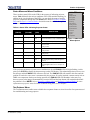
Table 1.1 Purchase Record
Dealer:
Dealer Phone Number:
Projector Serial Number*:
Purchase Date:
Installation Date:
* The serial number can be found on the license label located on the front of the projector.
Table 1.2 Ethernet Settings
The following ethernet settings were defined during the installation of this projector.
Default Gateway
DNS Server
Projector Address
Projector Mgmt IP Address
Subnet Mask
CP2000-ZX User Manual
020-100006-06 Rev. 1 (12-2009)
1-3
Section 1: Introduction
1.3
Projector Overview
The CP2000-ZX is a professional quality, easy-to-use Digital Micromirror Device (DMD) projector utilizing
Digital Light Processing (DLP™) Cinema technology from Texas Instruments. It’s all-in-one design integrates
all components in a sleek projection head that can be table-top mounted or used with the optional rack stand.
Integrating smoothly into traditional projection environments such as theatres and other wide screen exhibitor
venues, the CP2000-ZX offers stunning wide screen, high-resolution cinema images that remain flawless from
first release to final show.
CP2000-ZX interfaces with local networks typical in theatres throughout the world, and can be expanded even
further by connecting non-cinema DVI source material for multimedia presentations from a variety of formats.
1.3.1 Key Features
• 2048 x 1080 native pixel format (DC2K)
• CineBlack™ and CinePalette™ for deep film-like blacks and superior colorimetry
• CineCanvas™ for flexible telecine-grade resizing, subtitling and other text and graphic overlays
• Two SMPTE 292M cinema inputs, used individually or simultaneously for high-speed, dual-link processing
and each supporting CineLink™II local-link encryption
• Dual DVI (Digital Visual Interface) connectors for alternative “non-cinema” content, used individually or as a
single-twin or dual-link input for high-speed processing
• LiteLOC™ feature for constant image brightness
• LampLOC™ for motorized three-axis lamp alignment (automatic or custom-bulb positioning)
• Electronically operated “quick” douser
• Choice of field-interchangeable zoom lenses and one optional anamorphic lens
• Optional lens mount for 1.25x anamorphic lens producing 2.39:1 “scope” image format
• Communication ports for remote control of the projector via PC or other controller
• Local user interface via Control Display Panel (CDP)
• Custom web user interface for controlling projector remotely, as well as remote diagnostics
• Service access panels lockable with medium-security locks
• Content protected by high-security locks on electronics compartment
• One 10/100BaseT Ethernet port for connection to in-theatre Ethernet hub
• Service port for additional flexibility
• Two RS-232 ports for communication with Christie-supported peripherals (except Cine-IPM 2K)
• One GPIO port for connection of automation
• One Simple Contact Closure Input (SCCI) for automated Lamp Start and Dowser operation
• HDCP decryption on both DVI inputs for display of copy protected alternate content.
• One USB port for direct laptop connection, useful during setup and local software downloads
• Health Status Output for operation status
• Triple Flash functionality, capable of projecting full resolution 3D images under a 6:2 frame rate multiplication.
• Motorized Lens Mount automates the process of setting the Focus, Horizontal (X) and Vertical (Y) Offset, and
Zoom. NOTE: PCM version 2.2 or higher is required.
1-4
CP2000-ZX User Manual
020-100006-06 Rev. 1 (12-2009)
Section 1: Introduction
1.3.2 How the Projector Works
The CP2000-ZX accepts a variety of cinema or DVI-compatible “non-cinema” signals for projection on front
screens typical in commercial theatre or other large screen applications. High-brightness light is generated by a
short arc Xenon lamp, then modulated by three Digital Micromirror Device (DMD) panels responding to
incoming data streams of digitized red, green and blue color information. As these digital streams flow from
the source, light from the responding “on” pixels of each panel is reflected, converged and then projected to the
screen through one or more front lenses, where all pixel reflections are superimposed in sharp full-color
images.
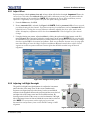
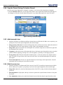
1.3.3 User Interface Overview
The CP2000-ZX incorporates two basic user interface systems: the Control Display Panel and the Web User
Interface.
The Control Display Panel (CDP) is a simple keypad with a small alphanumeric LCD display panel that can be
backlit for easy viewing in dark projection rooms. It is used for a simple setup, local control of power, lamp
douser control, channel selection, lamp installation and alignment, etc.
The Web User Interface is a Web-based interface produced internally by the projector, but displayed and
controlled by a Web-based browser on a remote, local area Ethernet network or at a distance over internet
protocol. The Web User Interface is a full function setup and diagnostic tool that can be set up via a wireless
Ethernet connection for easy data entry and calibration from the theatre auditorium where the color
measurements are taken.
1.3.4 List of Components
Make sure you have received the following components with your projector:
Projector with Control Display Panel (CDP)
Lens plug (required for shipping when lens is not installed to prevent contamination of critical optical components)
Nylon safety strap with clip (required to secure projector to tabletop or optional rack mount)
Warranty Card
Web Registration Form
1.3.5 Software Requirements
DLP version 14 series or higher
Projector Control Module (PCM) version 3.0 or higher
CP2000-ZX User Manual
020-100006-06 Rev. 1 (12-2009)
1-5
Section 1: Introduction
1.4
Labels and Marking
Observe and follow any warnings and instructions marked on the projector.
Danger symbols indicate a hazardous situation which, if not avoided, will result in death
or serious injury. This signal word is to be limited to the most extreme situations.
Warning symbols indicate a hazardous situation which, if not avoided, could result in
death or serious injury.
Caution symbols indicate a hazardous situation which, if not avoided, could result in
minor or moderate injury.
NOTICE! Addresses practices not related to personal injury.
1.4.1 Typographical Notations
The following notations are used throughout this manual:
• Keypad commands and PC keystrokes appear in bold small caps, such as POWER, INPUT, ENTER etc.
• References to specific areas of the document appear italicized and underlined. When viewed online the text
appears in blue indicating a direct link to that section. For example,
Section 6 Specifications.
• References to other documents appear italicized and bold, such as Christie Service Manual.
• References to software menus and available options appear bold, such as Main Menu, Preferences.
• User input or messages that appear on screen, in status display units or other control modules appear in
Courier font. For example. “No Signal Present”, Login: christiedigital.
• Error codes, LED status appear in bold, e.g. LP, A1 etc.
• Operational states of modules appear capitalized, such as “power ON, power OFF”.
• Signal words, such as Warning, Caution and Notes are used in this manual to point the reader to specific
information or instructions that warn of safety related hazards which may be present and indicates how to
avoid them.
1-6
CP2000-ZX User Manual
020-100006-06 Rev. 1 (12-2009)
2
Installation & Setup
This section explains how to install, connect and optimize the projector for delivery of superior
image quality. NOTE: The illustrations throughout this manual are provided to enhance the
understanding of written material. They are graphical representations only and may not
represent your exact projector model.
• 2.1 Projector Installation
• 2.2 Connecting Sources
• 2.3 Re-wiring For Uninterruptible Power Supply (UPS)
• 2.4 Adjusting Tilt and Leveling
• 2.5 Initial Power Up
• 2.6 Maximizing Light Output
• 2.7 Basic Image Alignment
• 2.8 Offset and Boresight Alignment
• 2.9 Fold Mirror and Convergence Adjustments
• 2.10 Calibrating the System
CP2000-ZX User Manual
020-100006-06 Rev. 1 (12-2009)
2-1
Section 2: Installation & Setup
2.1
Projector Installation
The following set of instructions explains how to install, connect and optimize the projector for smooth
operation.
QUALIFIED TECHNICIAN REQUIRED for all installations. This product must
be installed in a restricted access location.
Auto LampLOC™ must be run any time the projector is physically moved or
when it has been leveled.
Before you begin installation, it is important to fully understand all site requirements and characteristics, and
that you have the following tools and components on hand. NOTE: In general, fasteners are metric sizes and
require metric tools. However, to complete lamp installation, imperial tools are required, which have been
provided inside the lamp door of the projector.
12” screwdrivers: Phillips #2 (magnetic) and flat
19 mm and 7/8” wrenches
Assorted Allen keys (metric)
Single-phase 30A connection of AC supply to the terminal block
Installation site must have an easily accessible 30-32A breaker nearby
Heat extractor (Refer to STEP 5 - Connect Exhaust Ducting, on page 2-5 for requirements)
Protective clothing / safety gear (required when handling the lamp)
Lens cleaning tissue and solution
STEP 1 - Carrying/Moving the Projector
Four or more people are required to safely lift and hand-carry one projection
head a short distance.
Keep the projector as level as possible when lifting or carrying the projector.
Avoid tilting the projector on the right side. This can introduce an air bubble within the coolant hoses that can lead to an air lock.
STEP 2 - (Optional) Install Projector on Rack Stand
Use of the projector’s safety strap is MANDATORY to prevent the projector
from tipping. Secure the strap between the projector and the optional rack-mount or any
other surface it is mounted to.
An optional rack stand (P/N 108-272101-01 or P/N 108-282101-01) and hold down clamp (P/N 116-10010101) are available for use with the projector. If you intend to use this in your installation, refer to the instructions
provided with the rack stand before proceeding with STEP 3.
2-2
CP2000-ZX User Manual
020-100006-06 Rev. 1 (12-2009)
Section 2: Installation & Setup
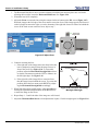
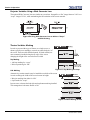
STEP 3 - Position the Projector
1) It requires four or more people to safely lift and hand-carry one projection
head a short distance as required. 2) Use of the projector’s safety strap is MANDATORY to
prevent the projector from tipping. Secure the strap between the projector and the optional
rack-mount or any other surface it is mounted to.
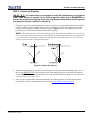
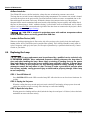
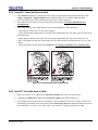
1. Position the projector at an appropriate throw distance (projector-to-screen distance) and vertical position.
Ideally, center the projector with the theatre screen. If competing for space with an already present film
projector, aim the projector slightly off-center as shown in Figure 2-1. This will slightly increase side
keystoning, but will minimize the horizontal lens offset required.
NOTE: Unlike film projectors, it is best to keep the projector lens surface as parallel to the screen as possible, even if significantly above the screen center. When a particularly short throw distance combines with
a very wide screen, you may have to forfeit some aim and stay more parallel to the screen. In such cases,
some lens offset can reduce the keystone distortion.
Figure 2-1 Position the Projector
2. Attach the supplied safety strap to the back of the projector and fasten it to the mounting surface. Use of
this strap is MANDATORY to prevent the projector from tipping when a lens or auxiliary lens mount is
installed. NOTE: It is also recommended that you use the optional hold down clamp (P/N 116-100101-01)
be used to firmly secure the rear feet.
3. Once you have completed the remaining installation steps and the projector is up-and-running, adjust
precise image geometry and placement as described in Section 2.7 Basic Image Alignment.
CP2000-ZX User Manual
020-100006-06 Rev. 1 (12-2009)
2-3
Section 2: Installation & Setup
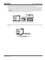
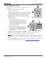
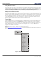
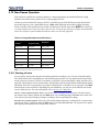
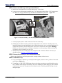
STEP 4 - (Optional) Mount the Control Display Panel
The projector is shipped with the Control Display Panel (CDP) fully assembled
and installed to the back panel. For convenience, the display angle of the CDP
can easily be modified for improved viewing or it can be removed and
permanently mounted in another location within the projection room. NOTE:
The CDP is not recommended for use as a handheld remote.
To modify the CDP display angle:
1. Place your hand under the bottom edge of the CDP and pull forward to the
desired angle. Keep the back tab of the CDP fully engaged in the projector.
See Figure 2-2.
Figure 2-2 Change
Display Angle of CDP
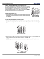
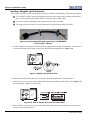
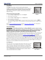
To remove the CDP for installation in another location:
1. Grasp the CDP and slightly push it to one side. This creates a gap sufficient enough to release the CDP
from the top mounting pin on that side. Then release the other side and pull forward to remove. See Figure
2-3.
Figure 2-3 Remove CDP
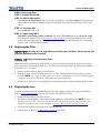
2. When installing the CDP in a new location, be sure to keep the distance between the projector and the CDP
within 6 ft (the max. length of the standard CDP harness). See Figure 2-4.
NOTE: An optional 25ft CDP harness kit is available if more length is required (P/N 108-283101-01).
Figure 2-4 CDP Mounting
2-4
CP2000-ZX User Manual
020-100006-06 Rev. 1 (12-2009)
Section 2: Installation & Setup
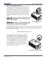
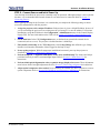
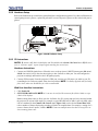
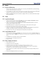
STEP 5 - Connect Exhaust Ducting
The projector emits a constant stream of warm exhaust air, which must
be vented to the outside of the building. Connect the pre-installed,
outside-venting ductwork via the 8” inside diameter fireproof ducting
material attached to the projector’s top exit port. Confirm that 1) there
are no obstructions or ‘kinks” within the ducting, 2) all air intake areas
of the projector are clear and exposed, 3) the vane switch at the exit duct
is moving freely. The pre-installed outside-venting duct should be rigid
at the projector and must also include a heat extractor/blower that
maintains at least 450 CFM* when measured at the projector exhaust
opening.
* 600 CFM is required in projection rooms with
ambient temperature above 25°C or elevation (above sea
level) greater than 3000 feet.
At minimum, a 10” long, strong metal duct
must be in place at the projector to prevent glass shards
from exiting the duct in the event of a lamp explosion.
Figure 2-5 Connect Exhaust
Ducting
Calculating CFM in the 8” duct: Use an airflow meter to measure the ft/min or ft/sec at the rigid end of the
open duct that will connect to the projector. Make sure the measurement is taken right at the very end, without
the projector connected. Then multiply the reading by the cross-sectional area of the 8” duct to calculate the
cubic feet/min airflow. The formula is:
Measured linear ft/min x 0.34 = CFM
Calculations should show 450 CFM airflow in the 8” exhaust
duct if operation is at 25°C or lower and installation is at or below
3000 feet altitude (above sea level). Add an extractor/boosters as
needed for your site, as the vane switch will prevent the projector
from operating if there is insufficient airflow. Do not mount the
extractor on the projector as this may introduce some vibration
into the image. NOTE: If the duct becomes significantly blocked
- or if a fan fails - the projector should trigger an alarm before
becoming overheated or unsafe. Regardless, check airflow
regularly. Caution! Never disable the vane switch. Attempting to
operate the projector with inadequate airflow can result in
dangerous overheating of the projector.
Figure 2-6 Exhaust Duct Vane Switch
CP2000-ZX User Manual
020-100006-06 Rev. 1 (12-2009)
2-5
Section 2: Installation & Setup
STEP 6 - Install Lens(es)
The lens seals the projector preventing contaminants from entering the area of the main front electronics. It is
important a projector never be operated without a lens installed. The Motorized Lens Mount automates the
adjustment of focus, horizontal/vertical offset and zoom for the primary lens.
For Primary Zoom Lens Installation:
1. Ensure the projector’s rear safety strap is in place.
2. Turn the lens clamp to the OPEN position. See Figure 2-7.
Figure 2-7 Open Lens Clamp and
Insert Lens
3. Orient your high-contrast lens with its notches at the top. Fully insert the assembly straight into the lens
mount opening without turning. When the lens is fully inserted, it will seat properly within the lens mount
and the aperture will be oriented correctly. NOTE: Insert a high-brightness lens in the same manner, with
the UP label in the up position for consistency.
4. Position the lens clamp DOWN to lock the lens assembly in place.
See Figure 2-8.
5. Use of the optional lens safety strap is required if the projector is
mounted in a high location where the lens could drop (if it
becomes loose by vibrating) and cause physical injury. NOTE:
Use of this strap is optional if the projector is table-top mounted,
but strongly recommended.
6. Calibrate the lens. See Section 2.7 Basic Image Alignment for
details.
For Auxiliary Lens Installation (Optional):
To install a 1.26x Anamorphic lens or a 1.26x Wide Converter Lens
Figure 2-8 Lock Lens In Place
(WCL) producing 2.39:1 “scope” images for large screens, install the
auxiliary lens mount and lens to the projector using the hardware and instructions provided in the Auxiliary
Lens Mount Kit (P/N 108-111101-02, P/N 108-111102-xx).
2-6
CP2000-ZX User Manual
020-100006-06 Rev. 1 (12-2009)
Section 2: Installation & Setup
STEP 7 - Install First Lamp
Qualified technicians required! High-pressure lamp may explode if improperly
handled. Always wear approved protective safety clothing whenever lamp door is open or
while handling the lamp.
1. Open lamp door
Using the security key provided, open the lamp door and inspect the empty lamp cooling compartment.
Caution! Do not place heavy objects on the open lamp door.
2. Position anode yoke assembly according to lamp type
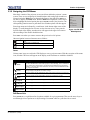
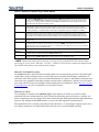
Check the position of the anode yoke assembly for the lamp type that will be used in the projector. Table
2.1 lists all available lamp types for the CP2000-ZX and the position of the anode yoke assembly.
Table 2.1 Lamp Types Available for CP2000-ZX and Anode Yoke Position
LAMP
TYPE
ANODE YOKE POSITION
2.0 kW
CDXL-20
Move the lamp cradle as far forward as possible (position closest to igniter)
3.0 kW
CDXL-30
3.0 kW
CDXL-30SD (short arc)
Move the lamp cradle to the rear position, which is approximately 1” closer to
the reflector.
3. Install the lamp. Refer to Section 4.4 Replacing the Lamp for lamp replacement instructions. Observe all
warnings, and wear protective clothing and shielding.
Important! The projector is shipped with a lamp extension nut fastened to the cathode end of the lamp
holder. Use this nut with CDXL-30SD lamps only. This will ensure proper placement of this lamp type. If you
are installing any other lamp type, remove this nut and retain it for future lamp replacements. Leaving the
extension nut on with the wrong lamp type can lead to extremely dim light output.
Figure 2-9 Anode Yoke Location
CP2000-ZX User Manual
020-100006-06 Rev. 1 (12-2009)
2-7
Section 2: Installation & Setup
STEP 8 - Connect to Power
CP2000-ZX is designed as a permanently wired connection or pluggable type B connection (P/N 116-10210401). Connecting the projector to your AC supply can vary according to the country or state in which the
projector is installed. For any installation, always follow the electrical code for your location.
1) Certified electrician required. 2) Ground (earth) connection is necessary
for safety. Never compromise safety by returning the current through the ground. 3) Connect
ground FIRST to reduce shock hazard from high leakage. 4) Protection from overcurrents,
short circuits and earth faults must be part of the building installation. The disconnect device
(double pole switch or circuit breaker with minimum 3mm contact gap) must be readily accessible within the projection room. 5) Do not use a wall breaker greater than 32SA.
Use an appropriate strain relief connector on the AC supply cable to prevent
the cable from rubbing against the projector knockout plate and becoming damaged.
To install a permanent connection, refer to Installing a Permanent Connection below.
To install a Pluggable type B connection using a Nema-L630A 250V Power Plug, refer to Installing a
Pluggable Type B Connection.below.
Installing a Permanent Connection
Follow these guidelines:
A 30-32A double pole, UL listed wall circuit breaker is required. It must be part of the building
installation and easily accessible.
Use 10AWG or 8AWG wiring: The distance between the wall circuit breaker and the projector must
not exceed 20 metres using 10AWG cables or 30 metres using 8AWG cables.
For North American installations, use at least 10AWG copper wires for the connection of the main
AC supply to the projector’s ground lug.
Copper or aluminum are acceptable as conductor wiring material to the terminal block.
1. A small electrical access plate is located in the lower right corner of the projector faceplate. Loosen the two
screws and slide the plate forward to expose the terminal block underneath. See Figure 2-10.
Figure 2-10 Remove Access and Knockout Plates
2-8
CP2000-ZX User Manual
020-100006-06 Rev. 1 (12-2009)
Section 2: Installation & Setup
2. Remove the knockout plate located in the bottom right corner of the front bezel. The AC supply is routed
to the terminal block through an appropriate strain relief mounted on this knockout plate.
3. Connect the AC power source to the terminal block, beginning with the ground lead first. See Figure 2-11
for wiring details. Use an appropriately sized strain relief connector with the knockout plate provided to
ensure adequate environmental sealing and to prevent the cables from wear and accidentally being torn
out. NOTES: 1) The terminal block accommodates up to an 8 AWG wire. 2) If desired, a 90° strain relief
connector can be used to route the power cable in a downward direction.
Figure 2-11 Steps to Connect AC Power to Terminal Block
4. Once all cables are connected, replace the knockout plate and the bottom access panel over the terminal
block.
Figure 2-12 Re-attach Knockout and
Access Panel Plates
CP2000-ZX User Manual
020-100006-06 Rev. 1 (12-2009)
2-9
Section 2: Installation & Setup
Installing a Pluggable Type B Connection
There must be easy access to the current protection device or breaker in the building. Follow these guidelines:
Use 10AWG or 8AWG wiring: the distance between the wall circuit breaker and the projector must
not exceed 20 metres using 10AWG cables or 30 metres using 8AWG cables.
The socket-outlet is installed near the equipment and is easily accessible.
The plug can be used as the device disconnect and is near the unit and easily accessible.
Figure 2-13 Nema-L630A 250V Male Power Plug (116-102104-01)
Actual Length 1.5 Meters
1. A small electrical access plate is located in the lower right corner of the projector faceplate. Loosen the two
screws and slide the plate forward to expose the terminal block underneath. See Figure 2-14.
Figure 2-14 Remove the Knockout Plate
2. Remove the knockout plate (four screws) located in the bottom right corner of the front bezel.
Green
Black
White
3. Connect the AC power source to the terminal block, beginning with the ground lead first. See Figure 2-15
for wiring details. Tighten screws securely.
Figure 2-15 Steps to Connect AC Power to Terminal Block
4. Once all cables are connected, secure the knockout plate (four screws) and the bottom access panel (two
screws) over the terminal block.
2-10
CP2000-ZX User Manual
020-100006-06 Rev. 1 (12-2009)
Section 2: Installation & Setup
STEP 9 - Connect Sources and Initial Power Up
Once the lamp is installed, the projector is essentially ready for operation. Although an image is not required at
this time, it is recommended that external cinema servers and sources be connected. Refer to Section 2.2
Connecting Sources.
Before igniting the lamp for the first time, it is essential that you complete the following settings to ensure
successful communication with the projector:
1. Assign the projector with a unique IP address. Each projector is given a default IP address, however if
you are connecting the projector to an existing network you must give it a new IP address. For first time
installations, assign the IP address in the Configuration > Administrator menu via the Control Display
Panel (CDP). For more information on the CDP, refer to Section 3.3 Using the Control Display Panel
(CDP).
2. Set the baud rate. In the CDP Configuration menu, set the baud rate to match the external device
connected (such as a server). The projector’s default baud rate is 9600 Kbps.
3. Enter details of the lamp. In the CDP Lamp menu, select Lamp Change and define the type of lamp
installed, serial number and number of hours logged on the lamp (if any).
4. Power-up the projector. With all components installed and connected, power-up the projector as
described in Section 3.2.1 Powering Up the Projector.
5. Perform LampLOC™ alignment immediately on the newly installed lamp. This ensures the lamp is
positioned correctly to achieve maximum light output. Refer to Section 2.5 Initial Power Up for
instructions.
6. Perform initial optical alignment in order to optimize images displayed on screen. These adjustments
must be done before boresight adjustments. Refer to Section 2.7 Basic Image Alignment for instructions.
7. Adjust optical components when needed. In rare instances, the installer may have to adjust one or more
optical components. Refer to Section 2.9 Fold Mirror and Convergence Adjustments for instructions.
CP2000-ZX User Manual
020-100006-06 Rev. 1 (12-2009)
2-11
Section 2: Installation & Setup
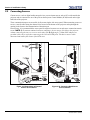
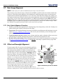
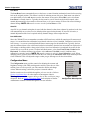
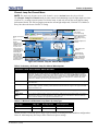
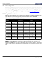
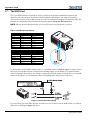
2.2
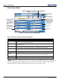
Connecting Sources
Cinema servers, such as digital media storage devices or non-cinema sources such as PCs reside outside the
projector and are connected to one of the ports on the Projector Control Module (PCM) located on the right
hand side of the projector.
These communication ports are accessible by first removing the side access panel. When connecting sources or
servers, route all cables along the channel ways located on the bottom of the projector and up through the
opening in the frame to the communication connection port.
Management
Ethernet
PWR
RS232 B
Management RS232 B
Ethernet
Service
Service
DVI-D A
DVI-D A
DVI-D B
DVI-D B
292 A 292 B
292 A 292 B
In most cases, it is recommended the access panel be replaced to ensure server and source connections remain
secure. NOTE: 1) To maintain radiated emissions compliance, do not connect I/0 cables to the projector
without connecting the source or receiver at the other end. 2) Right angle (75 Ohm) BNC adapters are
provided which can be used when connecting to the 292A and 292B ports. This directs source cables
downward and enables full closure of the PCM cover.
CPU
PWR
Connect to
AC at site
CPU
Connect to
AC at site
(optional)
Figure 2-16 Connecting an External
Cinema Server/Source
2-12
Figure 2-16 Connecting Non-Cinema
Servers/Sources
CP2000-ZX User Manual
020-100006-06 Rev. 1 (12-2009)
Section 2: Installation & Setup
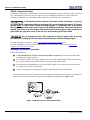
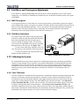
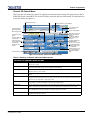
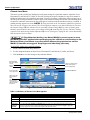
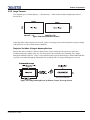
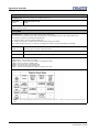
2.2.1 Connecting for Communications
Management
Ethernet
RS232 B
Service
DVI-D A
DVI-D B
292 A 292 B
Many communications with the projector are initiated on the CDP controller, which is mounted at the rear of
the projector. Depending on the installation, you may also need certain other serial and/or Ethernet links to the
CP2000-ZX, such as from a server or PC functioning as a controller, or from an existing on-site network
including other equipment. For applications or equipment utilizing serial communications, use the Christieproprietary serial protocol to connect to the RS232 B port on the PCM (Figure 2-17). Caution! The RS232 B
port located on the PCM utilizes Christie-proprietary protocol and is intended for Christie accessories or
automation controllers only. Do not connect other devices here.
PWR
CPU
Figure 2-17 Communication Links with Projector
Control Display Panel (CDP)
The CDP comes pre-installed and does not require further connection.
PC/Laptop, Server or Network
To communicate with the projector from a computer, server or an existing network, connect the equipment to
the Ethernet hub or switch at your site.
CP2000-ZX User Manual
020-100006-06 Rev. 1 (12-2009)
2-13
Section 2: Installation & Setup
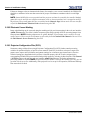
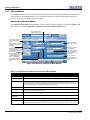
2.3
Re-wiring For Uninterruptible Power Supply (UPS)
Ensure power is disconnected before moving side panel.
If the unit is to be configured for UPS backup of the Low Voltage Power Supply (LVPS) (and subsequently the
electronics), rewiring is required.
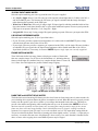
1. Remove the plastic cover over the AC relay by pinching the top and bottom of the cover and removing it.
2. Using a #2 Phillips screwdriver, loosen terminal screws 4 & 8 on the AC Relay and remove the Blue and
Brown wires coming from the LVPS. Leave the Black and White wires that lead into the base of the unit
(main input wiring) attached.
3. Remove the UPS terminal block cover and loosen the LVPS L and N screws.
4. Take the Blue and Brown wires out of the L and N clips and re-route these wires to the UPS terminal block
through the clip closest to it. Attach the Blue and Brown wires to the UPS terminal.
5. Take the Brown and Blue wires that were previously attached to the AC Relay and attach them to the LVPS
terminal. Attach the Brown wire to the L terminal and the Blue wire to the N terminal as shown in Figure
2-18. Torque screws to 14 in/lbs. Use clips to secure wires. Reattach cover.
6. Remove the previously loosened screws of the AC Relay (terminals 4 & 8). Attach the unattached LED
wires coming from the Ballast Power to the AC Relay terminals followed by Main Input wires. NOTE:
Order and orientation are important.
• Wire one LED terminal to the screw for terminal 4, followed by the White wire. Turn the terminals
so that they are back-to-back with the White wire facing down and the L2 facing up.
• Follow the same procedure for attaching the second LED lead and Black wire to terminal 8 of the
relay.
7. Tighten to 14 in/lbs and reattach the plastic cover to the AC Relay.
Step 1
Step 2
Remove AC Relay Cover
Step 9
Loosen terminal screws
4 and 8 and remove
LVPS Blue and Brown
wires.
Plug UPS into Outlet
2
4
6
8
Steps 6 - 7
Steps 3 - 5
Remove screws 4 and 8 from AC
Relay.
Connect LED to terminals followed
by Main Input wires. Note Order
and orientation are important:
Black facing down, L1 of LED Up
then screw into terminal 8.
White facing down, L2 of LED Up
then screw into terminal 4.
Tighten to 14 in-lbs.
Reattach cover.
Remove UPS terminal
block cover
Loosen LVPS L and N
screws.
Attach LVPS wires:
Brown to L
Blue to N
Tighten screws to
14 in-lbs
LVPS
L
N
Figure 2-18 Re-wiring for UPS
2-14
CP2000-ZX User Manual
020-100006-06 Rev. 1 (12-2009)
Section 2: Installation & Setup
8. Ensure the ground connection from the UPS input to the ground stud is secure.
9. Re-attach the side panel and plug an appropriate UPS that meets the required input specifications (refer to
Section 6.4.4 UPS Input) into the IEC connector on the auxiliary panel.
10. Re-connect main power, turn on the UPS power and ensure that the projector operates normally.
2.4
Adjusting Tilt and Leveling
Use of the supplied safety strap is MANDATORY to prevent the projector
from tipping forward while being adjusted for tilt or when the optical auxiliary lens is
installed.
Disconnect the projector from the AC for these initial alignments. Images are
not yet needed.
For an ideal installation, the CP2000-ZX lens surface should be centered and parallel to the theatre screen. This
orientation helps to ensure optimized lens performance with minimal offset. Choose a sturdy mounting surface
that allows for this. If this position is not possible (such as when the projector is significantly higher than the
center of the screen), it is better to rely on offset rather than extra tilt.
2.4.1 Adjusting Tilt
Important! For best optical performance, avoid tilting the projector excessively. Use vertical offset of the
lens instead.
Check with theatre personnel for the degree of screen tilt or measure this incline with a protractor at the screen.
Tilt the projector to match the screen tilt angle by extending or retracting the projector’s four adjustable feet.
NOTE: The front-to-back tilt of the projector must not exceed 15°. This limit ensures safe lamp operation and
proper position of the liquid cooling reservoir in the projector.
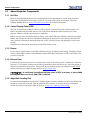
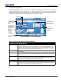
2.4.2 Adjusting Feet/Leveling
To adjust the height or level of the projector, extend or retract the adjustable
feet located on the bottom of the projector by rotating them. Once the
required adjustment is made, tighten the lock nut. See Figure 2-19. NOTE:
Make sure the projector’s rear safety strap is in place before adjusting.
2.4.3 Carrying/Moving the Projector
Four or more people are required to safely lift
and hand-carry one projection head a short distance. It is
strongly recommended the projector be kept as level as possible when carrying up stairs or lifting it onto a table.
Figure 2-19 Adjust Feet
Keep the projector as level as possible when lifting or carrying the projector. Avoid tilting the projector on the
right side. This can introduce an air bubble within the coolant hoses that can lead to an air
lock.
CP2000-ZX User Manual
020-100006-06 Rev. 1 (12-2009)
2-15
Section 2: Installation & Setup
2.5
Initial Power Up
This is a manual power-up procedure. Some cinema installations may include an automation system that controls lamp ignition in conjunction with other theatre variables such as house lights, audio and the start of the
feature from a digital media storage device/server. Warning! Do not attempt operation if the AC supply is not
within the specified voltage range.
1. Ensure the projector’s wall circuit breaker is ON. The “Ready” status LED will illuminate in solid yellow.
2. On the CDP, press POWER ON to fully power up the projector in preparation for igniting the lamp, which
takes approximately 2 minutes. NOTE: If “lamp on” is selected while the projector is still in Standby
mode, the power will be turned on before the lamp.
3. On the CDP, press LAMP ON to ignite the lamp. The “On” status LED will illuminate green and begin
flashing slowly until the lamp is ignited, then it turns solid. The “Ready” status LED will turn off when the
lamp is ON.
If the lamp fails to ignite:
• If a safety interlock switch is open (i.e., lamp door is open), the lamp cannot be struck until the interlock
problem is resolved. The “Error” LED will illuminate in red and flash.
• If the lamp fails to ignite even though the interlock system is ok, the projector will automatically re-try
ignition using 100% of the maximum power acceptable for the installed lamp. If this re-try fails, a new
lamp is likely required.
2.6
Maximizing Light Output
To ensure optimal operation and peak screen brightness, activate LampLOC™ to adjust the lamp position
whenever a new lamp is installed in the projector. Once LampLOC™ adjustment is complete, the lamp will be
well-centered and distanced correctly from the remainder of the illumination system.
Before adjusting LampLOC™, ensure the following criteria are met:
2-16
The lamp is installed with the anode yoke in the correct location for the lamp type. Refer to Figure 29.
The correct use of the lamp extension nut with CDXL-30SD lamps is met. NOTE: This nut must be
removed if you’re not using a CDXL-30SD lamp.
The lamp must be on and the douser (shutter) is opened during adjustment.
Perform a white test pattern. This is recommended to allow you to view LampLOC™ progress on
screen.
CP2000-ZX User Manual
020-100006-06 Rev. 1 (12-2009)
Section 2: Installation & Setup
To automatically adjust LampLOC™, do the following:
1. From the CDP, select Lamp > LampLOC > LampLOC Auto.
Figure 2-20 Adjusting LampLOC™ From CDP Menu
2. Let a few minutes pass to allow the LampLOC™ mechanism to establish the best lamp position and
optimize the light output. You will see 100% displayed on the screen when the operation is complete.
NOTE: LampLOC™ can also be adjusted manually using the Lamp > LampLOC > LampLOC Manual
menu option in the CDP, or Advanced: Lamp menu from the web user interface. For more details, refer to
Advanced: Lamp Menu, on page 3-33.
2.6.1 Calibrating Screen Brightness (fL)
In order to determine the screen brightness in footlamberts (fL), you must measure the screen brightness at
both extremes of the lamp power (minimum and maximum) for a given lamp type and record these two
readings in the Admin: Lamp menu in the web user interface. See Figure 2-21. These measurements establish
a range (stored in memory) from which the projector can interpolate all other lamp power settings by
converting them to approximate footlamberts for display in the menus. Repeat the calibration if you switch to a
different lamp type/size.
Figure 2-21 Calibrating Screen Brightness Via Web UI
CP2000-ZX User Manual
020-100006-06 Rev. 1 (12-2009)
2-17
Section 2: Installation & Setup
2.7
Basic Image Alignment
NOTE: Assumes projector is fully assembled and powered up in its final location.
This procedure ensures that the image reflected from the DMDs is parallel to and well-centered with the lens
and screen. This initial optical alignment is the foundation for optimizing images on the screen and must be
completed before final boresight adjustments. To save the focus, offset and zoom settings to the channel, you
must make the adjustments using the motorized lens mount adjustment features from the Lens Control menu
in the CDP or via one of two menus from the Web UI - the ILS screen launched from the Main menu or the
Channel: Lens menu. Using the knobs on the lens mount to adjust these positions does not save the settings to
the channel. They are designed for temporary use and will therefore be lost once the channel changes. Ensure
the CP2000-ZX is properly positioned relative to the screen before you begin.
2.7.1 Basic Optical Alignment Procedure
1. Display a good test pattern appropriate for analyzing image focus and geometry, such as the “framing” test
pattern showing the crosshair centered across the image.
2. Course focus: Do a quick preliminary focus and (if available) zoom adjustment with the primary lens only
(Refer to Section 3.7 Working with the Lenses). Do not worry about consistency across the image at this
point, just center focus.
3. Center the image in the lens: Holding a piece of paper at the lens surface, adjust the offsets as necessary
until the image is centered within the lens perimeter. A full white field works best for this.
4. Re-check side-to-side leveling: With the framing pattern on screen, double-check projector leveling (refer
to Section 2.4 Adjusting Tilt and Leveling) so the top edge of the image is parallel to the top edge of the
screen.
2.8
Offset and Boresight Alignment
Motorized
Vertical
Offset
Vertical
Offset
Knob
To ensure proper offset for your site and consistently good focus
in all areas of the screen, a primary lens must be installed and its
Anchor
Bolt
lens mount precisely adjusted in relation to internal optics as
Horizontal
Boresight
described below. If desired, an auxiliary lens can then be added
Bolt
to widen images for scope cinema displays. Warning! 1) If the
Horizontal
Lock/
Motorized Auxiliary Lens Mount (MALM) is present, ensure to
Offset
Unlock
Knob
Lens
move the MALM to the OUT position before performing any lens
calibrate or reset functions on the Motorized Primary Lens
Mount to prevent collision between the projection lens and the
Motorized
MALM. 2) Hazardous moving parts. Keep fingers and other
Horizontal
Offset
Focus
body parts away. NOTES: 1) Projector must be fully assembled
and powered up in its final location. 2) Keep clear of rotating
Vertical
Boresight
parts. Remotely operated motors may start to spin without
Bolt
warning. 3) Avoid long hair, jewelry, and loose clothing
Figure 2-22 Anatomy of the Lens Mount
exposure to the knobs during manual adjustment. 4) In case of
emergency, unplug the line cord to immediately halt movement of the lens mount.
2-18
CP2000-ZX User Manual
020-100006-06 Rev. 1 (12-2009)
Section 2: Installation & Setup
2.8.1 Adjust Offset
Project an image with the primary lens only. Always adjust offset before boresight. Important! Ensure the
correct lens is selected in the Advanced: Lens menu before calibration to ensure you will remain within the
applicable boundary of the installed lens. NOTE: When adjusting the Focus, Offset, and Zoom, you may
experience a slight delay in the response rate of the lens upon selecting the buttons.
1. From the Main menu, click ILS.
2. Ensure Automatic ILS is selected. See Figure 2-23. NOTE: Enabling Automatic ILS will over-write the
pre-defined settings for this channel. To perform a temporary lens adjustment, uncheck Automatic ILS and
adjust the lens by clicking the necessary buttons or manually adjusting the focus, offset, and/or zoom
knobs. All temporary adjustments will be lost when Automatic ILS is selected again or if the channel
changes.
3. Using the framing test pattern, adjust the Offset by clicking the up/down/left/right buttons on the ILS
menu (Figure 2-23) as necessary to display a square image on the screen. NOTES: 1) You can also hold
the buttons down for continuous movement. A pending status message appears on screen until the changes
have been applied. 2) For best optical performance, make sure to minimize keystone error by using offset
more than aiming to center the image in off axis installations. 3) Avoid extreme tilts or offsets. Corner
vignettes on a white test pattern indicates extreme offset that should be avoided using mechanical
alignment.
Figure 2-23 Intelligent Lens System
2.8.2 Adjusting Left/Right Boresight
The goal for left/right boresight alignment is to adjust the lens mount
until both sides of the image focus on the screen simultaneously.
Projectors are aligned properly at the factory, but due to mechanical
tolerances in the alignment between the projector and the screen, the left
and right sides of the image come into focus at different times. By
focusing on the left side of the screen, we need to determine if the right
side of the image focuses in front or behind the screen relative to the left
side. NOTE: Use a test pattern with a single pixel vertical and
horizontal line and perimeter frame such as DC2K Framing or RGB
Alignment.
Horizontal
Hold
Screw
Horizontal
Boresight
Bolt
Figure 2-24 Horizontal Boresight
CP2000-ZX User Manual
020-100006-06 Rev. 1 (12-2009)
2-19
Section 2: Installation & Setup
1. The Horizontal Hold Screw acts as counter-resistance to hold the lens mount in place once set. Before
adjusting the boresight, loosen the Horizontal Hold Screw. See Figure 2-24.
2. Extend the lens focus completely.
3. Adjust the Focus to retract the lens using the counter-clockwise button on the ILS screen (Figure 2-25).
Watch the image at the left edge of the screen until it comes into focus. If the image appears well-focused
on the left edge but not on the right, we need to determine if the right side focuses in front of or behind the
screen. If the entire screen come into focus, skip to step 7.
Focus Left
Edge Center
Figure 2-25 Adjust Focus
4. Continue retracting the lens.
a. If the right side of the image comes into focus before the
lens is completely retracted, then the image focuses in
front of the screen. See Figure 2-26. To correct this
problem, adjust the Horizontal Boresight Bolt to direct
or aim the lens mount towards the LEFT to balance out
the left/right edges. See Figure 2-24.
b. If the right side of the image fails to come into focus
then the image focuses behind the screen. To correct this
problem, direct the lens mount to the RIGHT by adjusting the Horizontal Boresight Bolt accordingly.
5. When both sides appear equally blurry, adjust the Offset by
clicking the up/down/left/right buttons on the ILS menu to
re-center the image on the screen.
Figure 2-26 Aerial View Illustrating
Misaligned Boresight
6. Repeat Steps 1 - 5 until both sides of the image are well focused.
7. Adjust the Horizontal Hold Screw to lock adjustments in place. Check boresight again. See Figure 2-24.
2-20
CP2000-ZX User Manual
020-100006-06 Rev. 1 (12-2009)
Section 2: Installation & Setup
2.8.3 Adjust Top/Bottom Boresight
When the horizontal boresight is complete, focus the image at the top edge
of the screen.
1. Loosen the Vertical Hold Screw. See Figure 2-27.
2. Extend the lens focus completely.
3. Adjust the Focus to retract the lens using the counter-clockwise button
on the ILS screen.Watch the image at the top edge of the screen until it
comes into focus. If the image appears well-focused on the top edge
but not on the bottom, we need to determine if the bottom edge
focuses in front of or behind the screen. If the entire screen come into
focus, skip to step 8.
4. Continue retracting the lens.
Vertical Boresight Bolt
Vertical Hold Screw
Figure 2-27 Vertical Boresight
a. If the bottom edge of the image comes into focus
before the lens is completely retracted, then the image
focuses in front of the screen. To correct this problem,
adjust the Vertical Boresight Bolt to direct or aim the
lens mount UP towards the top of the screen to balance out the top/bottom edges.
Focus
Top Center
b. If the top edge of the image fails to come into focus
then the image focuses behind the screen.To correct
this problem, adjust the Vertical Boresight Bolt to
direct or aim the lens mount DOWN towards the bottom of the screen.
Figure 2-28 Adjust Vertical Boresight
5. When both sides appear equally blurry, adjust the Offset
by clicking the up/down/left/right buttons on the ILS screen to re-center the image on the screen.
6. Repeat Steps 2 - 5 until the top and bottom of the screen are both well-focused.
7. Refocus: Although all sides of the image should now be in focus, the center of the image may be slightly
blurry at this point. Re-focus the center of the image. The goal is for good focus at the center and on all
sides.
8. Adjust the Vertical Hold Screw to lock the lens mount in place and check boresight again (Figure 2-27).
For more information on ILS and channel setups, refer to Section Channel: Lens Menu, on page 3-30.
CP2000-ZX User Manual
020-100006-06 Rev. 1 (12-2009)
2-21
Section 2: Installation & Setup
2.8.4 Copy the Channel Settings To Another Channel
Once the basic image alignment for a channel is complete, you can copy this setting between channels.
• From the Channel: Lens menu, use the drop-down menu to select a particular channel and click Copy for
the changes to affect the selected channel. Repeat for every channel that requires the same ILS values.
Figure 2-29 Copy Channel Settings
2.8.5 Add Anamorphic Lens
1. Install the Auxiliary Lens Mount according to instructions provided in the kit. Make sure to optimize your
primary lens first for best optical alignment, offset and boresight.
2. Image geometry distortion: Loosen the holding clamp on the auxiliary lens mount. Adjust the rotation of
the anamorphic lens so the image remains perfectly square with anamorphic in and out.
3. Image shift: Adjust the location of the anamorphic lens so that the image does not shift left or right with
the anamorphic lens in and out.
4. Vignetting: Adjust the location of the anamorphic lens so the image passes through the center as much as
possible without vignetting, reducing side or corner brightness, especially in wide angle projection.
5. Focus primary lens: With the anamorphic lens not in place, re-focus the primary lens using the FOCUS
knob. The goal is for good focus at the center and on all sides. Now add the anamorphic lens and check
focus again.
6. Focus anamorphic lens: If center-to-edge horizontal focus in the image needs improvement, focus the
anamorphic lens by rotating its focus barrel as needed.
2.8.6 Wide Converter Lens
1. Install the Auxiliary Lens Mount and Wide Converter Lens (WCL) according to instructions provided in
the kit. Make sure to optimize your primary lens first for best optical alignment, offset and boresight.
2. Image shift: Adjust the vertical and horizontal position of the WCL to align it with the already adjusted
prime lens.
3. Pitch Adjustment: Adjust pitch, either up or down to equalize the top and bottom clearance to the prime
lens barrel.
4. Yaw Adjustment: Adjust yaw to make the clearance between both lens barrels equal from side-to-side.
2-22
CP2000-ZX User Manual
020-100006-06 Rev. 1 (12-2009)
Section 2: Installation & Setup
2.9
Fold Mirror and Convergence Adjustments
In rare instances, shipping and handling may affect the precise factory alignments of one or more optical
components. As a final step of installation, the installer may have to adjust the fold mirror and/or convergence
of the DMDs.
2.9.1 DMD Convergence
A convergence problem is evident when one or more projected colors (red/green/blue) appears mis-aligned
when examined with a proper convergence test pattern. Normally, the three colors should overlap precisely to
form pure white lines throughout the image. One or more poorly converged individual colors may appear
adjacent to some of the lines. Qualified service technicians can correct the problem by following the
instructions on the color label provided on the inside of the front top lid.
2.9.2 Fold Mirror Adjustment
If a corner or edge of the image is missing (after prime
lens offset is ruled out), this may indicate the fold mirror
has become misaligned with the rest of the optical
system, resulting in cropping of data. To correct this
issue, use the two adjustment screws that are accessible
through the base of the projector. See Figure 2-30.
• To raise or lower the image, adjust the screw closest to the operator’s side (right side, when facing screen).
• To move the image left or right, adjust the screw
furthest from the operator’s side.
Figure 2-30 Fold Mirror Adjustment
2.10 Calibrating the System
It is recommended to use the web user interface for calibrating the image color performance and defining
electronic screen masking. This is required in your particular installation for creating individual Projector
Configuration Files (PCFs) and specific source files necessary for proper display of incoming material.
Through the web user interface, you can also define the system/network configuration for communication
links to the projector and transmit information to and from the CP2000-ZX via an Ethernet or RS-232
connection.
2.10.1 Color Calibration
After the CP2000-ZX is installed and all components are mechanically aligned for optimized light output and
geometry, its electronic system processing must be calibrated to ensure accurate color display in the new
environment. In this one-time global calibration, the installer measures initial colors at the screen from the
center of the viewing audience location, also called SMPTE seats, and enters this data—called Measured
Color Gamut Data (MCGD)—into the web user interface. The software then calculates precise corrections
needed for regaining the desired color performance—called Target Color Gamut Data (TCGD)—and
essentially compensates for the type of port window (if present), screen, lens, light output, ambient light and
other current environmental factors that affect color performance. Results are defined in a file, activated, and
downloaded to the projector memory to be used as a basis for all future displays.
CP2000-ZX User Manual
020-100006-06 Rev. 1 (12-2009)
2-23
Section 2: Installation & Setup
If there are changes to the environment in the future (for example, a new screen is installed), the CP2000-ZX
should be re-calibrated. Also note that correction for proper color balance sometimes reduces overall light
output.
NOTE: Onsite MCGD files are not provided with the projector and must be created by the installer. Multiple
gamut files can be saved for use in different situations, such as when an auxiliary lens is swapped on and off
the projector. These saved gamut files are accessible from the Channel: Page 2 menu on the web user interface
or from the Edit Channel: Measured Color submenu using the CDP.
2.10.2 Electronic Screen Masking
Image edge blanking can be corrected using the masking tool for precision cropping in the web user interface
Admin: Screen menu. The effect is similar to aperture plate filing typically done for correcting images from
film projectors. NOTE: Masking adjustments are global. Multiple screen formats can be saved for use with
various sources. These saved screen formats are selectable from the Channel: Edit Channel in the web UI or
the Edit Channel: Screen Format using the CDP.
2.10.3 Projector Configuration Files (PCFs)
Numerous settings collected into a single Projector Configuration File (PCF) further control processing
variables for optimized display of specific source material. Each PCF pre-defines color space, target color
gamut, source aspect ratio (resolution), and gamma settings for a cinema or non-cinema source. Once the
collected settings are downloaded to the projector’s internal memory, their PCF can be assigned to the
corresponding CP2000-ZX input connection and quickly applied by selecting it either from the CDP Channel
> PCF File option or through the web user interface Admin: Page 2 menu. No further adjustment in
processing should be required. NOTE: Scope and Flat files must be created by the installer since they are not
provided with the projector. Additionally, if the projector is to be set up for 3D operation, 3DFlat and 3DScope
files must also be created.
2-24
CP2000-ZX User Manual
020-100006-06 Rev. 1 (12-2009)
3
Operation
This section describes how to use controls and switches for basic operation of the projector once it
is properly installed, aligned and configured by a qualified service technician. NOTE: These
illustrations provided are to enhance the understanding of the written material and may not
represent your exact projector model.
• 3.1 About Projector Components
• 3.2 Powering Up/Powering Down the Projector
• 3.3 Using the Control Display Panel (CDP)
• 3.4 Using the Web User Interface
• 3.5 Upgrading and Downgrading Software
• 3.6 Working with the Lamp
• 3.7 Working with the Lenses
• 3.8 Working with 3D
• 3.9 Cinema Operation
• 3.10 Non-Cinema Operation
CP2000-ZX User Manual
020-100006-06 Rev. 1 (12-2009)
3-1
Section 3: Operation
3.1
About Projector Components
3.1.1 Air Filter
Intake air flows through the filter before circulating in the front compartment to cool the main electronics.
Replace the air filter whenever the lamp is replaced - or sooner in dusty/dirty environments. Check the
condition monthly. Refer to Section 4.5 Replacing the Filter for complete instructions.
3.1.2 Control Display Panel (CDP)
The CDP is conveniently mounted to the rear of the projector to provide local control of the projector. It’s
simple, adjustable snap-on-mount allows it to be removed and mounted to other locations on or off the
projector; whatever suits the current projector application.
With an easy-to-read 4-line backlit character display, color coded LED status indicators and menu navigation
buttons, the CDP provides the user with instant information on the projector’s current status, and allows the
user to perform such tasks as turning the lamp ON or OFF, selecting a source and optimizing various source
settings.
Navigation and control of the projector is provided later in this section.
3.1.3 Douser
Use the douser control buttons on the CDP to blank the display for instant picture muting. Closing the douser
rotates a shutter blade in front of the illumination system and reduces lamp power to 2kW, if above this value,
to conserve lamp life.
3.1.4 Exhaust Duct
Located at the top of the projector is an exit port where warm air from the projector is exhausted. Connect the
projector’s 8” top exhaust opening to an outside heat extraction system with at least 10” of the last portion of
the duct in rigid metal at the projector. The duct will also need a heat extractor providing at least 450 CFM*
airflow at the projector exhaust opening. Refer to Section 3 Operation.
* In non-climate controlled projection rooms of 25°C or warmer, or above 3000
feet altitude (above sea level), 600 CFM is required.
3.1.5 Adjustable Leveling Feet
For most cinema installations, the projector is inclined slightly forward to match screen tilt and to minimize the
amount of vertical offset required. Turn the adjustable feet to increase or decrease the projector height as
needed for proper leveling and/or slight tilt. Refer to Section 2.4.2 Adjusting Feet/Leveling.
3-2
CP2000-ZX User Manual
020-100006-06 Rev. 1 (12-2009)
Section 3: Operation
3.1.6 Lamps
The CP2000-ZX can be used with either a 2.0kW or 3.0kW lamp, which is located on the non-operator’s side
of the projector (right side).
Table 3.1 Lamp Type
Type
2.0 kW
3.0 kW
3.0 kW
Description
CDXL-20
CDXL-30
CDXL-30SD
The lamp door must remain closed and locked for all normal operation. Only trained operators can access the
lamp via a security key.
3.1.7 Lens Mount and Motorized Auxiliary Lens Mount
The lens mount secures and seals a primary zoom lens within the projector and provides automatic adjustments
of focus, zoom and offset. Adjacent to the primary mount is an optional auxiliary lens mount that may be
added providing for positioning a 1.25x Anamorphic lens or a 1.26x Wide Converter lens in front of the
primary lens. The Wide Converter lens “zooms” the image from flat to scope image formats. The Anamorphic
lens horizontally spreads the image back into its wider 2.39:1 “scope” image and is most typically used in sidemasking theatres or on larger screen sizes.
3.1.8 Security Locks
Critical internal components and/or connections are protected by various security locks on projector covers/
access panels. The projector’s panels cannot be removed with standard tools unless the key locks are open.
This safeguard enables only authorized personnel to access and service components in these restricted areas.
Panels with high-security lock: Front Optical Access Panel (top)
Panels with mid-security lock: Lamp Door
No locks: Air Filter Access Panel, Projector Control Module Input Panel
3.1.9 Source and Communication Panel
Projector Control Module (PCM) located on the right hand side of the projector. Located on the operator’s side
of the projector (left side) is a communication panel that provides connection of external devices such as
servers and a controller. The eight ports on the panel include:
• 292 A and 292 B - Connect a variety of high-definition cinema sources to these SMPTE 292M bit-serial
standard interface BNCs. NOTE: Use the right angle BNC connectors provided when connecting to these
ports. This allows the communication access panel to close.
• DVI-D A and DVI-D B ports - Connect a variety of non-cinema video and graphics sources to either of
these identical single-link DVI ports. These are single-link ports for single-link cables/connectors only.
Using this dual-link pair of ports requires a special adapter.
• Service - Ethernet port to be used only by Service personnel.
• RS232 B - Utilizes Christie-proprietary protocol and is intended for Christie accessories or automation
controllers only.
CP2000-ZX User Manual
020-100006-06 Rev. 1 (12-2009)
3-3
Section 3: Operation
• Management Ethernet- Connect to this 10/100 Ethernet port for control, key management, subtitles,
etc. Since both ports are part of an Ethernet switch, each port can be used interchangeably or two devices
can be connected simultaneously. The IP address of the projector can be found from the CDP under Status
> Config Status > Mgmt IP address.
• PWR - A solid green LED indicates that main power for the projector is on. NOTE: Does not indicate
standby power.
• CPU - Blinking green LED indicates the CPU is running. It should be blinking when in standby power
and when main power is on.
• Reset - Use a bent paper clip to reset the PCM via the pin hole. If you reboot with the Lamp ON, resetting the PCM keeps the Lamp ON, Fans ON, and the content may or may not continue playing depending
on the time it takes to reboot. Used only by Service personnel.
3.1.10 Auxiliary Panel
Located next to the main communication panel is an auxiliary panel that provides connection of external
devices. The three ports on the panel include:
• SCCI - A Simple Contact Closure Interface (SCCI) port that provides the following functions upon a
simple dry contact closure: Power On/Off, Lamp On/Off and Douser Open/Closed. Refer to Appendix B:
SCCI Port for SCCI pinouts.
• 37-Pin GPIO - Connect external I/O devices, such as the Christie Automation Controller Theatre, for
remote control of a limited number of projector functions. Refer to Appendix C: GPIO for GPIO pinouts.
• RS232 A - Connect a PC or laptop for direct DLP communication. Trained users required.
3.2
Powering Up/Powering Down the Projector
3.2.1 Powering Up the Projector
This is a manual power-up procedure. Some cinema installations may include an automation system that
controls lamp ignition in conjunction with other theatre variables such as house lights, audio and the start of the
feature from a digital media storage device/server. Warning! Do not attempt operation if the AC supply is not
within the specified voltage range.
1. Ensure the projector’s wall circuit breaker is ON. The “Ready” status LED will illuminate in solid yellow.
2. On the CDP, press POWER ON to fully power up the projector in preparation for igniting the lamp, which
takes approximately 2 minutes. NOTE: If “lamp on” is selected while the projector is still in Standby
mode, the power will be turned on before the lamp.
3. On the CDP, press LAMP ON to ignite the lamp. The “On” status LED will illuminate green and begin
flashing slowly until the lamp is ignited, then it turns solid. The “Ready” status LED will turn off when the
lamp is ON.
If the lamp fails to ignite:
• If a safety interlock switch is open (i.e., lamp door is open), the lamp cannot be struck until the interlock
problem is resolved. The “Error” LED will illuminate in red and flash.
• If the lamp fails to ignite even though the interlock system is ok, the projector will automatically re-try
ignition using 100% of the maximum power acceptable for the installed lamp. If this re-try fails, a new
lamp is likely required.
3-4
CP2000-ZX User Manual
020-100006-06 Rev. 1 (12-2009)
Section 3: Operation
3.2.2 Powering Down the Projector
1. On the CDP, press LAMP OFF. NOTE: The projector is still in “power on” mode, which allows for a fast
lamp on response, if needed.
2. On the CDP, press POWER OFF. The lamp will power off first and then the projector automatically enters a
cool down mode where the fans and electronics stay on for 15 minutes. After this cool down period, the
projector enters standby mode and all fans and most electronics will power down.
3. If you will be servicing or removing any projector cover, disconnect AC.
3.2.3 Projector Power States
The following table identifies what occurs when the CDP’s Power and Lamp keys are selected during any of
the projector’s four main power states. Refer to Table 3.2.
Table 3.2 Projector Status when any CDP Lamp or Power Key Selected
Projector’s Current State:
CDP Key Pressed
Standby Power
Mode
Power On / Lamp
Off
Power On / Lamp
On
Cooling Down
Mode
Power
On
To full power ON (boot No action
delay)
No action
Cancels cool down,
goes into full power
Power
Off
No action
To cool down mode
No action
power ON and lamp To lamp ON
Lamp On To
ON (boot delay)
(immediately)
No action
To lamp ON
(immediately)
Lamp Off No action
Lamp OFF
(immediately)
No action
Power OFF
immediately
No action
NOTES: 1) The green status LED flashes while the yellow LED is on steady during “Boot Delay”. 2) Both green and yellow status LEDs flash during cool down. 3) To
ensure activation of the CDP Power or Lamp buttons, press firmly for 1/2 second.
Fast Boot Mode
There are two ways to initiate fast boot mode:
1. When the projector boots up, the CDP shows the failsafe signal where all 3 LEDs flash 3 times. After
about 25 seconds, the greed LED labeled “ON” will flash 3 times. Push and hold the Power On button
while the ON LED is flashing turns both TI and the Lamp ON.
2. The projector saves the last power status in flash memory. If the power goes off while the projector is in
Full Power or Lamp ON mode, the software will automatically put the projector in Full Power mode when
it boots up again where everything is turned on except the lamp.
Fast boot mode can speed up about one minute of the projector startup time.
Fast Cool Mode
During cooling down mode, pressing the POWER OFF button 3 times will set the projector to standby mode.
This feature allows you to quickly shut down the projector. It is not recommended unless the projector needs to
be shut down immediately.
CP2000-ZX User Manual
020-100006-06 Rev. 1 (12-2009)
3-5
Section 3: Operation
3.3
Using the Control Display Panel (CDP)
The CDP provides fast and easy local operation and monitoring of various projector functions. It is located on
the back panel of the projector, but for convenience can be removed and installed in an alternate location in the
projection room. NOTES: 1) Do not use the CDP as a handheld remote. It is designed for fixed installation
only. 2) An optional 25ft extension cable kit (P/N 108-283101-01) is available to allow installation of the CDP
in another location.
In most cases, the CDP will be the primary interface with the projector. For more sophisticated setup and
diagnostic controls, refer to Section 3.4 Using the Web User Interface.
3.3.1 CDP Key Descriptions
Projector Status Indicators
Menu - Display Main Menu
(toggle)
Exit - Return to previous menu level.
If in an editing window, press once to
abort the edit, press again to exit the
current menu.
Navigation Arrow Keys Adjust settings up or down.
Navigate within window
Enter - Select a highlighted menu
item; change or select a menu item
NOTE: Play and Stop for
future use.
Lamp ON / Lamp OFF - Use these
buttons to turn the lamp ON or OFF.
NOTE: You can also go from standby
mode directly to lamp on using Lamp
ON button
Power ON / Power OFF Use these buttons to turn
the projector ON or OFF.
NOTE: Push and hold
these keys for a half second
to activate.
Douser Open / Douser Closed - Use
these buttons to change the status of
the douser. Closing the douser
reduces lamp power.
Figure 3-1 CDP Features
Guidelines for Using the CDP
• Press keys one-at-a time; there are no simultaneous key combinations required or allowed.
• Pause briefly between key presses to allow the projector to respond to the previous action.
• Hold the navigation keys for continuous adjustment or movement in one direction.
• If no key is pressed within 5 minutes while in a menu, the system will return to the Main menu. If editing
text or entering a numerical value, the entry will also be lost.
• Press EXIT once to cancel a selection or go back one level in the menu.
• If the back light turns OFF, push any key to turn it ON again.
3-6
CP2000-ZX User Manual
020-100006-06 Rev. 1 (12-2009)
Section 3: Operation
3.3.2 Navigating the CDP Menus
Most basic controls of the projector are accessed from within the projector’s menu
system. There are several groups of related functions with each group selectable as
a menu item in the Main menu as shown in the figure to the right. Press MENU at
any time to display the Main menu. With the Main menu displayed, use the arrow
keys to highlight the desired option, then press ENTER to make your selection. The
corresponding function menu or pull-down list of further options will then appear.
===== CP2000-ZX
Extra long menus are indicated by a small arrow in the bottom right corner of the
display. To scroll through a list of items, use the down arrow key. Once past the
four line limit of the display, another arrow will appear in the upper left corner to
allow scrolling of the menu in both directions.
Menu =====
Channel
Lamp
Lens Control
Status
Configuration
Test Patterns
Figure 3-2 CDP Main
Menu Options
Press EXIT once when you want to return to the previous level of options.
Other navigation icons used in menus are as follows:
Additional menu items available, press ENTER to
view.
Menu option is enabled (ON).
Menu option is disabled (OFF).
Icons
Various status icons are used in the CDP display to convey projector status. With the exception of the status
icon, all other CDP icons will appear on the display as the functions are enabled or disabled.
Icon
Description
Status
Service
Power
This icon always appears in the upper right hand corner of the CDP display to indicate the communication status of the projector. When flashing, active communication is taking place. When solid, it can mean that communication is temporarily
stalled (i.e. too many keypresses entered at one time) or that communication with
the projector has failed.
This icon appears on the CDP display whenever the following functions are ON:
Lamp Change, Lamp Rotation or Filter Change.
This icon appears on the CDP display when power to the projector is in “power on”
mode (not in standby).
This icon appears on the CDP display whenever a critical error occurs.
Error
Lamp On
Lamp Off
Douser Open
Douser Closed
This icon appears on the CDP display when the lamp is ON.
This icon appears on the CDP display when the lamp is OFF.
This icon appears on the CDP display when the douser is OPEN.
This icon appears on the CDP display when the douser is CLOSED.
Pull-Down Lists
Press ENTER to see a pull-down list of options available for a given parameter. Then use the arrow keys to
scroll through a list of options or to adjust settings. Press EXIT while in a pull-down list to cancel.
CP2000-ZX User Manual
020-100006-06 Rev. 1 (12-2009)
3-7
Section 3: Operation
Using Slide Bar Controls
In some cases, the current value of a given parameter can be adjusted. Depending on the parameter, the number
displayed may have units associated with it or may be expressed as a percentage. Press the LEFT/RIGHT arrow
keys on the CDP to adjust the setting up or down. Alternatively, press ENTER to switch to edit mode, where you
can alter a value using the UP/DOWN arrow keys. After altering a value, press ENTER again to accept.
Editing Text or Numerical Values
Some options allow editing of text or numerical values. When you enter one of these editing windows, the first
character will begin flashing, indicating the option for editing. Use the UP/DOWN arrow keys to scroll through
the list of alphanumeric characters. The longer you keep the arrow key depressed the faster scrolling occurs.
Use the LEFT/RIGHT arrow keys to move along the text line. Spaces are included in the character selection.
Incorrect characters cannot be deleted, you must type a new character over it.
Channel Menu
Use the UP/DOWN arrow keys to scroll through a list of available channels. To select a desired channel, press
ENTER. To further edit a channel, select Edit Channel. This activates another menu of options to tailor the
projector processing for any type of incoming source, including 3D material, and collect these settings into a
unique channel that any user can select using the CDP or through the web user interface Main menu. A
maximum of 64 channels can be defined.
NOTE: Only selected “active” channels can be edited though the CDP.
Refer to Section 3.4 Using the Web User Interface for a general description of the same controls accessible via
the web user interface.
Channel
Channel
======
=============
1998 x 1080 Flat XYZ
Edit Channel
Channel Name
Input
Data Format
Cinema Path
Screen Format
Color Space
Gamma
Lut-Clut
Measured Color
Source Format
Target Color
PCF File
Use PCF
3D Control
Channel Icon
Lamp Per Channel
Lamp Mode
Lamp Power
Intensity
Aux Lens In
Figure 3-3 CDP Channel Menu Options
3-8
CP2000-ZX User Manual
020-100006-06 Rev. 1 (12-2009)
Section 3: Operation
Lamp Menu
The Lamp menu provides controls for optimizing lamp alignment
(LampLOC™), maintaining a consistent light output over time (LiteLOC™),
or setting a precise power level for the lamp. Two read-only areas display
related lamp performance details - the side bar graph represent the current
light output and, if LiteLOC™ is enabled, a heavy line shows the chosen
LiteLOC™ setting.
Perform Lamp Change using the CDP
1. From the Lamp > Lamp Change menu, select Lamp S/N.
==============
Lamp
=========
Figure 3-4 CDP Lamp Menu
Options
2. Enter the lamp serial number.
3. From the Lamp > Lamp Change menu, select Hours Used.
4. Enter the lamp hours on the bulb.
5. Select “Press Enter to Change Lamp” to accept the lamp info entered in the steps above. NOTE: If
“Press Enter to Change Lamp” is not selected before leaving the Lamp Change menu, changes will not
take effect.
Refer to Section 3.6 Working with the Lamp as well as Section 3.4.7 Advanced Menu for a description of
similar controls accessible via the web user interface.
Lens Control Menu
1) If the Motorized Auxiliary Lens Mount (MALM) is present, ensure to move
the MALM to the OUT position before performing any lens calibrate or reset functions on the
Motorized Primary Lens Mount to prevent collision between the projection lens and the
MALM. 2) Hazardous moving parts. Keep fingers and other body parts away.
The Lens Control menu enables users to adjust focus, Horizontal (X) and Vertical (Y) offsets, and zoom of the
lens. It also provides the option to reset and calibrate the lens, enable the intelligent lens system (ILS) and
perform adjustments in MANUAL mode. Refer to Channel: Lens Menu, on page 3-30 for a general
description of the same controls accessible from the web user interface. NOTES: 1) Using the knobs on the
lens mount to adjust these positions does not save the settings to the channel. They are designed for temporary
use and will therefore be lost once the channel changes. 2) Only Advanced users can modify channel settings.
3) Keep clear of rotating parts. Remotely operated motors may start to spin without warning. 4) Avoid long
hair, jewelry, and loose clothing exposure to the knobs during manual adjustment. 5) In case of emergency,
unplug the line cord to immediately halt movement of the lens mount.
Lens Adjustment
======
Lens Control
=====
This menu enables users to adjust the Horizontal (X) and Vertical (Y) offsets
of the lens motors, as well as adjust focus and zoom. To view the changes,
ensure a test pattern is displayed. Once the adjustments are adequate for the
particular application, the settings can be saved to the specific channel. To
adjust Focus and Zoom use the right/left arrow buttons to adjust the min./max
Figure 3-5 CDP Lens Control
values. The Horizontal (X) and Vertical (Y) values are fixed to ±2050 to
Menu Options
ensure the motor offsets are not overridden.
CP2000-ZX User Manual
020-100006-06 Rev. 1 (12-2009)
3-9
Section 3: Operation
Lens Reset
The Lens Reset feature automatically moves the lens to a central location (mechanical center) before moving
back to the original position. This feature is useful for initiating an auto lens reset. Each motor can either be
reset individually or select All Axes to reset the four motors in succession. When Idle is active it indicates
Lens Reset is currently inactive. Typically, the lens must be reset if it has been physically bumped, when
manual adjustments have been made to zoom and focus, or if a power outage or brown-out occurred during a
channel change. NOTE: Idle must be inactive in order for Lens Reset to work.
Auto ILS
Auto ILS is a per channel setting that is stored with the channel so that when a channel is made active the lens
will automatically move to the saved or default position agreed to that channel. If Auto ILS is inactive, a
manual adjustment of the lens is required and any channel change will not adjust the lens.
Lens Calibration
Since the CP2000-ZX can accommodate a number of different lenses, which all contain specific motor travel
ranges, it is essential that lens calibration be performed each time a lens is installed. Calibration is critical for
lens accuracy - it corrects system backlash and detects motor range for the installed lens. Typically, the lens
must be calibrated when a new or different lens has been installed, when the lens mount has been replaced or if
ILS settings are drifting within a short period of time. Once lens calibration is completed, the results for the
current lens are saved to the system. To adjust individual motors, select from Focus, Zoom, Vertical and/or
Horizontal. To calibrate all motors in sequence select All Axes. When Idle is active it indicates lens
calibration is currently inactive. NOTE: Idle must be inactive in order for Lens Calibration to work. When
changing lenses, you must select the lens from the Lens Table in the Advanced: Lens menu and then perform
a lens calibration. This will adjust the ranges so that you get full range use for the selected lens.
Configuration Menu
The Configuration menu provides controls for adjusting the contrast and
brightness settings of the CDP, run diagnostic controls, select the use of the
auxiliary lens as well as provide you with controls to define and change
various Ethernet settings, such as the projector’s network address.
Similar controls are also available through the web user interface. Refer to
Section 3.4.4 Status Menu for a description of Interrogator controls.
Warning! Never run Interrogator during a show as this could cause image
disruption. Refer to Section 3.4.8 Admin Menu for description of similar
Administrator controls available through the web user interface.
3-10
====
Configuration
====
CDP Contrast
CDP Backlight
Interrogator
Interrogator ++
Administrator
SCCI Control
Figure 3-6 CDP
Configuration Menu Options
CP2000-ZX User Manual
020-100006-06 Rev. 1 (12-2009)
Section 3: Operation
Status Menu and Alarm Conditions
==========
There are three status LEDs on the CDP for the purpose of indicating projector
status. Table 3.3 details the various conditions of the LEDs and their meaning. In
addition to the visual indicator of the LEDs, you can check the status of specific
projector components through the CDP Status menu. Refer to Section 3.4.4 Status
Menu and Section 3.4.5 Alarm Window for similar controls available through the
web user interface.
READY
(YELLOW)
ERROR
(RED)
=======
Temperatures
Fan Speeds
Interlocks
Security
Lamp Status
Config Status
System Status
Table 3.3 Status LEDs: Indicating Projector Status
ON
(GREEN)
Status
Alarms
System Health
DESCRIPTION
Solid Green
Solid Yellow
Solid Red
Initial Power ON.
Flashing Green
Flashing Yellow
Flashing
Red
Flashes 3 times. Press and hold.
Power OFF button to stay in Failsafe Mode.
Flashing Green
Solid Yellow
OFF
Warm Up (to Standby Mode)
OFF
Solid Yellow
OFF
Standby Mode.
Power is OFF.
Lamp is OFF.
Solid Green
Solid Yellow
OFF
Power is ON.
Lamp is OFF.
Solid Green
OFF
OFF
Power is ON.
Lamp is ON.
Flashing Green
Flashing Yellow
OFF
Cool Down (to Power On or Standby Mode).
On or Off
On or Off
Flashing
Red
New alarm condition detected (such as critical warning detected by DMD temperature
sensors).
On or Off
On or Off
Solid Red
Alarm condition exists, but has been
acknowledged in the web user interface or
CDP.
Versions
Serials
Signal
Peripheral
Figure 3-7 CDP Status
Menu Options
If the projector encounters a system error or malfunction, the red ERROR LED will begin flashing. At this
point, press ENTER to display the alarm message on the CDP display. This acknowledges that you have seen
the message and the ERROR LED will turn a solid red. The ERROR LED will remain in this state until the
problem is resolved or a new error is encountered by the projector. If a safety interlock, content security lock or
DMD over-temperature fault occurs during operation, the ERROR LED will illuminate in the same way,
however power to the lamp will automatically be turned OFF and the lamp button will remain disabled until
the problem is fixed. NOTE: Refer to Section 3.4.4 Status Menu and Section 3.4.5 Alarm Window for more
information on projector status and alarm conditions using the web user interface.
Test Patterns Menu
The Test Patterns menu enables users to disable the test pattern feature or select from a list of test patterns used
for troubleshooting and setup purposes.
CP2000-ZX User Manual
020-100006-06 Rev. 1 (12-2009)
3-11
Section 3: Operation
3.4
Using the Web User Interface
In addition to using the CDP, most projector functions can be controlled remotely, typically at a controller such
as a PC, via 1) a web user interface on an Ethernet network or 2) via serial API over the MANAGEMENT
ETHERNET port.
If you are on a segregated network (isolated network), performance will greatly be optimized if you use HTTP
instead of HTTPS (SSL) when connecting your web browser to the projector to display the web user interface.
Use HTTPS (SSL) when there are concerns about the security of your network. If using HTTPS (SSL), it is
essential that you use Internet Explorer 7 as your web browser since it has significant performance
improvements over Internet Explorer 6 when handling SSL connections.
This section of the manual details the web user interface. For more information on controlling the projector via
serial API, refer to Appendix A: Serial API. NOTE: Sample menus are shown throughout this section - text
and/or icons may vary according to settings recorded in the password-protected menus.
3.4.1 User Access and Rights
Accessing different web user interface menus and functions depend on login. There are five distinct passwordprotected levels of use as identified in Table 3.4. Each level has the rights of lower levels, plus additional rights
as shown.
Table 3.4 User Security Levels
User Security Levels
User
Operator
Operator Advanced
(lamp change is
available to this user)
Access to Menus
Level 1 Menu > Level 2
Tab
Status
> System
About
Main
Status
> System
Advanced
> Lamp
About
Main
Status
> System
Advanced
> Lamp
More details
Any user can view basic projector status, diagnostic
information and software version information.
Operators can view additional projector information
such as serial number, software version, and also turn
the lamp ON or OFF.
This level of operator can view the same menus as the
Operator level, but with the ability to add a new lamp in
the Advanced: Lamp History menu.
*excludes LiteLOC
> Lamp History
> Lens
About
3-12
CP2000-ZX User Manual
020-100006-06 Rev. 1 (12-2009)
Section 3: Operation
Advanced
Main
Status
> System
Channel
> Page 1
> Page 2
> 3D Control
> Lamp Per Channel
> Lens
Advanced
> Preference
> Lamp
Advanced Operators can access two additional menus
(Channel and Advanced) where they can define all display setups, configure 3D displays, optimize light output, record lamp changes, activate test patterns and set
certain system parameters. NOTE: Advanced Operators can add users and set user access rights from its
level and below only.
*includes LiteLOC
> Lamp History
> Lens
> Test Pattern
> User
* can only set levels/users
from it’s level & below
Administrator
About
Main
Status
> System
Channel
> Page 1
> Page 2
> 3D Control
> Lamp Per Channel
> Lens
Advanced
> Preference
> Lamp
> Lamp History
> Lens
> Test Pattern
> User
Administrators can also access Admin menus which
allow them to define setup files as selectable choices for
processing a variety of incoming signals. This can
include setting source resolution, aspect ratio, image
cropping, color gamut information and defining new
Ethernet settings (IP network address). NOTE: Administrators can add users and set user access rights from
its level and below only.
* can only set levels/users
from it’s level & below
Admin
> Source
> Screen
> MCGD
> TCGD
> Network
About
CP2000-ZX User Manual
020-100006-06 Rev. 1 (12-2009)
3-13
Section 3: Operation
Service
Main
Status
> System
> Test
> Status Summary
> SMPTE Errors
> Interrogator
Channel
> Page 1
> Page 2
> 3D Control
> Lamp Per Channel
> Lens
Advanced
> Preference
> Lamp
> Lamp History
> Lens
> Test Pattern
> User
Installers and other service personnel can access additional menus from the Status and Admin menus. This
allows them to view detailed diagnostic logs for indepth troubleshooting, view server errors, determine
light level at the screen and define remote access rights.
* can only set levels/users
from it’s level & below
Admin
> Source
> Screen
> MCGD
> TCGD
> Network
> General
> Lamp
About
3.4.2 Navigating the Web User Interface
Main Toolbar
Each screen in the web user interface system has the same top toolbar from which you can do the following:
• Select a specific projector from within a network and see the assigned IP address.
• View current time.
• Change user level.
• Close the screen and logout of the web user interface.
• See current status of the selected projector.
3-14
CP2000-ZX User Manual
020-100006-06 Rev. 1 (12-2009)
Section 3: Operation
3.4.3 Main Menu
NOTE: This top tool bar appears
on all web user interface screens.
Current projector displayed.
Use the drop-down to display a
list of available projectors.
Drop-down list icon. Real time clock.
Exit.
Status Indicator: Green = OK,
Yellow = Warning, Red = Critical
Error (Alarm Condition exists).
Level 1 Menus.
Source Buttons selected source
is highlighted.
Turn Projector Power ON / OFF.
Turn Lamp ON / OFF.
Icon for current
setup.
Open or Close Douser (shutter).
Enable Test Patterns.
Enable/disable Auxiliary Lens.
Enable / Adjust Intelligent Lens System (ILS)
Additional sources
(64 sources total).
Figure 3-8 Main Menu
Power ON or OFF
Enable Power On to enter STANDBY mode. Power to projector components is present. Deselect checkbox to
turn power OFF.
Turn the Lamp ON or OFF
Enable Lamp On to turn the lamp ON. If an error exists, which will not allow the lamp to turn ON, the button
will be greyed out. Deselect checkbox to turn the lamp OFF.
Open or Close the Douser (Shutter)
Enable Douser Open to open the douser. Deselect checkbox to close the douser.
Display a Test Pattern
Enable Test Patterns to display the set of test patterns pre-selected from the Advanced: Test Pattern menu. If
more than one test pattern is programmed, selecting it again obtains the next test pattern in the sequence. To
return to the program, select a Channel button again.
Move the Auxiliary Lens
Toggle the current location of the optional motorized auxiliary lens mount; position it either in front of the
primary lens (enable Auxiliary Lens checkbox), or move it out (disable Auxiliary Lens checkbox).
CP2000-ZX User Manual
020-100006-06 Rev. 1 (12-2009)
3-15
Section 3: Operation
Intelligent Lens System (ILS)
The ILS button launches a control screen used to adjust the Focus, Horizontal (X) and Vertical (Y) Offset, and
Zoom of the lens. See Figure 3-9. All settings on this screen are in real-time. This menu also enables you to
manually override the intelligent lens system settings.
When the channels are changed, the ILS automatically moves the lens to adjust the focus, Horizontal (X) and
Vertical (Y) offset, and zoom based on the pre-defined settings. All manual override settings are lost. This
feature should only be used to make quick changes. Proper adjustments should be made in the Channel: Lens
menu when time permits.
When ILS is enabled (Automatic ILS is checked) and the channel has been specified, it begins adjusting each
motor. The proper lens type must be selected from the Advanced: Lens menu beforehand. The position of
each motor is then saved onto the system in the specific channel file. This is not a global feature - instead it is
controlled on a per channel basis. When this feature is enabled, the ILS for the currently selected channel is
turned ON. NOTES: 1) Using the knobs on the lens mount to adjust these positions does not save the settings
to the channel. They are designed for temporary use and will therefore be lost once the channel changes. 2)
Only Advanced users can modify channel settings. 3) Keep clear of rotating parts. Remotely operated motors
may start to spin without warning. 4) In case of emergency, unplug the line cord to immediately halt movement
of the lens mount.
To Enable ILS Per Channel
1. From the Main menu, select one of the available channels.
2. Enable Test Patterns checkbox to select a test pattern.
3. Select the ILS button from the Main menu to launch the ILS
screen (Figure 3-9).
4. Select Automatic ILS to automatically apply the per
channel settings.
To Edit Active Channel ILS Settings
1. Ensure Automatic ILS is checked.
Figure 3-9 Intelligent Lens System
2. Adjust the focus, Horizontal (X) and Vertical (Y) offset or
zoom one step at a time by clicking the applicable button or hold the button down for continuous
movement. If you hold a button down, a Pending message will display until you release the button. NOTE:
This over-writes the intelligent lens system settings.
To Temporarily Alter the Active Channel ILS Settings
1. De-select the Automatic ILS checkbox.
2. Adjust the focus, Horizontal (X) and Vertical (Y) offset, and zoom. NOTE: This does not over-write the
system settings for the ILS.
3. To revert back to the ILS settings, check Automatic ILS.
Start Features or Presentations
To start a different feature or presentation, click its corresponding display Channel button. NOTE: By clicking
a channel button, test patterns are automatically turned OFF to present show content.
3-16
CP2000-ZX User Manual
020-100006-06 Rev. 1 (12-2009)
Section 3: Operation
3.4.4 Status Menu
The menu provides an overall view of the projector’s status.
Status: System Menu
The Status: System menu (Figure 3-10) provides status information on various projector components. Small
indicators are green during normal operation, but can change color to indicate a warning or critical error status.
A yellow indicator signifies an unusual environmental condition, such as the lamp has reached a set limit of
hours in use, as indicated by the user. It can also indicate a temperature has reached a higher than normal but
not critical level.
A red indicator can signify that 1) the environment has a serious problem or 2) a specific electrical component
is not detected or does not appear to be functioning properly. These errors require immediate attention.
Two rows of monitored system components. Status
indicator for each in
top left corner
(Green = OK, Red =
Alarm condition
exists).
Figure 3-10 Status: System Menu
Table 3.5 Summary of Status: System Components
Alarms
EDID checksum test
Lamp needs rotation
Lamp expired status
Displays number of hours logged on current lamp
Displays number of hours logged on current lamp
Configuration
Projector model
Projector serial number
Date of manufacture
Projector subtype
Projector subtype ID
Light engine native resolution
Ballast ID
Mgmt ID Address
DLP IP Address
Subnet Mask
Gateway
Aux IP Address
Aux Subnet Mask
CP2000-ZX User Manual
020-100006-06 Rev. 1 (12-2009)
Displays projector model
Displays projector serial number
Displays manufacture date
2048 x 1080
3-17
Section 3: Operation
System
Hours on projector
Ballast state
DLP state
Internal 3.3V voltage rail
Internal 5V voltage rail
Internal 12V voltage rail
Internal 5V standby voltage rail
Signal
Input frequency
Lamp Info
Lamp ID
Lamp Serial No.
Lamp power
Lamp current
Lamp voltage
Luminance
Lamp intensity
Lamp expired status
Lamp needs rotation
Total hours on installed lamp
Lamp error state
Lamp power in watts
Lamp current in amps
Lamp voltage in volts
Luminance in Footlamberts
Current light intensity reading
Total number of hours on current lamp
Total number of hours on current lamp
Total number of hours on current lamp
Number of recorded errors with current lamp
Interlocks
AC blower interlock status
Extractor fan interlock status
Fire alarm interlock status
Lamp door interlock status
Ballast fan status
Ballast temperature
OK/Failed. Failure also triggers an alarm window
OK/Failed. Failure also triggers an alarm window
OK/Failed. Failure also triggers an alarm window
OK/Failed. Failure also triggers an alarm window
OK/Failed. Failure also triggers an alarm window
OK/Failed. Failure also triggers an alarm window
Security
Cardcage tamper switch status
Security enclosure installed
Security enclosure armed
Security enclosure tamper
Component side tamper lid open
Non-component side tamper lid open
Security enclosure communication fail
Security enclosure battery low
Versions
Main SW version
TI SW package version
Boot SW version
Failsafe SW version
PCM Type, Rev, Hw Mod
Motherboard Type, Red, Hw Mod
Stepper driver board rev, Hw Mod
Stepper driver firmware rev
Interface boot version
Interface main version
Interface FPGA version
Interface A/D Pic
Processor Boot version
Processor Diag version
Processor Main version
Processor FPGA version
EFIB Boot version
EFIB BitSequence software
Red Formatter Boot version
Red Formatter Main version
Red Formatter Config version
Red Formatter Gamma version
Red Formatter BitSequence version
Green Formatter Boot version
Green Formatter Main version
Green Formatter Config version
Green Formatter Gamma version
Green Formatter BitSequence version
Blue Formatter Boot version
Blue Formatter Main version
3-18
CP2000-ZX User Manual
020-100006-06 Rev. 1 (12-2009)
Section 3: Operation
Blue Formatter Config version
Blue Formatter Gamma version
Blue Formatter BitSequence version
Blue Formatter Gamma version
Temperatures (degrees Celsius)
Prism temperature
60 °C = warning,
70 °C = critical
Red DMD temperature
63 °C = warning,
68 °C = critical
Green DMD temperature
63 °C = warning,
68 °C = critical
Blue DMD temperature
63 °C = warning,
68 °C = critical
Integrator temperature
90 °C = warning,
100 °C = critical
Ambient air temperature
40 °C = warning,
45 °C = critical
Exhaust air temperature
65 °C = warning,
75 °C = critical
Motherboard temperature
PCM temperature
I2C Bus A temperature
I2C Bus C temperature
I2C Bus D temperature
I2C Bus E temperature
Cooling
Main Inlet 1 fan
Main Inlet 2 fan
Main Inlet 3 fan
Card cage fan
Laminar air device (LAD)
Liquid pump
RPMs of internal fan #1. Failure triggers an alarm window.
RPMS of internal fan #2. “0RPM” = device failure, “FAIL” = sensor failure
RPMs of internal fan #3. “0RPM” = device failure, “FAIL” = sensor failure
RPMs of electronics card cage fans
RPMs of laminar airflow device for DMDs
RPMs of liquid cooling pump
Peripherals
Auxiliary Lens Installed Status
ILS Install Status
ILS Online Status
ILS Power Status
ILS Temperature
ILS X Sensor Status
ILS Y Sensor Status
ILSILS Focus Sensor Status
ILS Zoom Sensor Status
ILS Board ID
ILS Boot Version
ILS Software Version
ILS Hardware Version
Health
292-A Total SMPTE error count
292-A Recent SMPTE error count
292-B Total SMPTE error count
292-B Recent SMPTE error count
DDR memory test
Flash memory test
EDID checksum test
FPGA checksum test
CP2000-ZX User Manual
020-100006-06 Rev. 1 (12-2009)
3-19
Section 3: Operation
Status: Test Menu
The Status: Test menu provides controls for testing or confirming subtitling and/or metadata commands
supplied with presentation content from the site’s controlling cinema server. The relevant .xml files-one for
subtitling, one for metadata-can be searched and examined for errors in content or in transmission from the
server. Reported errors can then help point to potential problems with the server, the .xml file, or the
communication link to the projector. Note that controls in the Server menu do not activate or turn OFF
metadata or subtitling. Controls are diagnostic tools only.
To verify the subtitling/meta-file of a movie, first begin playing the movie then access the Status: Test menu.
The Meta File URI and Subtitling URI (XML files) will display in their respective fields, if the files exist for
that content.
Displays the URI of the
Meta File (XML) for the
current digital content, if
one exists for that content.
Displays the URI of the
Subtitling URI (XML) for
the current digital content, if one exist for that
content.
Figure 3-11 Status: Test Menu
TEST METADATA (.xml):
Enable the Meta File button to test a supplied .xml file required for auto-configuring display parameters such
as colors, aspect ratio, watermarks, etc., in certain distributed content. Such metadata—a.k.a. “data about
data”—is embedded in the video stream content and should be modified only by the distributor, but the test
may result in errors pointing to problems in metadata content or its transmission from the server.
TEST SUBTITLING FILE (.xml)
Enable the Subtitling button to test an .xml file supplied with content for control of performance parameters
such as synchronization with content, language, font type, font color, position, etc., in the current presentation.
Define the desired URI (Uniform Resource Identifier)—i.e., cinema server or distributor—providing the
subtitling .xml file you wish to examine, then select Enable to begin the test. Any errors encountered in file
content or transmission from the server (for example, a lost file, a server crash, loss of communication with the
server, etc.) will appear in the window, and the Enable checkbox will clear.
3-20
CP2000-ZX User Manual
020-100006-06 Rev. 1 (12-2009)
Section 3: Operation
Status: Status Summary Menu
This menu provides status information about the projector’s components and log files for each device to be
saved for diagnostics.
Returns logs containing system status information.
Refresh Content.
Display status
summary logs
generated from
self-test.
Runs a built-in self test of all
projector components and
returns a status summary
result in the window.
Restore factory defaults.
Must reboot projector to see
changes.
Figure 3-12 Status: Status Summary
Status: SMPTE Errors Menu
The Status: SMPTE Errors menu provides status information about projector components and the current
cinema source, and enables log files for each device to be saved to memory for further diagnostics. These
errors can be cleared, which will also clear the error count and free up memory for future logs.
Return a list of SMPTE errors
*Errors are displayed in integers not Hex values.
List of SMPTE
errors.
Clear SMPTE errors from the
log file. Returns error count
back to zero.
Figure 3-13 Status: SMPTE Error Menu
CP2000-ZX User Manual
020-100006-06 Rev. 1 (12-2009)
3-21
Section 3: Operation
Status: Interrogator Menu
The password-protected Status: Interrogator menu enables the collection of advanced-level status
information that can assist in the diagnostics of projector components. Interrogator can be run in two modes:
Basic Mode which enables the collection of log files only or Enhanced Mode which creates log files plus
registered batch files. These files are then stored wherever you specify on your PC. Warning! Never run
Interrogator during a show as this could cause image disruption.
NOTES: 1) For Interrogator to successfully
retrieve these diagnostic files, the projector must
remain in its “failed” state (with incorrectly
displayed image on screen). 2) Always run
Interrogator first before power cycling the
projector, otherwise important diagnostic files will
be unusable. 3) It can take 5-10 minutes for
Interrogator to complete its function. 4) There is no
way of stopping Interrogator once a request to run
it is applied. 5) Interrogator is also accessible
through a separate login and password (different
from the service login). Contact Christie tech
support for assistance and password.
Figure 3-14 Status: Interrogator Menu
After you run Interrogator, you will be prompted to specify a location on your PC to save the Interrogator file.
Depending on your browser’s security settings, the downloaded file may be blocked. See Figure 3-15. If you
click the “Click here for options” message, you will be given an option to approve downloading the file. As
soon as you do this, the page refreshes and you are forced to log in again where you will need to duplicate this
process. Instead of running Interrogator again, go to http://IP_address/backup/ (remember to include the
ending slash). Right-click a file that ends in .tar.enc or .tar.tar and select “Save Target As...”. Select the
location on your computer where you would like to save this file.
Figure 3-15 Blocked Files Warning Message
3.4.5 Alarm Window
In addition to the status indicator in the main toolbar of any web
user interface window, a full-screen red alarm window appears if
one of the alarm conditions are encountered (Figure 3-16). This
window displays a description of the alarm condition. If an
interlock failure occurs, power will no longer reach the lamp and
the LAMP ON button on the Main: System screen as well as on
the CDP will be disabled.
Figure 3-16 Alarm Window
3-22
CP2000-ZX User Manual
020-100006-06 Rev. 1 (12-2009)
Section 3: Operation
How to Respond to an Alarm Window
Click ACKNOWLEDGE to hide the window and enable access to solve the problem. Each alarm window
indicates a new condition. The alarm window does not reappear for a condition that you have acknowledged
and not yet solved, however, if you cycle the projector OFF and ON again, any persisting alarm condition will
trigger the alarm window again. Refer to Table 3.6.
Setting Alarm Triggers
From the Advanced: Preferences menu, you can enable or disable certain alarm triggers. Although it is highly
recommended that the monitored over-temperature and fan conditions always be enabled (default), these
triggers can be turned off if desired by disabling the appropriate Alarm Triggers checkbox. Once disabled,
such conditions will only trigger a change of the status indicator in the main toolbar and not display the alarm
window. It is recommended all alarm triggers remain enabled for normal operation.
Failed interlocks, communication faults, DMD over-temperature and lamp failures always result in an alarm
window. These conditions cannot be turned off.
Table 3.6 Alarm Conditions and Solutions
ALARM CONDITION
HOW TO CORRECT
FAILED INTERLOCK
Failed heat extractor (for external duct at the top of the
projector)
May not be turned ON. 450 CFM* required (refer to Section STEP 5 - Connect
Exhaust Ducting). Replacement heat extractor may be required.
Failed AC Lamp Blower (little or no air-flow detected)
Check for interference at vane switch. Replace fan.
Lamp door is open
Check that lamp door is securely shut.
Failed auxiliary interlock (usually for fire alarms or automation systems)
Check auxiliary switch wiring. Check the external controlling device.
Failed high-security lock (tamper switch - cinema use
will be disabled)
Ensure the front, top lid is securely shut and locked.
OVER-TEMPERATURE
Prism is too hot
Power down & cool projector. Reduce lamp power. Ambient temperature may be too
high. Check air filter and sensor. Check liquid cooling fan.
Red DMD too hot
Power down & cool projector. Reduce lamp power. Ambient temperature may be too
high. Check air filter and sensor. Check liquid cooling fan.
Green DMD too hot
Power down & cool projector. Reduce lamp power. Ambient temperature may be too
high. Check air filter and sensor. Check liquid cooling fan.
Blue DMD too hot
Power down & cool projector. Reduce lamp power. Ambient temperature may be too
high. Check air filter and sensor. Check liquid cooling fan.
Integrator too hot
Power down & cool projector. Reduce lamp power. Ambient temperature may be too
high. Check air filter and sensor. Check liquid cooling fan.
Exhaust airflow temperature too hot
Is heat extractor working? Ensure 450 CFM*/212 L/s* level achieved (refer to
Section STEP 5 - Connect Exhaust Ducting). Replacement heat extractor may be
required.
FANS
A main fan (#1, #2 or #3) is too slow or stopped
“0RPM” = device failure, “FAIL” = sensor failure. Replacement fan/sensor may be
required.
A card cage fan (#6 or #7) is too slow or stopped
Replacement fan may be required
Laminar airflow is too slow or stopped
LAD fan may need replacement
Liquid cooling pump fan too slow or stopped
Replacement pump may be required
LAMP
Lamp needs rotation
Lamp has reached half of its set lamp limit, turn 180° to improve lamp life.
Lamp life has expired
Recommend lamp replacement
LENS MOUNT
ILS Online Status No
Ensure the serial cord is plugged in. Serial cord may be damaged.
ILS Power Status No
Ensure the power supply is plugged in. Power supply may be damaged.
SECURITY KIT
CP2000-ZX User Manual
020-100006-06 Rev. 1 (12-2009)
3-23
Section 3: Operation
3.4.6 Channel Menu
The Channel menu is a password-protected screen requiring Advanced, Admin or Service permission.
In general, the options available through the Channel menu enable users to tailor projector processing for any
type of incoming source, including 3D material and collect these settings into a unique channel that any user
can select from the Main menu. Up to 64 channels can be defined.
Channel: Page 1 and Page 2 Menus
These two screens consist of numerous display settings that can be adjusted and collectively saved as a custom
setup or channel. Once a channel is defined, it appears as a button on the main screen where it can be quickly
selected by a user to change the on-screen display to suit the source content.
Channel: Page 1 Menu
Enabled when a channel is active
(selected). Only one active channel is
allowed at any one time.
Always enable for cinema sources.
When enabled, use full cinema processing
and scaling. Use for all cinema sources, plus
DVI sources with vertical frequency 60 Hz.
Enable to use pre-defined
custom PCF settings. Disable for cinema sources.
Current Channel select from drop-down
list or enter a new
name.
3D icon that displays if 3D is
set for the current channel.
Cine IPM channel
Reset settings back to factory default for the current
channel.
Select a source that identifies source resolution,
aspect ratio and offset
(defined in Admin: Source
menu).
Source connection
(location).
Packing mode and #
bits of the selected
source.
Other accessible Channel menus.
3-24
Select a screen file that identifies the display area, masking (cropping), and
expected lens for current
source (defined in Admin:
Source).
Figure 3-17 Channel: Page 1 Menu Options
CP2000-ZX User Manual
020-100006-06 Rev. 1 (12-2009)
Section 3: Operation
Table 3.7 Summary of Channel: Page 1 Menu Options
CHANNEL: PAGE 1 MENU OPTIONS
Channel
Select the current channel from the drop down list and display the settings for this channel. Choose from
64 channels. Important! Selecting a channel from the Main menu will not activate the current channel
settings in the Channel: Page 1 or Page 2 window. You must manually select the channel from the drop
down list to see settings for this channel. Ensure Active is enabled to ensure the settings for the current
channel and not the previous are being viewed.
Cinema
Keep checked for most sources (default), ensuring that incoming data is processed using the complete cinema path and scaled to fill the screen where possible. Cinema sources (292 A/292 B projector inputs)
should always utilize the cinema path and scaling. Uncheck only for incoming DVI having a frame rate
>60 Hz (if SXGA) or >48 Hz (if 2048 x 1080), as the cinema pixel clock rate is limited to 110 MHz.
Use PCF
Enable the Use PCF checkbox to use a pre-defined PCF for this source and prohibit further Channel
adjustments (the PCF components of Target Color, Color Space, Gamma, LUT-CLUT in the Channel:
Page 2 menu will disappear), then select the desired PCF from the Predefined Configurations list. Clear
the checkbox if you wish to adjust the Channel settings - this is currently recommended for all cinema use.
Input
Identifies/sets the connection (location) of the current source, such as cinema port 292 A, 292 B or a DVI
graphics port.
Data Format
Identifies the source type (8-10-12 bit) and whether or not it is packed. The projector will process the
incoming signal according to the data format selected here. NOTE: Available data formats depend on
which projector input is selected and will reset to a default value if an input has not yet been selected. Data
format settings are not included in a PCF.
Cine-IPM
Select the Cine-IPM channel.
Source*
Identifies/sets the expected incoming source resolution and aspect ratio such as 1198x1080 Flat. The list of
available sources are defined using the Admin: Source menu.
Screen
Identifies/sets display area, masking (cropping) and expected lens for the current source. Choices are predefined using the Admin: Source menu. Screen settings are not included in a PCF.
* NOTE: Components marked with an asterisk (*) are part of any pre-defined PCF that controls image
processing for a given source. When the “Use PCF” checkbox is checked, these components disappear from
the Channel menu and are protected from further change.
When to Use Cinema Processing?
The Cinema checkbox determines if the incoming signal is processed using the projector’s full cinema path,
which enables image scaling and color correction, but restricts resolution-and-frequency combinations. If
unchecked, most of the projector’s Processor Board functionality is by-passed—this disables scaling and color
correction, but is compatible with higher resolution-and-frequency combinations. Generally, use non-cinema
processing with DVI sources having high resolution-and-frequency combinations. Refer to Section 3.10 NonCinema Operation for a list of compatible non-cinema DVI sources.
When to Use a PCF?
The availability of functions in the Channel: Page 1 menu depends on whether you choose to utilize
predefined Projector Configuration Files (PCFs) already downloaded to projector memory, or whether you
prefer to implement your own settings. PCFs can be created using the DLP Application then downloaded to the
projector. By enabling the Use PCF checkbox, you can select and implement a predefined PCF.
Most applications such as cinema, post production and “alternative” or “non-cinema” displays require one or
more display parameters to be individually adjusted. In this case, clear the Use PCF checkbox.
CP2000-ZX User Manual
020-100006-06 Rev. 1 (12-2009)
3-25
Section 3: Operation
Channel: Page 2 Menu
Enable to use anamorphic lens
Activate: Enabled
when active channel. with this channel (disabled if
anamorphic lens not installed).
Re-Sync: Enable/disable
re-synchronization.
Change Icon: Click to
change icon for current
channel.
Reset channel settings
back to factory defaults.
LUT-CLUT: Complex color
look-up table - applies a 3dimensional color cube for
increased color accuracy.
Not available when using a
pre-defined PCF file.
Measured Color: Native
color reference (Default
= OnSite).
Target Color: Applies
custom color processing (Defined in Admin:
Gamut).
Pull Down Sequence.
Color Space: Applies
type of color decoding
such as RGB or YCbCr.
Pull Down Offset.
Gamma: Applies
gamma correction.
SMPTE Field Bit.
Figure 3-18 Channel: Page 2 Menu Options
Table 3.8 Summary of Channel: Page 2 Menu Options
CHANNEL: PAGE 2 MENU OPTIONS
Measured Color
For a given channel/source, select the desired Measured Color Gamut Data (MCGD) file representing native “uncorrected” colors to use as a reference for calculating target color processing. MCGD
files are defined in the Admin: MCGD menu.
Target Color*
Identifies/sets the special color processing called Target Color Gamut Data (TCGD) established for
a given presentation.
Color Space*
Identifies/sets the method of color decoding for the current source. Default = RGB for all DVI
sources. Default = YCbCr for all cinema sources (i.e., SMPTE 292 A or 292 B ports).
Gamma*
Identifies/sets the desired gamma (a.k.a. “de-gamma”) correction needed for proper tonal range of
the source material—for example, a grayscale test pattern will be neutral and smoothly graduated.
LUT-CLUT*
A “Complex Look-up Table” retrieved from internal electronics. No information available.
Pull Down
Sequence
Applies the pull down sequence, which is typically a 2:2 Pull Down sequence. Pull down is used to
distribute file content to video. Since film is projected at 24 frames per second and video typically at
60 pictures per second, the film content must be converted to video for optimal display.
Pull Down Offset
Identifies and sets the frame offset from Fields 1 to 5.
SMPTE Field Bit
Use the drop-down menu to select the field offset polarity.
* NOTE: Components marked with an asterisk (*) are part of any pre-defined PCF (Projector Configuration
File) that controls image processing for a given source. When the “Use PCF” checkbox is checked, these
components disappear from the Channel menu and are protected from further change.
3-26
CP2000-ZX User Manual
020-100006-06 Rev. 1 (12-2009)
Section 3: Operation
Channel: 3D Control Menu
This screen provides numerous controls for adjusting and synchronizing incoming 3D signals (always dual L/
R HD-SDI signals at the SMPTE 292 A and 292 B ports with each other and with external 3D equipment such
as screens, emitters and glasses.)
Displays current channel.
Enable 3D test pattern.
Toggle 3D display on or off. When
selected, parameters can be modified.
Select another icon for
current channel.
Sets which GPI to use
when 3D Sync Input
Mode = Assigned GPI.
Reset to factory defaults.
Select sync input type
to match source.
Keeps 3D stereo sync output the same as input or
reversed.
Sets 3D sync output the
same as input - true or
inverted.
Defines frame order
for correct L/R pairing &
smooth motion.
Sets timing between L/R A blanking time for
glasses, etc. to close/open.
Sets 3D sync input
location.
Control horizontal offset
of L/R sync output in relation to Dark Time.
Sets frame rate per #
signals.
Control the degree of reference between L/R sync
output. Vertical adjustment.
Sets which GPI to use.
Figure 3-19 Channel: 3D Control Menu Options
Table 3.9 Summary of Channel: 3D Control Menu Options
CHANNEL: 3D CONTROL MENU OPTIONS
3D Sync Input Mode
Keeps 3D stereo sync output the same as input (true), or reversed (inverted). See 3D Sync Input
Mode Notes below.
L/R Display Sequence
Defines frame order (L-R or R-L) required for 3D perspective. Correct setting ensures smooth
motions and depends entirely on the original source mastering.
L/R Display Reference
Always set as Not Used unless a separate 3D stereo sync input is at GPIO connector. See L/R
Display Reference Notes below.
Frame Rate N:M
Increase the display frame rate to reduce flicker from your source(s). See Frame Rate N:M Notes
below.
3D Sync Polarity
Keeps 3D stereo sync output the same as input (true) or reversed (inverted). True: 3D L/R sync
output from GPO will match L/R sync input. Inverted: 3D L/R sync output from GPO will be the
opposite of sync input (left = right, right = left).
Sync Output
Define your GPO sync output for 3D devices (glasses, z-screen polarization or filter wheel),
using GPO 1 to GPO 5 depending on wiring to the output device.
Dark Time
Create a blank time interval between left and right frames to allow for LCD shutter glasses on/off.
Helps synchronize the output to the viewing. See Dark Time and Output Delay Notes below.
Output Delay
Offset (in ) 3D stereo sync output in relation to dark time interval. Positive offset = delay, negative offset = start early. See Dark Time and Output Delay Notes below.
Phase Delay
Controls the degree of reference between the L/R sync output. A vertical adjustment is typically
required when using a z-screen.
CP2000-ZX User Manual
020-100006-06 Rev. 1 (12-2009)
3-27
Section 3: Operation
3D SYNC INPUT MODE NOTES
Select the option matching your source type and how the 3D sync is supplied:
• A = Left, B = Right: Select if your 3D source provides separate left and right data via 2 cables at the 292 A
and 292 B SMPTE ports. This assumes the 3D stereo sync signal is included with the image data inputs
rather than supplied separately at the GPIO port.
• White Line or Blue Line: Select only if using a single 3D input signal in which an embedded white or blue
line at the bottom of each frame identifies left vs. right, and an additional separate 3D stereo sync input at the
GPIO port is not present. Short line = Left, Long line = Right.
• Assigned GPI: Select only if using a single 3D signal requiring a separate 3D stereo sync input at the GPIO.
L/R DISPLAY REFERENCE NOTES
Select the option matching your 3D Sync Input Mode above.
• If your 3D source provides separate left and right data via 2 cables at the A and B SMPTE ports, simply
select the desired frame order (either L-R or R-L).
• If your single 3D source provides a separate sync connected at the GPIO, or if the single 3D source includes
an embedded 3D sync signal code, the Input Frame Dominance choice should match that of the 3D Sync
Input Mode (default) or, if necessary, be inverted. NOTE: Requires single input; not currently supported.
FRAME RATE N:M NOTES
These N:M ratios define how many frames to display per number of frames that
form one complete image. For all 3D use, the denominator is 2, indicating that two
frames (left and right) are combined into every complete display frame. For non-3D,
it is 1 frame. Set to the highest rate possible without image cropping.
Figure 3-20 Examples of Frame Rate N:M
DARK TIME and OUTPUT DELAY NOTES
The dark time between incoming L/R frames provides a brief interval of non-image time (in microseconds) for
your switching device (such as shutters in glasses) to complete its switch. When this interval is properly set and
exactly suits the speed of your device, neither eye sees image data intended for the other eye. This helps to
prevent color artifacts and ghosting while ensuring that each eye sees all intended data. NOTE: Because the
dark time interval essentially increases frame rate, increasing this setting beyond its range for the current
frame rate factor will cause image breakup. 2048 x 1080 displays may be cropped. A setting less than the
minimum is not supported and will simply revert to the minimum interval. The output delay setting shifts the
3D sync in relation to the Dark Time interval, starting each frame slightly earlier (-) or later (+). Adjust only as
necessary—too much offset can cause “bleed-through” where each eye sees some data that is intended for the
other, or causes color cropping since some DMD sequences may be clipped.
3-28
CP2000-ZX User Manual
020-100006-06 Rev. 1 (12-2009)
Section 3: Operation
Channel: Lamp Per Channel Menu
NOTE: This menu only becomes active if the channel is active (Activate button has been clicked).
The Channel: Lamp Per Channel menu provides controls for maintaining a specific light output over time
(LiteLOC™), or setting a precise power level for the lamp. A read-only area on the screen displays lamp
performance details. The side bar graph represents the current light output and, if LiteLOC™ is enabled, a
heavy line shows the chosen LiteLOC™ setting.
Enable to keep lamp
information current for
active channel.
Icon for current setup
(shown, 3D in use). Click to
assign a different icon.
Displays current channel.
Reset settings to factory
defaults.
Enable LiteLOC™
Reading from light sensor.
*Read only.
function.
Lamp power range adjustable if LiteLOC™ is not in use.
See Table 3.11 for
lamp power ranges.
Light Output (sensor
reading).
Set and maintain consistent light output as
indicated by the
value listed in text
region to the right.
Red bar indicates
LiteLOC™ setting.
Display of current lamp
settings - automatically
updated. *Read only.
Enter a brightness
level where units are
specified in arbitrary
units-of-measure.
Figure 3-21 Channel: Lamp Per Channel Menu Options
Table 3.10 Summary of Channel: Lamp Per Channel Menu Options
CHANNEL: LAMP PER CHANNEL MENU OPTIONS
Lamp Power
Indicates the percentage of power to supply to the lamp and automatically overrides the LiteLOC™
setting that may be in effect. Please refer to Table 3.11 for the valid Lamp Power ranges for specific
lamp types. Adjusting the Lamp Power causes the bar graph to rise or fall as Lamp Power increases or
decreases. The LiteLOC™ red line and Lamp values will not change unless Set is clicked. This defines
a new LiteLOC™ setting and enables the LiteLOC™ checkbox. Lamp Power is enabled only when
LiteLOC™ is disabled, by de-selecting the Enable button.
Enable
Click Enable to use LiteLOC™ for the current channel based on the value in the text box to the right
of the Set button.
Set (Brightness)
Automatically enables LiteLOC™ and maintains the current brightness level (shown in the Lamp
region) as long as possible. Arbitrary units-of-measure shown in the text region to the right of the Set
button, not lumens or fL.
Lamp (Read
Only)
Indicates the amps (amps), voltage (volts), watts (lamp power) and current lamp age (hours).
Light (Read
Only)
This is a meter reading from the projector’s light sensor. Indicates the current light output (vertical bar)
and LiteLOC™ level set (red horizontal line). The value at the top of the meter is shown in arbitrary
units-of -measure and does not represent actual lumens or fL.
Table 3.11 Minimum and Maximum Lamp Power by Lamp Type
Lamp Type
Lamp Size
Min Lamp Power
Max Lamp Power
CDXL-20
2kW
1000W (50%)
2200W (110%)
CDXL-30 / CDXL- 30SD
3kW
1000W (33%)
3000W (100%)
Christie provides a wide lamp power range to give flexibility in meeting different exhibition configurations.
However, older lamps may not always strike at the lowest power settings.
CP2000-ZX User Manual
020-100006-06 Rev. 1 (12-2009)
3-29
Section 3: Operation
Channel: Lens Menu
This menu is used to modify the Intelligent Lens System settings for a particular channel. Adjust the Focus,
Horizontal (X) and Vertical (Y) Offset, or Zoom by clicking the respective buttons in a step-wise manner or
holding the button down for continuous movement. You may experience a slight delay in the response rate of
the lens upon selecting the buttons. Position values on the menu will change in real-time. When holding down
a button for continuous movement, the lens will begin to accelerate until the maximum velocity is reached. A
pending message appears on screen. NOTES: 1) Using the knobs on the lens mount to adjust these positions
does not save the settings to the channel. They are designed for temporary use and will therefore be lost once
the channel changes. 2) Only Advanced users can modify channel settings. 3) Keep clear of rotating parts.
Remotely operated motors may start to spin without warning. 4) Avoid long hair, jewelry, and loose clothing
exposure to the knobs during manual adjustment. 5) In case of emergency, unplug the line cord to immediately
halt movement of the lens mount.
1) If the Motorized Auxiliary Lens Mount (MALM) is present, ensure to move
the MALM to the OUT position before performing any lens calibrate or reset functions on the
Motorized Primary Lens Mount to prevent collision between the projection lens and the
MALM. 2) Hazardous moving parts. Keep fingers and other body parts away.
To adjust ILS settings for a particular channel:
1. Select a channel from the drop-down list.
2. Use the designated buttons to adjust Focus, Horizontal (X) and Vertical (Y) Offset, and Zoom.
3. Click Activate to save the settings to the particular channel.
Activate: Enabled
when active channel
selected.
Change Icon: Click to change
icon for current channel.
Displays current
channel.
Resets factory defaults.
Zoom: Minimize/Maximize.
Focus: Use the buttons to adjust focus.
Offset: Use the buttons to adjust XY
offset.
Copy Lens Settings:
Use this feature to
copy specific lens settings over to multiple channels.
Figure 3-22 Channel: Lens Menu Options
Table 3.12 Summary of Channel: Lens Menu Options
CHANNEL: LENS MENU OPTIONS
3-30
Focus
Click the clockwise/counter-clockwise buttons to adjust the focus.
Offset
Click the up/down/left/right buttons as necessary to adjust the image and make it square on the screen.
Zoom
Click the buttons to automatically minimize or maximize zoom.
Copy Lens
Settings to
Channel
Use the Copy Lens Settings to Channel feature to easily copy the settings from the current active
channel to another channel. Select the channel from the drop-down list and click Copy to apply the
changes. Repeat for every channel that requires the same ILS values.
CP2000-ZX User Manual
020-100006-06 Rev. 1 (12-2009)
Section 3: Operation
Channel: Lens Menu Disabled
The Channel: Lens menu is grayed out when the Automatic ILS feature of the Main menu is not selected.
In the instance that an ILS is not installed on the projector or if the ILS Installed option in the Advanced:
Lens menu is not selected, an ILS Not Installed label is displayed. See Figure 3-23.
Figure 3-23 Channel: Lens Menu Disabled
CP2000-ZX User Manual
020-100006-06 Rev. 1 (12-2009)
3-31
Section 3: Operation
3.4.7 Advanced Menu
The Advanced menu consists of six menus that enable advanced operators, administrators and installers to
define numerous operating parameters, work with lamp settings, ad a new lens, load and/or display test
patterns, set up users and define their access rights.
Advanced: Preferences Menu
The Advanced: Preferences menu provides access to various system parameters, as shown in Figure 3-24.
This is further described in Summary Advanced: Preferences Menu Options below.
Choose the level of data
logging for the projector.
Enter # hours you expect to
log on the lamp before
expiry.
Enable calendar from
which a date can be chosen.
Enable to display a message
when lamp expires (reaches
lamp limit).
Select time. Click Set to
save adjustment.
Enable to display message
when lamp over heats.
Enable to display time in
a 24-hour format, disable for 12-hour standard format.
Enable to display message
when fan fails.
Enable to display a “Lamp
Rotation Required” message when lamp reaches
50% of its expired life.
Choose a time zone.
Enable to display various temperature variables in °C.
Sets the time delay for the
toggle buttons in milliseconds.
Figure 3-24 Advanced: Preferences Menu Options
Table 3.13 Summary of the Advanced: Preferences Menu Options
ADVANCED: PREFERENCES MENU OPTIONS
3-32
Lamp Expiry
Enter the number of hours (0 - xxxx) that are expected to be logged on the current lamp.
Expiry Message
When checked, an alert window displays when the lamp expiry is reached.
Alarm Triggers
Choose the conditions you want to trigger an Alarm Window (in addition to interlocks, communication faults, DMD over-temperature and lamp failures which are all permanent triggers). It is strongly
recommended all triggers remain enabled during normal operation. Disable only in rare emergencies
when the alarm appears to be malfunctioning without real errors.
Toggle Delay
Sets the time delay for the toggle buttons. Time is recorded in milliseconds.
Language
Choose a default language for all web UI screens. The login window will also display in this language, but can be modified at any time.
Data Logging
Choose the level of data logging for the projector. Options include Minimal, Normal, and Debug.
Temperature Display Mode
Select whether to display temperature in Celsius or Fahrenheit.
Date
Reset date as desired. Click the calendar icon to display a calendar from which you can select a date.
Time
Click the clock icon to reset the displayed time. Choose from 24-hour or standard 12-hour formats.
Time is always displayed on each window in the chosen format. Time Zone - Choose the time-zone.
CP2000-ZX User Manual
020-100006-06 Rev. 1 (12-2009)
Section 3: Operation
Advanced: Lamp Menu
The Advanced: Lamp menu provides controls for optimizing lamp alignment (LampLOC™), maintaining a
consistent light output over time (LiteLOC™), or setting a precise power level for the lamp. Two read-only
areas display related lamp performance details - the side bar graph represent the current light output and, if
LiteLOC™ is enabled, a heavy line showing the chosen LiteLOC™ setting.
Enable LiteLOC™.
Lamp power range adjustable if LiteLOC™
is not in use. See Table
3.11 for lamp power
ranges.
Read-only lamp information.
Reading from light sensor.
Set and maintain consistent light output as
indicated by the value
listed in text region to
the right.
Red bar indicates LiteLOC™ setting (desired
brightness).
Position lamp for best
light output.
Light output.
x = horizontal
y = vertical
z = forward / back
Auto LampLOC™
adjustment.
Figure 3-25 Advanced: Lamp Menu Options
Table 3.14 Summary of Advanced: Lamp Menu Options
ADVANCED: LAMP MENU OPTIONS
Lamp Power
Indicates the percentage of power to supply to the lamp and automatically overrides the LiteLOC™
setting that may be in effect. Please refer to Table 3.11 for the valid Lamp Power ranges for specific
lamp types. Adjusting the Lamp Power causes the bar graph to rise or fall as Lamp Power increases
or decreases. The LiteLOC™ red line and Lamp values will not change unless Set is clicked. This
defines a new LiteLOC™ setting and enables the LiteLOC™ checkbox. Lamp Power is enabled only
when LiteLOC™ is disabled, by de-selecting the Enable button.
Enable
Click Enable to use LiteLOC™ for the current channel based on the value in the text box to the right
of the Set button.
Set (Brightness)
Automatically enables LiteLOC™ and maintains the current brightness level (shown in the Lamp
region) as long as possible. Arbitrary units-of-measure shown in the text region to the right of the Set
button, not lumens or fL.
LampLOC™
LampLOC™ buttons activate motors that reposition the bulb in the projector for optimized light output. Click Do Auto (recommended) or the individual buttons. NOTES: 1) Lamp must be ON to
begin. If it is turned off during a re-positioning, the bulb will return to its former position. 2) Douser
opens and remains non-functional during a LampLOC™ adjustment.
Lamp (Read Only)
Indicates the current lamp amps (amps), voltage (volts), watts (lamp power) and age (hours).
Light (Read Only)
This is a meter reading from the projector’s light sensor. Indicates the current light output (vertical
bar) and LiteLOC™ level set (red horizontal line). The value at the top of the meter is shown in arbitrary units-of -measure and does not represent actual lumens or fL.
CP2000-ZX User Manual
020-100006-06 Rev. 1 (12-2009)
3-33
Section 3: Operation
Advanced: Lamp History Menu
The Advanced: Lamp History menu displays the last 8 recorded lamp serial numbers, along with the entry
date and the number of hours logged. This is a read-only menu unless adding a new lamp or acknowledging the
lamp rotation. When adding a new lamp, a separate screen displays with editing boxes to record a new lamp
type, serial number and the number of hours already logged on the lamp, if any. Important! Ensure the
projector is in full power mode when adding a new lamp in Lamp History. If done in stand-by mode, lamp
information may be lost.
Click to acknowledge that the lamp
rotation has occurred. This clears the
alarm condition.
Enter the number of hours
logged on the newly installed
lamp. If the lamp has never been
used, the value should be zero.
Activates
the lamp history window for
recording a
new lamp’s
information
which resets
the lamp
timer.
Click to save.
This
automatically resets
the lamp
timer to the
value
entered in
the Hours
box.
Select lamp type from the drop-down
list.
Enter serial number of installed lamp.
Read-only window that displays the
information of the last 8 recorded
lamps.
Figure 3-26 Advanced: Lamp History Menu Options
Table 3.15 Summary of Advanced: Lamp History Menu Options
ADVANCED: LAMP HISTORY MENU OPTIONS
New Lamp
Activates the lamp history window and text editing box for recording a new lamp’s serial number,
which resets the lamp timer.
Lamp Type
Select from a list of available lamp types: CDXL-20, CDXL-30, CDXL-30SD, Other.
Serial Number
Enter the serial number of the newly installed lamp.
Hours
Enter the number of hours logged on the newly installed lamp. If the lamp has never been used the
value should be “0”.
Detailed Lamp Logging
Detailed lamp operation information is captured in a log file located in the /var/log/ directory which is
accessible from the Web UI. The log file name consists of “lamp_” text, followed by the lamp serial number
and log file index number. For example, lamp_serialno_001.txt. If the lamp log file is over 500KB, the file will
be compressed and archived (e.g., lamp_serialno_001.gz). Lamp information will then get logged to a new file
where the index number gets incremented. When changing to a new lamp, the old log file will be compressed
and a new log file with the new lamp serial number will be created. In total, 20 compressed files will remain in
the /var/log directory where older compressed files will be deleted when this number is reached.
3-34
CP2000-ZX User Manual
020-100006-06 Rev. 1 (12-2009)
Section 3: Operation
Advanced: Lens Menu
The Advanced: Lens menu allows you to setup the primary lens, auxiliary lens and the ILS.
Serial Number: Record the
serial number for the selected
primary lens.
Primary Lens: Select the
lens type from the dropdown menu.
Serial Number: Record the
serial number for the selected
auxiliary lens.
Auxiliary Lens: Select
the lens type from the
drop-down menu.
Intelligent Lens System:
Calibrate ILS.
Figure 3-27 Advanced: Lens Menu Options
Table 3.16 Summary of Advanced: Lens Menu Options
ADVANCED: LENS MENU OPTIONS
Primary Lens
From the drop-down menu, select the type of primary lens installed on the projector.
Auxiliary Lens
If an auxiliary lens is installed, select it from this drop-down list. The selections include anamorphic
and wide converter lens. This selection is grayed-out when there is no auxiliary lens connected.
Save
Click to save the current serial number.
Restore
Cancel new (unsaved) settings and restore previous settings.
ILS Installed
Enables/disables the Intelligent Lens System (ILS). NOTE: ILS Installed must be checked in order to
use the ILS functionality.
Lens Reset on
Startup
Select this checkbox for the ILS to locate the sensor flags and the backlash of each motor at the same
time. Keep checked if you need to reset the lens often.
Calibrate
Click Calibrate to calculate the amount of backlash for each motor and make the necessary adjustments to ensure proper motor range. Calibration should only be used when changing lenses and is a
necessary step at that time.
Lens Reset
When Lens Reset is clicked, the motors on the lens move to a central location (mechanical center)
before moving back to the original position. This feature is useful for initiating an auto lens reset. Each
motor can either be reset individually or select All Axes when prompted to reset the 4 motors in succession.
CP2000-ZX User Manual
020-100006-06 Rev. 1 (12-2009)
3-35
Section 3: Operation
Advanced: Test Patterns Menu
The Advanced: Test Patterns menu enables the management and organization of all available test patterns.
Use the double window region to organize and manage the master list of RGB test patterns. Patterns in the
Selected Test Pattern window (right) are available to the user via the Test Pattern button on the Main menu.
The Test Pattern window (left) contains an alphabetical list of all available test patterns you can scroll through
and select.
Display a selected test pattern
on screen from either test pattern list. If more than one test
pattern is selected (check
marked) nothing will occur.
Master list of available
test patterns. Enter a
checkmark to select if
you want to be able to
select the test pattern on the Main
menu.
Turns off the displayed test pattern.
Enter a check mark to display
the test pattern full screen 2048
x 1080.
List of test patterns that are
available from the Main menu.
Click to transfer selected
test patterns between
two lists.
Figure 3-28 Advanced: Test Pattern Menu Options
3-36
CP2000-ZX User Manual
020-100006-06 Rev. 1 (12-2009)
Section 3: Operation
Advanced: User Menu
The Advanced: User menu provides options for the management of users, passwords and user access rights.
Depending on your login level, you will be able to manage users having the same or fewer access rights as you.
Define the level of access
rights for each user name.
Choose from Service, Admin
or Advanced.
Used to add new users.
Enable to make login more
convenient - automatically
enters password when username is entered in login window (current user only).
Enable password
screen where you can
change current login.
Select to reset to standard
CDP password.
Used to remove users.
Figure 3-29 Advanced: User Menu Options
Table 3.17 Summary of Advanced: User Menu Options
ADVANCED: USER MENU OPTIONS
Add
Click Add and enter the new username in the Add User interface using small letters only. NOTE:
Entering a name in capitals is not accepted. Next, enter a password to be used with this username and
click OK. See Figure 3-30 (Left)
Password
Select a username from the Users list and click Password. In the Edit Password interface, enter the
new password and click OK.
Delete
Select a user from the Users list and click Delete. NOTE: cannot be current user.
Permission Level
Select a user from the Users list. NOTE: cannot be current user. From the Permission Level dropdown list, select a new permission level. See Figure 3-30 (Right).
Operator Login
Enable to automatically enter the password when a user name is entered in the login window.
CDP Password
Resets the standard CDP password.
Figure 3-30 Add User and Alter Permission Level Features
CP2000-ZX User Manual
020-100006-06 Rev. 1 (12-2009)
3-37
Section 3: Operation
3.4.8 Admin Menu
The seven Admin menus (Source, Screen, MCGD, TCGD, Network, General and Lamp) offer a broad
range of options used primarily for defining how the projector responds to incoming sources in the given
environment. There are also options for adjusting a major system parameter affecting overall performance.
Admin: Source Menu
Incoming sources can vary widely in their current resolution and original aspect ratio. The projector must be
able to respond to the myriad of possible combinations, projecting full images of the desired size, content, and
proportion in every case. This consistency is achieved by creating a variety of source files in projector
memory, each of which indicates the following for the projector:
• Incoming resolution (i.e., #pixels across, #pixels top-to-bottom)
• Desired offset (i.e., amount of data to discard. Rare.)
• Desired aspect ratio (i.e., the original display format to be recovered)
Although in rare cases, the content distributor may include this source information as part of a pre-defined
Projector Configuration File (PCF) applied by using the PCF in the projector, alternatively these variables can
be defined from the Admin: Source menu. With a good collection of assorted source files available in
memory, the proper file can then be quickly chosen from within the Channel: Page 1 menu for implementation
in the projector whenever a matching input signal is encountered. NOTE: For any source, the projector relies
on Source file settings as well as Screen file settings. Refer to Admin: Screen Menu, on page 3-40.
Save settings in a source
file.
Select source file to modify
from drop-down list.
Preview settings in display
without saving.
Cancel unsaved source
Incoming format; adjust x/y settings until desired resolution is
achieved.
settings and go back to
previously saved settings.
Amount to discard; adjust x/y
settings until desired offset is
achieved.
Select a preset aspect
ratio (width to height proportion) or enter a custom
value.
NOTE:
x = # pixels
y = # pixels
Figure 3-31 Admin: Source Menu Options
Table 3.18 Summary of Admin: Source Menu Options
ADMIN: SOURCE MENU OPTIONS
3-38
Resolution
Record the x/y resolution of your incoming signal, such as 2048 (x) and 1080 (y), or 1920 (x) and 1080 (y).
Note that resolution must match the incoming signal format (assuming you want to display all of it), and may
differ from the original resolution that you want to recover. See Resolution Notes below.
Offset
Record how much incoming data you wish to discard, essentially delaying the “starting” point for processing.
Leave at “0” to process all available data. See Offset Notes below.
Aspect
Ratio
Select an apect ratio (width-to-height proportion) of the original cinema format you are trying to recover,
usually 2.39 or 1.85. See Aspect Ration Notes below.
Save
Save current settings as the selected source file, which will be accessible from the Channel: Page 1 menu.
Restore
Cancel new (unsaved) source settings of resolution, offset and aspect ratio.
Test
Apply current settings to the image without saving.
CP2000-ZX User Manual
020-100006-06 Rev. 1 (12-2009)
Section 3: Operation
RESOLUTION NOTES
To capture/process all of the incoming data, enter the full resolution of the incoming source material or leave at
“0” (default). Regardless of whether or not the original material has been “squeezed” for use with an
anamorphic lens, enter the current incoming resolution. Depending on how the source was formatted before
distribution, this may not necessarily match the resolution of the projector or the original filmed material. For
example, an original 2048 x 1080 native source supplied pre-squeezed as 1920 x 1080 requires a source file
indicating this incoming 1920 x 1080 resolution.
To capture only a portion of an incoming image full-screen—like a “zoom” function—, enter the approximate
horizontal width and vertical height defining the area of the image to zoom in on. The projector automatically
scales a center area of this size so that it fills the projector’s 2048 x 1080 display. The remaining data is
ignored. It may be necessary to experiment with the values to accurately zoom in on a precise area. Offset
must also be defined to zoom in on an area other than the center.
OFFSET NOTES
Offsetting an image is achieved by defining how much horizontal width and vertical height to discard. Offset
coordinates can be particularly useful when zooming in on a portion of the image—they establish the top left
corner location of the zoom area, with Resolution determining the size of the area. Leave offset at “0” processes all incoming data or to zoom in at the center of the image.
• A positive “x/y” value - discards image data from top and/or left.
• A negative “x/y” value - discards image data from bottom and/or right.
ASPECT RATIO NOTES
In the event your source material is pre-scaled or compressed, click Custom and enter the desired aspect ratio.
Adding the 1.25x anamorphic lens widens a “squeezed” image back to its original “scope” aspect ratio. For
sources that are not pre-squeezed, aspect ratio can be left at “0” (nothing selected in menu).
CP2000-ZX User Manual
020-100006-06 Rev. 1 (12-2009)
3-39
Section 3: Operation
Admin: Screen Menu
The Admin: Screen menu defines the portion of the projector’s display panel you wish to use and any
cropping that is needed to disguise possible keystoning or other geometric aberrations. Once saved, a screen
file can be used with any incoming source as desired. Screen data is not included in a PCF and is independent
of source settings. Consider screen files as convenient compensations for physical limitations in the
environment. You will typically need one or two screen files per site.
Crop corners and sides.
Save settings in a screen file.
Cancel unsaved screen settings and display previous
saved settings.
Select screen from dropdown list.
Enable to display all incoming
data within the defined presentation area.
Select a reference point
that will be used to define
the screen display area.
Define new display area
and/or cropping.
Define anamorphic lens
needed to stretch an
image horizontally.
Figure 3-32 Admin: Screen Menu Options
Table 3.19 Summary of Admin: Screen Menu Options
ADMIN: SCREEN MENU OPTIONS
3-40
Presentation
Presentation points define what region of the projector’s available display area responds to incoming data,
i.e. the display size and location. By default, the projector uses its complete display area (a full 2048 x 1080
panel). See Presentation Notes below.
Cropping
Cropping hides unwanted data, useful if the image appears keystoned, etc. See Cropping Notes below.
Letter Box
Letterboxing ensures that all image data is displayed and its aspect ratio is maintained. See Letter Box Notes
below.
Lens Factor
Define the anamorphic lens needed to stretch an image horizontally. Leave at “1” (default) if no anamorphic
lens is needed.
Screen
Select a screen file name from the drop-down list for which to modify settings or create a new screen file
with a different name.
Save
Save current settings as a Screen file which can be accessed through the Channel: Page 1 menu.
Important! If you wish to save your settings to a new screen file, make sure to edit the screen file name
before you save. Otherwise, you will overwrite the settings of the loaded screen file. Restore will not cancel
a Save.
Restore
Cancel new (unsaved) screen settings and return to previously saved settings.
CP2000-ZX User Manual
020-100006-06 Rev. 1 (12-2009)
Section 3: Operation
PRESENTATION NOTES
Presentation points define what region of the projector’s available display area respond to incoming data. By
default, the projector uses its complete display area, scaling the incoming data as necessary. If for some reason
you want to limit the display area, enter the desired upper left and lower right presentation coordinates (or
adjust the up and down arrows for the x and y coordinates). You can define a smaller rectangular area in which
the left and right top corners will always share the same y coordinate and the top and bottom left corners will
share the same x coordinate. Thus upper right and lower left coordinates are not available to define the area.
Incoming data then automatically resizes to fill the reduced rectangular area defined by the new coordinates
and any display pixels outside of this area remain off (black).
CROPPING NOTES
Cropping is the digital equivalent of filing aperture plates in a film
projector to perfect the image “square-ness”. For example, if the
bottom of the image appears slightly wider than the top, select the
bottom left or right cropping point and change the coordinates to
crop or bring in the corner(s) of the image slightly. Either enter the
specific coordinates or adjust using the up and down arrows.
NOTE: This is cropping, not electronic keystone adjustment. In
most cases, cropping assumes that the entire projector display area
is in use, thus the coordinates initially define pixel locations on the
projector’s 2048 x 1080 display area. Images that are significantly
smaller in format may actually lie beyond the range of one or more
cropping adjustments, thus you will not see evidence of cropping on
the edges.
To correct a “bowed” edge so that it appears straight in the display,
activate one of the cropping “bow” points between two corner
points and adjust the up and down arrows or enter the specific x or y
value.
LETTER BOX NOTES
Figure 3-33 Simple Cropping Example
Letter boxing ensures that all image data is
displayed and its aspect ratio is maintained.
Use letterbox for virtually all normal
operation. It ensures that all incoming data
displays within your defined presentation
area and nothing is discarded. If desired, any
“black bars” (unused pixels) could then be
cropped off using the cropping control.
Although disabling the letterbox control
also fills the defined presentation area, any
Figure 3-34 Letter Box vs. Non-Letter Box
extra data beyond this area—whether topand-bottom or left-and- right—will be
discarded. NOTE: Check Letter Box for all cinema presentations.
CP2000-ZX User Manual
020-100006-06 Rev. 1 (12-2009)
3-41
Section 3: Operation
Admin: MCGD Menu
The Admin: MCGD menu allows you to record measurements for currently projected “uncorrected” colors.
Recording the projector’s uncorrected color performance is typically completed as a final step (like a
calibration) after installation. For this one-time procedure, the installer measures initial “native” (i.e.,
uncorrected) colors at the screen, enters the data as Measured Color Gamut Data (MCGD) and typically saves
an MCGD file called “OnSite”. By default, the projector uses this MCGD to calculate and implement precise
processing modifications needed to achieve any target color gamut on screen, essentially compensating for the
type of port window, screen, lens, light output, ambient light and other current environmental factors
influencing on-screen colors. These various industry standards for color performance Target Color Gamut Data
(TCGDs) will then be consistently achieved from source-to-source and from site-to-site. If the environment
degrades or changes (such as if an anamorphic lens is swapped on and off) or if an internal optical module is
replaced, create one or more new MCGD files. To use an MCGD file as the reference file for target color
processing (such as with a certain source and/or lens), select it in the Channel: Page 2 menu.
Save settings to a
new MCGD file.
Turn color pattern off.
Save settings.
Color value based on
the reading taken at
the screen.
Cancel unsaved screen
settings and display
previous saved settings.
Preview settings in display before saving.
Enable to display a
particular color.
Figure 3-35 Admin: MCGD Menu Options
Table 3.20 Summary of Admin: MCGD Menu Options
ADMIN: MCGD MENU OPTIONS
3-42
Measured MCGD
Activate each color which projects a special full-field test pattern and enter the x/y coordinates measured at the screen with a PR650 Spectrometer. See Measured MCGD Notes below.
Save
This button collects the current color values entered for Measured (MCGD), where you can save them
as a new “OnSite” MCGD file or as a different MCGD file with a different name. NOTE: A new
“OnSite” overwrites any previously defined “OnSite” file and becomes the default reference point for
all future color processing. The old “OnSite” file cannot be recovered. See Save Notes below.
Restore
This button enables you to return to the gamut menu settings that were present when you opened the
menu. See Restore Notes below.
CP2000-ZX User Manual
020-100006-06 Rev. 1 (12-2009)
Section 3: Operation
MEASURED MCGD NOTES
For each color (Red, Green, Blue and White), record the native “uncorrected” x/y color coordinates measured
at the screen. These values simply represent the currently viewable primary colors and collectively (when
saved) defines the raw color performance “reference point” for this projector in the current environment. Each
radio button activates the corresponding full-field YCbCr test pattern of this native color so that measurements
can be taken. For example, to measure the red coordinates, click the Red radio button to change the screen
display to full-field red and measure coordinates at the screen. Repeat for each color and record them in the
nearby X and Y text boxes. After all colors have been measured and recorded, click Pattern Off to leave the
special test pattern mode. To cancel changes and return to the previous MCGD coordinates, leave the menu
without saving.
SAVE NOTES
By default, the projector refers to “OnSite” data to calculate the corrections needed to achieve a known target
color performance standard in the future. However, if the site requires more than one set of native MCGD
values (such as when an anamorphic lens is swapped in or out), you can create a new MCGD file with a
different file name. Each setup (channel) can then use any desired MCGD file as the basis for the color
corrections needed for a target color. MCGD files are chosen in the Channel: Page 2 menu. NOTE: User
created MCGD files can be deleted only by using Christie’s licensed DLP Control Application software.
RESTORE NOTES
The Restore button is disabled unless you have selected the Test button. To cancel new MCGD settings that
were tested (via the Test button) but not yet saved, you can either leave the menu and cancel the settings as
requested by the dialogue box, or attempt to save but cancel out of it. If you have already saved a new OnSite
file, the old OnSite file cannot be restored.
CP2000-ZX User Manual
020-100006-06 Rev. 1 (12-2009)
3-43
Section 3: Operation
Admin: TCGD Menu
The Admin: TCGD menu allows you to modify or create custom Target Color Gamut Data (TCGD) files for
new color gamut performance and set how closely you want to match the target white.
Save setting to a new target
file.
Enable /disable tolerance (a tolerance discards less light).
Record x/y coordinates for
each color.
Save/create setting.
Cancel unsaved screen
settings and display previous saved settings.
Select radio button to display
that particular color.
Preview settings in display without saving.
Define x/y coordinates
for 4 corners.
Luminance of each color.
Figure 3-36 Admin: TCGD Menu Options
Table 3.21 Summary of Admin: TCGD Menu Options
ADMIN: TCGD MENU OPTIONS
TCGD
The Target (TCGD) color fields show the corresponding x/y color coordinates defined for the current
target color gamut in use. See TCGD Notes below.
Gain
Gain indicates the luminance (a.k.a. brightness or intensity) of each color as compared to full-on
white, ranging from 0 (0%) to 2 (100%). You may want to modify one or more gain values to
precisely match color levels in other adjacent displays or to accommodate a studio’s internal color
management technique. Gain would rarely, if ever, be adjusted for theatre use.
White Tolerance
The chosen target for white coordinates (White XY) under Target (TCGD) may be relaxed by
establishing a small “tolerance box” around it. This box represents four coordinates (0-1-2-3) plotted
on a 1931CIE Chromaticity graph and may vary from TCGD to TCGD. See White Tolerance Notes
below.
Restore
Restore returns the gamut menu settings that were present when you opened the menu, assuming Save
was not selected. To restore a TCGD file, click Restore button any time before saving.
TCGD NOTES
You can create a new custom target by defining different coordinates for one or more TCGD colors or simply
by changing the tolerance state and this saving as a new TCGD file. NOTE: Industry-defined TCGD
standards, such as P7v2 and others, are write-protected and cannot be changed—modifications to such a
target must be saved under a new TCGD file name entirely. Once you have created a new TCGD file, it appears
in the Channel:Page 2 menu where it can be selected for use in the display.
For most applications, TCGD values are used simply to verify that displayed colors actually do match the
standard—i.e., you can measure each color at the screen and compare its coordinates to those appearing in the
TCGD fields to confirm that the projected colors are accurate. For special applications in which you want to
create a unique target color standard, enter new TCGD coordinates as desired and then save as a new TCGD
file. Apply as usual from the Channel: Page 2 menu.
3-44
CP2000-ZX User Manual
020-100006-06 Rev. 1 (12-2009)
Section 3: Operation
WHITE TOLERANCE NOTES
If desired, define new tolerance coordinates for the current TCGD to increase or decrease this tolerance area or
to change its shape or location. Larger boxes relax the tolerance reducing the loss of light caused by precise
matching. If the projector’s whites must precisely match the target white point (typical for telecine use) defined
for the current TCGD, ensure Enable is not selected. If this match can be anywhere within the tolerance box
(typical for theatre use), click Enable. The checkbox status is saved with the TCGD. Keep in mind that some
light is usually discarded for an exact match, resulting in a dimmer image—it is recommended that you enable
the tolerance box for all applications requiring maximum brightness, such as in theatres. Do not enable the
tolerance box if exact color performance is more crucial than overall image brightness, such as in telecine
applications.
Admin: Network Menu
Use the Admin: Network menu when you need to define or change the Ethernet settings—i.e., network
address of the projector. NOTE: Record any new settings on page 1-3 of this manual.
ID for projector location
on network - must be
valid and unique for this
device and site.
Assign projector name.
Assign group name for several related devices.
Defined by network
administrator.
Restrict who can access
the projector.
Site specific network
address.
This must be set specific
for theatre.
Enable or disable the
SNMP network management system to allow network administrators to
manage network performance.
Address specific to CineIPM network management
system.
Address specific to SNMP
network management system.
Figure 3-37 Admin: Network Menu
CP2000-ZX User Manual
020-100006-06 Rev. 1 (12-2009)
3-45
Section 3: Operation
Table 3.22 Summary of Admin: Network Menu Options
ADMIN: NETWORK MENU OPTIONS
Device Name
Assign a specific name for a device in the network.
Device Group
Assign a name to a group of related devices on a network.
Ethernet Remote
Access Level
Apply restrictions on who can access the projector remotely (using serial commands). Options
include No Access, Login Required or Free Access.
SNMP V2
Select to enable Simple Network Management Protocol (SNMP) V2.
On / Off
Enable or disable SNMP V1.
Apply
Implement SNMP configuration settings.
Management IP
This is a specific address related to SNMP Configuration assigned by network administrators.
IP Address
Also called the Management IP Address in the CDP, this is a unique address assigned for a specific
device and site. The first three octets of the IP address identify the network to which the device
belongs; the last octet identifies the specific device.
Net Mask
All IP addresses for a network belong to the same Net Mask (also called Subnet Mask in CDP), as
defined by the network administrator.
Gateway
This is a site specific network address. Use the same address for Ethernet Management and Service
ports.
DLP IP
This is a specific address assigned to a theatre by a network administrator. This address rarely
requires modification. NOTES: 1) Use the CDP or Web UI to change. Do NOT use the DLP Control
Application. 2) If the DLP IP address is changed, a DLP Communication warning message appears
for approximately 2 minutes while the electronics reset. Once this occurs, the message disappears
and you can continue communicating with the projector.
Apply
Implement current Ethernet configuration settings.
Cine-IPM
Select to enable Cine-IPM on Ethernet connection only.
Apply
Implement Cine-IPM configuration settings.
Cine-IPM IP
Enter the Cine-IPM IP address.
Admin: General Menu
The Admin: General menu gives the installer options for creating backups of various system settings and
defining site specific parameters.
SCCI Enabled.
Create a backup file for
specific settings (i.e., user,
configuration).
Set baud rate to match the
controlling device (PC).
115 200 is the maximum rate.
Retrieve backup files saved
on a local network (PC) or
restore previously saved
settings using the Restore
button.
Restrict who can access the
projector remotely: No
Access, Login Required, or
Free Access.
Places projector in Failsafe
mode - required during
software upgrades.
Define the site: Normal Front,
Inverted Front,
Normal Rear, Inverted Front.
Reboots the TI software.
Select to close all communication pipes with the TI
firmware. This is used to
install new TI software.
Figure 3-38 Admin: General Menu Options
3-46
CP2000-ZX User Manual
020-100006-06 Rev. 1 (12-2009)
Section 3: Operation
Admin: Lamp Menu
From the Admin: Lamp menu, installers can record minimum and maximum footlambert readings to define a
range from which other lamp readings are interpolated.
Enable to automatically
reduce lamp power to
its minimum.
Enable to automatically increase lamp
power to its maximum.
Apply values.
Return to previously
saved values.
Figure 3-39 Admin: Lamp Menu Options
To Set FootLamberts Calibration
1. Ensure the lamp is turned ON.
2. Click Min Power to set the lamp power to its lowest value for the installed lamp. NOTE: If enabled,
LiteLOC™ is disabled when Min Power is clicked to allow setting minimum power for the lamp. Once the
value is applied, LiteLOC™ returns to its original state.
3. Enter the FootLamberts measured for the minimum lamp power in the Min FL text box by entering the
value or using the up/down arrow buttons.
4. Click Apply to save the Min FL value. Once Apply is clicked, the Min Power button becomes
unchecked, and the Apply button becomes greyed-out. Lamp power returns to the lamp power that it was
before Min Power was clicked.
5. Click Max Power to set the lamp power to its highest value for the installed lamp. NOTE: If enabled,
LiteLOC™ is disabled when Max Power is clicked to allow setting maximum power for the lamp. Once the
value is applied, LiteLOC™ returns to its original state.
6. Enter the FootLamberts measured for the maximum lamp power in the Max FL text box by entering the
value or using the up/down arrow buttons.
7. Click Apply to save the Max FL value. Once Apply is clicked, the Max Power button becomes
unchecked and the Apply button becomes greyed-out. Lamp power returns to the lamp power it was
before Max Power was clicked.
CP2000-ZX User Manual
020-100006-06 Rev. 1 (12-2009)
3-47
Section 3: Operation
3.4.9 About Menu
The About menu is a read-only screen that lists important information about the projector such as its serial
number, the current level of software and critical hardware components, and the manufacture date.
Important! Projector
Information - Read only.
Figure 3-40 About Menu
3.5
Upgrading and Downgrading Software
Upgrading to v2.x
This change affects users upgrading to v2.x from an earlier release of software. The memory layout of the
projector software has changed between v2.0 and earlier versions of projector software. This requires a onetime software upgrade to the flash memory in the projector. At the end of the v2.0 install, the following
message is displayed, Please reboot to finalize upgrade to 64 MB flash. When you reboot, the system prepares
the new flash memory. This process takes approximately 10 minutes during which time there is no feedback to
the user. At the end of the 10 minutes, the system starts up normally. NOTE: If you are currently using v1.0,
you must upgrade to v1.1 before loading v2.x or higher.
Upgrading to v3.0
The v3.0 software includes drivers for the new flash drive (Numonxy). This software can be safely installed on
boards with the old flash drive (it is backwards compatible). NOTE: If you are currently using v1.1, you must
upgrade to v2.x before loading v3.0. This needs to be done because the memory layout changed between v1.1
and v2.x.
3.5.1 Steps to Upgrade
BOOT INTO FAILSAFE MODE
a. From the web user interface access the Admin: General menu.
b. Click Reboot into Failsafe. It takes approximately 1 minute for the projector to enter failsafe mode.
At this time, the interface will refresh and a Failsafe web screen will appear (Figure 3-41). NOTE:
The CDP will also display “Failsafe”.
3-48
CP2000-ZX User Manual
020-100006-06 Rev. 1 (12-2009)
Section 3: Operation
TRANSFER THE SOFTWARE UPGRADE PACKAGE TO THE PROJECTOR VIA FTP
a. From your desktop, open the folder containing the software upgrade package. The upgrade package
ends with the extension .shar. NOTE: If you are currently using v1.0 you must upgrade to v1.1 before
loading v2.x or higher.
b. Open a separate web browser window and go to the address: ftp://xxx.xxx.xxx/ (where “xxx.xxx.xxx”
represents the IP address of the projector being upgraded). A blank ftp window will appear.
c. Drag the upgrade package from your desktop and drop it into the blank ftp window. Allow the file to
copy over.
INSTALL THE SOFTWARE UPGRADE PACKAGE TO THE PROJECTOR.
a. From the Failsafe web screen, click Reload to display the .shar upgrade package that was transferred
to the projector in the above step. The .shar file will appear in the Upgrade Packages region, as shown
in Figure 3-41.
b. Select the .shar file and click Upgrade to begin the upgrade. Allow approximately 15 minutes for the
upgrade. A status window will appear to show percentage complete. Click Close to continue.
REBOOT THE PROJECTOR INTO APPLICATION MODE.
a. Once the upgrade is complete, click Reboot from the Failsafe web screen. This reboots the projector
back into application mode and the login screen will appear. Allow approximately 2 minutes to complete.
3.5.2 Downgrading from v2.x to v1.1
If you downgrade from v2.x to an earlier version (v1.1), the loading procedure must be performed twice. This
is due to a change in the memory structure of the firmware that occurred in v2.0. NOTE: This procedure
cannot be completed remotely. You must have physical access to the projector in order to activate the Power
OFF button on the Control Display Panel (CDP).
1. Perform the regular software load to go from v2.x to v1.1. Once the downgrade is complete, reboot the
projector by clicking the Reboot button in the failsafe web application. (Figure 3-41).
Figure 3-41 Failsafe Web Application
CP2000-ZX User Manual
020-100006-06 Rev. 1 (12-2009)
3-49
Section 3: Operation
2. Wait for the three LEDs on the CDP to flash. While the LEDs are flashing,
press and hold the Power OFF button on the CDP to enter into failsafe.
Failsafe is displayed on the CDP once you are in FAILSAFE mode.
NOTE: If you failed to correctly complete this step, you must reboot the
projector and repeat this step again (wait for the three LEDs to flash and
press/hold the Power OFF button). To reboot the projector, use a small
object such as a paperclip to press in the reboot button on the PCM.
(Figure 3-42).
3. Once in failsafe, FTP the v1.1 software to the projector and open a web
browser to connect to the failsafe web application. Once you are
connected to the projector through the web browser, you should be in the
failsafe web application. Select the v1.1 package to upgrade to and then
click Upgrade (this is your second downgrade to the v1.1 software
package.) NOTE: When a downgrade has been performed only once, the
projector will no longer be able to boot into Main code. Failsafe mode is
the only thing you will be able to successfully do.
Figure 3-42 Reboot
Figure 3-43 Upgrade
4. Once the downgrade is complete, reboot the projector by clicking the Reboot button in the failsafe web
application. The downgrade from 2.x to 1.1 is now complete.
Downgrading from v3.0 to v2.X
On new boards (17.4.2), the software cannot be downgraded because older versions do not include support for
the new flash driver. The software can be safely downgraded on boards with the old flash drive though. The
failsafe UI will prevent downgrades if it detects a new board.
3-50
CP2000-ZX User Manual
020-100006-06 Rev. 1 (12-2009)
Section 3: Operation
3.6
Working with the Lamp
Simple software controls and adjustments can help to optimize lamp performance and ensure the brightest,
most uniform image possible for the life of the lamp. These controls are located in the Advanced: Lamp and
Admin: Lamp menus. For more information, refer to Advanced: Lamp Menu, on page 3-33, and Admin:
Lamp Menu, on page 3-47. These controls are also available on the CDP.
3.6.1 Turning the Lamp ON or OFF
Using the Web User Interface
ON:
1. Make sure the wall circuit breaker is ON.
2. From the Main menu, select
Power On,
Lamp On
and
Douser Open. Wait several minutes for the lamp to
turn on. (Figure 3-45)
OFF:
Figure 3-45 Turn the Lamp On Using
the Web User Interface
1. De-select Lamp On. Then wait for fans to run for 10 minutes to cool the lamp and other components.
2. De-select Power On to turn the projector off.
3. Turn wall circuit breaker OFF.
Using the CDP
ON:
With the wall circuit breaker ON, press and hold the POWER ON button for approximately 1/2 second to power
the projector on. Then press LAMP ON to ignite the lamp.
OFF:
Press LAMP OFF. The screen goes dark, but the projector’s cooling fans will keep running. Wait for fans to run
for 10 minutes to cool the lamp and other components completely. Then press POWER OFF to power down the
projector. Turn wall circuit breaker OFF to disconnect power.
If the Lamp Fails to Ignite
The projector automatically re-tries ignition after 10 seconds using 100% of the maximum power acceptable
for the lamp. If this re-try also fails, and there is no interlock problem such as an open lamp door, a new lamp
is likely needed. The power reverts back to what was originally defined in the menus by the user.
CP2000-ZX User Manual
020-100006-06 Rev. 1 (12-2009)
3-51
Section 3: Operation
3.6.2 Adjusting Lamp Power (LiteLOC™ or Manually)
There are two different lamp modes for general operation - maintain a specific brightness level (LiteLOC™) or
a specific lamp power level. NOTES: 1) Requires Advanced user permissions. 2) Keep in mind the formula:
Current (Amperes) x Voltage (Volts) = Lamp Power (Watts). 3) Adjust LiteLOC™ before or after
adjustment of lamp position.
Using LiteLOC™
Maintain a specific brightness level from your lamp over time as follows:
1. In the Advanced: Lamp menu, adjust Lamp Power until the desired light output is reached at the screen
(typically 14 fL). Any LiteLOC™ will automatically be disabled.
2. Click Set to record the current brightness reading in memory. NOTE: arbitrary units-of-measure are
shown above the light output bar.
3. Enable LiteLOC™. As the lamp
ages and loses efficiency, the
projector gradually and
automatically supplies more current
to the lamp as necessary to maintain
your chosen level of light output for
as long as possible (the light level is
read from an internal light sensor).
To change your LiteLOC™ setting,
adjust the Lamp Power as desired
and then click Set. The LiteLOC™
function automatically begins to
maintain this new setting.
When should I use LiteLOC™?
Figure 3-46 Enable LiteLOC
Typically, most theatre installations
would use LiteLOC™ for daily
operation, since it need only be set once for each lamp install and ensures consistent worry-free brightness at
the screen for as long as possible. If desired, reset LiteLOC™ to a different level at any time or override with a
specific lamp power setting.
How long can I maintain brightness?
Software can maintain a LiteLOC™ setting until the required power exceeds the maximum rating for the lamp
(2.0 or 3.0 kW) by approximately 10%. The lower your LiteLOC™ setting, the longer it takes to reach this
“over-drive” threshold and the longer you can maintain the desired brightness.
Adjusting Lamp Position (LampLOC™)
Align a newly-installed lamp as soon as possible to ensure optimized lamp performance and peak brightness at
the screen for the life of the lamp. NOTES: 1) Before adjusting, a 10-minute warm-up is recommended. Also
make sure to follow all the criteria specified in Section 2.5 Initial Power Up. 2) You can adjust lamp position
either before or after adjustment of Lamp Power or LiteLOC™.
3-52
CP2000-ZX User Manual
020-100006-06 Rev. 1 (12-2009)
Section 3: Operation
Use the “Do Auto” Button for LampLOC™
For best results in all installations, align the lamp by clicking the DO AUTO button in the Advanced: Lamp
menu. The motors and sensors in the projector will work together to precisely position the lamp for optimized
performance and brightness, utilizing filtering to eliminate signs of lamp flicker. Once aligned, this
LampLOC™ setting can be considered fairly stable for the life of the lamp. TIP: You can improve on-screen
uniformity after using Do Auto by manually adjusting the z-axis motor. However, brightness efficiency will be
decreased by a very small amount when this is done.
When to use the individual LampLOC buttons
The individual LampLOC™ arrow buttons, each of which moves the lamp in one axis only, are provided as a
reassuring back-up should the DO AUTO button fail or if you feel a manual, operator-assisted lamp optimization
results in more output or improved brightness uniformity. Either measure your results with a light meter at the
lens and screen or simply watch the light output gauge in the Advanced: Lamp menu. NOTE: These buttons
may attain a slightly higher peak than with the DO AUTO button, but the peak may not be centered on the lamp
curve and lamp performance may not be optimized. Also, the DO AUTO button utilizes filtering to eliminate the
effects of any lamp flicker. In general, use the individual buttons only when you feel it is unavoidable.
How to adjust (if using a light meter)
Obtain peak readings on a light meter centered in front of the lens, then at the center of the screen. For each
button, continue in one direction and then back up when reading begins decreasing. NOTES: 1) Display a
100% white internal test pattern. 2) Use a tripod to center the light meter with the lens. Distance from the lens
does not matter. You may need an attenuator or wish to construct an internal foil aperture first. 3) This is an
optional procedure—use the light output gauge in the Advanced: Lamp menu if preferred. 4) After performing
LampLOC™ (Do Auto), brightness uniformity may also be improved on some lamps by manually adjusting the
z-axis motor control. In some instances, this may cause a reduction in overall brightness.
1. Adjust forward/aft (Z) until the brightness reading in front of the lens is maximized.
2. Adjust left/right (X) and up/down (Y) until the brightness reading in front of the lens is maximized.
3. Re-adjust forward/aft (Z) as necessary.
4. Repeat Steps 1-3 as necessary.
5. Repeat Steps 1-4, but reading at the screen instead of at the lens.
6. Reset Lamp Power or LiteLOC if desired.
CP2000-ZX User Manual
020-100006-06 Rev. 1 (12-2009)
3-53
Section 3: Operation
3.6.3 Age of a Lamp
When to Replace a Lamp
When a new lamp is installed and its serial number recorded in the Advanced: Lamp History menu, the lamp
timer resets to “0” and begins logging time for the new lamp. All lamp information is displayed in the
Advanced: Lamp History menu including the last eight lamp logs.
Assuming the lamp Expiry Message checkbox has been enabled in the Advanced: Preference menu
(recommended), an expiry message will appear as an alarm window when the lamp has reached its defined
Lamp Expiry limit and should be replaced. DANGER! 1) It is recommended that you set Lamp Expiry based
on the average lifetime of the lamp, as older lamps become increasingly fragile and more prone to sudden
failure or even explosion, which can be damaging and dangerous. 2) Lamp replacement must be performed by
qualified service technicians only. These maximum limits appear in the table below:
Table 3.23 Lamp Expiry Hours
Lamp Type
Replace BEFORE
CDXL-20 (2.0 kW)
3500 hours
CDXL-30 (3.0 kW)
2500 hours
CDXL-30SD (3.0 kW)
2000 hours when operating at 2.5 kW
1100 hours when operating at 3.0 kW
Lamp Rotation
When the lamp reaches mid-life, a Lamp Rotation message will appear as an alarm window to indicate the bulb
should be physically rotated 180° to ensure an even burn of the lamp. Rotating the lamp improves its
performance and life expectancy.
Lamp rotation requires removal of the quartz bulb and therefore the same safety precautions as lamp
replacement must be taken. Lamp rotation must be performed by qualified service technicians only.
You must acknowledge that lamp rotation has taken place before beginning normal operation again via the web
user interface Advanced: Lamp History menu or CDP Lamp menu.
Maintaining Footlamberts
Over time, as the theatre screen ages and dust and dirt collects on the port window, the theatre may no longer
be achieving the expected footlamberts as reported. It is a good idea to periodically recalibrate footlamberts
(Figure 3-39).
3-54
CP2000-ZX User Manual
020-100006-06 Rev. 1 (12-2009)
Section 3: Operation
3.7
Working with the Lenses
The lens mount secures the primary zoom lens to the projector and provides setup adjustments for correct
boresight, and controlled focus, zoom and offsets for general use. To save the focus, offset and zoom settings to
the channel, you must make the adjustments using the motorized lens mount adjustment features. These
adjustments can be made from the Lens Control menu from the CDP or via one of two menus from the Web
UI: the ILS screen launched from the Main menu or the Channel: Lens menu. Using the knobs on the lens
mount to adjust these positions does not save the settings to the channel. They are designed for temporary use
and will therefore be lost once the channel changes. NOTE: After any manual adjustment, click Lens Reset in
the Advanced: Lens menu to ensure ILS settings are properly recalled.
An optional anamorphic lens (1.25x) can be installed into the optional auxiliary lens mount, then swung into
place in front of the primary lens to widen a “squeezed” image into a properly proportioned “scope”
anamorphic cinema display. It is typically used in theatres having side masks that are retracted for “scope”
images, or in theatres having fixed side masking but a very short throw ratio. Refer to Section 2.8 Offset and
Boresight Alignment for all lens installation and boresight instruction. Refer to Section Channel: Lens Menu,
on page 3-30 for ILS and channel setups.
3.7.1 Lens Mount Functions
1) If the Motorized Auxiliary Lens
Mount (MALM) is present, ensure to move the
MALM to the OUT position before performing any
lens calibrate or reset functions on the Motorized
Primary Lens Mount to prevent collision between
the projection lens and the MALM. 2) Hazardous
moving parts. Keep fingers and other body parts
away.
NOTES: 1) Projector must be fully assembled and
Figure 3-47 Intelligent Lens System
powered up in its final location. 2) Keep clear of rotating
parts. Remotely operated motors may start to spin without warning. 3) Avoid long hair, jewelry, and loose
clothing exposure to the knobs during manual adjustment. 4) In case of emergency, unplug the line cord to
immediately halt movement of the lens mount. 5) When adjusting the Focus, Offset, and Zoom, you may
experience a slight delay in the response rate of the lens upon selecting the buttons.
Focus
• From the Main menu, click ILS. Click the clockwise/counterclockwise buttons as necessary for overall
focus improvements.
Offsets
• From the Main menu, click ILS. Click the up/down/left/right buttons as necessary to adjust the image and
make it square on the screen. For best results, avoid extreme tilts or offsets. Corner vignettes on a white test
pattern indicates extreme offset that should be avoided. If you need more vertical offset range, you can
mechanically adjust tilt to help compensate for significant differences in screen and lens height.
Zoom
• From the Main menu, click ILS. Click the zoom in/out buttons to enlarge or shrink the image in each direction as necessary.
CP2000-ZX User Manual
020-100006-06 Rev. 1 (12-2009)
3-55
Section 3: Operation
3.8
Working with 3D
A single projector can display 3D images as described below. Such images require a 3D-capable source as well
as additional hardware and cabling to correctly display and interpret in a typical stereo 3D viewing
environment. Images generated from a 3D-cinema source consist of a series of images (frames or fields) that
alternate quickly between two slightly different viewpoints corresponding to the physical separation of our left
and right eyes (called parallax). When these frames are displayed with enough speed and viewed with special
glasses synchronized with the left/right (L/R) frame sequencing, the resulting “single” perceived image
appears with much the same depth and perspective we sense in the real world. The new full resolution triple
flash hardware (Brilliant3D) includes an FPGA Formatter Interface Board (FFIB) which allows for full 2K
resolution using a 6:2 frame rate multiplication (Triple Flash). Triple Flash 3D is reference to a frame rate that
is of a high enough frequency to eliminate flicker as noticeable by the eye. The standard frame rate for most 2D
D-Cinema content is 24 frames per second (FPS) as it is for film. For 3D, the server splits the 3D content
(video signal) into 2 interleaved signals of 24 FPS each by the server, for a total of 48 FPS input into the
projector. The projector’s frame rate multiplication is set to 6:2, meaning the input frame rate is multiplied by 3
(Triple) for a total frame rate of 144 frames per second (Hz or FPS). For the Brilliant3D hardware, the TI DLP
version 13.1 or higher is required.
After connecting signals to the projector, use the web user interface Channel: 3D Control menu to define and
control the signal processing, synchronizing and output for devices used in your stereographic 3D display.
Refer to Channel: 3D Control Menu, on page 3-27. These settings ensure critical ordering and timing of the
incoming left/right frames so they merge correctly into a convincing artifact-free 3D display without crosstalk, ghosting or other artifacts.
3.8.1 Requirements for 3D
To display 3D, the CP2000-ZX requires a 3D capable SMPTE source and a few special hardware / software
setups as described below:
CP2000-ZX projector (includes all standard 3D components)
Two HD-SDI cinema signals (left and right) connected to the projector’s SMPTE ports 292-A and
292-B. NOTE: Use of a single input consisting of both left and right data is not currently supported.
Sync output device:
• IR emitter for controlling the L/R gating (switching) of active glasses
OR
• Pi-Cell polarizer for controlling a screen that has a silver polarization-preserving surface for use with
passive glasses
OR
• Filter Wheel for controlling the spectrum of light for use with passive glasses
Custom 3D sync output cable (GPIO) such as available from RealD:
• For routing the projector’s output sync to your sync output device (connect from the projector’s
GPIO to the emitter, filter wheel controller or polarizer). NOTE: The GPIO connector can be accessed
from the right side of the projector. Refer to Appendix C: GPIO for GPIO pinout information.
3-56
Power supply for your sync output device, typically wired with the custom GPIO cable.
Proper 3D configuration defined in the Channel: 3D Control menu. Use an internal test pattern for
best results.
CP2000-ZX User Manual
020-100006-06 Rev. 1 (12-2009)
Section 3: Operation
3.8.2 Hardware Setup
Refer to the illustrations provided for the general hardware configuration supported. Use either an IR emitter to
control gating in active glasses, a polarizing cell and Z-screen with passive glasses or filter wheel with passive
glasses.
Figure 3-48 3D Hardware Setup
3.8.3 3D Instructions
NOTES: 1) Assume a full 2048 x 1080 display and 3D enabled in the Custom: 3D Control menu. 2) 3D stereo
sync or “reference signal” is part of input signal, matching the vertical sync.
Hardware Instructions
1. Connect two HD-SDI signals from a 3D media server to the projector’s SMPTE cinema ports 292-A and
292-B. One carries left eye data, the other right eye data. Connect to either port. You will configure the
projector to multiply and interleave the L/R signals properly.
2. Connect GPIO (output). From the projector’s GPIO port, connect your 3D stereo sync cable to your 3D
controlling device such as an emitter, filter wheel or polarizer. NOTE: Use Dolby supplied cable for Dolby
filter wheel, otherwise RealD 3D sync cable recommended.
Web User Interface Instructions
1. Click Enable 3D.
2. SET THE FRAME RATE: NOTE: 6:2 can now be used for 3D content in flat (1998 x 1080) or scope
(2048 x 858) displays.
Both incoming frame rates are likely too slow for flicker-free 3D viewing and need to be increased within
the projector for at least 96Hz output. For example, a typical HD-SDI rate of 24Hz is still only 48Hz when
L/R are combined. In the Channel: 3D Control menu (Figure 3-49), set the desired Frame Rate N:M
ratio or number of frames displayed per number of frames for complete data. For example, a setting of 6:2
creates 6 frames from 2 inputs (=144Hz). NOTE: Frame rate multiplication less than 6:2 may flicker at
slow incoming frame rates.
CP2000-ZX User Manual
020-100006-06 Rev. 1 (12-2009)
3-57
Section 3: Operation
3. DEFINE THE 3D SYNC INPUT MODE:
For dual inputs,
• Set 3D Sync Input Mode to Active Port: A/B = L/R or vise versa
This setting tells the rest of your system that incoming 3D stereo sync information is included with the two
L/R image data inputs rather than routed separately to the GPIO port.
For future single-input 3D sources where the server supplies a separate 3D stereo sync to the projector’s
GPIO port instead, set Sync Input according to the input # used (i.e. according to your GPIO cable wiring.)
Figure 3-49 Setup for 3D
4. DEFINE L/R DISPLAY SEQUENCE:
• Set L/R Display Sequence to Right (R1L1R2L2) or vise versa
5. DEFINE SYNC OUTPUT:
• Set 3D Sync Polarity to inverted. NOTE: If the display appears reversed, i.e. background appears
close and foreground appears at a distance, you will need to make sure that the cable connecting server
output A is connected to projection input A and the cable connecting server output B is connected to projection input B.
3-58
CP2000-ZX User Manual
020-100006-06 Rev. 1 (12-2009)
Section 3: Operation
3.8.4 3D Troubleshooting
3D Test Pattern
Use the 3D internal test pattern to confirm 3D mode, L/R orientation and your sync output setting. This pattern
automatically activates 3D mode and increases frame rate by a factor of 6:2. NOTE: The test pattern will
flicker significantly due to its low frame rate and is not recommended for synchronizing projector processing
with your 3D device.
Image Breakup
Increasing the Dark Time beyond its maximum may cause image breakup.
No 3D Effect
Certain settings in the Channel: 3D Control menu are likely reversed.
Ghosting / Cross-talk
Ghosting or cross-talk indicates that the eyes are detecting portions of the opposing frame due to an “out-ofsync” system. Adjust Dark Time or Output Delay so that the projector’s display output is synchronized with
the gating (switching) of your glasses.
Motion Artifacts
If the image seems to jump back and forth during horizontal pans, the L/R Display Sequence is likely
backwards. Try reversing the current setting.
Single 3D Input Not Working
A single source signal containing both left and right data is not currently supported.
CP2000-ZX User Manual
020-100006-06 Rev. 1 (12-2009)
3-59
Section 3: Operation
3.9
Cinema Operation
This section explains how trained operators can use the projector for presenting cinema events such as first-run
movies stored on a digital media storage device. Please read through these pages before displaying cinema for
the first time. A good understanding of all cinema functions and how to access them will help you to run an
event smoothly and easily. NOTE: Before attempting cinema use, the projector must be properly installed,
aligned and configured by a qualified service technician as described in Section 2 Installation & Setup.
3.9.1 Compatible Cinema Sources
Make sure a digital media storage device or cinema server is connected to one of the 292A or 292B input ports.
These connections are typically made at the time of projector installation. Refer to Figure 2-16.
Table 3.24 Standard Single-link SMPTE 292M Formats
Source
Standard
Original Source
Resolution
Vertical
Frequency (Hz)
Scan Type
Display
Resolution
Display Frame
Rate (Hz)
SMPTE 296M
1280 x 720
29.97 / 30
Progressive
1920 x 1080
29.97 / 30
SMPTE 296M
1280 x 720
50
Progressive
1920 x 1080
50
SMPTE 296M
1280 x 720
59.94 / 60
Progressive
1673 x 941
59.94 / 60
SMPTE 260M
1920 x 1035
59.94 / 60
Interlaced *
1920 x 1080
23.98 / 24
SMPTE 274M
1920 x 1080
23.98 / 24
Progressive
1920 x 1080
23.98 / 24
SMPTE 274M
1920 x 1080
25
Progressive
1920 x 1080
25
SMPTE 274M
1920 x 1080
29.97 / 30
Progressive
1920 x 1080
29.97 / 30
SMPTE 274M
1920 x 1080
59.94 / 60
Interlaced *
1920 x 1080
23.98 / 24
SMPTE 295M
1920 x 1080
50
Interlaced **
1920 x 1080
25
SMPTE RP 211
1920 x 1080
23.98 / 24
Progressive (sF)
1920 x 1080
23.98 / 24
SMPTE RP 211
1920 x 1080
25
Progressive (sF)
1920 x 1080
25
SMPTE RP 211
1920 x 1080
29.97 / 30
Progressive (sF)
1920 x 1080
29.97 / 30
NOTES: 1) Vertical rates shown as M/N where M = N/1.001. 2)* Signal must include 3:2 pull down encoding. 3) ** Signal must include 2:2 pull down encoding.
NOTE: When both 292M inputs are used together in a dual-link configuration, they will support all the
formats listed in Table 3.24 in 4:4:4 YCbCr or RGB format with 10 or 12 bits per component. Also supported
is the 4:2:2 YCbCr progressive input with 10 bits per components and a pixel format of 1920 x 1080 at 47.96 or
48fps.
3-60
CP2000-ZX User Manual
020-100006-06 Rev. 1 (12-2009)
Section 3: Operation
3.9.2 Image Formats
Two standard types of cinema displays — flat and scope — differ in their width-to-height aspect ratio as
shown below:
Figure 3-50 Standard Cinema Formats
Achieving either of these displays from a wide variety of incoming source material depends on proper settings
in the projector as well as certain theatre conditions.
Projector Variables: Using an Anamorphic Lens
Because the native resolution / format of the projector closely matches the flat aspect ratio (the native
resolution being only slightly wider, at 1.89), the projector can essentially show incoming “flat” images
through its standard zoom lens. “Scope” source material can be resized electronically to fill the DMD and then
its pixels are stretched through the anamorphic lens so that the full 2.39 image width appears on screen.
Figure 3-51 Using Anamorphic Lens to Achieve “Scope” for Large Screens
CP2000-ZX User Manual
020-100006-06 Rev. 1 (12-2009)
3-61
Section 3: Operation
Projector Variables: Using a Wide Converter Lens
The optional Wide Converter Lens acts similar to a zoom lens. It magnifies a “flat” image format of 1.85:1 to a
“scope” image of 2.39:1, while maintaining the full resolution of the source material.
Figure 3-52 Using Wide Converter Lens to Achieve “Scope”
with No Resizing
Theatre Variables: Masking
In order to present either type of feature on a single screen, a
theatre typically uses masking to conceal any unused edges(s) of
the screen. These movable flat black panels, or black curtains, are
most commonly installed along the top edge of the screen
changing the height of the screen but not its width.
Top Masking
• Add top masking for “scope”
• Raise top masking for “flat”
Side Masking
Figure 3-53 Top Masking for Scope
Alternatively, curtains (masks) may be installed at each side of the screen
in order to change the width of the screen but not its height.
• Bring in masking from sides for “flat”
• Open masks for “scope”
In some cases, a theatre has both side and top/bottom masking installed.
This arrangement is the most flexible of all.
Figure 3-54 Side Masking for Flat
3-62
CP2000-ZX User Manual
020-100006-06 Rev. 1 (12-2009)
Section 3: Operation
3.10 Non-Cinema Operation
This subsection explains how to display alternative content originating from standard definition or high
definition non-cinema sources such as a PC or other graphics devices.
Connect your non-cinema DVI source to the DVI-1 and DVI-2 ports. Each DVI port accepts and will autodetect the progressive scan, digital RGB sources (Table 3.25) displaying them in their original incoming
format. Currently, DVI signals cannot be scaled to a different size and/or aspect ratio. NOTE: Each DVI port
is a single-link port for a single-link cable/connector only. Using this pair of ports as a higher-bandwidth duallink or twin-link pair requires additional hardware and is not currently supported.
Table 3.25 Compatible Non-Cinema DVI Sources
Incoming
Format
Vertical
Frequency (Hz)
Processing Path
Required
1024 x 768
23-85 Hz
Non-cinema
1280 x 1024
23-85 Hz
Non-cinema
1400 x 1050
23-60 Hz
Non-cinema
1920 x 1080
23-48 Hz
DLP Cinema
1920 x 1080
23-62 Hz
Non-cinema
2048 x 1080
23-48 Hz
DLP Cinema
2048 x 1080
23-58Hz
Non-cinema
NOTE: Also compatible with HDCP-encrypted DVI signals.
3.10.1 Selecting a Source
For any display, the projector interprets incoming signal data according to one of 64 user-selectable display
files defined at the time of installation (or with each subsequent release of a new digital cinema feature) and
stored in projector memory. Each file is essentially a collection of processing/display settings optimized for a
particular cinema feature or non-cinema content, which enables consistent presentations with minimum further
adjustment. Each file is represented by an assigned “channel button” selectable over several pages of the Main
menu from the web user interface. Depending on your installation, you may have 0-64 different non-cinema
sources defined for use. For more information, refer to Section 3.4.3 Main Menu.
SELECT A NON-CINEMA SOURCE:
With a non-cinema source connected to the projector, select the desired
non-cinema source display button from the Main menu or by scrolling through a CHANNEL LIST on the CDP.
Once selected, the projected display changes according to the corresponding file settings.
Select one of the cinema display buttons pre-configured for a cinema source
input at port 292A or 292B from either the Main menu or from the CHANNEL LIST—the projector now ignores
the DVI ports and responds to the cinema source selected.
RETURN TO A CINEMA SOURCE:
CP2000-ZX User Manual
020-100006-06 Rev. 1 (12-2009)
3-63
4
Maintenance
This projector is designed with safe and reliable operation in mind. However, safe operation is not
assured by design alone; installers, service technicians, trained operators and all other users must
maintain a safe operating environment at all times. Read through this section in its entirety and
understand all warnings and precautions before attempting to operate the projector. This section
contains:
• 4.1 Safety Warnings and Guidelines
• 4.2 Maintaining Proper Cooling
• 4.3 Maintenance and Cleaning
• 4.4 Replacing the Lamp
• 4.5 Replacing the Filter
• 4.6 Replacing the Lens
CP2000-ZX User Manual
020-100006-06 Rev. 1 (12-2009)
4-1
Section 4: Maintenance
4.1
Safety Warnings and Guidelines
4.1.1 Labels and Marking
Observe and follow any warnings and instructions marked on the projector.
The exclamation point within the equilateral triangle indicates related operating/maintenance
instructions in the documentation accompanying the projector.
The lightning flash and arrowhead symbol within the equilateral triangle indicates non-insulated
“dangerous voltage” within the projector's enclosure that may be of sufficient magnitude to
constitute a risk of electric shock.
4.1.2 General Precautions
Be aware of the following general precautions in all CP2000-ZX installations:
Warnings! 1) Never look directly into the projector lens or at the lamp. The extremely high
brightness can cause permanent eye damage. 2) For protection from ultraviolet radiation, keep all
projector housings intact during operation. Protective clothing and safety goggles are
recommended.
NOTES: 1) The American Conference of Governmental Industrial Hygienists (ACGIH) recommends
occupational UV exposure for an 8-hour day to be less than 0.1 microwatts per square centimeters of effective
UV radiation. An evaluation of your workplace is advised to assure employees are not exposed to cumulative
radiation levels exceeding the government guidelines for your area. 2) Be aware that some medications are
known to increase one’s sensitivity to UV radiation.
Warnings! 1) FIRE HAZARD. Keep hands, clothes, and all combustible material away from the
concentrated light beam of the lamp. 2) Position all cables where they cannot contact hot surfaces
or be pulled or tripped over.
This projector must be operated in an environment that meets the operating range specification in Section 6
Specifications.
4-2
CP2000-ZX User Manual
020-100006-06 Rev. 1 (12-2009)
Section 4: Maintenance
4.1.3 AC / Power Precautions
Installation of this projector requires that an electrician hard-wire (permanent-wire) a single-phase feed from
the projector to the AC supply at the building site. Operate the projector at the specified voltage. Warnings!
1) Do not attempt operation is the AC supply is not within the specified voltage range. 2) This product does not
include a built in AC breaker. A 30-32A double pole, UL listed wall circuit breaker is required. It must be part
of the building installation and easily accessible. 3) Do not use a wall breaker greater than 32A. This could
result in severe damage to the projector in the event of a failure. 4) Protection from over-currents, short
circuits and earth faults must be part of the building installation. A disconnect device (double pole switch or
circuit breaker with minimum 3 mm contact gap) must be readily accessible within the projection room. 5)
Disconnect projector from AC before opening any enclosure.
• Do not allow anything to rest on the power cord. Locate the projector where the cord cannot be abused by
persons walking on it or objects rolling over it. Never operate the projector if the power cable appears
damaged in any way.
• Do not overload power outlets and extension cords as this can result in fire or shock hazards.
• Note that only qualified service technicians are permitted to open any enclosure on the product and only if
the AC has been fully disconnected from the product.
4.1.4 Lamp Precautions
Any Xenon arc lamp used in the CP2000-ZX is under high pressure and must be handled with great care at all
times. Lamps may explode if dropped or mishandled. DANGER! EXPLOSION HAZARD -Wear authorized
protective clothing whenever the lamp door is open!
Wear Protective Clothing
Never open the lamp door unless you are wearing authorized protective clothing such as that included in a
Christie Protective Clothing Safety Kit P/N 598900-095.
Recommended protective clothing includes, but may not be limited to a polycarbonate face shield, protective
gloves, latex lab gloves and a quilted ballistic nylon jacket or a welder’s jacket.
NOTE: Christie’s protective clothing recommendations are subject to change. Any local or federal specifications take precedence over Christie recommendations.
Cool the Lamp Completely
The arc lamp operates at a high pressure that increases with temperature. Failure to allow the lamp to
sufficiently cool prior to handling increases the potential for an explosion causing personal injury and/or
property damage. After turning the lamp OFF, it is crucial that you wait at least 10 minutes before disconnecting AC and opening the lamp door. This provides enough time for the cooling fans to properly cool the lamp.
Ensure the lamp is completely cooled before handling and always wear protective clothing! DANGER! 1)
Lamp may explode causing bodily harm or death. Always wear protective clothing whenever lamp door is
open or while handling lamp. Ensure those within the vicinity of the projector are also suited with protective
clothing. 2) Never attempt to access the lamp while the lamp is on. Wait at least 10 minutes after the lamp
turns OFF before powering down, disconnecting from AC and opening the lamp door. For all other precautions
critical for safe removal and replacement of the lamp, refer to Section 4.4 Replacing the Lamp.
CP2000-ZX User Manual
020-100006-06 Rev. 1 (12-2009)
4-3
Section 4: Maintenance
4.2
Maintaining Proper Cooling
The CP2000-ZX high-intensity lamp and electronics rely on a variety of cooling components to reduce internal
operating temperatures. Regular checking and maintenance of the entire cooling system is critical to prevent
overheating and sudden projector failure and helps to ensure reliable operation of all projector components
over time.
4.2.1 Ventilation
Vents and louvers in the projector covers provide ventilation, both for intake and exhaust. Never block or
cover these openings. Do not install the projector near a radiator, heat register or within an enclosure. To ensure
adequate airflow around the projector, keep a minimum clearance of 19.69” on the left, right and rear sides of
the projector from any walls or other obstructions.
4.2.2 Air Filter
CHECK: Monthly
It is recommended the air filter (located on the right side of the projector near the input connection panel) is
replaced whenever the lamp is replaced, or sooner in dusty or dirty environments. A clogged air filter reduces
air flow and can lead to overheating and failure of the projector. Check monthly by inspecting its color through
the side vent grille with a flashlight. A grey colored filter should be replaced. Refer to Section 4.4 Replacing
the Lamp for instructions. It is also recommended that you visually check the laminar airflow device (LAD)
filter located just beyond the air filter opening using a flashlight. The LAD filter should be nearly white or light
gray in color. See also Laminar Airflow Device (LAD), on page 4-8.
4.2.3 Liquid Cooler
CHECK: Every 6 months
The liquid cooler system circulates liquid to and from the DMD heatsinks in the CP2000-ZX reducing the
DMD operating temperature to an acceptable level. Check the coolant level every 6 months, by removing the
air filter door and viewing it through the grille. Shine a flashlight through the grille if necessary. Make sure the
level of coolant remains between the two level indicators (preferably closer to the top indicator). (Refer to
Section 4.5 Replacing the Filter for instructions on removing the air filter.)
If the liquid cooling system should fail, an over-temperature alarm window will display. If an over-temperature
state remains for more than one minute, the lamp will turn OFF.
4-4
CP2000-ZX User Manual
020-100006-06 Rev. 1 (12-2009)
Section 4: Maintenance
Filling the Coolant Reservoir
Top up the coolant level using the Christie approved coolant Jeffcool E105 and refill bottle with the nozzle
provided in the Liquid Coolant Fill Service Kit (P/N 003-001837-02). Danger! HAZARDOUS SUBSTANCE The coolant used in this product contains ethylene glycol. Use caution when handling. Do not ingest.
Warnings! Do not use coolants other than that specified by Christie with your projector. Using unapproved
coolant can result in projector damage and will also void projector warranty. When refilling, use caution not
to spill or let any of the coolant drip on or near the electronics. Fill the coolant reservoir only to its maximum
fill line (top level indicator). Do not fill it more than this. NOTE: After filling the reservoir, check the coolant
hoses to ensure no kinks have been introduced that may restrict fluid flow.
TIP: In the event coolant drips on any electronics or other nearby components, blot the affected area using a
dust-free optical grade tissue. It is recommended you blot a few times, discard the tissue and use a new tissue
to blot the area again. Keep repeating this cycle until the coolant is cleaned up. Then lightly moisten a new
tissue with de-ionized water and blot the area again. Use a dry tissue to dry the area off. Repeatedly using clean
tissue and blotting the area should successfully remove coolant spills.
4.2.4 Exhaust Duct and Lamp Fan Interlocks
CHECK: Every 6 months
Check and maintain the projector’s two vane switches every 6 months. One is located in the exhaust duct and
the other is near the lamp fan. Check operation as follows:
1. Turn power to the projector ON, but do not turn lamp on.
2. Turn OFF extractor fan.
3. Confirm that the extractor fan vane switch has indicated an extractor error message either through the CDP
or web user interface Status: Interlocks menu. Turn extractor fan back on.
4. Block air intake at rear of the projector.
5. Confirm that the lamp fan vane switch has indicated a “blower error” either through the CDP or the web
user interface Status: Interlocks menu. Clear the air intake to correct the issue.
NOTE: If the exhaust duct becomes significantly blocked, or if a fan fails, the projector’s airflow sensor
should trigger a shutdown before the projector becomes overheated or unsafe. Regardless, check the airflow
periodically.
CP2000-ZX User Manual
020-100006-06 Rev. 1 (12-2009)
4-5
Section 4: Maintenance
4.3
Maintenance and Cleaning
To help ensure optimized performance and reliability, regularly check electrical, optical and other components
as described below. DANGER! Electrical SHOCK HAZARD. Disconnect from AC when servicing. Ensure the
proper protective clothing is worn during maintenance.
4.3.1 Lamp
CHECK: Every 60 days or 500 hours
Do the following (always disconnecting from AC first, and wearing authorized protective clothing):
• Check the contact surfaces of anode (positive) and cathode (negative) connections for cleanliness.
• Clean electrical contact surfaces as necessary to prevent contact resistance from scorching connectors.
• Verify that all electrical and lamp connections are tight.
4.3.2 Optical
Unnecessary cleaning of optics can be more harmful than helpful, increasing the risk of degrading delicate
coatings and surfaces. In this projector, check only the lens and lamp reflector. Maintenance of other optical
components requires a qualified service technician. Check these components periodically in a clean, dust-free
environment using a high-intensity light source or flashlight. Clean them only when dust, dirt, oil, fingerprints
or other marks are obvious. Never touch an optical surface with your bare hands. Always wear latex lab gloves.
Optical Component Cleaning Supplies
• Soft camel-hair brush
• Dust-free blower - filtered dry nitrogen blown through an anti-static nozzle
• Dust-free lens tissue such as Melles Griot Kodak tissues (18LAB020), Optowipes (18LAB022), Kim Wipes
or equivalent
• For lens only. Lens cleaning solution such as Melles Griot Optics Cleaning Fluid 18LAB011 or equivalent
• For reflector only. Methanol
• Cotton swabs with wooden stems only
• Lens cleaning cloth/microfibre such as Melles Griot 18LAB024 or equivalent
4.3.3 Cleaning the Lens
CHECK: Periodically
A small amount of dust or dirt on the lens has minimal effect on image quality. To avoid the risk of scratching
the lens, clean only if absolutely necessary.
Dust:
1. Brush most of the dust off the lens with a camel-hair brush and/or blow dust away with compressed air.
2. Fold a microfibre cloth smooth and gently wipe remaining dust particles off the lens. Make sure to wipe
evenly with the smooth portion of the cloth that has no folds or creases. Do not apply pressure with your
fingers - use the tension in the folded cloth itself to collect dust.
3. If significant dust is still bound to the surface, dampen a clean microfibre cloth with coated optics cleaning
solution (damp, not dripping). Wipe gently until clean.
4-6
CP2000-ZX User Manual
020-100006-06 Rev. 1 (12-2009)
Section 4: Maintenance
Fingerprints, smudges, or oil present:
1. Brush most of the dust off with a camel-hair brush and/or blow dust away with compressed air.
2. Roll a lens tissue around a swab and soak it in the coated optics cleaning solution. Tissue should be damp
but not dripping.
3. Gently wipe the surface using a figure eight motion. Repeat this motion until the blemish is removed.
4.3.4 Cleaning the Reflector
CHECK: Check during each lamp replacement
Inspect the mirror surface (reflector) for cleanliness only during a lamp replacement when the lamp is already
removed. Wear protective clothing while inspecting or cleaning. It is normal for the color on the reflector
surface to vary.
Dusty:
1. Brush most of the dust off the lens with a camel-hair brush and/or blow dust away with compressed air.
2. If some dust remains, leave as is. Since the air circulating at the lamp is unfiltered, some dust is inevitable.
Avoid unnecessary cleaning.
Fingerprints, smudges, or oil is present:
1. Brush most dust off of the lens with a camel-hair brush and/or blow dust away with compressed air.
2. Fold a clean microfibre cloth and dampen with methanol. Make sure to wipe evenly with the smooth
portion of the cloth that has no folds or creases. Do not apply pressure with your fingers. Use the
solution in the cloth to collect the dirt.
4.3.5 Other Components
In a normal operating environment check, clean and treat the components listed below every 6 months or so to
help ensure proper lamp and projector function.
Lamp Fan
Do not bend the impeller blades or loosen the balancing weights.
A clogged lamp fan impeller or motor can reduce air flow leading to possible overheating and lamp failure of
the lamp.
1. Vacuum loose dirt from the lamp fan impeller.
2. If necessary, use a brush with hot water and suitable detergent.
Igniter
Clean the high voltage terminal and insulator to remove accumulated dust or dirt.
CP2000-ZX User Manual
020-100006-06 Rev. 1 (12-2009)
4-7
Section 4: Maintenance
Airflow Interlocks
The CP2000-ZX uses two airflow interlocks; a lamp fan vane switch and an extractor vane switch.
The lamp fan vane switch is located within the lamp cooling compartment. The extractor vane switch is located
just inside the top duct on the projector lid. Check and clean the switches to remove accumulated dust or dirt
that could impede movement if necessary. Within the exhaust duct connected at the top of the projector,
adequate airflow must be maintained and routed outside of the building. Inspect regularly and confirm that 1)
there are no obstructions or “kinks” within the ducting, 2) all air intake areas are unobstructed, and 3) exhaust
airflow is at least 450 CFM* (measured at the rigid end of the duct when not connected to the projector). Refer
to Section 4.2 Maintaining Proper Cooling.
* 600 CFM is required in projection rooms with ambient temperature above
25°C or elevation (above sea level) greater than 3000 feet.
Laminar Airflow Device (LAD)
Whenever checking/replacing the air filter on the side of the projector, also visually check the small square
laminar airflow device (LAD) filter just beyond the filter opening. The LAD filter should be nearly white in
color. If it appears a dark gray color (rare) it will require replacement by a qualified technician only. Contact
Christie or your dealer.
4.4
Replacing the Lamp
1) Lamp replacement must be performed by a qualified service technical only.
2) EXPLOSION HAZARD. Wear authorized protective clothing whenever the lamp door is
open and when handling the lamp. Never apply a twisting or bending force to the quartz
lamp body. Make sure to use the correct wattage lamp supplied by Christie. 3) Ensure those
within the vicinity of the projector are also wearing protective safety clothing 4) Never
attempt to remove the lamp when it is hot. The lamp is under a great deal of pressure when
hot and may explode, causing personal injury or death and/or property damage. Allow lamp
to cool completely.
STEP 1: Turn OFF Main AC
Press POWER OFF from the CDP to turn the lamp OFF. Allow the fans to run for at least 10 minutes for
cooling.
STEP 2: Unplug the Projector
When the cooling fans stop, turn the projector’s main switch OFF and unplug. Always power down and
unplug the projector prior to servicing. Allow the lamp to cool before handling.
STEP 3: Open the Lamp Door
Wearing protective clothing and face shield, unlock the lamp door and open it. If desired, release the latch
mechanism to remove the door entirely.
4-8
CP2000-ZX User Manual
020-100006-06 Rev. 1 (12-2009)
Section 4: Maintenance
STEP 4: Remove the Old Lamp and Inspect the Reflector
a. Remove the front lamp duct to reveal the cathode end (-) of the lamp.
b. Loosen set screws from negative/cathode (rear, 7/64”) and positive/anode (front, 3/16”) lamp connectors. Make sure to apply minimal torque and DO NOT STRESS the quartz tube. (Figure 4-1).
Figure 4-1 Loosen Cathode (-) and Anode (+) Connectors to Remove Bulb
c. Carefully slip the positive anode connector off the front of the lamp.
d. Handling by the cathode end only, unscrew the lamp from the rear connector. Carefully remove the
lamp from the projector and immediately place it inside the protective cover or original packaging. To
complete the procedure, place the lamp on the floor where it cannot fall or be bumped. Warning!
Handle box with extreme caution - the lamp is hazardous even when packages. Dispose of lamp box
according to safety regulations for your area.
e. With the lamp removed, visually inspect the reflector for dust. Clean the reflector if necessary as
described earlier in Section 4.3.4 Cleaning the Reflector.
STEP 5: Remove the Protective Cover from the New Lamp
Remove tape, knurled nut and locking star washer securing the lamp within its cover.
STEP 6: Install New Lamp
a. If you are installing a different type of lamp from the original, ensure the correct position of the anode
yoke. Refer to Figure 2-9.
b. If installing a 3.0 kW CDXL-30SD lamp, make sure the lamp extension nut, supplied with the projector, is installed on the cathode end connector. If you are installing any other lamp type, make sure this
extension nut is removed. The purpose of the extension nut is to correctly position the lamp for optimal light output.
CP2000-ZX User Manual
020-100006-06 Rev. 1 (12-2009)
4-9
Section 4: Maintenance
c. Insert the threaded cathode (-) end of the lamp into the negative lamp connector nut located in the rear
of the lamp compartment. Using both hands, hand-tighten this end into the threaded nut. Caution! 1)
Handle the lamp by the cathode/anode end shafts only, never the glass. DO NOT over-tighten. DO
NOT stress the glass in any way. 2) Check leads. Make sure the anode (+) lead between the lamp and
igniter is well away from any projector metal such as the reflector or firewall.
d. Rest the anode (+) end of the lamp on the lamp cradle and slip the positive lamp connector over the
bulb end. Using the 3/16” Allen key, squeeze together with the anode clamp making sure not to place
any torque on the lamp quartz tube. Important! For CDXL-30SD lamps, make sure the “flat” part of
the anode end of the lamp (if applicable) is facing in the 10 or 2 o’clock position once the lamp finger
is installed in the 14mm threads and the cross screw is tightened. For all other lamp types, keep the
“flat” part of the anode end of the lamp facing up.
e. Tighten set screws in both negative and positive lamp connectors. See Figure 4-2. Important!
Proper electrical contact prevents resistance in the lamp connectors. Caution! 1) Handle the lamp by
the cathode/anode end shafts only, never the glass. DO NOT over-tighten. DO NOT stress the glass in
any way. 2) Check leads. Make sure the anode (+) lead between the lamp and igniter is well away from
any projector metal such as the reflector or firewall.
Figure 4-2 Install New Lamp
STEP 7: Re-install the Front Lamp Duct
Critical! As you install the front lamp duct, lift the small light
shield on the rear lamp duct cover (Figure 4-3) so that it does not get
jammed between the two pieces when they come together. To ensure a
good fit between the two pieces, squeeze the top and bottom cover snaps
to ensure they are locked in place. The light shield should move freely to
the touch.
Figure 4-3 Lift Light Shield
4-10
CP2000-ZX User Manual
020-100006-06 Rev. 1 (12-2009)
Section 4: Maintenance
STEP 8: Close Lamp Door
STEP 9: Turn Wall Circuit ON
STEP 10: Web UI Adjustments
In the Advanced: Lamp History menu of the web user interface, select New Lamp and record lamp type,
serial number and number of the hours logged on to the lamp. If the lamp has not been previously used,
enter 0.
STEP 11: Turn Lamp ON
Press LAMP ON on the CDP.
STEP 12: Adjust LampLOC™
Immediately adjust lamp position (LampLOC™) via the CDP Lamp menu or the Advanced: Lamp
menu in the web interface (refer to Section 3.4.7 Advanced Menu). By adjusting lamp position, you can
achieve optimized light output by centering the lamp with the reflector and obtaining correct distancing
from the center of the illumination system.
4.5
Replacing the Filter
Use only special, high efficiency Christie approved filters. Never operate the
projector without the filter installed.
Always discard used air filters.
Replace the air filter whenever the lamp module is replaced or sooner if operating the projector in a dusty or
dirty environment. Check monthly in all cases. The filter is located on the inputs side of the projector behind
the air filter cover. To replace:
1. Release two tabs on the air filter cover and remove.
2. Slide the air filter out and discard. Insert the new air filter with the airflow indicator facing toward the
projector. NOTE: Never reuse an old air filter. The air filters in this product cannot be cleaned thoroughly
enough for reuse and can lead to the contamination of optical components.
3. Replace the air filter cover by inserting the two bottom tabs into place and then snapping the door closed.
4.6
Replacing the Lens
A variety of primary lenses can accommodate different throw distances and specific types of installations.
Refer to Section 6 Specifications. Turn the lens clamp to the OPEN/UP position.
1. Release the lens locking lever (UP position).
2. Pull out the lens and replace it with a different high-brightness or high-contrast lens. NOTE: Always
install the lens with “UP” label in the top position. This will assist in achieving consistent boresight
alignment each time the lens is replaced. Refer to Section STEP 6 - Install Lens(es), on page 2-6.
3. Secure the lens with the lens locking lever (DOWN position).
4. Calibrate the lens. Refer to 2.7 Basic Image Alignment for details.
CP2000-ZX User Manual
020-100006-06 Rev. 1 (12-2009)
4-11
5
Troubleshooting
If the projector does not appear to be operating properly, note the symptoms present and use the
following guide to assist you. If you cannot resolve the problems yourself, contact your dealer for
assistance. NOTE: A qualified service technician is required when opening an enclosure to diagnose
any probable cause.
• 5.1 Power
• 5.2 Lamp
• 5.4 Ethernet
• 5.5 Cinema Displays
• 5.6 Non-Cinema Displays
CP2000-ZX User Manual
020-100006-06 Rev. 1 (12-2009)
5-1
Section 5: Troubleshooting
5.1
Power
5.1.1 Projector Will Not Start
1. Check the status of the LEDs on the CDP. If there is no activity (ON and READY not initially flashing),
check the wall circuit breaker to see if it’s ON.
2. Look through the rear, right side grill. If the unit does not contain a UPS, only the left green LED should
illuminate. If the unit has been rewired for a UPS, two green LEDs should illuminate.
3. If there is a problem with the wall circuit breaker “tripping” OFF, have a certified electrician investigate
any electrical problem.
5.2
Lamp
5.2.1 Lamp Does Not Ignite
1. Is there an interlock failure? From the CDP Status menu, check the Alarms and Interlocks submenu.
From the web user interface, check the Status: System menu.
2. If there is any indication through the Status menu of a ballast communication problem, re-boot the
projector and try turning the lamp on again.
3. If the DMD temperature is too high, the lamp will not ignite. Cool the projector and try again.
4. If the lamp does not ignite after the second try, replace the lamp.
5. Listen for a “clicking” noise to indicate the igniter is attempting to strike the lamp. If you do not hear
anything, it may indicate a problem with the igniter (Christie service required).
6. If you hear a brief “click”, but no light appears, the lamp likely needs replacement.
5.2.2 Lamp Suddenly Goes Off
1. Check lamp power through the CDP Lamp menu or from the web user interface Advanced: Lamp menu.
Try increasing lamp power. NOTE: Older lamps may not reliably operate at significantly lower than rated
power.
2. The DMDs may be overheated. Check for an alarm condition.
3. An interlock may be interrupting lamp function.
4. Replace the lamp.
5.2.3 Flicker, Shadows Or Dimness
1. Ensure the douser is open.
2. LampLOC™ may need re-adjustment.
3. LampLOC™ may be in the middle of its adjustment. Wait approximately 2-3 min.
4. Adjust LampLOC™ motors manually via the CDP. Confirm all stepper motors are operational by
watching on screen with a full white test pattern while adjusting.
5. Increase lamp power, if possible. Lamps which are near end of life may not operate reliably at lowest
power range.
6. Fold mirror misalignment (Christie service required).
5-2
CP2000-ZX User Manual
020-100006-06 Rev. 1 (12-2009)
Section 5: Troubleshooting
5.2.4 LampLOC™ Does Not Seem to Work
1. If the Do Auto LampLOC™ function does not work, try adjusting the lamp position manually via the
Lamp > LampLOC > Manual Adjust menu. Watch the light level for changes indicating lamp
movement, both on the CDP readout and on screen with a white test pattern.
2. If the motors do not respond, you can position the lamp manually. UV danger. Qualified service
technician only.
3. If the lamp runs dim or the image displays poor uniform brightness, do the following:
• Check that the anode yoke is in the correct position.
• Check that the lamp extension nut is used with CDXL-30SD lamps only. You must remove the nut for all
other lamp types.
• Check that the flat part of the anode end of the lamp (if applicable) faces up in the anode yoke. For
CDXL-30SD lamps, the flat part of the anode end of the lamp should be positioned at the 2 or 10 o’clock
position.
• Check the position of the cathode lead. (Figure 5-1) UV danger. Qualified service technician only.
Figure 5-1 Check Position of the Cathode Lead
5.2.5 LiteLOC™ Does Not Seem to Work
1. Make sure LiteLOC™ is enabled in the Advanced: Lamp menu of the web user interface.
2. Changing the Lamp Power setting in the Advanced: Lamp menu disables LiteLOC™.
3. If the lamp power has increased to its maximum in order to maintain a LiteLOC™ setting, LiteLOC™ is
automatically terminated. If the values shown in the Advanced: Lamp menu indicate that the lamp power
has reached this “over-drive” state, either reduce your LiteLOC™ setting or install a new lamp.
CP2000-ZX User Manual
020-100006-06 Rev. 1 (12-2009)
5-3
Section 5: Troubleshooting
5.3
CDP
5.3.1 Blank Screen, No Menu Displaying
Is CDP contrast set so low that you can’t tell the display is ON? Navigate to the Configuration menu and
select CDP Contrast. Use the right arrow key to increase the contrast value until something appears.
5.3.2 Projector ON, but No Light at the CDP
1. Confirm the harness is plugged into the back of the CDP.
2. Touch any key - the backlight for the displays and keys should be present.
5.4
Ethernet
5.4.1 Trouble Establishing Communication with Projector
1. From the CDP, Configuration > Administrator > Mgmt Ethernet submenu, check the DLP IP address
and Mgmt IP address with the Subnet Mask. Ensure these belong to the same network.
2. From the CDP, Configuration > Administrator > Auxiliary Ethernet and Mgmt Ethernet submenus,
check Mgmt IP address and Auxiliary Ethernet IP address with the Subnet Mask. Ensure these do not
belong to the same network.
3. Make sure the Ethernet settings are valid for your site. All devices should have the same subnet mask yet
unique IP addresses. Refer to Figure 3-37. NOTES: 1)The DLP IP address rarely requires modification
and must be different from the projector’s IP address (Mgmt IP address). The DLP IP address should be
modified by an experienced network administrator. On the rare occasion this address is modified, wait 2
minutes to allow the electronics to reset. The DLP communication error which appears during this time
will clear indicating the electronics have reset. 2) Although the Gateway IP address is defined only once in
the web user interface, it should be the same for both Ethernet controls when defined via the CDP Mgmt
Ethernet and Auxiliary Ethernet menus.
5.5
Cinema Displays
5.5.1 Blank Screen, No Display of Cinema Image
1. Confirm all power connections are still OK.
2. Ensure the lens cap is not on the lens.
3. Ensure the douser/shutter is OPEN. Push DOUSER OPEN on the CDP. Check the douser switch knob at
the rear of the projector to see that it is pointing to “open”.
4. On the web user interface Main menu, Douser Open should be enabled (
).
5. Ensure a full black test pattern is not selected for display.
6. Is the correct display file selected?
7. Verify the correct cinema port is connected for this display file.
5-4
CP2000-ZX User Manual
020-100006-06 Rev. 1 (12-2009)
Section 5: Troubleshooting
5.5.2 Severe Motion Artifacts
Most likely there is a synchronization problem with reversed 3-2 pull-down in 60Hz-to-24Hz film-to-digital
conversion in your source. The display file needs correction.
5.5.3 Image Appears Vertically Stretched or ‘Squeezed’ into Center of Screen
Source data converted from film and “pre-squeezed” for CP2000-ZX display format may require use of the
anamorphic lens (or resizing) to regain full “scope” image width and proper proportions.
5.5.4 No Image, Just Pink Snow
1. Make sure the projector’s lid is not open. In the event it is open, close the lid and pause or stop the show on
the server. Then, press play on the server and wait several seconds for the projector to receive the set of
decrypting keys (from the server). If after 30 seconds the projector doesn’t recover, pause or stop the show
and try playing again. If this doesn’t work, try resetting the server.
2. Check the CDP for a “tamper” warning. If lamp door is closed, the tamper switch may be faulty.
3. Make sure the IP octets for the projector and the server (Eth1 port) match.
4. CineCanvas does not have the correct projector IP address. Check the IP address of the projector and
server and change if necessary. They should match.
5.6
Non-Cinema Displays
The following troubleshooting entries assume the use of 3rd-party input source for displaying alternative “noncinema” material. As a first step, always consult the documentation supplied with the external equipment.
5.6.1 The Projector is On but there is No Display
1. Ensure AC power is connected.
2. Make sure the lens cover is removed from the lens.
3. Make sure the douser is OPEN.
4. If the lamp is not ignited, press Lamp ON from the CDP.
5. Ensure the correct DVI display button is selected in the channel setups.
6. Is an active source connected properly? Check the cable connections and make sure the alternative source
is selected.
7. Can you access test patterns? If so, check your source connections again.
5.6.2 The Display is Jittery or Unstable
1. If the non-cinema display is jittery or blinking erratically, ensure that the source is properly connected and
of adequate quality for detection. With a poor quality or improperly connected source, the projector will
repeatedly attempt to display an image, however briefly.
2. The horizontal or vertical scan frequency of the input signal may be out of range for the projector. Refer to
Section 6 Specifications for scan frequency ranges.
3. The sync signal may be inadequate. Correct the source problem.
CP2000-ZX User Manual
020-100006-06 Rev. 1 (12-2009)
5-5
Section 5: Troubleshooting
5.6.3 The Display is Faint
1. The source may be double terminated. Ensure the source is terminated only once.
2. The source (if non-video) may need sync tip clamping.
5.6.4 The Upper Portion of the Display is Waving, Tearing or Jittering
This can sometimes occur with video or VCR sources. Check your source.
5.6.5 Portions of the Display are Cut Off or Warp to the Opposite Edge
Resizing may need adjustment. Adjust until entire image is visible and centered.
5.6.6 The Display appears Compressed (Vertically Stretched)
1. The frequency of the pixel sampling clock is incorrect for the current source.
2. Sizing and positioning options may be adjusted poorly for the incoming source signal.
3. Use an anamorphic lens for typical HDTV and anamorphic DVD sources that have been re-sized and
vertically stretched via 3rd-party software.
5.6.7 Data is Cropped from Edges
To display the missing material, reduce image size to fill the display area available in the projector, then stretch
vertically to fill the screen from top to bottom. Add the anamorphic lens to regain the image width.
5.6.8 Display Quality appears to Drift from Good to Bad, Bad to Good
1. The source input signal may be of low quality.
2. The H or V frequency of the input may have changed at the source end.
5.6.9 The Display has Suddenly Froze
If the screen blacks out inexplicably, it is possible that excessive voltage noise on the AC or ground input has
interrupted the projector's ability to lock on to a signal. Power down the projector and then power back up
again.
5.6.10 Colors in the Display are Inaccurate
The color, tint, color space and/or color temperature settings may require adjustment at your input source, or on
the web user interface Channel > Page 2 setup menu. Ensure the correct PCF, TCGD and/or Color Space file
for the source is used.
5.6.11 The Display is Not Rectangular
1. Check leveling of the projector. Ensure the lens surface and screen are parallel to one another.
2. Is the vertical offset correct? Adjust as necessary using the vertical offset knob.
3. Is the anamorphic lens straight? Rotate to orient aperture correctly.
5-6
CP2000-ZX User Manual
020-100006-06 Rev. 1 (12-2009)
Section 5: Troubleshooting
5.6.12 The Display is “Noisy”
1. Display adjustment at your input source may be required. Adjust pixel tracking, phase and filter. Noise is
particularly common on YPbPr signals from a DVD player.
2. The video input may not be terminated. Ensure the video input is terminated (75 S). If it is the last
connection in a loop-through chain, the video input should be terminated at the last source input only.
3. The input signal and/or signal cables carrying the input signal may be of poor quality.
4. If the distance between the input source device and the projector is greater than 25 feet, signal amplification/conditioning may be required.
5. If the source is a VCR or off-air broadcast, detail may be set too high.
5.6.13 There are Random Streaks on the Bottom of the Image
1. If a 24Hz or 25Hz HD-SDI signal, or a 50 Hz SDI digital PAL signal is used, ensure non-cinema
processing is selected. This can be implemented via the Channel: Page 1 menu of the web user interface
by disabling the Cinema checkbox. NOTE: This is password-protected.
CP2000-ZX User Manual
020-100006-06 Rev. 1 (12-2009)
5-7
6
Specifications
This section provides detailed CP2000-ZX specifications, including:
• 6.1 Display
• 6.2 Inputs
• 6.3 Control Display Panel (CDP)
• 6.4 Power Requirements
• 6.5 Lamps
• 6.6 Physical Specifications
• 6.7 Regulatory
• 6.8 Environment
• 6.9 Optional Components
• 6.10 Lamp Components
• 6.11 Standard Components
Due to continuing research, specifications are subject to change without notice.
CP2000-ZX User Manual
020-100006-06 Rev. 1 (12-2009)
6-1
Section 6: Specifications
6.1
Display
6.1.1 Panel Resolution and Refresh Rate
Pixel format (H pixels x V pixels)
2048 x 1080
DLP Cinema® Processing
23.97 - 48Hz
Non-cinema Processing
23.97 - 85Hz
3D (24 fps per eye input, DLP Cinema® Processing)
Full Image (2048 x 1080)
144 Hz (frame doubled)
6.1.2 Achievable Brightness (Measured at Screen Center)
2.0kW (CDXL-20)
9,000 lumens
3.0kW (CDXL-30)
14,000 lumens
3.0 kW Short Arc Lamp (CDXL-30SD)
17,000 lumens
6.1.3 Achievable Contrast Ratio
450:1 ANSI, 2000:1 Full Field ON/OFF
6.1.4 Color and Gray Scale
Displayable colors
35.2 trillion
Gray Scale resolution
45 bits total linear, 15 bits each per RGB component
6.1.5 White Point
Nominal White (full white, after calibration to Telecine mode*)
x = 0.314 +/- 0.002
y = 0.351 +/- 0.002
6.1.6 Gamma
6.2
Review Rooms (nominal)
2.6 +/-2%
Theater (nominal)
2.6 +/-5%
Inputs
6.2.1 Cinema Inputs
• Number of inputs
• Standard supported
• Connector type
6-2
2
SMPTE 292M bit-serial
BNC
CP2000-ZX User Manual
020-100006-06 Rev. 1 (12-2009)
Section 6: Specifications
6.2.2 Non-Cinema DVI Inputs (for Alternate Content)
• Number of inputs
2
• Standard supported
VESA Digital Visual Interface (DVI-D)
• Connector type
24-pin female DVI-D
6.2.3 Control Ports
Ethernet connector (2): RJ-45 female
100 Base-TX, 100 Mbps max.
RS232 A Port:
PC communication (non-serial API) for direct DLP
communication
9-pin D female
38,400 bps (default)
RS232 B Port:
Christie proprietary protocol intended for Christie
accessories or automation controllers
9-pin D female
9600 bps (default)
6.3
GPIO (1): 37-pin D female
16-8 inputs, 8 outputs, opto-isolated connection
USB (1): USB device standard size
38.4 kbps
Ballast Control Port (1): Not a user port
9-pin D male, RS-232 with proprietary communication
protocol
Ballast Interlock Port (1): Not a user port
9-pin D female, +5V TTL-compatible, opto-isolated at
ballast end
SCCI:
9-pin D female, Contact closure pairs +5VDC and Opto LED
MALM:
9-pin D male, control signals opto-coupled
Control Display Panel (CDP)
Type
4 lines x 20 character LCD backlit
Display Size
2 inch diagonal
Display Resolution (H x V pixels)
122 x 32 pixels
Integrated Operating System
LCDPROC
Dimensions (W x H x D)
10.6 cm x 15.7 cm x 3.1 cm
Communication interface with projector
RS232
Power Requirement:
LCD display with status light
0.25 A max. at 5VDC +/- 10%
Keypad Backlight
0.060 A max. at 5VDC +/- 10%
Interface Connector
CP2000-ZX User Manual
020-100006-06 Rev. 1 (12-2009)
9-pin DB9
6-3
Section 6: Specifications
6.4
Power Requirements
6.4.1 Projection Compartment AC
Voltage Range:
200 - 240 VAC
100 -120 VAC (if rewired for UPS)
Line Frequency:
50 Hz - 60 Hz nominal
Inrush Current:
45 A max. (LVPS or Ballast)
Current Consumption:
23 A max. (at 200 VAC)
Power Consumption:
4500 W max.
Current Rating of AC Input:
30 A max. (specified wall breaker)
6.4.2 Lamp Ballast AC Input
Voltage Range:
200 - 240 VAC
Line Frequency:
50 Hz - 60 Hz nominal
Inrush Current:
45 A max. (LVPS or Ballast)
Current Consumption:
23 A max. (at 200 VAC)
Power Consumption:
4500 W max.
Current Rating of AC Input:
30 A max. (specified wall breaker)
6.4.3 DC Input for Lamp
Operating Voltage Range:
22 - 38 Volts
Start-up Voltage:
80 V min., 107 V max.
Current:
110 A max.
Power:
1.0 kW min. to 3.0 kW max.
6.4.4 UPS Input
6-4
Voltage Range:
100-240 VAC
Line Frequency:
50 Hz - 60 Hz sinusoidal
Current:
10 A
Power:
1000 W min. (NOTE: VA rating is not equivalent to
Watts)
CP2000-ZX User Manual
020-100006-06 Rev. 1 (12-2009)
Section 6: Specifications
6.5
Lamps
Type:
Xenon bubble
Power (software adjustable):
CDXL-20:
CDXL-30:
CDXL-30SD:
6.6
1000 - 2200 Watts
1800 - 3300 Watts
1800 - 3300 Watts
Average Life:
CDXL-20:
CDXL-30:
CDXL-30SD:
3500
2500
2000 hours at 2.5kW / 1100 hours at 3 kW
Wait time between lamp strikes:
2 minutes
Physical Specifications
Size (overall, including lens mount, stack and feet):
25 inches (width) x 46.5 inches (length) x 19 inches (height)
Weight:
247 lb with lens installed
Operating Position:
Rotation about projection axis
Tilt of projection axis from horizontal
6.7
+/- 15 degrees maximum
+/- 15 degrees maximum
Regulatory
This product conforms to the following regulations related to product safety, environmental requirements and
electromagnetic compatibility (EMC):
• FCC Part 15, Subpart B Class A; CISPR22/EN55022; CISPR24/EN55024
• UL 60950-1 First Edition; CAN/CSA-C22.2 No 60950-1-03 First Edition;
• IEC60950-1:2001
• 2002/95/EC RoHS
CP2000-ZX User Manual
020-100006-06 Rev. 1 (12-2009)
6-5
Section 6: Specifications
6.8
Environment
Operating Environment
Temperature
10°C to 35°C (50°F to 95°F)
Humidity (non-condensing)
20% to 80%
Altitude
0 - 3000 meters
Maximum ambient temperature
35°C
Non-Operating Environment
6.9
Temperature
-25°C to 65°C (-13°F to 149°F)
Humidity (non-condensing)
0% to 95%
Optional Components
Primary Zoom Lenses
(High Contrast)
Max. % of Image Below or Above
Lens Center*
1.25 - 1.45:1
38-809079-51
100% (vertical), 70% (horizontal)
1.45 - 1.8:1
38-809061-51
100% (vertical), 70% (horizontal)
1.8 - 2.4:1
38-809052-51
100% (vertical), 70% (horizontal)
2.2 - 3.0:1
38-809053-51
100% (vertical), 70% (horizontal)
3.0 - 4.3:1
38-809069-51
100% (vertical), 70% (horizontal)
4.3 - 6.0:1
38-809081-51
100% (vertical), 70% (horizontal)
5.5 - 8.5:1
38-809080-51
100% (vertical), 70% (horizontal)
Primary Zoom Lenses
(High Brightness)
6-6
Part #
Part #
Max. % of Image Below or Above
Lens Center*
1.25 - 1.45:1
108-274101-01
100% (vertical), 70% (horizontal)
1.45 - 1.8:1
108-275101-01
100% (vertical), 70% (horizontal)
1.45 - 2.05:1
108-335102-01
100% (vertical), 70% (horizontal)
1.6 - 2.4:1
108-336103-01
100% (vertical), 70% (horizontal)
1.8 - 2.4:1
108-276101-01
100% (vertical), 70% (horizontal)
1.8 - 3.0:1
108-337104-01
100% (vertical), 70% (horizontal)
2.15 - 3.6:1
108-338105-01
100% (vertical), 70% (horizontal)
2.2 - 3.0:1
108-277101-01
100% (vertical), 70% (horizontal)
3.0 - 4.3:1
108-278101-01
100% (vertical), 70% (horizontal)
4.3 - 6.0:1
108-279101-01
100% (vertical), 70% (horizontal)
5.5 - 8.5:1
108-280101-01
100% (vertical), 70% (horizontal)
CP2000-ZX User Manual
020-100006-06 Rev. 1 (12-2009)
Section 6: Specifications
Opt. Auxiliary Lenses
Part #
1.25x Anamorphic
requires Motorized Auxiliary Lens Mount
38-809054-51
1.26x Wide Converter
requires Motorized Auxiliary Lens Mount
108-281101-01
Motorized Auxiliary Lens Mount
108-111102-xx
6.10 Lamp Components
CDXL Lamps (kW)
Part #
2.0kW CDXL-20
003-000598-02
3.0kW CDXL-30
003-000599-02
3.0kW CDXL30SD
003-001165-01
6.11 Standard Components
• Control Display Panel with interface cable
• CP2000-ZX User’s Manual
• Interconnect Drawing
Other
Protective Clothing Kit (for opening of lamp door)
Part #
598900-095
DLP Cinema Firmware Installation Program
Rack Stand, no panels
108-272101-02 (inactive)
Rack Stand, including panels
108-282101-02
Rack Panel Kit
108-273101-02 (inactive)
Rack Stand End Shroud Kit
108-307101-01 (inactive)
Bracket Foot Lock
116-100101-01
Power Plug Cord
116-102104-01
Replacement Air Filter - 5 pack
003-001184-01
Cooling Liquid Kit
003-001837-02
CDP Extension Harness
108-283101-01 (preliminary)
Service Documentation
020-100008-xx
CP2000-ZX User Manual
020-100006-06 Rev. 1 (12-2009)
6-7
Appendix A: Serial API
CP2000-ZX User Manual
020-100006-06 Rev. 1 (12-2009)
A-1
Appendix A: Serial API
Table A.1 Function Codes
Address (ADR)
DESCRIPTION - Set/Query Device Address on ASCII Protocol network. Required only for RS - 232 connections that are
daisy chained to allow directed messages.
SUBCODE
None
DESCRIPTION OF USE
Valid Address range is 0 to 999. Reserved broadcast address is 65535.
EXAMPLES:
(0 ADR 5) Set first device with an address of 0 to 5.
(65535 ADR 0) Set all devices to address 0.
(65535 1001ADR ?) Query address for all devices and return results to address 1001.
Expected response to previous query (01001 00005ADR!005).
Auxiliary Motorized Lens (AML)
DESCRIPTION - Control the motorized auxiliary lens (anamorphic or converter lens).
SUBCODE
CALI
DESCRIPTION OF USE
1, Send command to find the center position of the sensor for MALM.
CSTA
0-100%, read-only command for returning the status of MALM calibration.
Cxxx
Replace xxx with channel number. Valid range from 101 - 164.
INST
0-1, the flag to indicate if MALM is installed.
LENI
steps, The steps to move MALM to lens in position where (AML1) is set
LENO
steps, The steps to move MALM to lens out position where (AML0) is set
MAXS
Read-only command, gets the maximum speed to move MALM by FPGA
MINS
Read-only command, gets the minimum speed to move MALM by FPGA
NONE
Set auxiliary lens position 0 - lens removed from optical path 1 - lens inserted in optical path
POSI
Read-only command which returns where MALM is located
EXAMPLES:
(AML?) Get the current status of auxiliary lens
(AML+C108 1) Use auxiliary lens on channel 108.
(AML+C108?) Query auxiliary lens setting for channel 108.
(AML+C108!001) Response form previous query.
(AML+INST 1) Set flag for using MALM, otherwise MALM is ignored
(AML+LENI -300) Move lens to -300 for lens in position
(AML+LENO 6000) Move lens to 6000 for lens out position
(AML+POSI ?) Query where the lens is
(AML+CSTA ?) Query how much percent the MALM calibration is running
A-2
CP2000-ZX User Manual
020-100006-06 Rev. 1 (12-2009)
Appendix A: Serial API
Backup (BAK)
DESCRIPTION - This control backs up various parts of the system. Files are zipped, date/time stamped and placed in the /var/
www/backup directory.
SUBCODE
CFIL
DESCRIPTION OF USE
Retrieve the name of the last sucessful configuration backup. Read only sub code.
CHAN
Meaningless value. Simply used to trigger. Use 1.
CONF
Meaningless value. Simply used to trigger. Use 1.
HFIL
Retrieve the name of the last sucessful channel file
IFIL
Retrieve the name of the last sucessful interrogator file
INTR
A value of 0 will launch the interrogator in normal mode. This collects the common logs in the system. A
value of 1 will launch the interrogator in enhanced mode. Enhanced mode offers additional debug info as
well as provides the normal info.
ISTA
Retrieve the current state of the interrogator. 0 means not running.
PFIL
Retrieve the name of the last sucessful preference backup. Read only sub code.
PREF
Meaningless value. Simply used to trigger. Use 1.
UFIL
Retrieve the name of the last sucessful user backup. Read only sub code.
USER
Meaningless value. Simply used to trigger. Use 1.
EXAMPLES:
(BAK+CONF 1) Backup all configuration controls
(BAK+USER 1) Backup all users
(BAK+INTR 1) Run interrogator enhanced
(BAK+INTR 0) Run interrogator normal
(BAK+CFIL?)(BAK+CFIL!"http:192.168.0.0/backup/config_model_sub_serial_date_time.tar")
(BAK+CHAN 1) - Backup all channel controls
Baud Rate (BDR)
DESCRIPTION - Set the baud rate for a serial communications port.
SUBCODE
PRTA
DESCRIPTION OF USE
Set the baud rate on port A. Rates can be 1200, 2400, 9600, 19200, 38400, 57600 or 115200
EXAMPLES:
(BDR+PRTA 6) Set baud rate on port A to 115200 bits per second
(BDR+PRTA?) Get baud rate (BRD+PRTA!006 “115200”)
Emergency Stop (BGT)
DESCRIPTION - Emergency Stop for commands that are running in a separate thread.
SUBCODE
STOP
DESCRIPTION OF USE
Action command (no argument required)
EXAMPLES:
(BGT+STOP) Stop any currently running control threads
CP2000-ZX User Manual
020-100006-06 Rev. 1 (12-2009)
A-3
Appendix A: Serial API
Control Display Panel Settings (CDP)
DESCRIPTION - Enable error messages.
SUBCODE
BACK
DESCRIPTION OF USE
0 - 100. CDP Backlight Brightness level (both screen and key backlights). 0: disable backlight.
CONT
0 - 100. CDP Contrast level
PASS
This will set new password for CDP
EXAMPLES:
(CDP+CONT 60) Change the contrast level to 60%
(CDP+CONT?) Requests current contrast level. Example response is (CDP+CONT!50)
(CDP+BACK 0) Disable the backlight
(CDP+BACK 100) Set the backlight to full brightness
(CDP+PASS “CHRISTIE”) Set CDP password to “CHRISTIE”
Channel (CHA)
DESCRIPTION - Select Channel configuration to use. Channel range is 101 to 164. Channel configuration sets the input routing and image processing options for input signals.
SUBCODE
None
DESCRIPTION OF USE
Select Channel. Valid range 101 - 164
EXAMPLES:
(CHA?) Get current active channel
(CHA 108) Set channel 108 as active channel
Channel Icon (CHI)
DESCRIPTION - Set icon file name and path for the specified channel. This selects the icon to be displayed on web UI for the
channel button.
SUBCODE
Cxxx
DESCRIPTION OF USE
Replace xxx with the channel number.Valid range is 101 - 164.
None
Select icon for the current channel
EXAMPLES:
(CHI+C108 “/etc/data/icons/ch108.ico”) Use ch 108.ico for channel 108
(CHI+C108 ?) Get icon file name and path for channel 108
Color Space (CSP)
DESCRIPTION - Color space control, color space file will be set when PCF in Use (PIU) is OFF. This control describes the
source colorimetry information. Can use index or text string to set control.
SUBCODE
Cxxx
DESCRIPTION OF USE
Replace xxx with the channel number. Valid range is 101 - 164.
None
Select color space for the current channel
EXAMPLES:
(CSP+C108 “RGB Unity”) Use file “RGB Unity” on channel 108
(CSP+C108?) Get color space file name on channel 108
(CSP?L) List all entries of color space control
A-4
CP2000-ZX User Manual
020-100006-06 Rev. 1 (12-2009)
Appendix A: Serial API
Defaults (DEF)
DESCRIPTION - This control will reset all preference and configuration settings in the device to their default values. The
value of 111 must be sent with each of the sub codes as well as the default. The number 111 helps prevent accidental use of this
control.
SUBCODE
CHAN
DESCRIPTION OF USE
Restore default channels. 0 defaults all
CONF
Set configuration controls to default
PREF
Set preference controls to default
UNSV
Set unsaved controls to default
USER
Clears all users and restores the factory default user. Most UI’s will require you to log in again after issuing this command.
EXAMPLES:
(DEF 111) - Restore all preference, configuration, option, and unsaved controls to default
(DEF+USER 111) - Clear all users and restore factory default user
(DEF+CONF 111) - Reset all configuration controls
(DEF+PREF 111) - Reset all preference controls
(DEF+UNSV 111) - Reset all unsaved controls
(DEF+CHAN 101) - Restore Channel 101
(DEF+CHAN 0) - Restore all channels
(DEF+CHAN?) - Shows last channel defaulted or -1 on failure
Data Logging (DLG)
DESCRIPTION - Set data logging level.
SUBCODE
None
DESCRIPTION OF USE
There are 3 levels for data logging.
EXAMPLES:
Levels are:
0 = Minimum logging of activities. Logging system errors and power ON/ OFF, lamp ON/OFF, user login/logout only.
1 = Standard logging (errors plus select operations - shutter ON/OFF, changing channels)
2 = Maximum logging. All activities are logged.
(DLG1) Set current logging level to 1
(DLG?) Get current logging level. Response is (DLG!001)
Data Format (DTF)
DESCRIPTION - Select data packing format for selected input. Available data formats depends on current input port (as
selected by SIN).
NOTE: Valid options when SIN = 0 (“292-A”) or 1 (“292-B”): 000 “422 Unpacked 10Bit” 001 “422 Packed 12Bit” 002 “444
Packed 10Bit” 003 “444 Packed 12 Bit”.
Valid optiosn when SIN=2 “292-Dual”: 010 “422 Unpacked 10Bit O/E Pixels” 011 “422 Unpacked 10Bit, O/E Lines” 012
“422 Packed 12Bit, O/E Pixels” 013 “422 Packed 12Bit, O/E Lines” 014 “444 Unpacked 10Bit” 015 “444 Packed 10Bit,
Mixed” 016 “444 Packed 10Bit, O/E Pixels” 017 “444 {acked 12Bit” 018 “422 Unpacked 10Bit O/E Frames”
Valid options when SIN=3 (“DVI-A”) or 4 (“DVI-B”) 020 “Unpacked 8Bit” 021 “Packed 10Bit” 022 “Packed 12Bit”
Valid options when SIN=5 (“DVI-Twin”): 030 “Twin packed 10Bit”
SUBCODE
Cxxx
DESCRIPTION OF USE
Replace xxx with the channel number. Valid range is 101 - 164.
NONE
Select data format for current channel
EXAMPLES:
(DTF?) Get current data format
(DTF?L) Show entries on the list
(DTF 1) or (DTF "422 Packed 12Bit") Set current data format to 1 (292: 422 Packed 12Bit)
(DTF+C108?) Get data format on channel 108
(DTF+C108 20) or (DTF+C108 "Unpacked 8Bit") Use data format 20 (DVI: Unpacked 8Bit) on channel 108
CP2000-ZX User Manual
020-100006-06 Rev. 1 (12-2009)
A-5
Appendix A: Serial API
Enable Error Messages (EME)
DESCRIPTION - Enable error messages.
SUBCODE
FANF
DESCRIPTION OF USE
0 - No Fan Fail warning will be generated; 1 - Fan Fail warning will be generated.
NONE
0 - disable broadcast; 1 - enable broadcast of error messages to all connected serial ports and telnet sessions.
TEMP
0 - No Over Temperature warning will be generated; 1 - Over Temperature will be generated.
EXAMPLES:
(EME 1) enable broadcasting error messages
(EME+FANF 0) disable fan fail alarm warnings
(EME?) requests current state of broadcast. Example response is (EME!001)
Lens Focus Direction (FCD)
DESCRIPTION - Get/set the current focus direction.
SUBCODE
None
DESCRIPTION OF USE
(FCD {1 | -1})
EXAMPLES:
(FCD 1) set focus direction to positive
(FCD?) return current focus direction (1 or -1)
Focus Lens Position Adjustment (FCS)
DESCRIPTION - Adjust lens to specific focus position.
Use command without subcode:
If ILS is on, motor will move to specified steps and save data to the active channel.
If ILS is off, motor will move to specified steps, do not save data to the active channel
Use FCS with Subcode CXXX (active channel):
If ILS is on, motor will move to specified steps and save data to the active channel.
If ILS is off, motor will not move, save data to the active channel.
Use FCS with Subcode CXXX (inactive channel):
Just save data to specified channel, no hardware movement.
SUBCODE
CXXX
DESCRIPTION OF USE
Lens to specific focus position on channel CXXX.
BACP
Motor backlash in positive direction, read-only for ILS.
BACN
Motor backlash in negative direction, read-only for ILS.
RNGP
Motor moving range in positive direction, read-only for ILS
RNGN
Motor moving range in negative direction, read-only for ILS
EXAMPLES:
(FCD -1) Set negative direction
(FCS 500) Move lens to position 500 at focus motor
(FCS+CXXX -500) Set lens to position of channel XXX to -500 at focus motor
(FCS ?) Return current motor position
A-6
CP2000-ZX User Manual
020-100006-06 Rev. 1 (12-2009)
Appendix A: Serial API
Gamma Control (GAM)
DESCRIPTION - Gamma control, gamma file will be set when PCF in Use (PIU) i s off. This control describes the gamma
response curve for the source signal.
SUBCODE
Cxxx
DESCRIPTION OF USE
Replace xxx with the channel number. Valid range is 101 - 164.
NONE
Select gamma for the current channel.
EXAMPLES:
(GAM+C108 “gamma 2.6”) Use file “gamma 2.6” on channel 108
(GAM+C108?) Get gamma file name on channel 108
(GAM?L) List all entries of gamma control
Lamp History (HIS)
DESCRIPTION - Retrieve the history of installed lamp entries, including the current lamp. There is an individual entry for
each lamp in the history. The format for each entry is: (HIS!AAA “BBBB/BB/B” “C” “D” EEE FFF GGG HHH III JJJ).
A = Lamp Number
B = Date Installed
C = Serial Number
D = Type
E = Strikes
F = Failed Strikes
G = Failed Restrikes
H = Unexpected Lamp Off
I = Pre-installed Hours
J = Lamp Hours
SUBCODE
NONE
DESCRIPTION OF USE
None
EXAMPLES:
(HIS?)
(HIS!000 “N/A” “N/A” “N/A” 000 000 000 000 000 000)
(HIS!001 “2007/05/21” “qa-1” “CDXL-30” 000 000 000 000 020 020)
(HIS!002 “2007/05/21” “qa-2” “Other-30” 000 000 000 000 015 015)
(HIS!003 “2007/05/21” “qa-3” “Other-20” 000 000 000 000 000 000)
Serial Help (HLP)
DESCRIPTION - Query a list of all available serial commands with brief descriptions and current enabled states.
SUBCODE
NONE
DESCRIPTION OF USE
Request entire command help listing or list for a single command
EXAMPLES:
(HLP?) Retrieve entire command help listing
(HLP? “BRT”) Retrieve all subcodes/descriptions/enables for BRT control
CP2000-ZX User Manual
020-100006-06 Rev. 1 (12-2009)
A-7
Appendix A: Serial API
Intelligent Light System Config (ILS)
DESCRIPTION - Enable/disable the Intelligent Lens System in specified channel.
SUBCODE
ACLB
DESCRIPTION OF USE
Enable/disable the Auto Lens Mount and Lens reset feature. Once ACLB is turned on, lens mount and lens
system will be reset automatically when system is powered on.
BACE
Backlash enable flag (0/1). The default value is 1 (enabled).
CALB
Calibrate travel range and backlash on specified motor. 1-Horizontal Offset, 2-Vertical Offset, 3-Zoom, 4Focus, 5-All above.
CSTS
Motor calibration status (0-100%)
RSET
Move motor to center flag, the move back to current position. 1-Horizontal Offset, 2-Vertical Offset, 3Zoom, 4-Focus, 5-All above
RSTS
Motor reset status (0-100%)
NONE
(1/0) Enable/Disable the Intelligent Lens System for each channel
EXAMPLES:
(ILS 1) Enable ILS, lens will be moved to the position in each channel
(ILS 0) Disable ILS, position data in each channel will not be used. Moving lens will not affect any channel setting
(ILS+CALB 5) Calibrate all axes of the lens
(ILS+RSTS 5) Reset all axes of the lens
(ILS+ACLB 1) Reset lens automatically when power on
CineIPM Input or Channel (IPM)
DESCRIPTION - Set CineIPM input or channel when CineIPM is selected on input control (SIN), data range 1 - 25. This control is valid only when SIN is bigger than 5. CineIPM has 1 - 25 channels, but the input number is limited by input cards.
SUBCODE
Cxxx
DESCRIPTION OF USE
Replace xxx with the channel number. Valid range is 101 - 164
NONE
Select input or channel number for current channel
EXAMPLES:
(IPM ?) Get current CineIPM setting
(ITP 1) Set CineIPM to Input-1 (when SIN is 6 - 8), Channel-1 (when SIN = 9 - 11)
(IPM+C108?) Get CineIPM setting on channel 108
(IPM+C108 5) Set CineIPM to Input-5 (when SIN is 6 - 8), Channel-5 (when SIN = 9 - 11) on channel 108
A-8
CP2000-ZX User Manual
020-100006-06 Rev. 1 (12-2009)
Appendix A: Serial API
Internal Test Pattern (ITP)
DESCRIPTION - List and select internal test patterns. This command also create the customized test pattern list from the
internal test patterns. The list of available test patterns is determined by what files are loaded on the TI cinema electronics.
SUBCODE
FULL
DESCRIPTION OF USE
Set(1)/Reset(0) full screen size
KEEP
When KEEP=1, don’t disable test pattern when changing channels
NOCR
NOCR set non-correction test patterns for measured color, range is 0 to 6
NONE
Select test pattern from full list of defined test patterns
RFSH
Set (1) to refresh files, 0 do nothing
SETP
Select test pattern from user defined test pattern list
USER
EXAMPLES:
(ITP ?) Get current test pattern, 0 means no test pattern is used.
(ITP 4) or (ITP “ “) Use number or string to set test pattern
(ITP+USER 4) or (ITP+USER “ “) Use number of string to set test pattern from user’s test pattern list.
(ITP+FULL 1) Use full screen size
(ITP+FULL 0) Use active channel screen file
(ITP+NOCR 1) Set non-correction test patterns for measured color you can use
(ITP+RFSH 1) Refresh TI file list
(ITP+STUP “DC2K Framing Green, DC2K Framing Red”) Add these two test patterns to the user list
Lens Mount Keepout Range (KOT)
DESCRIPTION - Set Lens Mount Keepout Range number. Keepout area is read-only control for ILS. It is set by the lens table.
SUBCODE
SATX
DESCRIPTION OF USE
Satellite Board X, input range 0 - 2050 steps
SATY
Satellite Board Y, input range 0 - 2050 steps
TIRX
Prism cover X, input range 0 - 2050 steps
TIRY
Prism cover Y, input range 0 - 2050 steps
EXAMPLES:
(KOT+TIRX 500) Set lens mount prism cover keepout X range number as 500.
CP2000-ZX User Manual
020-100006-06 Rev. 1 (12-2009)
A-9
Appendix A: Serial API
Lamp Intensity Calibration (LCA)
DESCRIPTION - This control is used to calibrate (correlate) the intensity feedback mechanism to footlamberts. Note the minimum/maximum power are used to pick two points on the curve. These points will not stay consistent over the life of the lamp,
but the conversion algorithm will extrapolate the conversion beyond the range of the two end points. Footlamberts for minimum/maximum power are converted to integer by multiplying 100 because serial commands protocol does not support floating
point number. NOTE: Changing the lamp or lamp alignment will require re-calibration.
SUBCODE
MAXF
DESCRIPTION OF USE
Set footlamberts at maximum lamp power, the value should be (footlamberts * 100)
MAXS
Set sensor value at maximum lamp power
MINF
Set footlamberts at minimum lamp power, the value should be (footlamberts * 100)
MINS
Set sensor value at minimum lamp power
NONE
Not Available
EXAMPLES:
(LCA+MINF 10) Set 10 footlamberts as measured brightness at minimum lamp power
(LCA+MINF?) Get footlamberts on minimum lamp power
(LCA+MINS 5000) Set 5000 as reading value from the light sensor at minimum lamp power
(LCA+MAXF 17) Set 17 footlamberts as measured brightness as maximum lamp power
(LCA+MAXF?) Get footlamberts at maximum lamp power
(LCA+MAXS 15000) Set 15000 as reading value from the light sensor on maximum lamp power
LUT CLUT Control (LCT)
DESCRIPTION - Set Look up Table (LUT) Color Look Up Table (CLUT) file for the specified channel. The CLUT is used
during color processing in the cinema electronics.
SUBCODE
Cxxx
DESCRIPTION OF USE
Replace xxx with the channel number. Valid range is 101 - 164.
NONE
Select CUT for the current channel
EXAMPLES:
(LCT+C108 “Linear_9x9x9”) Set LUT CLUT file name to “Linear_9x9x9” on channel 108
(LCT+C108?) Get LUT-CULT file name on channel 108
(LCT?L) List all entries of LUT-CLUT control
A-10
CP2000-ZX User Manual
020-100006-06 Rev. 1 (12-2009)
Appendix A: Serial API
Lens Type (LEN)
DESCRIPTION - Define model and serial number for primary installed lens and auxiliary lens.
SUBCODE
(AMOD)
DESCRIPTION OF USE
auxiliary lens model
(ASER)
auxiliary lens serial number
(MMOD)
main lens model
(MSER)
main lens serial number
None
Not available
EXAMPLES:
(LEN+MMOD?L) List supported lens model
(LEN+AMOD?L) List supported auxiliary lens model
(LEN+MMOD 1 Set lens model
(LEN+MSER “xxxx”) Set lens serial number
Lens Horizontal Direction (LHD)
DESCRIPTION - Get/set the current horizontal direction.
SUBCODE
None
DESCRIPTION OF USE
(LHD {1 | -1})
EXAMPLES:
(LHD 1) set horizontal direction to positive
(LHD?) return current horizontal direction (1 or -1)
Lens Horizontal Offset Adjustment (LHO)
DESCRIPTION - Adjust lens offset to specific horizontal position. Lens movement range -2050 to 2050.
Use command without subcode:
If ILS is on, motor will move to specified steps and save data to the active channel.
If ILS is off, motor will move to specified steps, do not save data to the active channel
Use LHO with Subcode CXXX (active channel):
If ILS is on, motor will move to specified steps and save data to the active channel.
If ILS is off, motor will not move, save data to the active channel.ILS
Use LHO with Subcode CXXX (inactive channel):
Just save data to specified channel, no hardware movement.
SUBCODE
BACN
DESCRIPTION OF USE
Motor backlash in negative direction, read-only for ILS.
BACP
Motor backlash in positive direction, read-only for ILS.
CXXX
Moving lens mount to a specified horizontal position. Data range is -2050 to 2050.
RNGP
Motor moving range in positive direction, read-only for ILS
RNGN
Motor moving range in negative direction, read-only for ILS
EXAMPLES:
(LHD -1) Set positive direction
(LHO 500) Move lens to position 500 at horizontal motor
(LHO+CXXX -500) Set lens to position of channel XXX to -500 at horizontal motor
CP2000-ZX User Manual
020-100006-06 Rev. 1 (12-2009)
A-11
Appendix A: Serial API
Lamp ID (LID)
DESCRIPTION - Set or Get lamp type (ID) for the currently installed lamp. Supports read back of the list of supported lamp
types.
SUBCODE
NONE
DESCRIPTION OF USE
Set Lamp ID for current lamp. This is read-only control. Lamp ID can be changed with LPC (lamp
change) command only.
EXAMPLES:
(LID?L) List supported lamp IDs
(LID?) Get the lamp id for installed lamp
LampLOC™ Module (LLM)
DESCRIPTION - Allows adjustment of lamp position to optimize intensity and uniformity of the optical system. This is
referred to as the LampLOC™ feature and can be done automatically or manually.
SUBCODE
AUTO
DESCRIPTION OF USE
Set to 1 to do LampLOC™ automatically. It will do calibration first, then moving x, y, z-motor to find the
maximum brightness. Set to 0 to cancel auto adjustment, it will restore the previous position. Reset to 0
when it has finished.
CALI
Set to 1 calibrate all 3 motors, i.e. move all 3 motor to default position. Reset to 0 when it has finished.
MTRX
Moving X-axis motor manually. Data range from - 500 to 500.
MTRY
Moving Y-axis motor manually. Data range from - 500 to 500.
MTRZ
Moving Z-axis motor manually. Data range from - 500 to 500.
NONE
Not Available
STAT
Provides feedback (status) on the progress of the Auto mode. Read-only command. Data range from 0 to
100, where 100 indicates the LampLOC™ is finished.
EXAMPLES:
(LLM+MTRX 100) Move motor-X to position 100
(LLM+AUTO 1) Do LampLOC™ automatically
(LLM+AUTO 0) Abort LampLOC™, it will restore the motors to previous position automatically
(LLM+AUTO?) Get running status. (LLM+AUTO!000) indicates finished, (LLM+AUTO!001) indicates running
(LLM+CALI 1) Motor calibration
(LLM+CALI ?) Returns 1 if calibration is running and 0 if calibration is finished
(LLM+CALI 0) Do nothing. Can not cancel calibration
Adjust All Lens Position Parameters Simultaneously (LMV)
DESCRIPTION - Adjust all lens position parameters simultaneously.
SUBCODE
NONE
DESCRIPTION OF USE
(LMV <lho><lvo><zom><fcs>)
where <lho>, <lvo>, <zom>, and <fcs> represent the horizontal, vertical, focus, and zoom position information.
EXAMPLES:
(LMV 1000 1500 500 -500)
A-12
CP2000-ZX User Manual
020-100006-06 Rev. 1 (12-2009)
Appendix A: Serial API
Local Settings (LOC)
DESCRIPTION - Set the localization options such as Language and display options for temperature units.
SUBCODE
LANG
DESCRIPTION OF USE
Set the primary language. 0 - English. (Choices are Deferred past V1.0)
TEMP
Set the temperature units. 0 - Celsius. (Choices are Deferred past V1.0)
TIME
Set Time format. 0 - 24 hour, 1 - 12 hour.
EXAMPLES:
(LOC+TIME 1) Set time zone to standard 12 hour
(LOC+TIME?1) Get list of formats
(LOC+TIME?)(LOC+TIME!001) Get time format
None
Lamp Changed (LPC)
DESCRIPTION - Record current lamp information into the lamp history, then start a new entry. Set lamp information of a new
lamp type ID, serial number, and pre-used hours.
SUBCODE
LPID
DESCRIPTION OF USE
Set lamp type ID for the new lamp
PREV
Set lamp previous lamp hours for the new lamp
SERL
Set lamp serial number for the new lamp
EXAMPLES:
(LPC+LPID 2) Set lamp type ID
(LPC+SERL “CDX30-001”) Set lamp serial number
(LPC 1) Save information to lamp history
(LPC 1) Consecutive lamp changes requires 5 - 10 second time difference as writing to EEPROM is involved.
Lamp Hours (LPH)
DESCRIPTION - Read only control, get information on installed lamp.
SUBCODE
FLSK
DESCRIPTION OF USE
Return Total failed lamp strikes on the installed lamp
FRSK
Return Total failed lamp restrikes on the installed lamp
LPOF
Return Total lamp unexpected off times on the installed lamp
NONE
Return Lamp usage for current lamp in hours.
TLSK
Return Total lamp strikes on the installed lamp
EXAMPLES:
(LPH?) Get usage in hours
(LPH+FLSK?) Get lamp strikes
CP2000-ZX User Manual
020-100006-06 Rev. 1 (12-2009)
A-13
Appendix A: Serial API
Lamp Intensity (LPI)
DESCRIPTION - Set lamp intensity set point. The value is used when lamp mode is set to LiteLOC™. The projector will
adjust the Lamp Power to maintain this intensity. NOTE: This control depends on the state of the Power Per Button (PPB) control. When PPB is on, the lamp hardware will be set according to the channel specific value of LPI. When PPB is off, the lamp
hardware uses the global (GLOB) value for LPI.
SUBCODE
Cxxx
DESCRIPTION OF USE
Replace xxx with the channel number. Valid range is 101 - 164.
GLOB
Set lamp intensity for all channels when PPB is off.
NONE
Set lamp intensity for the current channel.
EXAMPLES:
(LPI+GLOB 4500) Set lamp intensity to 4500 for global
(LPI+C101 4500) If channel 101 active, same as (LPI 4500)
(LPI+C102 4500) If channel 102 INactive, set lamp intensity to 4500 for channel 102, regardless of PPB.
(LPI+GLOB 4500) Set lamp intensity to 4500 for global. All channels with PPB off will use this value. If current channel’s PPB
is off, the lamp will adjust immediately.
(LPI+C108?) Get lamp intensity for channel 108, regardless of PPB
Lamp Life (LPL)
DESCRIPTION - Set or get expected lamp life in hours. The default hours will be used if lamp life is ‘not set’. Lamp expiry
message will be sent out when lamp usage is over the lamp life.
SUBCODE
LIFE
DESCRIPTION OF USE
0 - No warning will be generated. 1 - Lamp Life Expiry Warning will be generated when lamp hours
extends past lamp life. Warning will be reported in SST. Warning will be cleared by extending lamp life or
changing the lamp.
None
Set or get expected lamp life.
ROTA
Set to 1 acknowledge the Lamp Rotation Warning. Will auto clear at lamp life or on lamp change.
ROTW
0 - No warning will be generated. 1 - Lamp Rotation Warning will be generated when lamp hours extents
past 1/2 lamp life. Warning will be reported in SST. Warning will be cleared by LPL+ROTA or changing
the lamp.
EXAMPLES:
(LPL 1500) Set lamp life limit to 500 hours
(LOL 0) Set lamp life limit to default hours based on the lamp type
(LPL ?) Get lamp life limit
(LPL+LIFE 1) Enable lamp expired message.
(LPL+LIFE 0) Disable lamp expired message.
(LPL+ROTW 1) Enable lamp rotation message.
(LPL+ROTA 1) Acknowledge that lamp was rotated.
A-14
CP2000-ZX User Manual
020-100006-06 Rev. 1 (12-2009)
Appendix A: Serial API
Lamp Mode (LPM)
DESCRIPTION - Set lamp mode to constant power or LiteLOC™ for global and per channel. NOTE: This control depends on
the state of the Power Per Button (PPB) control. When PPB is on, the lamp hardware will be set according to the channel specific value of LPM. When PPB is off, the lamp hardware uses the global (GLOB) value for LPM.
SUBCODE
Cxxx
DESCRIPTION OF USE
Replace xxx with the channel number. Valid range is 101 - 164.
GLOB
Set lamp mode for global.
NONE
Set lamp mode for the current channel.
EXAMPLES:
(LPM 1) Set constant power mode for current channel.
(LPM+C101 1) If channel 101 active, same as (LPM 1).
(LPM+GLOB 0) Set Lamp Intensity mode for global. All channels with PPB off will use this value. If current channel’s PPB is
off, the lamp will adjust immediately.
(LPM+C108 ?) Get lamp mode for channel 108, regardless of PPB.
Lamp Power (LPP)
DESCRIPTION - Set lamp power to be used when in Constant Power Mode. NOTE: This control depends on the state of the
Power Per Button (PPB) control. When PPB is on, the lamp hardware will be set according to the channel specific value of
LPP. When PPB is off, the lamp hardware uses the global (GLOB) value for LPP.
SUBCODE
Cxxx
DESCRIPTION OF USE
Replace xxx with the channel number. Valid range is 101 - 164.
GLOB
Set lamp power for all channels when PPB is off.
MINI
Read-only value, get nominal minimum lamp power for the current lamp
NONE
Set lamp power for the current channel.
EXAMPLES:
(LPP 2500) Set lamp power to 2500 for current channel
(LPP+C101 2500) If channel 101 active, same as (LPP 2500)
(LPP+C102 2500) If channel 102 INactive, set lamp power to 2500 for channel 102, regardless of PPB.
(LPP+GLOB 2500) Set lamp power to 2500 for global. All channels with PPB off will use this value. If current channel’s PPB
is off, the lamp will adjust immediately.
(LPP+C108 ?) Get lamp power for channel 108, regardless of PPB
Lens Vertical Direction (LVD)
DESCRIPTION - Get/set the current vertical direction
SUBCODE
None
DESCRIPTION OF USE
(LVD {1 | -1})
EXAMPLES:
(LVD 1) set vertical direction to positive
(LVD?) return current vertical direction (1 or -1)
CP2000-ZX User Manual
020-100006-06 Rev. 1 (12-2009)
A-15
Appendix A: Serial API
Lens Vertical Offset Adjustment (LVO)
DESCRIPTION - Adjust lens offset to specific vertical position. Lens movement range -2050 to 2050.
Use command without subcode:
If ILS is on, motor will move to specified steps and save data to the active channel.
If ILS is off, motor will move to specified steps, do not save data to the active channel
Use LVO with Subcode CXXX (active channel):
If ILS is on, motor will move to specified steps and save data to the active channel.
If ILS is off, motor will not move, save data to the active channel.
Use LVO with Subcode CXXX (inactive channel):
Just save data to specified channel, no hardware movement.
SUBCODE
BACN
DESCRIPTION OF USE
Motor backlash in negative direction, read-only for ILS.
BACP
Motor backlash in positive direction, read-only for ILS.
CXXX
Moving lens mount to a specified horizontal position. Data range is -2050 to 2050.
RNGP
Motor moving range in positive direction, read-only for ILS.
RNGN
Motor moving range in negative direction, read-only for ILS.
EXAMPLES:
(LVD -1) Set negative direction
(LVO 500) Move lens to position 500 at vertical motor
(LVO+CXXX -500) Set lens to position of channel XXX to -500 at vertical motor
(LVO ?) Return current motor position
Measured Color (MCG)
DESCRIPTION - Select the Measured Color Gamut file. This file describes the native colorimetry for the projector as
installed and is required for accurate color processing in the cinema electronics. This control is per channel to allow for different
colorimetry for applications such as 3D.
SUBCODE
Cxxx
DESCRIPTION OF USE
Replace xxx with the channel number. Valid range is 101 - 164.
NONE
Select measured color gamut for the current channel.
RFSH
Set (1) to refresh files, 0 do nothing
TEMP
Select the measured color file as DLP active file, do not change channel settings.
EXAMPLES:
(MCG+C108 “Nominal”) Use file “Nominal” on channel
(MCG+C108?) Get measured color file name on channel 108
(MCG?L) List all entries of measured color control
(MCG+TEMP “Nominal”) Use file “Nominal” as DLP active file
(MCG+RFSH 1) Refresh TI file list
A-16
CP2000-ZX User Manual
020-100006-06 Rev. 1 (12-2009)
Appendix A: Serial API
Channel Name (NAM)
DESCRIPTION - Set the descriptive channel name for the specified channel
SUBCODE
Cxxx
DESCRIPTION OF USE
Replace xxx with the channel number. Valid range is 101 - 164.
NONE
Select channel name for the current channel
EXAMPLES:
(NAM+C108 “Scope 2.39”) Set channel name for channel 108
(NAM+C108?) Get channel name for channel 108
Network Setup (NET)
DESCRIPTION - Set the network parameters for Eth0, Eth1, DLP, Gateway, CineIPM, Subnet 0 and Subnet 1.
SUBCODE
CIPM
DESCRIPTION OF USE
Define IP address for the Cine-IPM ethernet controller
DLP0
IP address for the Cinema Electronics
EIPM
Enable/disable Cine-IPM. When enabled projector will add 6 entries to SIN command. Data format will
use DVI mode for Cine-IPM port.
ETH0
Set the IP address for the MGMT ethernet controller
ETH1
Set the IP address for the AUX ethernet controller
GATE
IP Gateway for the MGMT, AUX and Cinema Electronics
MAC0
Gets the MAC address of the MGMT ethernet controller
MAC1
Gets the MAC address of the AUX ethernet controller
SUB0
Set the network subnet mask for the MGMT ethernet controller & Cinema Electronics
SUB1
Set the network subnet mask for the AUX ethernet controller
EXAMPLES:
(NET+ETH0 "192.168.1.35") - Set new IP address on the MGMT ethernet controller
(NET+ETH1 "192.168.1.36") - Set new IP address on the AUX ethernet controller
(NET+GATE "192.168.0.1") - Set the gateway
(NET+SUB0 "255.255.255.0") - Set the subnet mask on the MGMT ethernet controller
(NET+HOST "MyHostName") - Set the host name
(NET+DOMA "MyDomainName") - Set the domain name
(NET+ETH0 ?) - Retrieve IP address from MGMT controller. (NET+ETH0! 192.168.1.35)
(NET+ETH1 ?) - Retrieve IP address from AUX controller. (NET+ETH1! 192.168.0.100)
(NET+MAC0 ?) - Retrieve MAC address from MGMT controller. (NET+MAC0! 00:12:3F:7B:76:B4)
(NET+MAC1 ?) - Retrieve MAC address from AUX controller. (NET+MAC1! 00:12:3F:7B:76:B5)
(NET+GATE ?) - Retrieve default gateway. (NET+GATE! 192.168.0.1)
(NET+DLP0 "192.168.206.10") - Set Cinema IP address.
(NET+DLP0? ) (NET+DLP0! "192.168.206.010") Query Cinema IP address and response
Network Routing (NTR)
DESCRIPTION - Set routing for ASCII messages
SUBCODE
NONE
DESCRIPTION OF USE
Used to enable or disable daisy chaining
EXAMPLES:
(NTR ?1) List routing options.
(NTR 0) Each connection is routed separately.
(NTR 3) Full daisy-chaining
CP2000-ZX User Manual
020-100006-06 Rev. 1 (12-2009)
A-17
Appendix A: Serial API
Projector Configuration File (PCF)
DESCRIPTION - Set Projector Configuration File (PCF) file for the specified channel. This file is used to configure many
aspects of the cinema electronics. It will only be used if PCF in use (PIU) control is set.
SUBCODE
Cxxx
DESCRIPTION OF USE
Replace xxx with the channel number. Valid range is 101 - 164.
None
Select PCF file for the current channel
RFSH
Set (1) to refresh files, 0 do nothing
EXAMPLES:
(PCF+C108 “SCOPE 2.39”) Use PCF file “Scope 2.39” on channel 108. File used when PIU is on
(PCF?L) List all entries of PCF control
(PCF+RFSH 1) Refresh TI file list
Pull-down Offset (PDO)
DESCRIPTION - Set pull-down Offset.
SUBCODE
Cxxx
DESCRIPTION OF USE
Replace xxx with the channel number. Valid range is 101 - 164.
NONE
Select pull-down Offset for the current channel
EXAMPLES:
(PDO?L) List all entries on pull-down offset control
(PDO+C101 1) Set pull-down offset to 1 on channel 101
(PDO+C101?) Get pull-down offset on channel 101
Pull-down Resync (PDR)
DESCRIPTION - Set pull-down resync.
SUBCODE
Cxxx
DESCRIPTION OF USE
Replace xxx with the channel number. Valid range is 101 - 164.
NONE
Select pull-down resync for the current channel. 0 - enable, 1 - disable. The default value is 0 (enabled).
EXAMPLES:
(PDR+C101 1) Disable pull-down resync on channel 101
(PDR+C101 0) Enable pull-down resync on channel 101
(PDR+C101?) Get pull-down resync on channel 101
Pull-down Sequence (PDS)
DESCRIPTION - Set pull-down Sequence.
SUBCODE
Cxxx
DESCRIPTION OF USE
Replace xxx with the channel number. Valid range is 101 - 164.
NONE
Select pull-down Sequence for the current channel.
EXAMPLES:
(PDS?L) List all entries on pull-down sequence control
(PDS+C101 1) Set pull-down sequence on channel 101
(PDS+C101?) Get pull-down sequence on channel 101
A-18
CP2000-ZX User Manual
020-100006-06 Rev. 1 (12-2009)
Appendix A: Serial API
PCF In Use (PIU)
DESCRIPTION- Select whether to use the PCF file or not.
SUBCODE
Cxxx
DESCRIPTION OF USE
Replace xxx with the channel number. Valid range is 101 - 164.
None
Select Use PCF for the current channel
EXAMPLES:
(PIU?) Get the current status of PCF file
(PIU+C108 1) Use PCF file on channel 108
(PIU+C108 0) do not use PCF file on channel 108
Ping (PNG)
DESCRIPTION - This command returns basic projector information to the user which includes the type of device & main software version. Note that some devices have multiple CPUs each with its own software version. Only the software version of
what is considered to be the master CPU is returned here. The return parameters are: Type, Major, Minor, Beta. The beta value
is optional meaning its an engineering build and has not been validated. NOTE: List of devices: 40= ACT, 41 = Cinema, 42 =
CinemaMini, 43= MediaBlock, 44 = CoreIII
SUBCODE
None
DESCRIPTION OF USE
None
EXAMPLES:
(PNG?)(PNG!41 001 00 0) -- Indicates ‘Cinema’ type, software: 1 major, 0 minor, 0 beta
Power Per Button (PPB)
DESCRIPTION - Control whether lamp power settings are configured per channel or global. NOTE: See also other lamp
commands LPI, LPP, LPM
SUBCODE
Cxxx
None
DESCRIPTION OF USE
Replace xxx with the channel number. Valid range is 101-164
Select Power Per Button for the current channel
EXAMPLES:
(PPB 0) Don't use Power Per Button for current channel, use global settings instead.
(PPB+C108 1) Use Power Per Button for channel 108
(PPB+C108?) Get Power Per Button state for channel 108
(PPB?) Get Power Per Button state for current channel
Processing Mode (PRM)
DESCRIPTION - Select whether to use cinema processing mode. Cinema processing uses extended image pixel depth and
color processing algorithms. Alternative content is not intended to use cinema processing. 0 - do not use Cinema Processing, 1
- use Cinema Processing.
SUBCODE
Cxxx
DESCRIPTION OF USE
Replace xxx with channel number. Valid range is 101 - 164.
None
Select processing mode for the current channel
EXAMPLES:
(PRM+C108 1) Use cinema processing mode on channel 108
(PRM+C108 0) Do not use cinema processing mode on channel 108
(PRM?) Get current processing mode
CP2000-ZX User Manual
020-100006-06 Rev. 1 (12-2009)
A-19
Appendix A: Serial API
Serial Port (PRT)
DESCRIPTION - Get a list of serial ports available on the device.
SUBCODE
NONE
DESCRIPTION OF USE
NONE
EXAMPLES:
(PRT?1) Get list of ports
Power (PWR)
DESCRIPTION - Change the power state of the projector. Data can be:
3 - Power OFF - all electronics power OFF except Projector Control Module (PCM). It's also called standby mode.
1 - Power ON - projector is powered ON with lamp ON
0 - Full power mode - projector is ready for lamp ON.
11 - Warm up. Read only, it's middle status between standby and full power mode.
10 - Cool down. Read only, projector will stay in cooling down mode for 15 minute after lamp is turned OFF.
SUBCODE
COOL
DESCRIPTION OF USE
Read only status of current cooling down timer.
NONE
Select power state.
STAT
Read only Status of current power state.
EXAMPLES:
(PWR+STAT?) - Get projector power status
(PWR+COOL?) - Get how many seconds left on cooling down mode
(PWR3) - Set the projector to standby mode
(PWR0) - Turn the projector ON and lamp OFF
(PWR1) - Turn the projector ON and lamp ON
(PWR?) - Get the last command sent to projector (target power state)
Table A.2 Projector Power Modes
NOTES: 1) The green status LED flashes while the yellow LED is on steady while in “Boot Delay”. 2) Both green and yellow status LEDs flash during “Cool
Down.
A-20
CP2000-ZX User Manual
020-100006-06 Rev. 1 (12-2009)
Appendix A: Serial API
Remote Access Level (RAL)
DESCRIPTION - Set the remote serial protocol access level for a serial communications port. NOTE: Valid sections are 0 No Access, 1 - Login Required, 2 - Free Access
SUBCODE
None
DESCRIPTION OF USE
Set the access level on Ethernet all ports.
PRTA
Set the access level on RS232 port A.
EXAMPLES:
(RAL 0) Disable remote serial protocol access for all Ethernet ports
(RAL?) Get access level for Ethernet ports (RAL!0)
(RAL+PRTA 2) Set remote serial protocol access level on port A to free access
(RAL+PRTA?) Get access level (RAL+PRTA!2)
SCCI Settings (SCC)
DESCRIPTION - Enable/disable the SCCI control.
EXAMPLES:
(SCC1) Enables the SCCI control
Screen Format (SCF)
DESCRIPTION - Select Screen format file which describes the geometry for the output image.
SUBCODE
Cxxx
DESCRIPTION OF USE
Replace xxx with the channel number. Valid range is 101 - 164.
NONE
Select screen file for the current channel.
RFSH
Set (1) to refresh files, 0 do nothing.
TEMP
Select the screen file as DLP active file, do not change channel settings.
EXAMPLES:
(SCF+C108 “FLAT”) Use file “FLAT” on channel 108
(SCF+C108?) Get screen file name on channel 108
(SCF?L) List all available entries of screen control
(SCF+TEMP “FLAT”) Use file “FLAT” as DLP active file
(SCF+RFSH 1) Refresh TI file list
SMPTE Field Bit (SFB)
DESCRIPTION - Set SMPTE Field Bit
SUBCODE
Cxxx
DESCRIPTION OF USE
Replace xxx with the channel number. Valid range is 101 - 164.
NONE
Set SMPTE Field Bit for the current channel.
EXAMPLES:
(SFB?L) List all entries on SMPTE Field Bit control
(SFB+C101 1) Set SMPTE Field Bit to 1 on channel 101
(SFB+C101?) Get SMPTE Field Bit on channel 101
CP2000-ZX User Manual
020-100006-06 Rev. 1 (12-2009)
A-21
Appendix A: Serial API
Shutter/Douser (SHU)
DESCRIPTION - Open/Close shutter/douser
SUBCODE
NONE
DESCRIPTION OF USE
Select douser position 0 - douser removed from optical path 1 - douser blocking optical path
STEP
Change the steps for open/close douser on CP2000-ZX. The default value is 50.
EXAMPLES:
(SHU 1) Close shutter
(SHU 0) Open shutter
(SHU?) Get current status of shutter
Select Input (SIN)
DESCRIPTION - Select Input Port. Selecting input port will reset the list and default data of DTF control. Use index number
or text description to select input port. Available options are: 000 “292-A” 001 “292-B” 002 “292-Dual” 003 “DVI-A” 004
“DVI-B” 005 “DVI-Twin” 006 “IPM-INP DVIA” 007 “IPM-INP DVIB” 008 “IPM-INP DVIT” 009 “IPM-CHA DVIA” 010
“IPM-CHA DVIB” 011”IPM-CHA DVIT”
SUBCODE
Cxxx
DESCRIPTION OF USE
Replace xxx with the channel number. Valid range is 101 - 164.
NONE
Select input for current channel
EXAMPLES:
(SIN?) Get current input port
(SIN?L) Show entries on the list
(SIN 1) or (SIN “292-B”) Set current input port to 292-B
(SIN+C101 ?) Get input port on channel 101
(SIN+C101 1) or (SIN+C101 “292-B”) Set input on channel 101
SNMP Agent Configuration (SNM)
DESCRIPTION - This control will set the various configuration options for SNMP Agent
SUBCODE
ENVT
DESCRIPTION OF USE
Enables/Disables SNMP version 2
LEXT
Gets/Sets the Lamp Expire Trap Flag for the SNMP Agent
LHLT
Gets/Sets the Lamp Half Life Trap Flag for the SNMP Agent
TSIP
Sets the Trap IP address for the SNMP agent
EXAMPLES:
(SNM+TSIP “xxx.xxx.xxx.xxx”) Sets the Trap IP address to xxx.xxx.xxx.xxx
(SNM+TSIP “0.0.0.0”) Setting the IP address to 0.0.0.0 will stop SNMP Agent from sending the traps.
(SNM+LHLT 1) Setting this flag to 1 will disable any future lamp half life traps
(SNM+LEXT 1) Setting this flag to 1 will disable any future lamp expire traps
(SNM+ENVT?) Get the flag to see if V2 is enabled (1) or disabled (0)
(SNM+ENVT 1) Enable SNMP V2
(SNM+ENVT 0) Disable SNMP V2
A-22
CP2000-ZX User Manual
020-100006-06 Rev. 1 (12-2009)
Appendix A: Serial API
Screen Orientation (SOR)
DESCRIPTION - Set screen orientation. This allows for flipping the screen orientation to allow for various mounting options
of the projector including the use of mirrors and front or rear screen projection.
SUBCODE
None
DESCRIPTION OF USE
Select Orientation. 0 - Normal Front, 1 - Inverted Rear, 2 - Normal Rear, 3- Inverted Front
EXAMPLES:
(SOR?L) List orientation options
(SOR?) Get the orientation status
(SOR0) Set orientation to front
Select Source Format (SRF)
DESCRIPTION - Select the Source format file.
SUBCODE
Cxxx
DESCRIPTION OF USE
Replace xxx with the channel number. Valid range is 101 - 164.
NONE
Select source format for the current channel
RFSH
Set (1) to refresh files, 0 do nothing
TEMP
Select the source file as DLP active file, do not change channel settings.
EXAMPLES:
(SRF+C108 “XXX”) Use file “XXX” on channel 108
(SRF+C108?) Get source file name on channel 108
(SRF?L) List all entries of source control
(SRF+TEMP “XXX”) Use file “XXX” as DLP active file
(SRF+RFSH 1) Refresh TI file list
CP2000-ZX User Manual
020-100006-06 Rev. 1 (12-2009)
A-23
Appendix A: Serial API
System Status (SST)
DESCRIPTION - Retrieve the various system status groups.
SUBCODE
ALRM
DESCRIPTION OF USE
Returns a summary of any active alarms
CONF
Returns configuration data - model, sn, build date, etc
COOL
Returns cooling data - cooling fans, air flow, etc
HLTH
Returns system health
INTE
Returns interlock data
LAMP
Returns LAMP operational data.
None
Returns information on all status groups, with one message per item.
PERI
Returns peripherals data - Cine-IPM, etc
SIGN
Returns signal data - freq, etc.
SYST
Returns system data - power, hours of use, shutter open, etc
TEMP
Returns temperature data
VERS
Returns version numbers
EXAMPLES:
(SST+ALRM?) returns (SST+ALRM!000 002 “101” “Prism temperature”)
where parameters are P1=index number, P2=error level, P3=value, P4=description.
Error level is 0=no errors or warnings, 1=warning, 2=error, 3=error and warning
Stop DLP Communication (STP)
DESCRIPTION - Stop communications to DLP Cinema Electronics temporarily, i.e. for DLP software upgrading.
SUBCODE
NONE
DESCRIPTION OF USE
0 - restart DLP communications; 1 - stop DLP communications.
EXAMPLES:
(STP 0) Restart DLP communication
(STP 1) Stop DLP communication
(STP?) Request current state. Example response if (STP!000)
A-24
CP2000-ZX User Manual
020-100006-06 Rev. 1 (12-2009)
Appendix A: Serial API
Projector Platform and Motherboard-related Information (SYS)
DESCRIPTION - Stores the projector platform and motherboard related information.
SUBCODE
MCBI
DESCRIPTION OF USE
0/1 - Set software flag to use/not use ILS on CP2000-ZX.
MOTH
Read motherboard revision of the projector.
PLAT
Read platform ID of the projector.
EXAMPLES:
(SYS+PLAT?) Gets the platform of the projector.
(SYS+MOTH?) Gets the motherboard revision of the projector.
(SYS+MCBI 1) Set flag to use ILS on CP2000-ZX.
Target Color Gamut (TCG)
DESCRIPTION - Set the Target Color Gamut file. This file describes desired output colorimetry from the projector. For this
control to function the Measured Color Gamut Data must be accurate.
SUBCODE
Cxxx
DESCRIPTION OF USE
Replace xxx with the channel number. Valid range is 101 - 164.
NONE
Select target color gamut for the current channel.
RFSH
Set (1) to refresh files, 0 do nothing
TEMP
Select the target color file as DLP active file, do not change channel settings.
EXAMPLES:
(TCG+C108 “Altanis”) Use file “Altanis” on channel 108
(TCG+C108? ) Get target color file name on channel 108
(TCG?L) List all available entries of target color control
(TCG+TEMP “Altanis”) Use file “Altanis” as DLP active file
(TCG+RFSH 1) Refresh TI file list
Enable 3D (TDC)
DESCRIPTION - Enable/Disable 3D on the specified channel. This controls the frame rate multiplication features that allow
for simulated three dimensional image projection.
SUBCODE
Cxxx
DESCRIPTION OF USE
Replace xxx with the channel number. Valid range is 101 - 164.
None
Select 3D enable for the current channel
EXAMPLES:
(TDC+C108 1) Enable 3D on channel 108
(TDC+C108?) Get 3D setting on channel 108
(TDC?) Get current 3D status
CP2000-ZX User Manual
020-100006-06 Rev. 1 (12-2009)
A-25
Appendix A: Serial API
Display Reference GPI (TDI)
DESCRIPTION - Setup Display Reference GPI for 3D control. This signal selects the input signal that will be used as a reference to synchronize multiple projectors so that the gating technology so that the images can be targeted to the correct eyes.
SUBCODE
Cxxx
DESCRIPTION OF USE
Replace xxx with the channel number. Valid range is 101 - 164.
None
Select display GPI for the current channel
EXAMPLES:
(TDI?L) List all entries on Display Reference GPI control
(TDI+C101 1) Set Display Reference GPI to 1 on channel 101
(TDI+C101?) Get Display Reference GPI on channel 101
3D Dark Time (TDK)
DESCRIPTION - Setup Dark Time for 3D control. This controls how much time between displayed images the output remains
dark to allow for the glasses on other gating mechanism to flip between the eyes.
SUBCODE
Cxxx
DESCRIPTION OF USE
Replace xxx with the channel number. Valid range is 101 - 164.
None
Select dark time for the current channel
EXAMPLES:
(TDK+C101 1) Set Dark Time to 1 on channel 101
(TDK+C101?) Get Dark Time on channel 101
Output Reference Delay (TDP)
DESCRIPTION - Setup Output Reference Delay phase for 3D control. Additional control for output timing relative to input
timing. The data range is -180 to 180.
SUBCODE
Cxxx
DESCRIPTION OF USE
Replace xxx with the channel number. Valid range is 101 - 164.
None
Select output reference delay phase for the current channel
EXAMPLES:
(TDP+C101 1) Set Output Reference Delay phase to 1 on channel 101
(TDP+C101?) Get Output Reference Delay phase on channel 101
3D Display Reference (TDR)
DESCRIPTION - Setup display reference timing signal for 3D control.
SUBCODE
Cxxx
DESCRIPTION OF USE
Replace xxx with the channel number. Valid range is 101 - 164.
NONE
Select display reference for the current channel
EXAMPLES:
(TDR?L) List all entries on display reference control
(TDR+C101 1) Set display reference to 1 on channel 101
(TDR+C101?) Get display reference on channel 101
A-26
CP2000-ZX User Manual
020-100006-06 Rev. 1 (12-2009)
Appendix A: Serial API
Output Reference Delay (TDT)
DESCRIPTION - Setup Output Reference Delay Time for 3D control. Controls how much delay between the input and output
reference timing.
SUBCODE
Cxxx
DESCRIPTION OF USE
Replace xxx with the channel number. Valid range is 101 - 164.
NONE
Select reference delay for the current channel
EXAMPLES:
(TDT+C101 1) Set Output Reference Delay Time to 1 on channel 101
(TDT+C101?) Get Output Reference Delay Time on channel 101
Input Frame Dominance (TFD)
DESCRIPTION - Setup Input Frame Dominance for 3D control. This selects which signal is considered first in the source signal, the left or the right.
SUBCODE
Cxxx
DESCRIPTION OF USE
Replace xxx with the channel number. Valid range is 101 - 164.
NONE
Select frame dominance for the current channel
EXAMPLES:
(TFD?L) List all entries on Input Frame Dominance control
(TFD+C101 1) Set Input Frame Dominance to 1 on channel 101
(TFD+C101?) Get Input Frame Dominance on channel 101
3D Frame Rate Multiple (TFR)
DESCRIPTION - Setup frame rate multiple for 3D control
SUBCODE
Cxxx
DESCRIPTION OF USE
Replace xxx with the channel number. Valid range is 101 - 164.
NONE
Select 3D frame rate for the current channel.
EXAMPLES:
(TFR?L) List all entries on the frame rate multiple factor
(TFR+C101 1) Set frame rate multiple to “4:2” on channel 101
(TFR+C101?) Get frame rate multiple on channel 101
Input Reference GPI (TGI)
DESCRIPTION - Setup Input Reference General Purpose Input for 3D control. Selects the signal to be used to synchronize the
video processing so the system knows which eye the images are targeted for.
SUBCODE
Cxxx
DESCRIPTION OF USE
Replace xxx with the channel number. Valid range is 101 - 164.
NONE
Select Input reference GPI for the current channel
EXAMPLES:
(TGI?L) List all entries on Input Reference GPI control
(TGI+C101 1) Set Input Reference GPI to 1 on channel 101
(TGI+C101?) Get Input Reference GPI on channel 101
CP2000-ZX User Manual
020-100006-06 Rev. 1 (12-2009)
A-27
Appendix A: Serial API
TI Certificate and Tracking Key (TIG)
DESCRIPTION - Gets the TI certificate and tracking key
EXAMPLES:
(TIG+CERT?) Gets the TI certificate
(TIG+TKEY?) Gets the TI tracking key
Input Reference (TIR)
DESCRIPTION - Setup Input timing Reference for 3D control
SUBCODE
Cxxx
DESCRIPTION OF USE
Replace xxx with the channel number. Valid range is 101 - 164.
None
Select input reference for the current channel
EXAMPLES:
(TIR?L) List all entries on Input Reference control
(TIR+C101 1) Set Input Reference to 1 on channel 101
(TIR+C101?) Get Input Reference on channel 101
Time/Date (TMD)
DESCRIPTION - Set the time zone
SUBCODE
DATE
DESCRIPTION OF USE
Set the date in the form yyyy/mm/dd
TIME
Set the local time in the form hh:mm:ss. NOTE: Time must be set using 24 hr clock (regardless of
LOC+TIME setting)
ZONE
Set the time zone
EXAMPLES:
(TMD+ZONE 20) Set time zone to EST
(TMD+TIME “17:50:45”) Set new local time
(TMD+DATE “2007/02/30”) Set the local date
(TMD+TIME?) Get local time (TMD+TIME! 17:50:45)
Output Reference GPO (TOO)
DESCRIPTION - Setup Display Reference GPO for 3D control. This signal selects the output signal that will be used as a reference to the gating technology so that the images can be targeted to the correct eyes.
SUBCODE
Cxxx
DESCRIPTION OF USE
Replace xxx with the channel number. Valid range is 101 - 164.
NONE
Select GPO for the current channel
EXAMPLES:
(TOO?L) List all entries on Output Reference GPO control
(TOO+C101 1) Set Output Reference GPO to 1 on channel 101
(TOO+C101?) Get Output Reference GPO on channel 101
A-28
CP2000-ZX User Manual
020-100006-06 Rev. 1 (12-2009)
Appendix A: Serial API
Output Reference Polarity (TOP)
DESCRIPTION - Setup Output timing signal reference polarity for 3D control
SUBCODE
Cxxx
DESCRIPTION OF USE
Replace xxx with the channel number. Valid range is 101 - 164.
NONE
Select output reference polarity for the current channel
EXAMPLES:
(TOP?L) List all on Output Reference Polarity control
(TOP+C101 1) Set Output Reference Polarity to 1 on channel 101
(TOP+C101? Get Output Reference Polarity on channel 101
User ID (UID)
DESCRIPTION - Allows users to login to the serial interface.
SUBCODE
None
DESCRIPTION OF USE
None
EXAMPLES:
(UID) “username” “password”) Login a user
(UID) Logout the current user, also happens automatically when a new user logs in
(UID?)(UID! “username” 01) Display the current logged in user and their access level
Lens Zoom Direction (ZOD)
DESCRIPTION - Get/set the current zoom direction.
SUBCODE
None
DESCRIPTION OF USE
(ZOD {1 | -1})
EXAMPLES:
(ZOD 1) set zoom direction to positive
(ZOD?) return current zoom direction (1 or -1)
CP2000-ZX User Manual
020-100006-06 Rev. 1 (12-2009)
A-29
Appendix A: Serial API
Zoom Lens Position Adjustment (ZOM)
DESCRIPTION - Adjust lens to specific zoom position.
Use command without subcode:
If ILS is on, motor will move to specified steps and save data to the active channel.
If ILS is off, motor will move to specified steps, do not save data to the active channel
Use ZOM with Subcode CXXX (active channel):
If ILS is on, motor will move to specified steps and save data to the active channel.
If ILS is off, motor will not move, save data to the active channel.
Use ZOM with Subcode CXXX (inactive channel):
Just save data to specified channel, no hardware movement.
SUBCODE
BACN
DESCRIPTION OF USE
Motor backlash in negative direction, read-only for ILS.
BACP
Motor backlash in positive direction, read-only for ILS.
CXXX
Move lens mount to a specified zoom position.
RNGP
Motor moving range in positive direction, read-only for ILS.
RNGN
Motor moving range in negative direction, read-only for ILS.
EXAMPLES:
(ZOD -1) Direction from the left
(ZOM 500) Move lens to position 500
(ZOM+CXXX -500) Set lens to position of channel XXX to -500
(ZOM ?) Return current motor position
A-30
CP2000-ZX User Manual
020-100006-06 Rev. 1 (12-2009)
Appendix B: SCCI Port
CP2000-ZX User Manual
020-100006-06 Rev. 1 (12-2009)
B-1
Appendix B: SCCI Port
Table B.1 SCCI Connector Pinouts
PIN
SIGNAL NAME
DIRECTION
DESCRIPTION
1
2
+5V Standby
Lamp ON
Out
In
3
4
5
6
7
8
+5V Standby
Lamp OFF
+5V Standby
Douser Closed
Douser Open
Health Output
Out
In
Out
In
In
Out
9
Ground
Out
Current limited 5VDC supply
Projector at Power On mode, lamp is
ON
Current limited 5VDC supply
Projector at full power, lamp is OFF
Current limited 5VDC supply
Close douser
Douser open
Open Connector Low = Lamp OFF,
Open Connector High = Lamp ON
Ground
NOTE: All SCCI inputs require a pulse input of 50ms to several seconds to operate reliably. Inputs are 5V
resistor current limited LED’s inside of optocouplers.
B-2
CP2000-ZX User Manual
020-100006-06 Rev. 1 (12-2009)
Appendix C: GPIO
CP2000-ZX User Manual
020-100006-06 Rev. 1 (12-2009)
C-1
Appendix C: GPIO
C.1
The GPIO Port
The 37-pin GPIO connector is located on Auxiliary panel next to the main communication panel on the
operator’s side of the projector. It provides a flexible method of interfacing a wide range of external I/O
devices to the projector, often so that an event on one device automatically triggers an event on the other. The
pins that are configurable on this connector are done through the Advanced: 3D Control menu.
NOTE: Pins not shown in the figure below are reserved for other uses and cannot be specified.
Table C.1 GPIO Connector Pinouts
Inputs
Positive
Negative
GPI #1
GPI #2
GPI #3
GPI #4
GPI #5
GPI #6
GPI #7
GPI #8
Pin 1
Pin 2
Pin 3
Pin 4
Pin 5
Pin 6
Pin 7
Pin 8
Pin 20
Pin 21
Pin 22
Pin 23
Pin 24
Pin 25
Pin 26
Pin 27
Outputs
Positive
Negative
GPO #1
GPO #2
GPO #3
GPO #4
GPO #5
GPO #6
GPO #7
Pin 9
Pin 10
Pin 11
Pin 12
Pin 13
Pin 14
Pin 15
Pin 28
Pin 29
Pin 30
Pin 31
Pin 32
Pin 33
Pin 34
As shown above, each available pairing of pins (+/–) is defined as either an input or output. Configure a pin as
an input if you want the projector to respond to an incoming signal, or as an output if you want an external
device to respond to the projector. For example, configure the pin as an output in order to drive an external IR
emitter for 3D glasses, or to automatically reduce room lighting when the projector is turned on.
Figure C-1 Circuit for Power Supply
If you are wiring your own GPIO cable for use with a server or 3D device such as an IR emitter or a polarizer,
follow the circuit diagram Figure C-1, above.
C-2
CP2000-ZX User Manual
020-100006-06 Rev. 1 (12-2009)
Appendix D: CDP Error Codes
CP2000-ZX User Manual
020-100006-06 Rev. 1 (12-2009)
D-1
Appendix D: CDP Error Codes
Table D.1 CDP Error Codes
Interlocks
Component
Condition
Error Message
AC Blower
Extractor
Fire Alarm
Ballast Fan
Tamper
Open
Open
Open
Fail
Open
Interlock Open
Interlock Open
Interlock Open
Ballast Fan Failed
Interlock Open
Component
Condition
Error Message
Ballast
N/A
Ballast No Communication
Ballast
Thermal Sensors and Fan Speeds
Component
Condition
Error Message
DMD-Red
DMD-Green
DMD-Blue
Prism
Integrator
Ambient
Exhaust
Motherboard
PCM
Inlet 1
Inlet 2
Inlet 3
LAD
Pump
SFail
SFail
SFail
SFail
SFail
SFail
SFail
SFail
SFail
SFail
SFail
SFail
SFail
SFail
Sensor Failed By No I2C Communication
Sensor Failed By No I2C Communication
Sensor Failed By No I2C Communication
Sensor Failed By No I2C Communication
Sensor Failed By No I2C Communication
Sensor Failed By No I2C Communication
Sensor Failed By No I2C Communication
Sensor Failed By No I2C Communication
Sensor Failed By No I2C Communication
Failed By No I2C Communication
Failed By No I2C Communication
Failed By No I2C Communication
Failed By No I2C Communication
Failed By No I2C Communication
Component
Condition
Error Message
Lamp
Lamp
StrikeFail
UnexpectedOff
Lamp Strike Failed
Lamp Unexpected Off
Component
Condition
Error Message
EDID Checksum
Flash memtest
FPGA Checksum
DDR memtest
Failed
Failed
Failed
Failed
EDID Checksum Failed on TI or PCM
PCM Flash Memory Test Failed
FPGA Code Checksum Failed
DDR Memory Test Failed
Lamp Errors
System Self Test
TI State
D-2
Component
Condition
Error Message
DLP State
DLP State
DLP State
DLP State
DLP State
DLP State
DLP State
DLP State
DLP State
NoComm
Pause
Sopen
SLogin
EOpen
ELogin
Selftest
RDRAM
FmtBrd
TI No Communication
TI Communication is Paused by (STP1) Command
Open TI Serial Port Error
Login to TI by Serial Port Error
Open TI OEM Ethernet Port Error
Login to TI by Ethernet Port Error
TI Powerup Self Test Error
TI RDRAM Signature Test Error
TI Formatter Board Error
CP2000-ZX User Manual
020-100006-06 Rev. 1 (12-2009)
Corporate offices
Worldwide offices
USA – Cypress
ph: 714-236-8610
United Kingdom
ph: +44 118 977 8000
Hungary/Eastern Europe
ph: +36 (0) 1 47 48 100
Beijing
ph: +86 10 6561 0240
Canada – Kitchener
ph: 519-744-8005
Germany
ph: +49 2161 664540
Singapore
ph: +65 6877 8737
Korea
ph: +82 2 702 1601
France
ph: +33 (0) 1 41 21 44 04
Shanghai
ph: +86 21 6278 7708
Japan
ph: +81 3 3599 7481
For the most current technical documentation, please visit www.christiedigital.com