1
CODE AND DATABASE
ENGINEERING
version 10.0
user’s guide
No Magic, Inc.
October 2005
TABLE OF CONTENTS
Table of Contents 0-1
1 INTRODUCTION
1-5
Overview 1-5
Code Engineering Sets 1-6
Generate Code 1-9
Code Generation for Set 1-10
Code Generation for Model Element 1-11
Reverse 1-11
Java Reverse to Sequence Diagram 1-13
Sequence Diagram from Java Source Wizard
Global options for Code Engineering 1-18
1-14
Code engineering options for all sets in your project
Java Documentation Properties dialog box 1-23
Round Trip 1-24
Type Mapping Table 1-25
Files of Properties
1-18
1-25
2 DATABASE ENGINEERING
2-27
Retrieve DB Info dialog box
2-27
Forward engineering to DDL script 2-30
Packages 2-30
Classes 2-31
Attributes 2-33
Operations 2-33
Relationship cardinalities 2-35
Inheritance 2-37
Not supported UML constructs 2-38
Reverse engineering for DDL script 2-39
Database 2-39
Schema 2-40
Table 2-40
Column 2-41
Constraint 2-41
Unnamed constraint representation as a stereotype of an attribute
Index 2-46
Trigger 2-47
View 2-48
DDL dialects
© 2005 No Magic, Inc.
2-46
2-49
1
MagicDraw Code Engineering User’s Guide
Contents
Standard SQL2 2-50
Cloudscape 2-50
Oracle Oracle8 2-50
Stereotypes for MagicDraw constructs 2-51
Properties of code engineering set for DDL 2-52
Properties for DDL script reverse engineering and generation
2-52
Supported SQL statements 2-55
Tips 2-57
Short representation for primary key constraint 2-57
Primary key constraint with overhead info 2-58
© 2005 No Magic, Inc.
2
MagicDraw Code Engineering User ’s Guide
Contents
3
© 2005 No Magic, Inc.
MagicDraw Code Engineering User ’s Guide
Contents
4
© 2005 No Magic, Inc.
1
INTRODUCTION
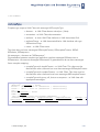
OVERVIEW
MagicDraw code engineering provides a simple and intuitive graphical interface for
merging code and UML models, as well as preparing both code skeletons out of UML
models and models from code.
MagicDraw code engineering implements several cases where code engineering may
by very useful:
•
You already have code that needs to be reversed to a model.
•
You wish to have the implementation of the created model.
•
You need to merge your models and code.
The tool may generate code from models and create models out of code (reverse).
Changes in the existing code can be reflected in the model, and model changes may
also be seen in your code. Independent changes to a model and code can be
merged without destroying data in the code or model.
MagicDraw UML code engineering supports Java, C++, CORBA IDL, DDL, XML
Schema, WSDL, and C# languages also EJB 2.0 UML notation is supported. You
may model EJB classes and generate descriptors for them. You may also reverse
descriptors and will get a model describing your Enterprise Java Beans. Your models
can be converted to any of those languages, or UML models can be created from the
source code written in those languages. Also reverse from Java Bytecode and CIL is
supported.
The Code Engineering Sets tool is MagicDraw tool managing center for all code
engineering matters.
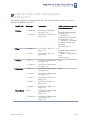
Code engineering is available only in Professional or Enterprise editions. In the
following table you’ll find what languages are supported in different editions:
Language
Professional Edition
Enterprise Edition
Java
Java
+
Java Bytecode
Java
+
C++
C++
+
CORBA IDL
-
+
DDL/Database
engineering
-
+
CIL
C#
+
© 2005 No Magic, Inc.
1-5
1
MagicDraw Code Engineering
Introduction
Language
Professional Edition
Enterprise Edition
CIL Disassembler
C#
+
XML Schema
-
+
WSDL
-
+
C#
C#
+
EJB 2.0
-
+
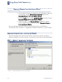
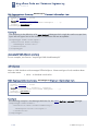
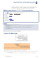
CODE ENGINEERING SETS
You may manage code engineering through the Code Engineering Sets in the
Browser tree. The Code Engineering Sets tree contains the list of all sets created in the
project and instruments for managing those sets.
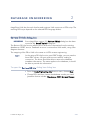
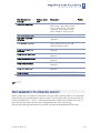
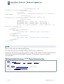
To add a new set
1
From the Code Engineering Sets shortcut menu, choose New.
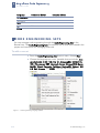
2
Choose the language you want. (possible choices include: Java,
Java Bytecode, C++, C#, CIL, CIL Disassembler, CORBA IDL,
DDL (Cloudscape, DB2, Microsoft Access, Microsoft SQL Server,
MySQL, Oracle, Pervasive, Pointbase, PostgreSQL, Sybase), EJB
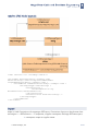
2.0, XML Schema, and WSDL). The new set is created.
Figure 1 -- Code engineering language options
1-6
© 2005 No Magic, Inc.
MagicDraw Code Engineering
Introduction
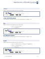
1
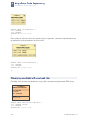
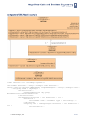
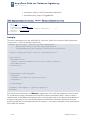
Edit sets in the Round Trip Set dialog box. To open this dialog box
•
Choose Edit from the set shortcut menu.
If you are performing round trip for the first time, the tip message box appears.
Figure 2 -- Code Engineering Sets tip message box
Disable the tip message box by deselecting the Show this tip next time check box.
© 2005 No Magic, Inc.
1-7
1
MagicDraw Code Engineering
Introduction
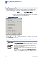
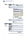
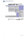
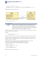
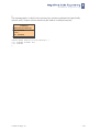
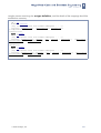
The Round Trip Set dialog box allows you to manage entities to be added/removed to
your set.
Figure 3 -- Round Trip Set dialog box. Add files tab
Specify Working Directory for displaying source files. This option indicates files and
required sub-directories, where a code generation output goes. Type a path manually or
by browsing in the directory tree, by clicking the ‘…’ button.
The Working Package option allows to define any package for reverse output or code
generation. Model will be reversed or code generated from this specified package.
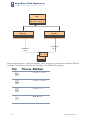
The Round Trip Set dialog box has two tabs: Add Files and Add Data from Model.
The Add Files tab helps you manage the files of source code involved in your code
engineering set.
1-8
Element name
Function
All files
Helps you find directories with the source files for the set.
Files of type
Contains possible file name extensions for the chosen language.
© 2005 No Magic, Inc.
MagicDraw Code Engineering
Introduction
1
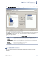
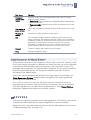
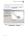
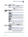
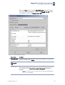
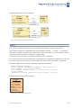
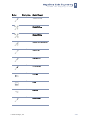
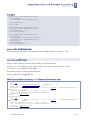
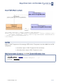
The Add Data from Model tab helps you manage elements located in the UML model.
Figure 4 -- Round Trip Set dialog box. Add data from model tab
The All Data list contains the hierarchy of UML model packages with model elements (or
other packages) inside of them. Your code engineering set can be combined out of
model and code elements.
The following buttons are available in the Round Trip Set dialog box:
Add
The selected file in the All Files or All Data list is added to the set.
Add All
All files in the opened or selected directory are added to the set.
Add Recursively
All files in the selected directory and its subdirectories are added to the
set.
Remove
Removes the selected entity from the set.
Remove All
Removes all entities from the set.
GENERATE CODE
You may generate code for the selected and prepared set and directly for model
elements.
© 2005 No Magic, Inc.
1-9
MagicDraw Code Engineering
Introduction
1
Code Generation for Set
Start code generation once the set or sets are prepared. For more details about
creating and editing sets, see Section “Code Engineering Sets” on page 1-6.
•
Choose Generate from the Code Engineering Sets item shortcut
menu. It allows code generating for all created sets.
•
Choose Generate from the selected set shortcut menu. It allows
code generating only for the selected set.
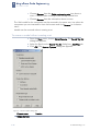
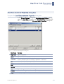
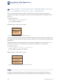
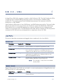
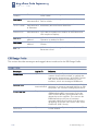
The Code Generation Options dialog box appears.
Figure 5 -- Code Generation Options dialog box.
The Code Generation Options dialog box allows you to specify the way your code
will be generated.
Once generating options are specified for the set, code can be generated.
Box name
Function
Output Directory Type the directory where the generated files will be saved.
1-10
'...'
The Set Output Directory dialog box appears. Select the directory
for the generated files.
Set as Working
Directory
The output directory is set as a working directory and files are
saved to the working directory.
Reverse before
generation
Changes your model according to changes in the existing code.
WARNING:
Exercise caution when selecting the Reverse before generation
check box. If the model differs from the code, all differences in the
model will be discarded. In such cases, you will lose some your
work.
© 2005 No Magic, Inc.
MagicDraw Code Engineering
Introduction
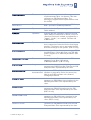
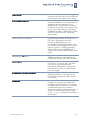
Box name
Function
If element
deleted from
model
To influence the structure of generated code, click one of the
following option buttons:
• Delete code. The representation of deleted entities will be deleted
from the code file.
• Comment code. Deleted entities will be commented in the code
file.
Use spaces in
place of tabs
When selected, spaces (instead of tabs) will be written to the code
file.
Number of
spaces
Specify the number of spaces to be written.
OK
The Messages Window appears, displaying how code files are
being generated. The Messages Window informs you of problems
and errors (mainly file access and syntax errors) found in the code
generation process and generation summary. You are also
prompted to confirm that you wish to overwrite the file if the
output directory already contains one with the same name.
Cancel
Closes the dialog box without saving changes.
Help
Displays MagicDraw Help
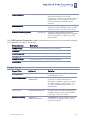
1
Code Generation for Model Element
All the classes contained in the component will be written to one file. However, code
for the class can be generated in a different way. Select the class you wish to generate
in the browser Data package and click Generate in the class shortcut menu. For
packages and components, you may also select Generate, but you will not be able to
specify the generation options. All the options related to that task will be set
according to the default values.
If you have chosen framework generation for a single class or for packages, the
Code Generation Options dialog box does not appear. The code is generated
according to the default values.
If no errors occurred, you may view the results with your favorite file viewer or
programming environment. Look for the files in the directory that you specified as
your Working directory in the Round trip set dialog box or in the Project Options
dialog box. Additional sub-directories could be created.
REVERSE
A reverse is an opposite operation to the code generation. The existing code can be
converted to UML models with the help of MagicDraw reverse mechanism.
Prepare the sets in the exact same way that you did for code generation (see Section
“Code Engineering Sets” on page 1-6)
© 2005 No Magic, Inc.
1-11
MagicDraw Code Engineering
Introduction
1
•
Choose Reverse from the Code engineering sets item shortcut
menu. It allows code reversing for all already created sets.
•
Choose Reverse from the selected set shortcut menu.
The UML model for the component can be reversed in the same way. Just select the
component you are interested in from the browser and click Reverse on it shortcut
menu.
Models can be reversed without creating a set.
To reverse a model without creating a set
1
2
3
From the Tools menu, choose Quick Reverse. The Round Trip Set
dialog box appears.
Select the files from the Round Trip Set dialog box, Add Files tab.
Click OK. The Reverse Options dialog box appears.
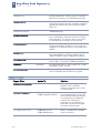
Figure 6 -- Reverse options dialog box
Element name
Function
VIZUALIZATION
1-12
© 2005 No Magic, Inc.
MagicDraw Code Engineering
Introduction
Element name
Function
Visualize reversed
model
Classes that are created while reversing can be added to a
diagrams.
Launch Model
Visualizer
After reversing, the Model Visualizer dialog box appears. It
will assist you in creating a class diagram or sequence
diagram (Java only) for newly created entities.
Create new class
diagram
After reversing, the Create Diagram dialog box appears.
Create a new diagram where the created entities will be
added.
1
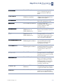
Add to active diagram After reversing, all created entities will be added to the
current opened diagram.
GENERAL
Look for classes in
classpath
Search for classes in the classpath while reversing is
executed.
CREATE CLASS FIELDS AS
Attributes
Class fields are represented in model as attributes.
Associations
Class fields are represented in model as association ends.
Reset already created
fields
Select this option if you want to keep already created UML
representation (attribute or association) for class fields.
MODEL REFRESH TYPE
Merge model and
code
The model elements are updated by code. Elements that do
not exist in the code will not be removed from the model.
Change model
according to code
Model will be created strictly by code. Entities in the model
that do not match entities in the code will be discarded.
OK
Saves changes and exits the dialog box.
Cancel
Exits dialog box without saving changes.
Help
Displays MagicDraw Help.
If you have a code set combined from several files, you may see changes you wish to
model without reversing all the code. Only changed files should be reversed. This
type of reversing can be done by clicking the Refresh button on the set shortcut menu,
or by performing model refresh from the Code Engineering Sets dialog box.
JAVA REVERSE TO SEQUENCE DIAGRAM
Java reverse to Sequence diagram functionality allows visualizing Java method
implementation with UML Sequence diagram. Created from method Sequence
diagram cannot be updated, every time new diagram should be generated.
© 2005 No Magic, Inc.
1-13
MagicDraw Code Engineering
Introduction
1
To launch Sequence Diagram from Java Source Wizard and specify options
needed for the reverse
•
You are able to reverse any operation from the Browser: right click
an operation, choose Reverse Implementation and launch
Sequence diagram from Java Source Wizard.
•
From the Tools menu, choose Model VIsualizer, and then choose
Sequence Diagram from Java Source WIzard.
•
When reversing, in the Reverse Options dialog box, choose
Launch Model Visualizer and then choose Sequence Diagram
from Java Source Wizard.
The more detailed example of how this functionality works, see MagicDraw
Tutorials.pdf, which is locate in <MagicDraw installation directory>, manual folder.
Sequence Diagram from Java Source Wizard
Sequence Diagram from Java Source Wizard is the primary tool for reversing s
sequence diagram from Java method. It contains four steps that are described below.
STEP 1 SPECIFY NAME
AND
PACKAGE.
Figure 7 -- Sequence Diagram from Java Source Wizard
1-14
© 2005 No Magic, Inc.
MagicDraw Code Engineering
Introduction
1
In this step, type the name of the newly created sequence diagram. Be default class
name and selected operation name with a word “implementation” will be included in the
sequence diagram name.
Also choose the package that will contain created sequence diagram. If you want to
create a new package and place there a sequence diagram, click the New button and
define package parameters in the Package Specification dialog box.
STEP 2 SELECT OPERATION
In this step, select an operation for which you want to create a sequence diagram. If the
Java source file is not shown you must select it manually.
IMPORTANT To specify implementation files, we suggest, before reversing, to specify
Java Default working directory in the Project Options dialog box
(specify root folder where all source files can be found).
© 2005 No Magic, Inc.
1-15
MagicDraw Code Engineering
Introduction
1
STEP 3 SELECT CLASSES
FOR
DIAGRAM
In the Select Classes for Diagram step, all referenced classes are displayed. Select the
desired classes and instances of those classes will be added into diagram with call
messages to them.
1-16
•
Select the Analyze and split long expressions in diagram check
box if expression contains calls and cannot be displayed as call
message. Then every call will be shown as separate call message
with temporary variable initialization.
•
Select the Create return message check box, if you want to display
return message for every call message.
•
Select the Wrap message text check box and specify the maximum
message text length in pixels, to wrap longer message.
© 2005 No Magic, Inc.
MagicDraw Code Engineering
Introduction
1
STEP 4 SPECIFY SYMBOLS PROPERTIES
Figure 8 -- Sequence Diagram from Sequence Wizard. Specify Symbols Properties
In this step, define symbols properties for lifelines and messages.
© 2005 No Magic, Inc.
1-17
1
MagicDraw Code Engineering
Introduction
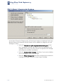
GLOBAL OPTIONS FOR CODE
ENGINEERING
Code engineering options for all sets in your project
From the Options menu, choose Project. The Project Options dialog box appears.
Figure 9 -- Project Options dialog box
The Project Options dialog box has two main collections of customizable options, which are
represented by the hierarchy tree on the left side of the dialog box:
•
Styles – expands the tree hierarchy of all the styles defined within the
project. You may use as many of these styles as you wish. See MagicDraw
main User’s Manual, working with Projects Section.
•
Code engineering – these options are found on the right side of the
Project options dialog box:
•
1-18
Default Working Directory field - type the name or browse by clicking
the button in the working directory.
© 2005 No Magic, Inc.
MagicDraw Code Engineering
Introduction
•
Default Working Package - allows to define any package for
reverse output or code generation. Model will be reversed or
code generated from this specified package.
•
Default Paths for References - add specific profiles, modules,
libraries to define where to search paths for references during
revers/code generation.
•
Default Encoding - a list of available encodings appears.
•
Default language drop-down box – select the default generation
language.
•
Use Syntax Checker check box – when selected, the syntax
checker runs while Code Engineering is executed
•
Directory for Temporal Files - it can be Active Directory, System
or define other by clicking “...” button..
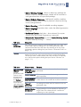
Tab name
Description
Code
generation
Set code generation options using the fields listed in the right side
of the Project options dialog box. The Code generation area
contains boxes that have the same functionality as in the Code
generations options dialog box (see Section “Generate Code” on
page 1 -9).
Reverse
Set reverse options for all reverse actions of the project using the
options listed on the right side of the Project options dialog box.
The Reverse area contains boxes that have the same functionality
as in the Reverse options dialog box (see Section “Reverse” on
page 1 -11).
Tab name
Element name
Function
Java Language
Options
Set the
generated code
style for Java
programming
languages in
the Default
language field
found on the
right side of the
Project Options
dialog box.
Generate
opening bracket
in new line
Opens a bracket in the new line that is being
generated.
© 2005 No Magic, Inc.
1
Generate spaces Generates spaces inside an assignment and
other operators.
Generate empty
documentation
Comment brackets are placed in your code,
unless class in the model has no documentation.
Automatic
“import”
generation
Automatic generation of "import" sentences
according to classes that are referenced in the
generated class.
Class count to
generate import
on demand
Specify number of classes imported from a
single package until all statements importing a
single class are substituted with a statement
importing an entire package.
1-19
1
MagicDraw Code Engineering
Introduction
Tab name
Element name
Function
Documentation
Processor
After selecting Java Doc processor, click the “...”
button to open the Documentation Properties
dialog box.
Style
Two styles are available for documentation.
Use CLASSPATH
The ’...’ button is activated. Search a classpath
for importing sentences generation in the Set
classpath dialog box.
Figure 10 -- Set classpath dialog box
Click the Get from System button to get
CLASSPATH variable defined by operating
system or click the Add button and select the
classpath directory in the Add Classpath dialog
box.
C++ Language
Options
Set the
generated code
style for C++
programming
languages.
Java Source
Available choises 1.4 or 5.0
Header
Add the specific header to all your code files.
Click the button and enter header text in the
Header screen.
You may also define $DATE, $AUTHOR, and
$TIME in the header.
Generate
opening bracket
in new line
Opens a bracket in the newly generated line.
Generate spaces Spaces inside an assignment and other
operators are generated.
Generate empty
documentation
Comment brackets are placed in your code,
unless class in the model has no documentation.
Generate
methods body
into class
Select check box to generate methods body into
class.
Documentation
Style
Two styles are available for documentation.
Use include path Select check box. The ’...’ button is activated.
Click the ’...’ button and then specify the path
for the includes in the Set Include Path dialog
box.
1-20
© 2005 No Magic, Inc.
MagicDraw Code Engineering
Introduction
Tab name
CORBA IDL 3.0
Language
Options
1
Element name
Function
Use explicit
macros
Select check box. The ’...’ button is activated,
click it and in the C++ Macros dialog box use a
set of predefined macros.
Header
Add the specific header to all your code files.
Click the “…” button and enter header text in
the Header screen.
You may also define $DATE, $AUTHOR, and
$TIME in the header.
Generate
documentation
Includes the documentation of an element in the
comment.
Generate
opening bracket
in new line
Opens a bracket in the new line generating.
Generate spaces Spaces inside an assignment and other
operators are generated.
DDL Language
Options
Generate empty
documentation
Comment brackets are placed in your code,
unless class in the model has no documentation.
Generate
imports
Generation of "import" statements for classes
that are referenced in the generated class.
Generate
preprocessor
directives
Generates pre-processors directives.
Documentation
Style
Three styles are available for documentation.
Header “...”
Add the specific header to all your code files.
Click the “...” button and enter header text in the
Header screen. You may also define $DATE,
$AUTHOR, and $TIME in the header.
Set Include Path
Specify the path for the "includes". Click the "..."
button to open the Select Folder dialog box.
Generate
opening bracket
in new line
Opens a bracket in the new line generating.
Generate spaces Spaces inside an assignment and other
operators are generated.
© 2005 No Magic, Inc.
Generate
documentation
Comment brackets are placed in your code,
unless class in the model has no documentation.
Header
Add the specific header to all your code files.
Click the button and enter header text in the
Header screen. You may also define $DATE,
$AUTHOR, and $TIME in the header.
1-21
1
MagicDraw Code Engineering
Introduction
Tab name
Element name
Function
C# Language
Options
Set the
generated code
style for C#
programming
languages.
Generate
opening bracket
in new line
Opens a bracket in the newly generated line.
Generate spaces Generates spaces inside an assignment and
other operators.
Generate empty
documentation
Comment brackets are placed in your code,
unless class in the model has no documentation.
Generate
required "using"
directives
Automatic generation of "using" directives. This
option facilitates the usage of namespaces and
types defined in other namespaces.
Concatenate
namespace
names
If not selected namespace names are separated
into several lines.
e.g.
namespace A
{
namespace B
{
Documentation:
• Processor
•
1-22
Style
•
•
Use C# XMI processor then generates c# xmi
documentation for commenting the code.
Select one of the listed comment styles.
Header
Adds the specific header to all your code files.
Click the '...' button and type header text in the
Header dialog box.
You may also define $DATE, $AUTHOR, and
$TIME in the header.
Conditional
Symbols
Add the conditional symbols, which can not be
recognized and should be skipped during
reverse.
Click the '...' button and add conditional
symbols in the Define Conditional Symbols
dialog box.
© 2005 No Magic, Inc.
MagicDraw Code Engineering
Introduction
1
Java Documentation Properties dialog box
To open the Java Documentation Properties dialog box
In the Project Options dialog box, Java Language Options group,
select the Java Doc processor in the Documentation field and click
the “...” button to open the Documentation Properties dialog box.
Figure 11 -- Documentation Properties dialog box
Box Name
Function
Tag Name
Type a tag name.
Value
Type the value of the tag.
Generate
The selected tag will be placed in the generated code as a comment
before classifier (class or interface), operation or attribute.
Up
Moves the selected item up the list.
Down
Moves the selected item down the list.
Add
Adds a new item in the list.
Remove
Removes the selected item from the list.
OK
Saves changes and closes the dialog box.
Cancel
Closes the dialog box without saving changes.
Help
Displays MagicDraw Help.
© 2005 No Magic, Inc.
1-23
MagicDraw Code Engineering
Introduction
1
Round Trip
MagicDraw round trip keeps your code and model synchronized, and because Round
trip traces all the model and code changes, you may freely change entity
specifications without discarding code changes made outside the tool.
For example, Round Trip prevents a job from being damaged by code additions or
changes when these steps are followed:
Within the tool, class Base is created.
Operation getInstance is added to class.
2 Code is generated
3 With external tool, programmer adds code to that operation.
4 With MagicDraw UML, operations name is changed to Instance.
5 Code is generated.
If the tool rewrites the whole code, these changes are made without corrupting the
programmer’s job. The name of the operation is changed, but the internals remain
the same.
1
Round trip catches all changes in your project and controls the following
actions:
1-24
•
If the source code is not changed, it is not allowed to refresh UML
model. The Refresh command from the set shortcut menu is
unavailable.
•
If the model is changed but the code remains the same (new
members were added or their headers were changed), refresh is
not allowed, and the Refresh command from the set shortcut
menu is unavailable. When generating code according to
changes, all changes in the model are written to the signatures of
class members, leaving the old implementation in place.
•
If the code is changed but the model remains the same, refresh
can be executed: code will be reversed to the UML models. If the
Code Generation Options dialog box appears when you are
attempting to generate code, you may select a code action that
differs from the UML model.
•
If the code and model are changed while refreshing, all changes
in the code are treated as new items and added to the model.
•
If data in the model file is deleted, it will be restored while
refreshing, even when the code has not been changed or the data
itself is unimportant.
© 2005 No Magic, Inc.
MagicDraw Code Engineering
Introduction
1
Type Mapping Table
Languages supported by MagicDraw UML have their own built-in types. One
language’s type might have no matches in another language, or it might have
multiple matches. Additionally, some names are interpreted differently in different
languages. When performing code generation, therefore, problems may occur when
switching between different languages. To avoid this, MagicDraw UML uses typemapping tables to manage mapping between languages. It describes the rules of
how one language’s built-in types are converted to those of another language
FILES OF PROPERTIES
The code can be generated out of prepared UML models. The mapping between the
identifiers, used in the UML model and the language to which the model is being
generated, should be implemented. This mapping includes the following sections:
•
Build-in types (their default values)
•
Generalization types
•
Possible class declarations. Attributes and operations declaration
and visibility modifiers
•
Code generation options.
The separate prop file is created for every language that is supported by MagicDraw.
Files are located in the <MagicDraw installation directory>/data folder. The file
name pattern is lang.prop, where lang stands for the name of the programming
language.
Supported
language
File of Properties
JAVA
java.prop
C++
C++.prop
CORBA IDL
idl.prop
JAVABytecode
javabytecode.prop
DDL
ddl.prop
CIL
cil.prop
CIL Disassembler
cil disassembler.prop
C#
c#.prop
EJB
ejb.prop
EJB 2.0
ejb20.prop
IDL
idl.prop
© 2005 No Magic, Inc.
1-25
MagicDraw Code Engineering
Introduction
1
Supported
language
File of Properties
XML Schema
xmlschema.prop
WSDL
wsdl.prop
Files of language properties are separated into sections where all related elements
are grouped. You may edit existing entities, add new ones, and change the default
values.
We strongly recommend that you edit default values only. In general, all the sections
have the list of possible and default values for the element.
1-26
© 2005 No Magic, Inc.
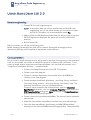
DATABASE ENGINEERING
2
MagicDraw UML has the tools that forward engineer UML constructs to DDL script. The
resulting DDL script depends on the selected DDL language dialect.
Retrieve DB Info dialog box
IMPORTANT!
Since MagicDraw version 9.0, Retrieve DB Info dialog box has been
moved to the Round Trip Set dialog box.
The Retrieve DB info function allows you to retrieve the information from the existing
database or ODBC source. Database structure is retrieved as UML model, using class
diagram elements.
The mapping of the DB to UML is the same as in DDL reverse engineering.
NOTE
As the retrieve DB info function uses JDBC bridge, you may need to
have JDBC drivers. All types of drivers are valid for making a
connection. The driver should be able to retrieve the database
metadata information. The same applies to the database; it should
be able to provide this information.
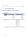
To open the Retrieve DB Info dialog box dialog box
© 2005 No Magic, Inc.
1
From the Code Engineering Sets shortcut menu, choose New.
2
Choose DDL and then choose the database vendor you need.
(possible choices include: Cloudscape, DB2, Microsoft Access,
2-27
2
MagicDraw Code Engineering
Database Engineering
Microsoft SQL Server, MySQL, Oracle, Pervasive, Pointbase,
PostgreSQL, Standard SQL, and Sybase.
2-28
3
The new set is created.
4
From the created set shortcut menu, choose Edit. The Round Trip
Set dialgo box appears. Select the Reverse from DB option.
© 2005 No Magic, Inc.
MagicDraw Code Engineering
Database Engineering
•
2
From the Tools menu, choose Quick Reverse and then choose
DDL and required database vendor. The Round Trip Set dialgo
box appears. Select the Reverse from DB option.
Figure 12 -- Retrieve DB Info dialog box
Box name
Function
Recently Used
Contains the list of the recently used reverse templates. Choose the
one you need and click Apply.
DB
Connection
URL
The connection URL for the selected profile.
Driver Files
Contains .jar and .zip files or directories with JDBC driver’s classes.
To choose the files or directories you want to add or remove, click
the “...” button. The Select Files and/or Directories dialog box
appears.
NOTE If the driver file is empty, Driver Class is searched from
the classpath.
© 2005 No Magic, Inc.
2-29
2
MagicDraw Code Engineering
Database Engineering
Box name
Function
Driver Class
Contains the connection driver class.
Click the “...” button and the list of available driver classes that are
available in the selected driver files is displayed.
NOTE Only in the files that are selected in the Driver Files list,
the system searches for driver classes .
Username
Type the username to connect to the database.
Password
Type the password to connect to the database.
Catalog
Contains a name of the selected Catalog.
To retrieve the list of available Catalogs from the database, click the
“...” button and select the catalog. The catalog name appears in the
Catalog text box.
NOTE Only when all other properties in this dialog box are
correctly defined, the list of catalogs can be retrieved.
Schema
Contains a name of the selected Schema.
To retrieve the list of available Schemas from the database, click the
“...” button and select the schema. The schema name appears in the
Schema text box.
NOTE Only when all other properties in this dialog box are
correctly defined, the list of schemas can be retrieved.
Property
Name
The name of the JDBC driver property.
NOTE: If using Oracle drivers, while retrieving db info from Oracle
db:
• To retrieve comments on table and column, set property as
remarks=true.
• To connect to a db as sysdba, set property as
internal_logon=sysdba.
Debug JDBC
Driver
If selected, all output from a JDBC driver will be directed to Message
Window.
Relode Driver
By default, the Reload Driver check box is selected. If you want that
driver to not be reloaded, clear the check box.
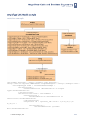
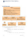
FORWARD ENGINEERING TO DDL SCRIPT
This section describes to what data model constructs MagicDraw constructs are
converted.
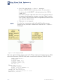
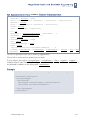
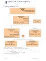
Packages
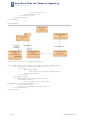
The Database is represented as a Package with the <<database>> stereotype. Each
View or Table can be assigned to a Schema where the Schema is represented as a
Package with the <<schema>> stereotype.
2-30
© 2005 No Magic, Inc.
MagicDraw Code Engineering
Database Engineering
2
A Package, depending on a package stereotype, is mapped to one of the following DDL
constructs:
•
A Database, if the package has the <<database>> stereotype.
Elements: CREATE DATABASE <database_name>
Database name is equal to the package name.
•
A Schema, if the package has the <<schema>> stereotype.
Elements: CREATE SCHEMA
[<database_name>.]<schema_name>
Schema name is equal to the package name. Schema database
name is the name of a package that contains schema package.
•
Otherwise it is not mapped.
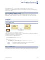
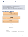
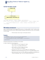
If a package has no stereotype and the EnableDefaultStereotypes
property is true, the <<database>> stereotype is used for the first
level packages, and the <<schema>> stereotype is used for the
second level packages.
NOTE
<<database>>
DB1
<<schema>>
<<schema>>
Schema1
Schema2
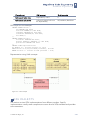
Figure 13 -- Package mapping example
DLL script, generated for example showed in Package mapping example12, creates one
Database and two Schemas:
CREATE DATABASE DB1;
CREATE SCHEMA DB1.Schema1;
CREATE SCHEMA DB1.Schema2;
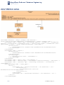
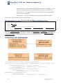
Classes
A class, depending on class stereotype, is mapped to one of the following DDL
constructs:
•
© 2005 No Magic, Inc.
Table, if the class has the <<table>> stereotype.
Elements: CREATE TABLE [<schema_name>.]<table_name>
(<column_and_constraint_list>)
Table name is equal to the class name. Table schema name is the
name of package that contains table class.
2-31
2
MagicDraw Code Engineering
Database Engineering
NOTE
•
View, if the class has the <<view>> stereotype.
Elements: CREATE VIEW [<schema_name>.]<view_name>
[(<column_list>)] AS SELECT <derived_column_list> FROM
<table_list>.
View name is equal to the class name. The view schema name is
the name of a package that contains view class. Table list within
view “FROM” clause are derived from dependencies between the
view class and tables classes.
•
Otherwise it is not mapped.
If a class has no stereotype and the EnableDefaultStereotypes
property is true, the class is treated as a class with the <<table>>
stereotype.
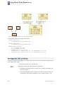
Figure 14 -- Class mapping example
DLL script, generated for classes is showed in Class mapping example. It has two Table
definition statements (CREATE TABLE) and view definition statement (CREATE VIEW):
CREATE TABLE Person (
id integer,
socialId number (10),
lastName varchar (20),
firstName varchar (10),
sex char (1)
);
CREATE TABLE Account (
accountNo integer,
balance float (5) DEFAULT 0.0,
personalId integer);
CREATE VIEW ImportantClient
AS SELECT P.*, Account.balance as total
FROM Person, Account;
2-32
© 2005 No Magic, Inc.
MagicDraw Code Engineering
Database Engineering
2
Attributes
An attribute of a class with the <<table>> or the <<view>> stereotype, depending
on an attribute stereotype, is mapped to one of the following DDL constructs:
•
A Column of a Table, if the class that contains an attribute has the
<<table>> stereotype.
A Column name is equal to the name of an attribute. A Column
type is equal to the type of an attribute. Column default value is
equal to the initial value of an attribute (if any).
•
A Column of a View, if the class that contains an attribute has the
<<view>> stereotype.
Elements: [<column_expression> AS] <column_name>
A Column name is equal to the name of an attribute. Column
expression is equal to the initial value of an attribute (if any).
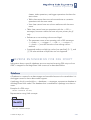
Figure 15 -- Attributes mapping example
Col1 attribute of the Table1 class (see Attributes mapping example14) is mapped to the
col1 column of a Table1 table, and col1 attribute of the View1 class is mapped to the
col1 column of a View1 view. There is DDL script for attributes mapping example:
CREATE TABLE Table1 (
col1 integer DEFAULT 123
);
CREATE VIEW view1
AS SELECT Table1.col1 AS v1
FROM Table1;
Operations
An operation (method) of a class with the <<table>> stereotype, depending on an
operation’s stereotype, is mapped to one of the following DDL constructs:
•
© 2005 No Magic, Inc.
An Index for a Table, if the operation has the <<index>>
stereotype;
Elements: CREATE INDEX [<schema_name>.]<index_name>
ON <table_name>(<column_list>)
An Index name is equal to the name of an operation. Names of
comma-delimited set of column for the index are equal to the
parameter names of an operation.
2-33
2
MagicDraw Code Engineering
Database Engineering
NOTES:
•
Tags with names: trigger action time, trigger event and triggered
action has meaning in DDL CG have meaning in the DDL CG if
are specified for an operation with stereotype <. The
"implementation" tag specified for operation with stereotype
trigger has no meaning for the DDL code generation since MD
6.0 version. The "implementation" tag was split to three tags:
"trigger action time", "trigger event" and "triggered action". Values
of these tags will be used then generating definition of a trigger.
::= CREATE TRIGGER ON [ REFERENCING ]
•
A constraint, if the Operation has the <<PK>>, <<unique>>,
or <<check>> stereotype.
Elements: [ALTER TABLE <table_name> ADD] CONSTRAINT
<constraint_name>
Constraint name is equal to the name of an operation.
•
PRIMARY KEY (<pk_column_list>)
Primary key column list contains all attributes with the <<PK>>
stereotype.
•
UNIQUE (<unique_column_list>)
Unique constraint element <unique_column_list> is generated
from operation’s parameter names.
•
CHECK (<check_expression>)
Check constraint element <check_expression> is generated
from tag named Implementation.
Otherwise it is not mapped.
IndexNamePrefix property specifies an optional naming standard
that is added to the beginning of the name for each generated
index.
TriggerNamePrefix property specifies an optional naming standard
that is added to the beginning of the name for each generated
trigger.
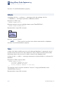
Figure 16 -- Operations mapping example
An example of the DDL script for operations mapping:
2-34
© 2005 No Magic, Inc.
MagicDraw Code Engineering
Database Engineering
2
CREATE TABLE TableB (
id integer
CONSTRAINT checkColumn CHECK(/*<check_expression>*/),
b1 integer,
b2 integer,
CONSTRAINT pk1 PRIMARY KEY (id),
CONSTRAINT checkTable CHECK(/*<check_expression>*/),
CONSTRAINT unique1 UNIQUE(b1,b2)
);
CREATE TABLE TableA (
fk integer,
a1 integer DEFAULT 123,
CONSTRAINT fk1 FOREIGN KEY (fk) REFERENCES TableB(id)
);
CREATE INDEX indexOnA1 ON TableA(a1);
CREATE TRIGGER trigger1 ON TableA /*<triggered_SQL_statement>*/;
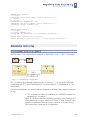
Relationship cardinalities
ONE-TO-MANY (1:N)
RELATIONSHIP
One-to-many (1:N) relationship is mapped to dependency with <<FK>> stereotype.
A
cb
ca
B
Figure 17 -- Cardinalities of 1:N relationship
For 1:N relationship allowed cardinalities for end A are 0, 1, N. For end B allowed
cardinalities are 0, 1 (see Cardinalities of 1:N relationship16 -- Cardinalities of 1:N
association).
Concrete cardinalities of A and B ends are mapped to different data model constraints
(if any):
If A end does not allow N cardinality, the UNIQUE constraint is
assigned to b_id column.
When b_id column has the UNIQUE constraint, every instance of A
class references a unique instance of B class (if any). Given B class
instance is associated with the unique instance of A class (if any).
This means that A end has no N cardinality.
1
© 2005 No Magic, Inc.
2-35
2
MagicDraw Code Engineering
Database Engineering
If B end does not allow 0 cardinality, NOT NULL constraint is
assigned to b_id column.
When b_id column has NOT NULL constraint, every A class
references some B class. This means that ca role does not allow 0
cardinality.
2
Employee
1..*
1
Company
Figure 18 -- 1:N relationship and mapped representation
Script creating 1:N relationship:
CREATE TABLE Company (
id INTEGER NOT NULL PRIMARY KEY);
CREATE TABLE Employee (c_id INTEGER NOT NULL,
CONSTRAINT FK_1 FOREIGN KEY (c_id) REFERENCES Company (id));
ONE-TO-ONE (1:1)
RELATIONSHIP
One-to-one (1:1) relationship is handled as a special case of one-to-many relationships,
where end B allowed cardinalities are 0, 1 and end A allowed cardinalities are 0, 1 (see
Cardinalities of 1:N relationship16 -- Cardinalities of 1:N association).
1:1 relationship is mapped to a dependency with <<FK>> stereotypey. The 1:1
cardinality must be forced through constraints.
Director
1
1
Company
Figure 19 -- 1:1 relationship and mapped representation
A script that creates a 1:1 relationship:
CREATE TABLE Company (
id INTEGER NOT NULL PRIMARY KEY
);
CREATE TABLE Director (
c_id INTEGER NOT NULL UNIQUE,
CONSTRAINT FK_1 FOREIGN KEY (c_id) REFERENCES Company (id)
2-36
© 2005 No Magic, Inc.
MagicDraw Code Engineering
Database Engineering
2
);
Nevertheless, this DDL script with these constrains does not ensure a strict 1:1
relationship – Company table may have rows that do not have their counterpart rows
within Director table.
MANY-TO-MANY (N:M)
RELATIONSHIP
Many-to-many (N:M) associations are not handled by MagicDraw UML. The N:M
relationship can be achieved by using two 1:N relationships with intermediate table.
Inheritance
SINGLE
INHERITANCE
Employee
Director
Figure 20 -- Single Inheritance and mapped representation
Single inheritance can be modeled with the 1:1 relationship, by creating the foreign key
constraint on primary key in the derived class.
A script that creates a single inheritance:
CREATE TABLE Employee (
id INTEGER NOT NULL PRIMARY KEY
);
CREATE TABLE Director (
id INTEGER NOT NULL PRIMARY KEY,
CONSTRAINT FK_1 FOREIGN KEY (id) REFERENCES Employee(id)
);
NOTE
MULTIPLE
The Employee table may have rows that do not have their
counterpart rows within Director table.
INHERITANCE
The mapping of a multiple inheritance is similar to the mapping of a single inheritance.
© 2005 No Magic, Inc.
2-37
2
MagicDraw Code Engineering
Database Engineering
Base1
Base2
Derived
Figure 21 -- Multiple Inheritance and mapped representation
A script that creates a multiple inheritance:
CREATE TABLE Base1 (
id INTEGER NOT NULL PRIMARY
);
CREATE TABLE Base2 (
id INTEGER NOT NULL PRIMARY
);
CREATE TABLE Derived (
b1_id INTEGER NOT NULL,
b2_id INTEGER NOT NULL,
PRIMARY KEY (b1_id, b2_id),
CONSTRAINT FK_1 FOREIGN KEY
CONSTRAINT FK_2 FOREIGN KEY
);
KEY
KEY
(b1_id) REFERENCES Base1(id),
(b2_id) REFERENCES Base2(id)
Not supported UML constructs
Constructs that are not mapped into DDL script, because this would lead to a generation
of an illegal DDL code:
•
NOTE
2-38
Duplicated names are not allowed.
Uppercase and lowercase letters are equivalent.
•
Database package cannot contain two schema packages with
the same name.
•
Schema package cannot contain two UML constructs that are
mapped to the schema elements such as table classes, view
© 2005 No Magic, Inc.
MagicDraw Code Engineering
Database Engineering
2
classes, index operations, and trigger operations that have the
same name.
•
Table class cannot have two column attributes or constraint
operations with the same name.
•
View class cannot have two column attributes with the same
name.
•
Table class cannot have two operations with the <<PK>>
stereotype, because a table can have only one primary key (if
any).
•
References to non-existing columns are illegal.
•
•
The parameter name of an operation with a DDL stereotype
(<<index>>, <<trigger>>, <<PK>>, <<unique>>,
<<check>>) must be the name of an existing column
attribute.
Supported attribute multiplicity can be [not specified], [0..1], and
[1]. All other attribute multiplicities are not supported.
REVERSE ENGINEERING FOR DDL SCRIPT
Information about a specific database structure acquired reversing DDL script or from
JDBC is mapped to the MagicDraw UML constructs as described bellow.
Database
A Database is a system for a data storage and controlled access to the stored data. It is
the biggest construct that a data model supports.
A package, which is used with the <<database>> stereotype, represents a database in
the MagicDraw UML model. The database that is modeled as a package must have a
name.
Example of a DDL script:
CREATE DATABASE BankDB;
Representation using UML concepts:
<<database>>
BankDB
Figure 22 -- Database example
© 2005 No Magic, Inc.
2-39
MagicDraw Code Engineering
Database Engineering
2
See also: CurrentDatabaseName property
Schema
A package with the <<schema>> stereotype within the package with the
<<database>> stereotype represents a database schema.
Example of a DDL script:
CREATE SCHEMA Public;
Example rewritten using a qualified schema name “BankDB.Public”:
CREATE SCHEMA BankDB.Public;
Representation using UML concepts:
<<schema>>
Public
(BankDB)
Figure 22 – Schema example
NOTE
There can be more than one schema associated to a database.
See also: CurrentSchemaName property
Table
A table is the basic modeling structure of a relational database. It represents a set of
records of the same structure, also called rows. Each of these records contains data.
Information about the structure of a table is stored in the database itself.
A class with the <<table>> stereotype represents a relational table in a schema of a
database.
Example of a DDL script for table:
CREATE TABLE Account (
accountNo INTEGER NOT NULL,
personId INTEGER NOT NULL,
balance FLOAT(5) DEFAULT 0.0 NOT NULL
);
This example may be rewritten instead of “Account” using qualified table name
“BankDB.Public.Account”.
Representation using UML concepts:
2-40
© 2005 No Magic, Inc.
MagicDraw Code Engineering
Database Engineering
2
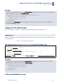
<<table>>
Account
(BankDB.Public)
-accountNo : INTEGER
-balance : FLOAT (5) = 0.00
-personId : INTEGER
Figure 23 -- Table example
Hosting the table in the schema package creates an association of a table to a schema.
Column
A table contains columns. A column must have a defined name and data type; a default
value and several constraints are optional.
Example: balance FLOAT(5) DEFAULT 0.0
A column is represented as an attribute. A name, data type, and initial value of an
attribute are set according to the name, data type, and default value of the column.
The stereotype of an attribute is set according to column constraints. Stereotype can be
not specified, <<unique>>, or <<PK>>.
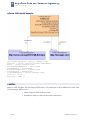
Constraint
A constraint is a rule applied to the structure of a database. This rule extends the
structure of a database and can be applied to a column or a table.
In general, a constraint may be represented as an operation with an appropriate
stereotype and parameter list containing the list of column names that constraint
concerns. An operation name is equal to the name of a constraint, but, when a
constraint has no name specified, operation is unnamed.
All listed constraints (null, not null, uniqueness, primary key, foreign key, and check) are
implemented in the following example:
CREATE TABLE Person (
id INTEGER NOT NULL PRIMARY KEY,
socialId NUMBER(10) NOT NULL UNIQUE
CONSTRAINT checkSocialId CHECK(socialId>0),
lastName VARCHAR(20) NOT NULL,
firstName VARCHAR(10) NOT NULL,
sex CHAR(1) NULL
);
CREATE TABLE Account (
accountNo INTEGER NOT NULL,
balance FLOAT(5) DEFAULT 0.0 NOT NULL
CONSTRAINT checkBalance CHECK(balance>=0),
© 2005 No Magic, Inc.
2-41
2
MagicDraw Code Engineering
Database Engineering
personalId INTEGER NOT NULL,
CONSTRAINT PK_Account0 PRIMARY KEY (accountNo, personalId),
CONSTRAINT FK_Account1 FOREIGN KEY (personalId) REFERENCES Person(id)
);
Representation using UML concepts:
Figure 24 -- Constraints example
NOT
NULL,
NOTE
NULL
A Null constraint is not defined in SQL-92 standard but some
dialects use it. Microsoft SQL Server allows setting a flag, which
indicates that all columns have Not Null constraint, which is set by
default. A Null constraint that is assigned for a column overrides the
default Not Null constraint and allows null values.
Not Null constraint indicates that the value for an attribute is required; Null constraint
indicates that the value is optional.
Example:
firstName VARCHAR(10) NOT NULL,
sex CHAR(1) NULL
Not null constraint and null constraint are modeled as the multiplicity of an attribute.
Multiplicity may be indicated by placing a multiplicity indicator in brackets after the
name of an attribute. A multiplicity of 0..1 provides a possibility of null values, for an
example: sex [0..1]: CHAR(1)
In the absence of a multiplicity indicator, an attribute holds exactly one value.
See also: ColumnDefaultNullability, AttributeDefaultMultiplicity,
GenerateNullConstraint, GenerateNotNullConstraint properties.
Example of a DDL script:
CREATE TABLE NullableExample (
dontcare INTEGER,
optional INTEGER NULL,
required INTEGER NOT NULL
);
Representation using UML concepts:
2-42
© 2005 No Magic, Inc.
MagicDraw Code Engineering
Database Engineering
2
Figure 25 -- Not null, null constraints example
UNIQUENESS
Uniqueness constraint indicates that the value of a column must be unique within the
table.
Uniqueness constraint is modeled as the <<unique>> stereotype applied to an
attribute and/or operation with the <<unique>> stereotype and a parameter list.
Example of a DDL script:
CREATE TABLE UniqueExample (
col1 INTEGER CONSTRAINT uniqueColumn UNIQUE,
col2 INTEGER,
col3 INTEGER,
CONSTRAINT uniqueCombination UNIQUE (col2, col3)
);
Representation using UML concepts:
Figure 26 -- Unique constraint example
PRIMARY KEY
Primary Keys uniquely identify a row in a table. They mark an attribute as the Primary Key
or the part of the Primary Key. The attribute must be of a scalar type. If more than one
Primary Key attribute is identified, a concatenated primary key is generated.
A Primary Key is represented as the <<PK>> stereotype on an attribute and/or an
operation with the <<PK>> stereotype and the parameter list.
Example of a DDL script:
CREATE TABLE PKColumnExample (
col1 INTEGER Constraint pkColumn PRIMARY KEY
);
CREATE TABLE PKColumnExample (
col2 INTEGER,
col3 INTEGER,
© 2005 No Magic, Inc.
2-43
2
MagicDraw Code Engineering
Database Engineering
CONSTRAINT pkCombination PRIMARY KEY (col2, col3)
);
Representation using UML concepts:
Figure 27 -- Primary key constraint examples
FOREIGN KEY
A Foreign Key constraint represents a relationship to another table.
Foreign Key constraint is represented as a dependency with the <<FK>> stereotype to
the target table.
CONSTRAINT <fkname> FOREIGN KEY (<linkCols>) REFERENCES
<targetTable>(<targetCols>)
UML concept
FK element
Example
Dependency name
<fkname>
fk
Dependency source
class
<linkTable>
FKLink
"FK columns" tagged
<linkCols>
value on the dependency
l1,l2
Dependency target class
FKTarget
<targetTable>
"PK columns" tagged
<targetCols>
value on the dependency
t1, t2
Example of a DDL script:
CREATE TABLE FKTarget1(
t INTEGER PRIMARY KEY
);
CREATE TABLE FKLink1(
r INTEGER CONSTRAINT fk1 REFERENCES FKTarget1(t),
);
CREATE TABLE FKTarget (
t1 INTEGER,
t2 INTEGER,
PRIMARY KEY (t1, t2)
);
CREATE TABLE FKLink (
r1 INTEGER,
r2 INTEGER,
CONSTRAINT fk2 FOREIGN KEY (r1,r2) REFERENCES FKTarget(t1,t2)
);
2-44
© 2005 No Magic, Inc.
MagicDraw Code Engineering
Database Engineering
2
Representation using UML concepts:
Figure 28 -- Foreign key constraint example
CHECK
The Check constraint checks the value of data according to a given expression.
The Check constraint is represented as an operation with the <<check>> stereotype.
Operation’s name is equal to the name of the check constraint or, if the constraint name
is not specified, the name “unnamed” is generated.
There are a column check constraint and table check constraint:
For column check constraint operation’s parameter list contains one parameter with the
name that equals to the name of the attribute for witch check constraint is assigned.
Example: Table check constraint operation has no parameters.
CREATE TABLE CheckExample (
balance INTEGER CONSTRAINT checkBalance CHECK(balance>=0)
start INTEGER, -- period start balance
income INTEGER CHECK(income>=0), -- unnamed check constraint
outcome INTEGER,
CONSTRAINT checkInOut CHECK(start+income-outcome = balance)
);
Representation using UML concepts:
Figure 29 -- Check constraint example
© 2005 No Magic, Inc.
2-45
2
MagicDraw Code Engineering
Database Engineering
UNNAMED CONSTRAINT REPRESENTATION
AS A STEREOTYPE OF AN ATTRIBUTE
Some column characteristics (column primary key constraint, column uniqueness
constraint) that apply to one specific column may be represented as stereotype of that
attribute.
Example DDL script:
CREATE TABLE ConstraintExample1 (
col1 INTEGER PRIMARY KEY,
col2 INTEGER UNIQUE
);
Representation using UML concepts:
<<table>>
ConstraintExample1
<<PK>>
-col1 : INTEGER
<<unique>>
-col2 : INTEGER
Figure 30 -- Column with unnamed constraint example
Only one constraint can be represented as stereotype, because only one stereotype can
be assigned for the attribute. If there are other constraints, they should be represented as
operations.
Although attribute may have several such constraints assigned, in practice there is no
need for more than one. If attribute has primary key constraint it is unique too.
Example DDL script:
-- here unique constraint is unnecessary
CREATE TABLE ConstraintExample2 (
col1 INTEGER PRIMARY KEY UNIQUE
);
Representation using UML concepts:
<<table>>
ConstraintExample2
<<PK>>
-col1 : INTEGER
<<unique>>
+unnamed1( col1 )
Figure 31 -- Column with two unnamed constraints example
Index
An Index is a physical data structure that speeds up the access to data. It does not
change the quality or the quantity of data retrieved. The index specifies the columns
2-46
© 2005 No Magic, Inc.
MagicDraw Code Engineering
Database Engineering
2
included and optionally the uniqueness of the index. An index can include multiple
columns or just a single column.
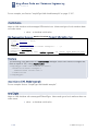
An index is represented as an operation with the <<index>> stereotype and parameter
list. The operation name is equal to the index name and the parameter list of the
operation is a column names for the index. The uniqueness of the index is ignored (not
mapped).
DDL script for an index example that creates the Person table and two indexes:
CREATE TABLE Person (
id INTEGER NOT NULL PRIMARY KEY,
socialId NUMBER(10) NOT NULL UNIQUE,
lastName VARCHAR(20) NOT NULL,
firstName VARCHAR(10) NOT NULL,
sex CHAR(1)
);
CREATE UNIQUE INDEX bySocialId ON Person(socialId);
CREATE INDEX byName ON Person(lastName,firstName);
Representation using UML concepts:
<<table>>
Person
-firstName[1] : VARCHAR ( 10 )
-lastName[1] : VARCHAR ( 20 )
-sex : char ( 1 )
<<PK>>
-id[1] : INTEGER
<<unique>>
-socialId[1] : NUMBER ( 10 )
<<index>>
+byName( lastName, firstName )
+bySocialId( socialId )
Figure 32 -- Index example
Trigger
A trigger is an activity executed by the DBMS as a side effect or instead of a modification
of a table or view to ensure consistent system behavior on data operations.
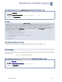
A Trigger is represented as an operation with the <<trigger>> stereotype.
DDL script for trigger example that creates trigger:
CREATE TRIGGER logActions BEFORE INSERT OR DELETE OR UPDATE
ON Person
<triggered SQL statement>;
Representation using UML concepts:
© 2005 No Magic, Inc.
2-47
2
MagicDraw Code Engineering
Database Engineering
<<table>>
Person
...
<<trigger>>
+logActions()
...
Figure 33 -- Trigger example
View
A View is a construct for creating a virtual table based on one or more existing tables or
views.
A class with the <<view>> stereotype represents a view in a schema of a database.
The View column is modeled as an attribute. Relationships between the View and its
underlying tables ("FROM" clause) are modeled as dependencies with <<reference>>
stereotype. Referenced table alias is modeled as the name of the dependency,
referenced column list as the "columns" tagged value on the dependency
2-48
View element
UML concept
Script example
View
Class with the <<view>>
stereotype
CREATE VIEW
View name
Class name
Column
Attribute
Column name
Attribute name
Derived column
Attribute
– <expression> AS
<name>
default value <expression>, Account.balance AS
name <name>
total
–*
Attribute name
*
–<tablename>.*
Attribute name
P.*
–<columnname>
Attribute name
Balance
–
<tablename>.<columnna
me>
Attribute name
<columnname> and
default value
<tablename>.<columnna
me>
Account.balance
–<expression>
Generated unique attribute
name and default value
<expression>
Table reference
Dependency
© 2005 No Magic, Inc.
MagicDraw Code Engineering
Database Engineering
View element
UML concept
Script example
Referenced table alias
Dependency name
P
Referenced column list
"columns" tagged value on
the dependency
Id,firstName,lastName
2
DDL script for view example:
CREATE TABLE Person (
id INTEGER NOT NULL,
socialId NUMBER(10) NOT NULL,
lastName VARCHAR(20) NOT NULL,
firstName VARCHAR(10) NOT NULL,
sex CHAR(1)
);
CREATE TABLE Account (
accountNo INTEGER NOT NULL,
balance FLOAT(5) DEFAULT 0.0 NOT NULL,
personalId INTEGER NOT NULL
);
CREATE VIEW ImportantClient
AS SELECT P.*, Account.balance as total
FROM Person as P(id,firstName,lastName), Account
WHERE balance >= 1000000.00 AND personId = P.id;
Representation using UML concepts:
Figure 34 -- View example
DDL DIALECTS
This section reviews DDL implementations from different vendors. Specific
implementation usually states compliance to some level of SQL standard and provides
some extensions.
© 2005 No Magic, Inc.
2-49
2
MagicDraw Code Engineering
Database Engineering
Standard SQL2
For SQL2 statements supported by MagicDraw UML see Section Supported SQL
statements, “Supported SQL statements”, on page 55.
MagicDraw UML schema package is located within a database package. Database
definition statement is not the part of the SQL2 standard - it is an analogue of a
Database (a Catalog).
NOTE A Catalog has no explicit definition statement. If a database package for a
Catalog does not exist, it should be created (when it is referred for the first time).
Cloudscape
Informix Cloudscape v3.5 dialect has no database definitions statement. A database
package with the name specified by CurrentDatabaseName property is used.
This dialect has CREATE INDEX and CREATE TRIGGER statements that are not the part
of a SQL2 standard but that should be taken into account while reversing DDL script of
this dialect.
This dialect has some syntax differences from SQL2 standard because of extensions (e.g.
some schema definition statements can have PROPERTIES clause). These extensions are
ignored while reversing.
Oracle Oracle8
Oracle Oracle8 dialect has CREATE DATABASE, CREATE INDEX, and CREATE
TRIGGER statements that are not the part of SQL2 standard but that should be taken
into account while reversing DDL script of this dialect.
This dialect has some syntax differences from SQL2 standard because of extensions (e.g.
some schema definition statements can have STORAGE clause). These extensions are
ignored while reversing.
Oracle Oracle8 has object oriented DDL statements (CREATE TYPE and CREATE TYPE
BODY). Additional object oriented Oracle8 schema objects are Object Types, Nested
Object Types, Nested Table, VARRAY, Object Tables, and Object Views.
2-50
© 2005 No Magic, Inc.
MagicDraw Code Engineering
Database Engineering
2
STEREOTYPES FOR MAGICDRAW
CONSTRUCTS
The following table lists stereotypes that are used with MagicDraw UML constructs to
represent a database structure:
Model Item
Stereotype
Description
Default item stereotype for
forward engineering
Package
<<database>
>
See Section “Database”
on page 2 -39
If
EnableDefaultStereotypes
property is true,
<<database>>
stereotype is used for first
level packages, and
<<schema>> stereotype
is used for second level
packages;
Otherwise none.
<<schema>> See Section “Schema” on
page 2 -40
Class
Attribute
Operation
Dependency
© 2005 No Magic, Inc.
<<table>>
See Section “Table” on
page 2 -40
<<view>>
See Section “View” on
page 2 -48
<<PK>>
See Section “Primary Key”
on page 2 -43
<<unique>>
See Section “Uniqueness”
on page 2 -43
<<PK>>
See Section “Primary Key”
on page 2 -43
<<unique>>
See Section “Operations”
on page 2 -33
<<check>>
See Section “Check” on
page 2 -45
<<index>>
See Section “Index” on
page 2 -46
<<trigger>>
See Section “Trigger” on
page 2 -47
<FK>>
See Section “Relationship
cardinalities” on
page 2 -35
<<reference>
>
See Section “Relationship
cardinalities” on
page 2 -35
If
EnableDefaultStereotypes
property is true,
<<table>> stereotype is
used;
Otherwise none.
None
None
2-51
2
MagicDraw Code Engineering
Database Engineering
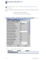
PROPERTIES OF CODE ENGINEERING SET
FOR DDL
There are two separate properties sets, stored as properties of code engineering set for
DDL:
•
Properties for DDL script generation,
•
Properties for DDL script reverse engineering.
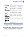
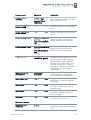
Properties for DDL script reverse engineering and generation
Figure 35 -- CG Properties Editor dialog box. DDL properties
Property name
Values list
Description
Reverse engineering features
2-52
© 2005 No Magic, Inc.
MagicDraw Code Engineering
Database Engineering
2
Property name
Values list
Description
Column default
nullability
Dialect default
(default), not
specified, NULL,
NOT NULL
If column has no NULL or NOT
NULL constraint specified, the value
of this property is used.
Create catalog sets
current catalog
True (default), false
Specifies whether create catalog
statement changes current catalog
name.
Create schema sets
current schema
True (default), false
Specifies whether create schema
statement changes current schema
name.
Default catalog name
DefaultCatalogNone Specifies current database name.
(default),
Used when DDL script does not
DefaultCatalogPack specify database name explicitly.
age, any entered by
the user
Default schema name
DefaultSchemaNone Specifies current schema name.
(default),
Used when DDL script does not
DefaultSchemaPack specify schema name explicitly.
age, any entered by
the user
Drop statements
Deferred (default),
Immediate, Ignored
Map Null/not Null
constraints to
Stereotypes (default), When parsing DDLs, the null/not
Multiplicity
null constraints are modeled as
either stereotypes or multiplicity.
Map foreign keys
True (default), false
A dependency with <<FK>>
stereotype is created, to represent
Foreign Key.
Map indexes
True (default), false
An operation with <<index>>
stereotype is added into class, to
represent index.
Map triggers
True (default), false
An operation with <<trigger>>
stereotype is added into class to
represent trigger.
Map views
True (default), false
A class with <<view>> stereotype
is created to represent view.
0, 0..1, any entered
by user
If the attribute multiplicity is not
specified, the value of this property is
used.
Specifies whether execution of drop
statements may be deferred, or must
be executed, or must be ignored.
Deferred drop may be enabled if
elements are recreated later. This
will save existing views. Attribute
stereotypes, multiplicity and default
value always are not dropped
immediately.
Generation features
Default attribute
multiplicity
© 2005 No Magic, Inc.
2-53
2
MagicDraw Code Engineering
Database Engineering
Generate Null constraint
2-54
True, false (default)
If true, generates NULL constraint for
column attribute with [0..1]
multiplicity. If DBMS, you use,
support NULL, you can enable this to
generate NULL constrains.
See also:
GenerateNotNullConstraint,
AttributeDefaultMultiplicity
Generate extended index True, false (default)
name
If true, generates index name of the
form: TableName_IndexName.
Generate extended
trigger name
True, false (default)
If true, generates trigger name of the
form: TableName_TriggerName.
Generate index for
primary key
True (default), false
If the DBMS, you use, requires
explicit indexes for primary key, you
may enable explicit index creation
using this flag.
See also: GenerateIndexForUnique
Generate index for
unique
True (default), false
If the DBMS, you use, requires
explicit indexes for primary key or
unique columns, may enable explicit
index creation using this flag. See
also: GenerateIndexForPK
Generate not Null
constraint
True (default), false
If true, generates NOT NULL
constraint for column attribute with
[1] multiplicity. If you set
GenerateNullConstraint, you may
wish to do not generate NOT NULL
constrain.
See also: GenerateNullConstraint,
AttributeDefaultMultiplicity
Generate qualified
names
True (default), false
If value of Generate Qualified
Names check box is true, package
name is generated before the table
or view name.
For example: <<database>>
package MQOnline includes
<<table>> class libraries. Then
check box Generate Qualified
Names is selected as true in
generated source would be written:
DROP TABLE MQOnline.libraries;
Then check box Generate Qualified
Names is selected as false, in
generated source would be written:
DROP TABLE libraries;
Generate quoted
identifiers
True, false (default)
Specifies whether DDL code
generator should generate quoted
names of identifiers.
© 2005 No Magic, Inc.
MagicDraw Code Engineering
Database Engineering
Object creation mode
2
The Object Creation Mode combo box has the following
options:
only CREATE statements
DROP & CREATE statements
CREATE OR REPLACE statements (only for Oracle dialect;
default for this dialect)
DROP IF EXISTS & CREATE statements (only for MySQL
dialect; default for this dialect).
SUPPORTED SQL STATEMENTS
This section lists SQL statements that MagicDraw UML supports (that are parsed and
mapped into UML constructs).
The following table provides SQL2 SQL schema statements that are supported and that
are NOT supported in MagicDrawTM UML:
SQL schema statement
Supported
(Yes/No)
SQL schema definition
statement
Schema definition
Yes
Table definition
Yes
View definition
Yes
Alter table statement
Yes
Grant statement
No
Domain definition
No
Assertion definition
No
Character set definition
No
Collation definition
No
Translation definition
No
Drop table statement
Yes
Drop view statement
Yes
Revoke statement
No
Alter domain statement
No
Drop assertion statement
No
Drop domain statement
No
SQL schema manipulation
statement
Drop character set statement No
Drop collation statement
No
Drop translation statement
No
Some SQL schema statements (e.g. schema definition, table definition) allow implicit
catalog name and unqualified schema name. In addition to SQL schema statements, the
following SQL session statements must be supported:
© 2005 No Magic, Inc.
2-55
2
MagicDraw Code Engineering
Database Engineering
•
Set catalog statement - sets the current default catalog name.
•
Set schema statement - sets the current default unqualified
schema name.
MagicDraw supports the following widely used by dialects statements that are not the
part of SQL2:
•
Database definition statement (CREATE DATABASE) that creates
database
•
Index statements (CREATE INDEX, DROP INDEX) that create an
index on table and remove it
•
Trigger statements (CREATE TRIGGER, DROP TRIGGER) that
create a trigger on table and remove it.
The following table provides details on mapping on the supported SQL schema
manipulation statements into MagicDraw constructs:
2-56
© 2005 No Magic, Inc.
MagicDraw Code Engineering
Database Engineering
DDL Statement or
Concept
Action, model
Item
Description
Visible
Alter table statement
Modify class
Elements: table name and alter
table action. Alter table action –
one of: add column, add table
constraint, alter column, drop
table constraint, drop column.
Yes
Add column definition
Define attribute Elements: column definition.
Yes
Add table constraint
definition
Define method
Yes
Alter column definition
Modify attribute Elements: mandatory column
name, default clause (for add
default statement only).
Yes
Drop table constraint
definition
Delete method
Yes
Elements: table constraint
definition.
Elements: constraint name, drop
behavior
Drop column definition Delete attribute Elements: column name, drop
behavior
Yes
Drop schema statement Delete package Elements: schema name, drop
behavior
Yes
Drop table statement
Delete class
Elements: table name, drop
behavior
Yes
Drop view statement
Delete class
Elements: table name, drop
behavior
Yes
Drop behavior
Action property
Modifiers: CASCADE, RESTRICT
No
2
TIPS
Short representation for primary key constraint
When primary key is made out of several columns, and columns order is not important,
short primary key representation may be used. Columns that make up the primary key
must be marked with <<PK>> stereotype. Because a table can contain only one (if
any) primary key, these columns are concatenated into one primary key.
Short primary key representation using UML concepts and generated DDL script:
© 2005 No Magic, Inc.
2-57
2
MagicDraw Code Engineering
Database Engineering
CREATE TABLE ShortPKExample (
col1 INTEGER,
col2 INTEGER,
PRIMARY KEY (col1, col2)
);
If the order of columns within the primary key is important, constraint representation as
an operation with parameters must be used:
CREATE TABLE NoShortPKExample (
col1 INTEGER,
col2 INTEGER,
PRIMARY KEY (col2, col1)
);
Primary key constraint with overhead info
Consider such primary key definition using UML concepts and generated DDL script:
<<table>>
PKWithOverheadExample
-col2 : INTEGER
<<unique>>
-col1 : INTEGER
<<PK>>
+pk( col1, col2 )
CREATE TABLE PKWithOverheadExample (
col1 INTEGER UNIQUE,
col2 INTEGER,
PRIMARY KEY (col1, col2)
2-58
© 2005 No Magic, Inc.
MagicDraw Code Engineering
Database Engineering
2
);
This representation is valid, but the primary key contains overhead info (specifically
column col2). Unique column alone may be used as a valid primary key:
<<table>>
PKWithoutOverheadExample
-col2 : INTEGER
<<PK>>
-col1 : INTEGER
CREATE TABLE PKWithoutOverheadExample (
col1 INTEGER PRIMARY KEY,
col2 INTEGER
);
© 2005 No Magic, Inc.
2-59
CORBA IDL MAPPING TO UML
3
CORBA IDL mapping to UML is based on UMLTM Profile for CORBATM Specification, Version
1.0, April 2002. http://www.omg.org/technology/documents/formal/profile_corba.htm.
Differences between UML Profile for CORBA specification and mapping in MagicDraw is listed
below. Most differences are present because MagicDraw does not fully support UML 1.4.
•
CORBA IDL exception is mapped to Core::Class, instead of
CommonBehavior::Exception. MagicDraw does not support
CommonBehavior::Exception.
•
Constraints defined in UML Profile for CORBA specification are not
checked in MagicDraw.
•
For storing constants, UML class instead of UtilityClass is used.
•
Use simplified “1” multiplicity instead of “1...1”.
•
Stereotype CORBAAnonymousFixed is introduced. It is used to represent
anonymous fixed types. Fixed types without names are mapped to inner
classes with stereotype CORBAAnonymousFixed. These classes are
binded with CORBA::fixed classes.IDL Code:
struct baz
{
fixed <8, 4> high_scale;
fixed <8, 2> low_scale;
};
This code is mapped to the following diagram:
© 2005 No Magic, Inc.
3-60
MagicDraw Code Engineering
CORBA IDL Mapping to UML
3
<<CORBAStruct>>
baz
+high_scale : fixed_8_4
+low_scale : fixed_8_2
<<CORBAAnonymousFixed>>
fixed_8_2
<<CORBAAnonymousFixed>>
fixed_8_4
<<binding>>
<8, 4>
<<binding>>
<8, 2>
digits : short
scale : short
fixed
MagicDraw presents a CORBA IDL diagram, which simplifies the creation of standard CORB IDL
elements. The loffowing elements are available in the CORBA IDL diagram:
Button
Shortcut key
M
CORBA IDL Module
I
CORBA IDL Interface
V
CORBA IDL Value
SHIFT+P
3-61
Model Element
Class by Pattern
© 2005 No Magic, Inc.
MagicDraw Code Engineering
CORBA IDL Mapping to UML
Button
Shortcut key
G
3
Model Element
Generalization
Truncatable
Generalization
Value Support
Generalization
CORBA IDL Association
© 2005 No Magic, Inc.
S
Association
A
Aggregation
F
Composition
P
Package
C
Class
I
Interface
D
Dependency
3-62
3
MagicDraw Code Engineering
CORBA IDL Mapping to UML
Button
Shortcut key
B
SHIFT+C
W
3-63
Model Element
Binding Dependency
Containment
Separator
© 2005 No Magic, Inc.
4
EJB 2.0 - UML
In MagicDraw, EJB-UML mapping is based on UML Profiles for EJB. The UML Profiles for EJB is
a mapping from Unified Modeling Language (UML) to the Enterprise JavaBeans (EJB)
architecture. The mapping specifies the standard representation for elements of the EJB
architecture in UML models.
UML Profiles for EJB consist of Java, EJB Design, and EJB Deployment profiles. The Java Profile
defines the subset of Java constructs that are needed to support the EJB Profiles. EJB Design
Profile defines how to model EJB applications using the interfaces and the implementation
classes of an enterprise bean. The EJB Deployment Profile defines mapping of EJB components
contained in EJB-JAR archives and deployment on Application Servers to UML.
Java Profile
This section describes stereotypes and tagged values introduced in the Java Profile.
STEREOTYPES
Stereotype
Applies To
Definition
«JAR»
Artifact,
Component
Specializes the standard UML Stereotype «file». Indicates
that the Artifact or Component represents a JAR.
«JARInclude»
Dependency
Indicates that the supplier of the Dependency, a JAR ,
Java .class file, or other file, is included “by value” (i.e.,
copied into) the JAR that is the client of the Dependency
«JARReference»
Usage
Indicates that the supplier is a model element that is not
contained in the archive but is referenced by it in the
META-INF/MANIFEST.MF file
«JavaSourceFile»
«file»
Specializes the standard UML Stereotype «file». Indicates
that the Artifact describes a Java Source File.
NOTE
The compiled “*.class” file is not modeled
by this profile.
TAGGED VALUES
Tagged Values of the Java Profile are included in current implementation of MagicDraw but are
not used in EJB 2.0 code engineering.
Tagged Value
Applies To
Definition
JavaStrictfp
Class
A Boolean value indicating whether or not the Java
Class is FP-strict
© 2005 No Magic, Inc.
4-67
4
MagicDraw Code Engineering
EJB 2.0 - UML
JavaStatic
Class
A Boolean value indicating whether or not the Java
Class is static.
JavaVolatile
Attribute or
A Boolean value indicating whether or not the Java
AssociationEnd Field is volatile.
JavaDimensions
Attribute,
An Integer indicating the number of array dimensions
AssociationEnd declared by the Java Field or Parameter.
or Parameter
JavaCollection
Attribute or
A String containing the name of the Java Collection
AssociationEnd Type used to implement an Attribute or Association End
with complex multiplicity.
JavaNative
Operation or
Method
A Boolean value indicating whether or not the
Operation or Method is native.
JavaThrows
Operation or
Method
A comma-delimited list of names of Java Exception
Classes.
JavaFinal
Parameter
A Boolean value indicating whether or not the
Parameter is final.
EJB Design Profile
This section describes stereotypes and tagged values introduced in the EJB Design Profile.
STEREOTYPES
Stereotype
Applies To
«EJBBusiness»
Operation
Definition
Indicates that the Operation represents an
instance-level business method, a method that
supports the “business logic” of the EJB. Contrast
with class-level business methods on home
interfaces, which are stereotyped «EJBHome»
«EJBCmpField»
Attribute,
Indicates that the Attribute or Association End
AssociationEnd represents a container-managed field for an EJB
Entity Bean with container-managed persistence
«EJBCmrMethod»
Dependency
A UML Dependency with the
«EJBRelationshipRole» Association End as the
client and the abstract get/set Methods of the
relationship as the suppliers. This connects the
EJB Relationship to the pair of container
managed relationship methods, and allows the
decoupling of the role name to the name of the
CMR fields. (EJB 2.0 only)
«EJBCreate»
Operation
Indicates that the Operation represents an EJB
Create Method.
4-68
© 2005 No Magic, Inc.
MagicDraw Code Engineering
EJB 2.0 - UML
4
«EJBEnterpriseBean»
Class
Specializes the standard UML Stereotype
«implementationClass». An abstract Class that
represents an EJB Enterprise Bean. The
stereotype is applied to the implementation class
for the EJB.
«EJBEntityBean»
Class
Indicates that the Class represents an EJB Entity
Bean. Specializes «EJBEnterpriseBean».
«EJBFinder»
Operation
Indicates that the Operation represents an EJB
Finder Method.
«EJBHome»
Operation
Indicates that the Operation represents an EJB
Home Method, either local or remote, which is a
class-level “business” method, as opposed to a
“create”, “finder”, etc. method. Contrast with
«EJBBusiness».
«EJBLocalMethod»
Operation
Indicates that the Operation represents a method
that is exposed on either the local or local-home
interface. The former case is assumed if the EJB
Business stereotype is also present. (EJB 2.0 only)
«EJBLocalReference»
Dependency
A stereotyped Dependency representing an EJB
Local Reference, where the client is an EJB-JAR
and the supplier is an EJB Enterprise Bean. (EJB
2.0 only)
«EJBMessageDrivenBean»
Class
Indicates that the Class represents an EJB
Message Driven Bean. Specializes
«EJBEnterpriseBean». (EJB 2.0 only)
«EJBPrimaryKey»
Usage
Indicates that the supplier of the Usage
represents the EJB Primary Key Class for the EJB
Enterprise Bean represented by the client.
«EJBPrimaryKeyField»
Attribute.
Specializes «EJBCmpField». Indicates that the
AssociationEnd Attribute or Association End is the primary key
field for an EJB Entity Bean with containermanaged persistence.
«EJBRealizeHome»
Abstraction
Indicates that the supplier of the Abstraction
represents an EJB Remote Home Interface for the
EJB Enterprise Bean Class represented by the
client.
«EJBRealizeLocal»
Abstraction
Indicates that the supplier of the Abstraction
represents an EJB Local Interface for the EJB
Enterprise Bean Class represented by the client.
(EJB 2.0 only)
«EJBRealizeLocalHome»
Abstraction
Indicates that the supplier of the Abstraction
represents an EJB Local Home Interface for the
EJB Enterprise Bean Class represented by the
client. (EJB 2.0 only)
«EJBRealizeRemote»
Abstraction
Indicates that the supplier of the Abstraction
represents an EJB Remote Interface for the EJB
Enterprise Bean Class represented by the client.
© 2005 No Magic, Inc.
4-69
4
MagicDraw Code Engineering
EJB 2.0 - UML
«EJBReference»
Dependency
A stereotyped Dependency representing an EJB
(Remote) Reference, where the client is an EJBJAR and the supplier is an EJB Enterprise Bean.
«EJBRelationship»
Association
Indicates that the EJB Entity Bean at the supplier
Association End represents a container-managed
relationship field for the client EJB Entity Bean.
(EJB 2.0)
«EJBRelationshipRole»
AssociationEnd Indicates the Association End of an
«EJBRelationship».
«EJBRemoteMethod»
Operation
Indicates that the Operation represents a method
that is exposed on either the remote or remotehome interface. The former case is assumed if
the EJB Business stereotype is also present.
«EJBRoleNameRef»
Actor
The name of security role reference used
programmatically in a bean’s source code and
mapped to an EJB Role Name in the Deployment
Model.
«EJBRoleLink»
Dependency
Indicates a Dependency between a client EJB
Role Name Reference (Design Model) and a
supplier EJB Role Name (Deployment Model).
«EJBSessionBean»
Class
Indicates that the Class represents an EJB
Session Bean. Specializes «EJBEnterpriseBean».
«EJBSelect»
Operation
An Operation that is a select method in an EJB
Entity Bean. (EJB 2.0 only)
«EJBSecurityRoleRef»
Association
Indicates a Dependency between an EJB client,
and an EJB Role Name Reference supplier.
TAGGED VALUES
Tagged Value
Applies To
Definition
EJBAbstractSchemaName
Class «EJBEntityBean»
A String representing the
abstract name used for a
schema associated with a CMP
2.0 entity bean.
EJBAcknowledgeMode
Class
«EJBMessageDrivenBean»
An enumeration with values
Auto Acknowledge or Dups OK
Acknowledge indicating the type
of message acknowledgment
used for the onMessage
message of a message-driven
bean that uses bean-managed
transaction demarcation.
EJBComponentInterface
Dependency
«EJBReference» or
«EJBLocalReference»
The name of the EJB Enterprise
Bean’s “Component” Interface
(local or remote).
4-70
© 2005 No Magic, Inc.
MagicDraw Code Engineering
EJB 2.0 - UML
4
EJBCmpVersion
Class «EJBEntityBean»
An enumeration with values 1.x
or 2.x. Indicates the type of
CMP used by the EJB Entity
Bean
EJBCmrFieldType
AssociationEnd
«EJBRelationshipRole»
Type expression property of the
supplier UML Association End
«EJBRelationshipRole».
EJBDisplayName
Class «EJBEnterpriseBean»
A String with the name for the
EJB to be displayed by tools
EJBEnvEntries
Class «EJBEnterpriseBean»
A string of XML tags,
designating the environment
entries used by the EJB
Enterprise Bean.
EJBHomeInterface
Dependency
«EJBReference» or
«EJBLocalReference»
The name of the EJB Enterprise
Bean’s Home Interface (local or
remote).
EJBLink
Dependency
«EJBReference» or
«EJBLocalReference»
The name of the referenced EJB
Enterprise Bean, if it is in the
same Archive or another archive
in the same J2EE Application
Unit, or a path to the bean.
EJBMessageDrivenDestination
Class
«EJBMessageDrivenBean»
An XML tag, designating the
type of destination and the
durability used by the EJB
Message Driven Bean.
EJBMessageSelector
Class
«EJBMessageDrivenBean»
A String specifying the JMS
message selector to be used in
determining which messages a
message-driven bean is to
receive.
EJBNameInJAR
Class «EJBEnterpriseBean»
The name used for the EJB
Enterprise Bean in the EJB-JAR.
Defaults to the name of the EJB
Remote Interface.
EJBPersistenceType
Class «EJBEntityBean»
An enumeration with values
Bean or Container. Indicates
whether the persistence of the
EJB Entity Bean is managed by
the EJB Entity Bean or by its
container, respectively.
EJBQueryString
Operation «EJBFinder» or
«EJBSelect»
The EJB QL statement
corresponding to the method. It
is ignored for BMP Entity Beans
EJBReentrant
Class «EJBEntityBean»
A Boolean value indicating
whether or not the EJB Entity
Bean can be called re-entrantly.
© 2005 No Magic, Inc.
4-71
4
MagicDraw Code Engineering
EJB 2.0 - UML
EJBRefName
Dependency
«EJBReference» or
«EJBLocalReference»
The name of the EJB Enterprise
Bean referenced.
EJBRefType
Dependency
«EJBReference» or
«EJBLocalReference»
The type of referenced EJB
Enterprise Bean, one of the
strings Entity or Session.
EJBRelationshipRoleDescription
AssociationEnd
«EJBRelationshipRole»
A String specifying a description
an EJB relationship role.
EJBRelationshipRoleName
AssociationEnd
«EJBRelationshipRole»
The name of an EJB relationship
role.
EJBResources
Class «EJBEnterpriseBean»
A string of XML tags designating
the resource factories used by
the EJB Enterprise Bean.
EJBResourcesEnv
Class «EJBEnterpriseBean»
A string of XML tags designating
the environment entries used by
the EJB Enterprise Bean.
EJBResultTypeMapping
Operation «EJBFinder» or
«EJBSelect»
The allowed values are the
literal strings Local or Remote. If
the optional corresponding
<result-type-mapping> tag is
not to be used in the
deployment descriptor, then the
value is empty.
EJBSessionType
«EJBSessionBean»
Stateful or Stateless. Indicates
whether or not the EJB Session
Bean maintains state.
EJBTransType
Class «EJBSessionBean» or
Class
«EJBMessageDrivenBean»
An enumeration with values
Bean or Container. Indicates
whether the transactions of the
EJB Session Bean or EJB
Message Driven Bean are
managed by the bean or by its
container, respectively.
EJBVersion
Class «EJBEnterpriseBean»
An enumeration with values 1.1
or 2.0. Indicates the EJB version
of the EJB Enterprise Bean
EJB Deployment Profile
STEREOTYPES
Stereotype
Applies To
Definition
«EJB-JAR»
Artifact,
Component
Specializes the Stereotype «JAR». Indicates
that the Artifact represents an EJB JAR.
4-72
© 2005 No Magic, Inc.
MagicDraw Code Engineering
EJB 2.0 - UML
4
«EJBClientJAR»
Usage
Indicates that the client of the Usage
represents an ejb-client-jar for the EJB-JAR
represented by the supplier of the Usage.
«EJBContainerTransaction»
Actor
Indicates the type of transaction used for
associated Methods. It is combined with a
transaction type stereotype, such as
«EJBRequired». (See the following Table.)
Container transactions are specified using
one or more dependencies, stereotyped
«EJBMethod», from an EJB Enterprise Bean
client to an EJB Container Transaction
Actor supplier
«EJBEnterpriseBeanDeployment»
Component
Indicates that the Component represents
an EJB Enterprise Bean. It resides in an
EJB-JAR. It has tagged values for
overriding default settings in the
corresponding EJB Enterprise Bean Class.
For example, these tagged values can be
used to create a new EJB by specifying
different EJB Home and EJB Remote
interfaces for a shared EJB Enterprise Bean
Class.
«EJBEntityBeanDeployment»
Component
Specializes the standard Stereotype
«EJBEnterpriseBean». Indicates that the
Component represents an EJB Entity Bean.
«EJBExcludeList»
Actor
Indicates an Actor that represents an
Exclude List. An exclude list is specified
using one or more dependencies,
stereotyped «EJBMethod», from an EJB
Enterprise Bean client to an EJB Exclude
List Actor supplier
«EJBMessageDrivenBeanDeployment»
Component
Specializes the standard Stereotype
«EJBEnterpriseBean». Indicates that the
Component represents an EJB Message
Driven Bean.
«EJBMethod»
Dependency Indicates a Dependency between an EJB
Component client and an EJB Method
Permission (or EJB Container Transaction
or EJBExcludeList) supplier that completes
a Method Permission (or Container
Transaction or Exclude List) specification. It
contains a method specification, either
“style 1, 2, or 3”, according to the EJB 2.0
specification.
© 2005 No Magic, Inc.
4-73
4
MagicDraw Code Engineering
EJB 2.0 - UML
«EJBMethodPermission»
Actor
Indicates an Actor that represents a
Method Permission. It contains a tag value
indicating whether or not the method is
“unchecked”. One or more method
permissions are specified using one or
more dependencies, stereotyped
«EJBMethod», from an EJB Enterprise Bean
to an EJB Method Permission Actor
«EJBOverrideHome»
«reside»
Indicates a relationship that, for the client
EJB Enterprise Bean Component, the
supplier UML Interface overrides the Home
Interface that is defined by the EJB
Enterprise Bean. This is a technique for
constructing new EJBs while reusing EJB
Enterprise Bean Classes.
«EJBOverrideLocal»
«reside»
Indicates a relationship that, for the client
EJB Enterprise Bean Component, the
supplier UML Interface overrides the Local
Interface that is defined by the EJB
Enterprise Bean. This is a technique for
constructing new EJBs while reusing EJB
Enterprise Bean Classes.
«EJBOverrideLocalHome»
«reside»
Indicates a relationship that, for the client
EJB Enterprise Bean Component, the
supplier UML Interface overrides the Local
Home Interface that is defined by the EJB
Enterprise Bean. This is a technique for
constructing new EJBs while reusing EJB
Enterprise Bean Classes.
«EJBOverridePrimaryKey»
«reside»
Indicates a relationship that, for the client
EJB Enterprise Bean Component, the
supplier Java Class overrides the EJB
Primary Key Class that is defined by the EJB
Enterprise Bean. This is a technique for
constructing new EJBs while reusing EJB
Enterprise Bean Classes.
«EJBOverrideRemote»
«reside»
Indicates a relationship that, for the client
EJB Enterprise Bean Component, the
supplier UML Interface overrides the
Remote Interface that is defined by the EJB
Enterprise Bean. This is a technique for
constructing new EJBs while reusing EJB
Enterprise Bean Classes.
«EJBRoleName»
Actor
Indicates the name of a security role used
in the definitions of Method Permissions,
etc.
4-74
© 2005 No Magic, Inc.
MagicDraw Code Engineering
EJB 2.0 - UML
4
«EJBRunAsIdentity»
Dependency Indicates a Dependency between an EJB
Role Name supplier and an EJB
Component client that completes a Run As
specification, which names a role under
which methods of the EJB are to be
executed.
«EJBSecurityRole»
Association
Indicates a Dependency between an EJB
JAR client and an EJB Role Name supplier.
It defines the role as part of the archive.
«EJBSessionBeanDeployment»
Component
Specializes the standard Stereotype
«EJBEnterpriseBeanDeployment». Indicates
that the Component represents an EJB
Session Bean.
The «EJBContainerTransaction» Actor model elements always receive a second stereotype,
which identifies the type of transaction.
Transaction Type
Description
«EJBMandatory»
Transactions are mandatory for this method
«EJBNever»
Transactions are never used for this method
«EJBNotSupported»
Transactions aren’t supported for this method
«EJBRequired»
Transactions are required for this method
«EJBRequiresNew»
A new transaction is required for this method
«EJBSupports»
Transactions are supported for this method
TAGGED VALUES
Tagged Value
Applies To
Definition
EJBDisplayName
Artifact «EJB-JAR»
A String with the name for the Archive to
be displayed by tools
EJBMethodDescriptor
Dependency
«EJBMethod»
A String with the subset of XML required
to specify a complete deployment
descriptor <method> tag for a method
or set of methods, using “Style 1, 2, or
3” syntax, as defined by the EJB 2.0
Specification.
EJBUnchecked
Actor
«EJBMethodPermission»
A Boolean that when “true”, indicates
that permission to invoke the specified
methods should not be checked before
invocation. Default is “false”
EJBUseCallerIdentity
Component
«EJBEnterpriseBean»
A Boolean indicating whether or not to
use the caller’s identity when invoking
the bean methods.
© 2005 No Magic, Inc.
4-75
4
MagicDraw Code Engineering
EJB 2.0 - UML
U SING M AGIC D RAW EJB 2.0
Reverse engineering
1
Create EJB 2.0 code engineering set.
NOTE
If the project does not contain profiles required for EJB code
engineering, you will be asked whether you would like to import
the EJB 2.0 template. It is recommended to select Yes.
2
Add java files and EJB deployment descriptor file that are part of concrete
EJB. EJB deployment descriptor file ejb-jar.xml must be in META-INF
directory.
3
Reverse those files.
After the reverse, you will get the following result:
Model elements representing the code will be created. Stereotypes and tagged values
representing EJB tags will be applied to appropriate model elements.
Code generation
We will create a simple example and we will go step by step from the beginning to the generated
code. As an example we will take a reservation system for a theater ticket reservation. It will
consist of single session enterprise bean ReservationBean. You may find this example in the
<MagicDraw installation directory>, examples folder.
4-76
1
Create a new MagicDraw project from EJB 2.0 template.
2
Create a new class diagram.
3
Create an interface Reservation that extends javax::ejb:EJBObject
interface in the class diagram.
4
Create operation bookSeats (playName : java::lang::String, userName :
java::lang::String, quantity : java::lang::String) in the bean’s class. The
operation should throw java::rmi::RemoteException.
To specify which exceptions the method throws, open the Operation
Specification dialog box, click the Language Properties button and in the
CG Properties Editor dialog box, Java tab specify the Throws Exceptions
property (java.rmi.RemoteException).
5
Create a class with name ReservationBean. The class will be an enterprise
session bean.
6
Make the class realizes SessionBean interface from javax.ejb package.
7
Open the ReservationBean’s specification and add EJBSessionBean
stereotype to the class and EJBNameInJAR tagged value - ReservationEJB.
© 2005 No Magic, Inc.
MagicDraw Code Engineering
EJB 2.0 - UML
4
8
Create operation bookSeats( playName : java::lang::String, userName :
java::lang::String, quantity : java::lang::String ) in the bean’s class. You
can copy the operation from the Reservation interface (select the operation
in the Reservation interface press Ctrl button and drag the operation to
bean’s class.
9
Create an interface ReservationHome that extends javax::ejb::EJBHome
interface and has operation public Reservation create() throws
CreateException, RemoteException.
10
Create abstraction links from the bean’s class to the Reservation and
Reservation Home interfaces. On the abstraction between
ReservationBean and Reservation add stereotype EJBRealizeHome. On the
abstraction between ReservationBean and ReservationHome interface add
stereotype EJBRealizeRemote.
11
Create a new EJB 2.0 code engineering set.
12
In the containment tree select ReservationBean, Reservation and
ReservationHome and drag them to the set.
13
In the ComponentView select ReservationBean.java component, open
specification for it and add stereotype EJBSessionBeanDeployment.
14
In the Component View package create new component ejb-jar.jar. Open
specification and add stereotype EJB-JAR to it.
15
Create a new Implementation Diagram.
16
Drag ReservationBean.java and ejb-jar.jar components to the diagram.
17
Create dependency link from the ReservationBean.java component to ejbjar.jar component and add stereotype implement to the dependency.
18
Drag ejb-jar.jar component from the in the Containment Tree from
Component View to the EJB 2.0 code engineering set.
19
Generate the code.
© 2005 No Magic, Inc.
4-77
5
XML SCHEMA
Reference: http://www.w3.org/TR/xmlschema-2/
XML
SCHEMA MAPPING TO
UML
ELEMENTS
Defined stereotypes
Stereotype name
XSDcomponent
XSDattribute
© 2005 No Magic, Inc.
Base Stereotype Applies to
Defined TagDefinitions Details
Class
id – string
Attribute
AssociationEnd
Binding
Generalization
Comment
Component
XSDcomponent Attribute
The base and
abstract
stereotype for
all XML
Schema
stereotypes
used in UML
profile
fixed – some fixed
element value
form - (qualified |
unqualified)
refString – string
representation of
reference to other
attribute.
ref – actual reference
to other attribute
use - (optional |
prohibited |
required) : optional
5-77
5
MagicDraw Code and Database Engineering
XML Schema
XSDelement
XSDcomponent Attribute
abstract – (true | false)
AssociationEnd block - (extension |
restriction |
substitution)
final - (extension |
restriction)
fixed – some fixed
element value
form - (qualified |
unqualified)
nillable – (true | false)
refString – string
representation of
reference to other
attribute.
ref – actual reference
to other attribute
substitutionGroup –
actual reference to
UML ModelElement
substitutionGroupStrin
g – string
representation of
substitution group
key_unique_keyRef – a
list of referenced UML
Attributes
sequenceOrder – a
number in sequence
order
XSDcomplexType
XSDcomponent Class
block – (extension |
restriction)
final – (extension |
restriction)
mixed – (true | false)
XSDsimpleContent
Class
simpleContentId –
string
XSDcomplexContent
Class
complexContentId –
string
complexContentMixed
XSDgroup
XSDcomponent Class
XSDgroupRef
XSDcomponent Attribute
sequenceOrder – a
AssociationEnd number in sequence
order
XSDall
5-78
Class
allId – string
maxOccurs
minOccurs
© 2005 No Magic, Inc.
MagicDraw Code and Database Engineering
5
XML Schema
XSDchoice
Class
choiceId – string
maxOccurs
minOccurs
sequenceOrder – a
number in sequence
order
XSDsequence
Class
sequenceId – string
maxOccurs
minOccurs
sequenceOrder – a
number in sequence
order
XSDrestriction
XSDcomponent Generalization
XSDextension
XSDcomponent Generalization
XSDattributeGroup
XSDcomponent Class
XSDsimpleType
XSDcomponent Class
final - (#all | (list |
union | restriction))
XSDlist
XSDcomponent Class
listId - string
XSDunion
XSDcomponent Class
unionId - string
XSDannotation
XSDcomponent Comment
appInfoSource
appInfoContent
source
xml:lang
XSDany
XSDcomponent Attribute
namespace – string
processContents - (lax
| skip | strict);
default strict
sequenceOrder – a
number in sequence
order
XSDanyAttribute
XSDcomponent Attribute
namespace – string
processContents - (lax
| skip | strict);
default strict
XSDschema
XSDcomponent Class
attributeFormDefault
blockDefault
elementFormDefault
finalDefault
targetNamespace –
reference to some
ModelPackage
version
xml:lang
XSDnotation
XSDcomponent Attribute
public
system
XSDredefine
XSDcomponent Class
© 2005 No Magic, Inc.
5-79
5
MagicDraw Code and Database Engineering
XML Schema
XSDimport
XSDcomponent Permision
<<import>>
schemaLocation
XSDinclude
XSDcomponent Component
XSDminExclusive
XSDcomponent Attribute
fixed = boolean : false
XSDminInclusive
XSDcomponent Attribute
fixed = boolean : false
XSDmaxExclusive
XSDcomponent Attribute
fixed = boolean : false
XSDmaxInclusive
XSDcomponent Attribute
fixed = boolean : false
XSDtotalDigits
XSDcomponent Attribute
fixed = boolean : false
XSDfractionDigits
XSDcomponent Attribute
fixed = boolean : false
XSDlength
XSDcomponent Attribute
fixed = boolean : false
XSDminLength
XSDcomponent Attribute
fixed = boolean : false
XSDmaxLength
XSDcomponent Attribute
fixed = boolean : false
XSDwhiteSpace
XSDcomponent Attribute
fixed = boolean : false
value
XSDpattern
XSDcomponent Attribute
XSDenumeration
XSDcomponent Attribute
XSDunique
Attribute
selector
field
XSDkey
Attribute
selector
field
XSDkeyref
Attribute
selector
field
refer – UML Attribute
referString - String
XSDnamespace
ModelPackage
xmlns
Permission
attribute
5-80
•
XML schema attribute maps to UML Attribute with stereotype XSDattribute.
•
default maps to initial UML Attribute or AssociationEnd value.
•
annotation – to UML Attribute or AssociationEnd documentation.
•
name – to UML Attribute or AssociationEnd name.
•
type or content simpleType – to UML Attribute or AssociationEnd type.
© 2005 No Magic, Inc.
MagicDraw Code and Database Engineering
5
XML Schema
Other attributes or elements maps to corresponding tagged values.
<attribute
default = string
fixed = string
form = (qualified | unqualified)
id = ID
name = NCName
ref = QName
type = QName
use = (optional | prohibited | required) : optional
{any attributes with non-schema namespace . . .}>
Content: (annotation?, (simpleType?))
</attribute>
Example
<xs:attribute name="age" type="xs:positiveInteger" use="required"/>
ref value is generated from ref or refString TaggedValue.
One of ref or name must be present, but not both.
If ref is present, then all of <simpleType>, form and type must be absent.
type
and <simpleType> must not both be present.
attribute UML Model example
<xs:schema xmlns:nm = "http://nomagic.com" xmlns:xs =
"http://www.w3.org/2001/XMLSchema" targetNamespace = "http://nomagic.com" >
© 2005 No Magic, Inc.
5-81
5
MagicDraw Code and Database Engineering
XML Schema
<xs:attribute name = "name" type = "xs:string" default = "minde"
fixed = "fixed_value" form = "qualified" use = "optional" >
<xs:annotation >
<xs:documentation >name attribute
documentation</xs:documentation>
</xs:annotation>
</xs:attribute>
<xs:attribute name = "address" fixed = "fixed_value" form =
"qualified" use = "optional" >
<xs:annotation >
<xs:documentation >surname attribute
documentation</xs:documentation>
</xs:annotation>
<xs:simpleType >
<xs:restriction base = "xs:string" />
</xs:simpleType>
</xs:attribute>
<xs:attribute name = "surname" type = "xs:string" />
<xs:attributeGroup name = "attr_group" >
<xs:attribute ref = "nm:name" >
<xs:annotation >
<xs:documentation >reference
documentation</xs:documentation>
</xs:annotation>
</xs:attribute>
<xs:attribute ref = "nm:surname" />
</xs:attributeGroup>
</xs:schema>
element
Maps to UML Attribute or UML AssociationEnd with stereotype XSDelement.
• annotation – to UML Attribute or
UML AssociationEnd documentation.
• default - to initial UML Attribute or
UML AssociationEnd value.
•
maxOccurs - to multiplicity upper range. Value unbounded maps to
asterisk in UML.
•
minOccurs – to multiplicity lower range.
• name – to UML Attribute or
UML AssociationEnd name.
• type or content (simpleType | complexType) – to UML Attribute or
UML
AssociationEnd type.
Other properties maps to corresponding tagged values.
5-82
© 2005 No Magic, Inc.
MagicDraw Code and Database Engineering
5
XML Schema
XML Representation Summary: element Element Information Item
<element
abstract = boolean : false
block = (#all | List of (extension | restriction | substitution))
default = string
final = (#all | List of (extension | restriction))
fixed = string
form = (qualified | unqualified)
id = ID
maxOccurs = (nonNegativeInteger | unbounded)
minOccurs = nonNegativeInteger : 1
name = NCName
nillable = boolean : false
ref = QName
substitutionGroup = QName
type = QName
: 1
{any attributes with non-schema namespace . . .}>
Content: (annotation?, ((simpleType | complexType)?, (unique | key | keyre
</element>
ref value is generated from ref or refString TaggedValue.
One of ref or name must be present, but not both.
If ref is present, then all of <complexType>, <simpleType>, <key>, <keyref>, <unique>,
nillable, default, fixed, form, block and type must be absent, i.e. only minOccurs, maxOccurs, id
are allowed in addition to ref, along with <annotation>.
Example
<xs:element name="PurchaseOrder" type="PurchaseOrderType"/>
<xs:element name="gift">
<xs:complexType>
<xs:sequence>
<xs:element name="birthday" type="xs:date"/>
<xs:element ref="PurchaseOrder"/>
</xs:complexType>
</xs:element>
© 2005 No Magic, Inc.
5-83
5
MagicDraw Code and Database Engineering
XML Schema
element UML Model example
<xs:schema xmlns:nm = "http://nomagic.com" xmlns:xs =
"http://www.w3.org/2001/XMLSchema" targetNamespace = "http://nomagic.com" >
<xs:element name = "name" type = "xs:string" default = "minde" id = "elementID"
abstract = "true" block = "extension" final = "restriction" fixed = "fixedValue" form =
"qualified" nillable = "true" substitutionGroup = "nm:count" >
<xs:annotation >
<xs:documentation >element name documentation</xs:documentation>
</xs:annotation>
</xs:element>
<xs:element name = "count" >
<xs:annotation >
<xs:documentation >element count documenation</xs:documentation>
</xs:annotation>
<xs:simpleType >
<xs:restriction base = "xs:number" />
</xs:simpleType>
</xs:element>
<xs:element name = "hour" type = "xs:integer" />
<xs:element name = "minute" type = "xs:integer" substitutionGroup = "nm:count" />
<xs:element name = "surname" type = "xs:string" minOccurs = "1" maxOccurs =
"unbounded" />
<xs:complexType name = "some_type" >
<xs:all >
<xs:element ref = "nm:hour" minOccurs = "0" maxOccurs = "1" >
<xs:annotation >
<xs:documentation >hour ref
documentatuion</xs:documentation>
</xs:annotation>
</xs:element>
<xs:element ref = "nm:minute" minOccurs = "0" maxOccurs = "1" />
</xs:all>
</xs:complexType>
5-84
© 2005 No Magic, Inc.
MagicDraw Code and Database Engineering
5
XML Schema
</xs:schema>
complexType
Complex type maps to UML Class with stereotype XSDcomplexType.
•
abstract - to UML Class abstract value(true | false).
•
annotation - to UML Class documentation.
•
attribute – to inner UML Class Attribute or UML Association End.
•
attributeGroup – to UML AssociationEnd or UML Attribute with type
XSDattributeGroup.
•
name – to UML Class name.
This class also can have stereotypes XSDsimpleContent, XSDcomplexContent, XSDall,
XSDchoice, XSDsequence.
No stereotype – the same as “XSDsequence”.
Generalization between complex type and other type has stereotype XSDrestriction or
XSDextension. We assume stereotype XSDextension if generalization do not have stereotype.
Some complex mapping:
•
complexType with simpleContent – to UML Class. This class must be
derived from other class and can must have stereotype XSDsimpleContent.
•
complexType with complexContent – to UML Class. This class must be
derived from other class and must have stereotype XSDcomplexContent.
•
complexType with group, all, choice or sequence – to UML class with
appropriate stereotype.
<complexType
abstract = boolean : false
block = (#all | List of (extension | restriction))
final = (#all | List of (extension | restriction))
id = ID
mixed = boolean : false
name = NCName
{any attributes with non-schema namespace . . .}>
Content: (annotation?, (simpleContent | complexContent | ((group | al
((attribute | attributeGroup)*, anyAttribute?))))
</complexType>
© 2005 No Magic, Inc.
5-85
5
MagicDraw Code and Database Engineering
XML Schema
When the <simpleContent> alternative is chosen, the following elements are relevant, and the
remaining property mappings are as below. Note that either <restriction> or <extension> must
be chosen as the content of <simpleContent>.
<simpleContent
id = ID
{any attributes with non-schema namespace . . .}>
Content: (annotation?, (restriction | extension))
</simpleContent>
<restriction
base = QName
id = ID
{any attributes with non-schema namespace . . .}>
Content: (annotation?, (simpleType?, (minExclusive | minInclusive | maxEx
maxInclusive | totalDigits | fractionDigits | length | minLength | maxLengt
whiteSpace | pattern)*)?, ((attribute | attributeGroup)*, anyAttribute?))
</restriction>
<extension
base = QName
id = ID
{any attributes with non-schema namespace . . .}>
Content: (annotation?, ((attribute | attributeGroup)*, anyAttribute?))
</extension>
<attributeGroup
id = ID
ref = QName
{any attributes with non-schema namespace . . .}>
Content: (annotation?)
</attributeGroup>
<anyAttribute
When the <complexContent> alternative is chosen, the following elements are relevant (as are
the <attributeGroup> and <anyAttribute> elements, not repeated here), and the additional
property mappings are as below. Note that either <restriction> or <extension> must be chosen
as the content of <complexContent>, but their content models are different in this case from the
case above when they occur as children of <simpleContent>.
The property mappings below are also used in the case where the third alternative (neither
<simpleContent> nor <complexContent>) is chosen. This case is understood as shorthand for
5-86
© 2005 No Magic, Inc.
MagicDraw Code and Database Engineering
5
XML Schema
complex content restricting the ·ur-type definition·, and the details of the mappings should be
modified as necessary.
<complexContent
id = ID
mixed = boolean
{any attributes with non-schema namespace . . .}>
Content: (annotation?, (restriction | extension))
</complexContent>
<restriction
base = QName
id = ID
{any attributes with non-schema namespace . . .}>
Content: (annotation?, (group | all | choice | sequence)?, ((attribute |
attributeGroup)*, anyAttribute?))
</restriction>
<extension
base = QName
id = ID
{any attributes with non-schema namespace . . .}>
Content: (annotation?, ((group | all | choice | sequence)?, ((attribute |
attributeGroup)*, anyAttribute?)))
</extension>
© 2005 No Magic, Inc.
5-87
5
MagicDraw Code and Database Engineering
XML Schema
complexType UML Model example
<?xml version='1.0' encoding='Cp1252'?>
<xs:schema xmlns:nm = "http://nomagic.com" xmlns:xs =
"http://www.w3.org/2001/XMLSchema" targetNamespace = "http://nomagic.com" >
<xs:complexType name = "my_Type2" block = "extension" final =
"extension" mixed = "true" >
<xs:annotation >
<xs:documentation >my_type2
documentation</xs:documentation>
</xs:annotation>
5-88
© 2005 No Magic, Inc.
MagicDraw Code and Database Engineering
5
XML Schema
<xs:complexContent id = "contentID" mixed = "false" >
<xs:extension base = "nm:my_Type" >
<xs:attribute name = "surname" type = "xs:string" />
</xs:extension>
</xs:complexContent>
</xs:complexType>
<xs:complexType name = "my_Type3" >
<xs:complexContent >
<xs:restriction base = "nm:my_Type" >
<xs:all >
<xs:element name = "order" type = "xs:string"
/>
<xs:element name = "order1" type = "xs:string"
/>
</xs:all>
</xs:restriction>
</xs:complexContent>
</xs:complexType>
<xs:complexType name = "my_Type4" >
<xs:simpleContent >
<xs:restriction base = "xs:string" >
<xs:minLength value = "2" />
</xs:restriction>
</xs:simpleContent>
</xs:complexType>
<xs:complexType name = "my_Type5" >
<xs:simpleContent >
<xs:extension base = "xs:string" >
<xs:attribute name = "attri" type = "xs:string" />
</xs:extension>
</xs:simpleContent>
</xs:complexType>
<xs:complexType name = "my_Type" abstract = "true" block = "extension"
final = "extension" id = "myTypeID" mixed = "true" >
<xs:annotation >
<xs:documentation >my_type
documentation</xs:documentation>
</xs:annotation>
<xs:attribute name = "name" type = "xs:string" />
<xs:attributeGroup ref = "nm:attr_group" />
<xs:anyAttribute />
</xs:complexType>
<xs:attributeGroup name = "attr_group" />
</xs:schema>
attributeGroup
attributeGroup maps to simple UML Class with stereotype XSDattributeGroup.
•
name – to UML Class name
•
annotation – to UML Class documentation
•
attribute – to inner UML Attribute or AssociationEnd with XSDattribute
stereotype.
© 2005 No Magic, Inc.
5-89
5
MagicDraw Code and Database Engineering
XML Schema
•
attributeGroup - inner attributeGroup always must be just reference. Such
reference maps to Attribute or AssociationEnd with type of referenced
attributeGroup. The opposite Association End kind must be aggregated
and it must be navigable.
•
anyAttribute – to inner UML Attribute with stereotype XSDanyAttribute.
If reference is generated, name is not generated.
XML Representation Summary: attributeGroup Element Information Item
<attributeGroup
id = ID
name = NCName
ref = QName
{any attributes with non-schema namespace . . .}>
Content: (annotation?, ((attribute | attributeGroup)*, anyAttribute?)
</attributeGroup>
When an <attributeGroup> appears as a daughter of <schema> or <redefine>, it corresponds
to an attribute group definition as below. When it appears as a daughter of <complexType> or
<attributeGroup>, it does not correspond to any component as such.
attributeGroup UML Model example
<xs:schema xmlns:nm = "http://nomagic.com" xmlns:xs =
"http://www.w3.org/2001/XMLSchema" targetNamespace = "http://nomagic.com"
>
<xs:attributeGroup name = "global_attr_group" >
<xs:attribute name = "address" type = "xs:string" />
</xs:attributeGroup>
<xs:attributeGroup name = "attr_group_name" >
<xs:annotation >
<xs:documentation >attribute group
documentation</xs:documentation>
</xs:annotation>
<xs:attribute name = "surname" type = "xs:string" />
5-90
© 2005 No Magic, Inc.
MagicDraw Code and Database Engineering
5
XML Schema
<xs:attribute name = "name" type = "xs:string" >
<xs:annotation >
<xs:documentation >name attribute
documentation</xs:documentation>
</xs:annotation>
</xs:attribute>
<xs:attributeGroup ref = "nm:global_attr_group2" >
<xs:annotation >
<xs:documentation >reference
documentation</xs:documentation>
</xs:annotation>
</xs:attributeGroup>
<xs:anyAttribute />
</xs:attributeGroup>
<xs:attributeGroup name = "global_attr_group2" >
<xs:attribute name = "city" type = "xs:string" />
</xs:attributeGroup>
</xs:schema>
simpleType
Maps to UML Class with stereotype XSDsimpleType.
XML Representation Summary: simpleType Element Information Item
<simpleType
final = (#all | (list | union | restriction))
id = ID
name = NCName
{any attributes with non-schema namespace . . .}>
Content: (annotation?, (restriction | list | union))
</simpleType>
<restriction
base = QName
id = ID
{any attributes with non-schema namespace . . .}>
Content: (annotation?, (simpleType?, (minExclusive | minInclusive | maxEx
maxInclusive | totalDigits | fractionDigits | length | minLength | maxLengt
whiteSpace | pattern)*))
</restriction>
<list
id = ID
itemType = QName
{any attributes with non-schema namespace . . .}>
Content: (annotation?, (simpleType?))
</list>
<union
id = ID
memberTypes = List of QName
{any attributes with non-schema namespace . . .}>
Content: (annotation?, (simpleType*))
</union>
© 2005 No Magic, Inc.
5-91
5
MagicDraw Code and Database Engineering
XML Schema
Example
<xs:simpleType name="farenheitWaterTemp">
<xs:restriction base="xs:number">
<xs:fractionDigits value="2"/>
<xs:minExclusive value="0.00"/>
<xs:maxExclusive value="100.00"/>
</xs:restriction>
</xs:simpleType>
The XML representation of a simple type definition.
restriction
To specify restriction generalization must be used between this class and super class. This
generalization has or do not have XSDrestriction stereotype. Restriction id and annotation maps
to Generalization properties.
In order to have inner simpleType element, parent of this Generalization must be inner Class of
outer UML Class.
list
UML Class must have additional stereotype XSDlist.
Binding between this class and XSD:list must be provided.
“itemsType” maps to UML TemplateArgument from Binding.
union
UML Class must have additional stereotype XSDunion.
“memberTypes” and inner simpleTypes maps to several UML Generalizations between this
simple type and members types.
In order to have inner simpleType element, parent of this Generalization must be inner Class of
outer UML Class.
5-92
© 2005 No Magic, Inc.
MagicDraw Code and Database Engineering
5
XML Schema
simpleType UML Model example
restriction example
<xs:schema xmlns:nm = "http://nomagic.com" xmlns:xs =
"http://www.w3.org/2001/XMLSchema" targetNamespace = "http://nomagic.com" >
<xs:simpleType name = "farenheitWaterTemp" >
<xs:annotation >
<xs:documentation >documentation of simple
type</xs:documentation>
</xs:annotation>
<xs:restriction base = "xs:number" >
<xs:annotation >
<xs:documentation >documentation of
restriction</xs:documentation>
</xs:annotation>
<xs:pattern id = "pattern_id" value = "[0-9]{5}(-[09]{4})?" >
<xs:annotation >
<xs:documentation >pattern
doc</xs:documentation>
© 2005 No Magic, Inc.
5-93
5
MagicDraw Code and Database Engineering
XML Schema
</xs:annotation>
</xs:pattern>
<xs:whiteSpace id = "white_spaceid" fixed = "true" value =
"preserve" >
<xs:annotation >
<xs:documentation >white space
doc</xs:documentation>
</xs:annotation>
</xs:whiteSpace>
<xs:whiteSpace id = "white_spaceid" fixed = "true" value =
"preserve" >
<xs:annotation >
<xs:documentation >white space
doc</xs:documentation>
</xs:annotation>
</xs:whiteSpace>
<xs:maxLength id = "maxlengthID" fixed = "false" value =
"50" >
<xs:annotation >
<xs:documentation >max length
documentation</xs:documentation>
</xs:annotation>
</xs:maxLength>
<xs:minLength id = "minlengthID" fixed = "true" value =
"2" >
<xs:annotation >
<xs:documentation >min length
documentation</xs:documentation>
</xs:annotation>
</xs:minLength>
<xs:length id = "lengthID" fixed = "true" value = "10" >
<xs:annotation >
<xs:documentation >length
documentation</xs:documentation>
</xs:annotation>
</xs:length>
<xs:fractionDigits id = "fractionDigitsID" fixed = "true"
value = "1" >
<xs:annotation >
<xs:documentation >fraction digits
documentation</xs:documentation>
</xs:annotation>
</xs:fractionDigits>
<xs:totalDigits id = "totalDigitsID" fixed = "false" value
= "8" >
<xs:annotation >
<xs:documentation >total digits
id</xs:documentation>
</xs:annotation>
</xs:totalDigits>
<xs:maxInclusive id = "maxinclusiveid" fixed = "true"
value = "100" >
<xs:annotation >
<xs:documentation >max inclusive
documentation</xs:documentation>
</xs:annotation>
</xs:maxInclusive>
<xs:minInclusive id = "mininclusiveid" fixed = "true"
value = "100" >
5-94
© 2005 No Magic, Inc.
MagicDraw Code and Database Engineering
5
XML Schema
<xs:annotation >
<xs:documentation >min inclusive
documentation</xs:documentation>
</xs:annotation>
</xs:minInclusive>
<xs:maxExclusive id = "maxexclusiveid" fixed = "true"
value = "101" >
<xs:annotation >
<xs:documentation >max exclusive
documentation</xs:documentation>
</xs:annotation>
</xs:maxExclusive>
<xs:minExclusive id = "id" fixed = "true" value = "99" >
<xs:annotation >
<xs:documentation >min exclusive
documentation</xs:documentation>
</xs:annotation>
</xs:minExclusive>
</xs:restriction>
</xs:simpleType>
<xs:simpleType name = "dayTime" >
<xs:annotation >
<xs:documentation >day time
documentation</xs:documentation>
</xs:annotation>
<xs:restriction >
<xs:annotation >
<xs:documentation >restriction
documentation</xs:documentation>
</xs:annotation>
<xs:simpleType >
<xs:restriction base = "xs:number" />
</xs:simpleType>
<xs:enumeration value = "day" >
<xs:annotation >
<xs:documentation >day
value</xs:documentation>
</xs:annotation>
</xs:enumeration>
<xs:enumeration value = "night" >
<xs:annotation >
<xs:documentation >night
value</xs:documentation>
</xs:annotation>
</xs:enumeration>
</xs:restriction>
</xs:simpleType>
<xs:simpleType name = " sex" final = "restriction" >
<xs:annotation >
<xs:documentation >documentation of simple type
restriction</xs:documentation>
</xs:annotation>
<xs:restriction base = "xs:string" >
<xs:enumeration id = "some_id" value = "male" />
<xs:enumeration value = "female" >
<xs:annotation >
<xs:documentation >female
value</xs:documentation>
© 2005 No Magic, Inc.
5-95
5
MagicDraw Code and Database Engineering
XML Schema
</xs:annotation>
</xs:enumeration>
</xs:restriction>
</xs:simpleType>
</xs:schema>
list example
<?xml version='1.0' encoding='UTF-8'?>
<xs:schema xmlns:xs="http://www.w3.org/2001/XMLSchema" >
<xs:simpleType name="my_number_list2" >
<xs:list >
<xs:simpleType >
<xs:restriction base="xs:string" />
</xs:simpleType>
</xs:list>
</xs:simpleType>
<xs:simpleType name="my_number_list" >
<xs:annotation >
<xs:documentation >my list
documentation</xs:documentation>
</xs:annotation>
<xs:list itemType="xs:boolean" />
</xs:simpleType>
</xs:schema>
5-96
© 2005 No Magic, Inc.
MagicDraw Code and Database Engineering
5
XML Schema
union example
<xs:schema xmlns:nm = "http://nomagic.com" xmlns:xs =
"http://www.w3.org/2001/XMLSchema" targetNamespace = "http://nomagic.com" >
<xs:simpleType name = "my_simple_union" >
<xs:union id = "unionID" memberTypes = "xs:string xs:number" />
</xs:simpleType>
<xs:simpleType name = "my_simple_union2" >
<xs:annotation >
<xs:documentation >very important
documentation</xs:documentation>
</xs:annotation>
<xs:union id = "unionID" memberTypes = "xs:number" >
<xs:simpleType >
<xs:restriction base = "xs:number" />
</xs:simpleType>
</xs:union>
</xs:simpleType>
</xs:schema>
minExclusive
Maps to UML Attribute with stereotype XSDminExclusive. Name and type of such attribute does
not make sence.
•
value – to Attribute initial value.
© 2005 No Magic, Inc.
5-97
5
MagicDraw Code and Database Engineering
XML Schema
XML Representation Summary: minExclusive Element Information Item
<minExclusive
fixed = boolean : false
id = ID
value = anySimpleType
{any attributes with non-schema namespace . . .}>
Content: (annotation?)
</minExclusive>
{value} ·must· be in the ·value space· of {base type definition}.
Example
The following is the definition of a ·user-derived· datatype which limits values to integers
greater than or equal to 100, using ·minExclusive·.
<simpleType name='more-than-ninety-nine'>
<restriction base='integer'>
<minExclusive value='99'/>
</restriction>
</simpleType>
Note that the ·value space· of this datatype is identical to the previous one (named 'onehundred-or-more').
minExclusive UML Model example
For an example, see Section “simpleType UML Model example” on page 5-107.
maxExclusive
Maps to UML Attribute with stereotype XSDmaxExclusive. Name and type of such attribute does
not make sence.
•
value – to Attribute initial value.
XML Representation Summary: maxExclusive Element Information Item
<maxExclusive
fixed = boolean : false
id = ID
value = anySimpleType
{any attributes with non-schema namespace . . .}>
Content: (annotation?)
</maxExclusive>
{value} ·must· be in the ·value space· of {base type definition}.
5-98
© 2005 No Magic, Inc.
MagicDraw Code and Database Engineering
5
XML Schema
Example
The following is the definition of a ·user-derived· datatype which limits values to integers less
than or equal to 100, using ·maxExclusive·.
<simpleType name='less-than-one-hundred-and-one'>
<restriction base='integer'>
<maxExclusive value='101'/>
</restriction>
</simpleType>
Note that the ·value space· of this datatype is identical to the previous one (named 'onehundred-or-less').
maxExclusive UML Model example
For an example, see Section “simpleType UML Model example” on page 5-107.
minInclusive
Maps to UML Attribute with stereotype XSDminInclusive. Name and type of such attribute does
not make sence.
•
value – to Attribute initial value.
XML Representation Summary: minInclusive Element Information Item
<minInclusive
fixed = boolean : false
id = ID
value = anySimpleType
{any attributes with non-schema namespace . . .}>
Content: (annotation?)
</minInclusive>
{value} ·must· be in the ·value space· of {base type definition}.
Example
The following is the definition of a ·user-derived· datatype which limits values to integers
greater than or equal to 100, using ·minInclusive·.
<simpleType name='one-hundred-or-more'>
<restriction base='integer'>
<minInclusive value='100'/>
</restriction>
</simpleType>
minInclusive UML Model example
© 2005 No Magic, Inc.
5-99
5
MagicDraw Code and Database Engineering
XML Schema
For an example, see Section “simpleType UML Model example” on page 5-107.
maxInclusive
Maps to UML Attribute with stereotype XSDmaxInclusive. Name and type of such attribute does
not make sence.
•
value – to Attribute initial value.
XML Representation Summary: maxInclusive Element Information Item
<maxInclusive
fixed = boolean : false
id = ID
value = anySimpleType
{any attributes with non-schema namespace . . .}>
Content: (annotation?)
</maxInclusive>
{value} ·must· be in the ·value space· of {base type definition}.
Example
The following is the definition of a ·user-derived· datatype which limits values to integers less
than or equal to 100, using ·maxInclusive·.
<simpleType name='one-hundred-or-less'>
<restriction base='integer'>
<maxInclusive value='100'/>
</restriction>
</simpleType>
maxInclusive UML Model example
For an example Section “simpleType UML Model example”.
totalDigits
Maps to UML Attribute with stereotype XSDtotalDigits. Name and type of such attribute does not
make sence.
•
5-100
value – to Attribute initial value.
© 2005 No Magic, Inc.
MagicDraw Code and Database Engineering
5
XML Schema
XML Representation Summary: totalDigits Element Information Item
<totalDigits
fixed = boolean : false
id = ID
value = positiveInteger
{any attributes with non-schema namespace . . .}>
Content: (annotation?)
</totalDigits>
Example
The following is the definition of a ·user-derived· datatype which could be used to represent
monetary amounts, such as in a financial management application which does not have figures
of $1M or more and only allows whole cents. This definition would appear in a schema
authored by an "end-user" and shows how to define a datatype by specifying facet values which
constrain the range of the ·base type· in a manner specific to the ·base type· (different than
specifying max/min values as before).
<simpleType name='amount'>
<restriction base='decimal'>
<totalDigits value='8'/>
<fractionDigits value='2' fixed='true'/>
</restriction>
</simpleType>
totalDigits UML Model example
For an example, see Section “simpleType UML Model example” on page 5-107.
fractionDigits
Maps to UML Attribute with stereotype XSDfractionDigits. Name and type of such attribute does
not make sence.
•
value – to Attribute initial value.
XML Representation Summary: fractionDigits Element Information Item
<fractionDigits
fixed = boolean : false
id = ID
value = nonNegativeInteger
{any attributes with non-schema namespace . . .}>
Content: (annotation?)
</fractionDigits>
© 2005 No Magic, Inc.
5-101
5
MagicDraw Code and Database Engineering
XML Schema
Example
The following is the definition of a ·user-derived· datatype which could be used to represent
the magnitude of a person's body temperature on the Celsius scale. This definition would appea
in a schema authored by an "end-user" and shows how to define a datatype by specifying facet
values which constrain the range of the ·base type·.
<simpleType name='celsiusBodyTemp'>
<restriction base='decimal'>
<totalDigits value='4'/>
<fractionDigits value='1'/>
<minInclusive value='36.4'/>
<maxInclusive value='40.5'/>
</restriction>
</simpleType>
fractionDigits UML Model example
For an example, see Section “simpleType UML Model example” on page 5-107.
length
Maps to UML Attribute with stereotype XSDlength. Name and type of such attribute does not
make sence.
•
value – to Attribute initial value.
XML Representation Summary: length Element Information Item
<length
fixed = boolean : false
id = ID
value = nonNegativeInteger
{any attributes with non-schema namespace . . .}>
Content: (annotation?)
</length>
Example
The following is the definition of a ·user-derived· datatype to represent product codes which
must be exactly 8 characters in length. By fixing the value of the length facet we ensure that type
derived from productCode can change or set the values of other facets, such as pattern, but
cannot change the length.
<simpleType name='productCode'>
<restriction base='string'>
<length value='8' fixed='true'/>
</restriction>
</simpleType>
5-102
© 2005 No Magic, Inc.
MagicDraw Code and Database Engineering
5
XML Schema
length UML Model example
For an example, Section “simpleType UML Model example” on page 5-107.
minLength
Maps to UML Attribute with stereotype XSDminLength. Name and type of such attribute does not
make sence.
•
value – to Attribute initial value.
XML Representation Summary: minLength Element Information Item
<minLength
fixed = boolean : false
id = ID
value = nonNegativeInteger
{any attributes with non-schema namespace . . .}>
Content: (annotation?)
</minLength>
Example
The following is the definition of a ·user-derived· datatype which requires strings to have at
least one character (i.e., the empty string is not in the ·value space· of this datatype).
<simpleType name='non-empty-string'>
<restriction base='string'>
<minLength value='1'/>
</restriction>
</simpleType>
minLength UML Model example
For an example, see Section “simpleType UML Model example”
maxLength
Maps to UML Attribute with stereotype XSDmaxLength. Name and type of such attribute does not
make sence.
•
value – to Attribute initial value.
© 2005 No Magic, Inc.
5-103
5
MagicDraw Code and Database Engineering
XML Schema
XML Representation Summary: maxLength Element Information Item
<maxLength
fixed = boolean : false
id = ID
value = nonNegativeInteger
{any attributes with non-schema namespace . . .}>
Content: (annotation?)
</maxLength>
Example
The following is the definition of a ·user-derived· datatype which might be used to accept form
input with an upper limit to the number of characters that are acceptable.
<simpleType name='form-input'>
<restriction base='string'>
<maxLength value='50'/>
</restriction>
</simpleType>
maxLength UML Model example
For an example, see Section “simpleType UML Model example”.
whiteSpace
Maps to UML Attribute with stereotype XSDwhiteSpace. Name and type of such attribute does
not make sence.
•
value – to Attribute initial value.
XML Representation Summary: whiteSpace Element Information Item
<whiteSpace
fixed = boolean : false
id = ID
value = (collapse | preserve | replace)
{any attributes with non-schema namespace . . .}>
Content: (annotation?)
</whiteSpace>
Example
The following example is the datatype definition for the token ·built-in· ·derived· datatype.
<simpleType name='token'>
<restriction base='normalizedString'>
<whiteSpace value='collapse'/>
</restriction>
</simpleType>
5-104
© 2005 No Magic, Inc.
MagicDraw Code and Database Engineering
5
XML Schema
whiteSpace UML Model example
For an example, see Section “simpleType UML Model example” on page 5-107.
pattern
Maps to UML Attribute with stereotype XSDpattern. Name and type of such attribute does not
make sence.
•
value – to Attribute initial value or TaggedValue with name ‘value’.
XML Representation Summary: pattern Element Information Item
<pattern
id = ID
value = anySimpleType
{any attributes with non-schema namespace . . .}>
Content: (annotation?)
</pattern>
{value} ·must· be a valid ·regular expression·.
Example
The following is the definition of a ·user-derived· datatype which is a better representation of
postal codes in the United States, by limiting strings to those which are matched by a specific
·regular expression·.
<simpleType name='better-us-zipcode'>
<restriction base='string'>
<pattern value='[0-9]{5}(-[0-9]{4})?'/>
</restriction>
</simpleType>
pattern UML Model example
For an example, Section “simpleType UML Model example” on page 5-107.
enumeration
Maps to UML Attribute with stereotype XSDenumeration.
•
value – to Attribute name.
© 2005 No Magic, Inc.
5-105
5
MagicDraw Code and Database Engineering
XML Schema
XML Representation Summary: enumeration Element Information Item
<enumeration
id = ID
value = anySimpleType
{any attributes with non-schema namespace . . .}>
Content: (annotation?)
</enumeration>
Example
The following example is a datatype definition for a ·user-derived· datatype which limits the
values of dates to the three US holidays enumerated. This datatype definition would appear in a
schema authored by an "end-user" and shows how to define a datatype by enumerating the
values in its ·value space·. The enumerated values must be type-valid literals for the ·base
type·.
<simpleType name='holidays'>
<annotation>
<documentation>some US holidays</documentation>
</annotation>
<restriction base='gMonthDay'>
<enumeration value='--01-01'>
<annotation>
<documentation>New Year's day</documentation>
</annotation>
</enumeration>
<enumeration value='--07-04'>
<annotation>
<documentation>4th of July</documentation>
</annotation>
</enumeration>
<enumeration value='--12-25'>
<annotation>
<documentation>Christmas</documentation>
</annotation>
</enumeration>
</restriction>
</simpleType>
enumeration UML Model example
For an example, see Section “simpleType UML Model example” on page 5-107.
5-106
© 2005 No Magic, Inc.
MagicDraw Code and Database Engineering
5
XML Schema
unique
Maps to UML Attribute added into some UML Class.
<unique
id = ID
name = NCName
{any attributes with non-schema namespace . . .}>
Content: (annotation?, (selector, field+))
</unique>
unique UML Model example
For an example, see Section “keyref UML Model example” on page 5-122.
key
Maps to UML Attribute added into some UML Class.
•
name – to Attribute name.
•
id – to TaggedValue
<key
id = ID
name = NCName
{any attributes with non-schema namespace . . .}>
Content: (annotation?, (selector, field+))
</key>
key UML Model example
For an example, see Section “keyref UML Model example” on page 5-122
keyref
Maps to UML Attribute added into some UML Class.
•
refer – to value of “refer” or “referString” TaggedValue.
•
name – to Attribute name.
•
id – to TaggedValue
<keyref
id = ID
name = NCName
refer = QName
{any attributes with non-schema namespace . . .}>
Content: (annotation?, (selector, field+))
</keyref>
© 2003 No Magic, Inc.
5-121
5
MagicDraw Code and Database Engineering
XML Schema
keyref UML Model example
<xs:schema xmlns:nm = "http://nomagic.com" xmlns:xs =
"http://www.w3.org/2001/XMLSchema" targetNamespace = "http://nomagic.com" >
<xs:element name = "vechicle" >
<xs:complexType >
<xs:all />
<xs:attribute name = "plateNumber" type = "xs:integer" />
<xs:attribute name = "state" type = "nm:twoLetterCode" />
</xs:complexType>
</xs:element>
<xs:element name = "state" >
<xs:complexType >
<xs:sequence >
<xs:element name = "code" type = "nm:twoLetterCode" />
5-122
© 2003 No Magic, Inc.
MagicDraw Code and Database Engineering
5
XML Schema
<xs:element ref = "nm:vechicle" maxOccurs =
"unbounded" />
<xs:element ref = "nm:person" maxOccurs =
"unbounded" />
</xs:sequence>
</xs:complexType>
<xs:unique name = "reg" >
<xs:annotation >
<xs:documentation >unique
documentation</xs:documentation>
</xs:annotation>
<xs:selector xpath = ".//vehicle" />
<xs:field xpath = "@plateNumber" />
</xs:unique>
</xs:element>
<xs:element name = "person" >
<xs:complexType >
<xs:sequence >
<xs:element name = "car" >
<xs:complexType >
<xs:sequence />
<xs:attribute name = "regPlate" type =
"xs:integer" />
<xs:attribute name = "regState" type =
"nm:twoLetterCode" />
</xs:complexType>
</xs:element>
</xs:sequence>
</xs:complexType>
</xs:element>
<xs:element name = "root" >
<xs:complexType >
<xs:sequence >
<xs:element ref = "nm:state" maxOccurs = "unbounded"
/>
</xs:sequence>
</xs:complexType>
<xs:key name = "state" >
<xs:selector xpath = ".//state" />
<xs:field xpath = "code" />
</xs:key>
<xs:keyref name = "vehicleState" refer = "nm:state" >
<xs:selector xpath = ".//vehicle" />
<xs:field xpath = "@state" />
</xs:keyref>
<xs:key name = "regKey" >
<xs:annotation >
<xs:documentation >key
documentation</xs:documentation>
</xs:annotation>
<xs:selector xpath = ".//vehicle" />
<xs:field xpath = "@state" />
<xs:field xpath = "@plateNumber" />
</xs:key>
<xs:keyref name = "carRef" refer = "nm:regKey" >
<xs:annotation >
<xs:documentation >key ref
documentation</xs:documentation>
© 2003 No Magic, Inc.
5-123
5
MagicDraw Code and Database Engineering
XML Schema
</xs:annotation>
<xs:selector xpath = ".//car" />
<xs:field xpath = "@regState" />
<xs:field xpath = "@regPlate" />
</xs:keyref>
</xs:element>
<xs:simpleType name = "twoLetterCode" >
<xs:restriction base = "xs:string" />
</xs:simpleType>
</xs:schema>
selector and field
Maps to UML TaggedValues named “selector” and “field” of UML Attribute representing key,
keyRef or unique. “selector” tag has value representing “xpath” and “field” - list of values
representing field “xpath”. ID values shall be skipped and annotation documentation will be
applied to tagged value according to annotation rule (see:annotation). For field values
annotation documentation shall be merged in one.
<selector
id = ID
xpath = a subset of XPath expression, see below
{any attributes with non-schema namespace . . .}>
Content: (annotation?)
</selector>
<field
id = ID
xpath = a subset of XPath expression, see below
{any attributes with non-schema namespace . . .}>
Content: (annotation?)
</field>
Example
<xs:key name="fullName">
<xs:selector xpath=".//person"/>
<xs:field xpath="forename"/>
<xs:field xpath="surname"/>
</xs:key>
<xs:keyref name="personRef" refer="fullName">
<xs:selector xpath=".//personPointer"/>
<xs:field xpath="@first"/>
<xs:field xpath="@last"/>
</xs:keyref>
<xs:unique name="nearlyID">
<xs:selector xpath=".//*"/>
<xs:field xpath="@id"/>
</xs:unique>
XML representations for the three kinds of identity-constraint definitions.
5-124
© 2003 No Magic, Inc.
MagicDraw Code and Database Engineering
5
XML Schema
Example
<xs:element name="state">
<xs:complexType>
<xs:sequence>
<xs:element name="code" type="twoLetterCode"/>
<xs:element ref="vehicle" maxOccurs="unbounded"/>
<xs:element ref="person" maxOccurs="unbounded"/>
</xs:sequence>
</xs:complexType>
<xs:key name="reg"> <!-- vehicles are keyed by their plate within states
->
<xs:selector xpath=".//vehicle"/>
<xs:field xpath="@plateNumber"/>
</xs:key>
</xs:element>
<xs:element name="root">
<xs:complexType>
<xs:sequence>
. . .
<xs:element ref="state" maxOccurs="unbounded"/>
. . .
</xs:sequence>
</xs:complexType>
<xs:key name="state"> <!-- states are keyed by their code -->
<xs:selector xpath=".//state"/>
<xs:field xpath="code"/>
</xs:key>
<xs:keyref name="vehicleState" refer="state">
<!-- every vehicle refers to its state -->
<xs:selector xpath=".//vehicle"/>
<xs:field xpath="@state"/>
</xs:keyref>
<xs:key name="regKey"> <!-- vehicles are keyed by a pair of state and pla
-->
<xs:selector xpath=".//vehicle"/>
<xs:field xpath="@state"/>
<xs:field xpath="@plateNumber"/>
</xs:key>
<xs:keyref name="carRef" refer="regKey"> <!-- people's cars are a
reference -->
<xs:selector xpath=".//car"/>
<xs:field xpath="@regState"/>
<xs:field xpath="@regPlate"/>
</xs:keyref>
</xs:element>
© 2003 No Magic, Inc.
5-125
5
MagicDraw Code and Database Engineering
XML Schema
<xs:element name="person">
<xs:complexType>
<xs:sequence>
. . .
<xs:element name="car">
<xs:complexType>
<xs:attribute name="regState" type="twoLetterCode"/>
<xs:attribute name="regPlate" type="xs:integer"/>
</xs:complexType>
</xs:element>
</xs:sequence>
</xs:complexType>
</xs:element>
A state element is defined, which contains a code child and some vehicle and person
children. A vehicle in turn has a plateNumber attribute, which is an integer, and a state
attribute. State's codes are a key for them within the document. Vehicle's plateNumbers are a
key for them within states, and state and plateNumber is asserted to be a key for vehicle
within the document as a whole. Furthermore, a person element has an empty car child, with
regState and regPlate attributes, which are then asserted together to refer to vehicles
via the carRef constraint. The requirement that a vehicle's state match its containing
state's code is not expressed here.
selector and field UML Model example
For an example, see Section “keyref UML Model example” on page 5-122
annotation
Maps to UML Comment with or without stereotype XSDannotation.
Documentation’s content maps to UML Comment body(name).
“documentation” maps as UML comment:
•
“content” value shall be comment name
•
“xml:lang” value – tag “xml:lang” value
•
source value – tag ”source” value
“appinfo” maps as tag value with name “appInfoSource”:
•
“source” value will be tag value
•
“content” will be documentation for tagged value
Appearing several annotation nodes on one element node, mapping shall be done in following
way:
•
5-126
“documentation” text shall be merged into one UML comment with
merged content, but “content” and “xml:lang” tag values shall represent
only first matched values
© 2003 No Magic, Inc.
MagicDraw Code and Database Engineering
5
XML Schema
•
“appInfo” shall have: “content” merged into one tag “appInfoSource”
comment, but tag value shall represent first matched “appinfo”
XML Representation Summary: annotation Element Information Item
<annotation
id = ID
{any attributes with non-schema namespace . . .}>
Content: (appinfo | documentation)*
</annotation>
<appinfo
source = anyURI>
Content: ({any})*
</appinfo>
<documentation
source = anyURI
xml:lang = language>
Content: ({any})*
</documentation>
Example
<xs:simpleType fn:note="special">
<xs:annotation>
<xs:documentation>A type for experts only</xs:documentation>
<xs:appinfo>
<fn:specialHandling>checkForPrimes</fn:specialHandling>
</xs:appinfo>
</xs:annotation>
XML representations of three kinds of annotation.
annotation UML Model example
<xs:schema xmlns:nm = "http://nomagic.com" xmlns:xs =
"http://www.w3.org/2001/XMLSchema" targetNamespace = "http://nomagic.com" >
<xs:annotation >
<xs:appinfo source = "infoSource" >infoContent</xs:appinfo>
© 2003 No Magic, Inc.
5-127
5
MagicDraw Code and Database Engineering
XML Schema
<xs:documentation source = "documentation source" xml:lang =
"EN" >the documentation for this schema</xs:documentation>
</xs:annotation>
</xs:schema>
compositors
Complex type maps to UML Class with stereotype XSDcomplexType. In order to have some
group in complex type, the same UML Class also must have XSDall, XSDchoice or XSDsequence
stereotype.
UML model can have ModelClass just with single stereotype XSDall, XSDchoice or
XSDsequence. In this case such class maps to inner part of other group.
Elements order in sequence group is very important. Such elements are ordered according
values of TaggedValue sequenceOrder.
<all
id = ID
maxOccurs = 1 : 1
minOccurs = (0 | 1) : 1
{any attributes with non-schema namespace . . .}>
Content: (annotation?, element*)
</all>
<choice
id = ID
maxOccurs = (nonNegativeInteger | unbounded)
minOccurs = nonNegativeInteger : 1
: 1
{any attributes with non-schema namespace . . .}>
Content: (annotation?, (element | group | choice | sequence | any)*)
</choice>
<sequence
id = ID
maxOccurs = (nonNegativeInteger | unbounded)
minOccurs = nonNegativeInteger : 1
: 1
{any attributes with non-schema namespace . . .}>
Content: (annotation?, (element | group | choice | sequence | any)*)
</sequence>
Example
<xs:all>
<xs:element ref="cats"/>
<xs:element ref="dogs"/>
</xs:all>
<xs:sequence>
<xs:choice>
<xs:element ref="left"/>
<xs:element ref="right"/>
</xs:choice>
<xs:element ref="landmark"/>
</xs:sequence>
XML representations for the three kinds of model group, the third nested inside the second.
5-128
© 2003 No Magic, Inc.
MagicDraw Code and Database Engineering
5
XML Schema
compositors UML Model example
<?xml version='1.0' encoding='Cp1252'?>
<xs:schema xmlns:nm = "http://nomagic.com" xmlns:xs =
"http://www.w3.org/2001/XMLSchema" targetNamespace = "http://nomagic.com" >
<xs:group name = "myGroup" >
<xs:annotation >
<xs:documentation >my group
documentation</xs:documentation>
</xs:annotation>
<xs:sequence minOccurs = "2" maxOccurs = "1" >
<xs:choice >
<xs:element name = "number" type = "xs:string" />
</xs:choice>
<xs:group ref = "nm:myGroup3" minOccurs = "0" maxOccurs =
"1" >
<xs:annotation >
© 2003 No Magic, Inc.
5-129
5
MagicDraw Code and Database Engineering
XML Schema
<xs:documentation >ref
documentation</xs:documentation>
</xs:annotation>
</xs:group>
<xs:group ref = "nm:myGroup2" minOccurs = "0" maxOccurs =
"unbounded" >
<xs:annotation >
<xs:documentation >another ref
documentation</xs:documentation>
</xs:annotation>
</xs:group>
<xs:element name = "name" type = "xs:string" />
<xs:element name = "name2" type = "xs:string" />
<xs:element name = "name1" type = "xs:string" />
<xs:any id = "anyID" namespace = "value" minOccurs = "0"
maxOccurs = "1" />
</xs:sequence>
</xs:group>
<xs:group name = "myGroup3" >
<xs:choice >
<xs:element name = "address" type = "xs:string" />
</xs:choice>
</xs:group>
<xs:group name = "myGroup2" >
<xs:all >
<xs:element name = "surname" type = "xs:string" />
</xs:all>
</xs:group>
</xs:schema>
group
Maps to UML Class with stereotype XSDgroup.
This class also may have stereotype XSDall, XSDsequence or XSDchoice.
If group has ref attribute, such group definition maps to UML Attribute or UML Association End.
UML Attribute must have XSDgroupRef stereotype. This stereotype may be omitted for
AssociationEnd.
XML Representation Summary: group Element Information Item
<group
name = NCName>
Content: (annotation?, (all | choice | sequence))
</group>
<group
ref = QName
maxOccurs = (nonNegativeInteger | unbounded) : 1
minOccurs = nonNegativeInteger : 1>
Content: (annotation?)
</group>
5-130
© 2003 No Magic, Inc.
MagicDraw Code and Database Engineering
5
XML Schema
Example
<xs:group name="myModelGroup">
<xs:sequence>
<xs:element ref="someThing"/>
. . .
</xs:sequence>
</xs:group>
<xs:complexType name="trivial">
<xs:group ref="myModelGroup"/>
<xs:attribute .../>
</xs:complexType>
<xs:complexType name="moreSo">
<xs:choice>
<xs:element ref="anotherThing"/>
<xs:group ref="myModelGroup"/>
</xs:choice>
<xs:attribute .../>
</xs:complexType>
group UML Model example
For an example, see Section “compositors UML Model example” on page 5-129.
any and anyAttribute
Maps to UML Attribute with stereotype XSDany or XSDanyAttribute.
maxOccurs - to multiplicity upper range. Value unbounded maps to asterisk in UML.
minOccurs – to multiplicity lower range.
annotation maps to Attribute documentation
Other properties to TaggedValues.
XML Representation Summary: any Element Information Item
<any
id = ID
maxOccurs = (nonNegativeInteger | unbounded) : 1
minOccurs = nonNegativeInteger : 1
namespace = ((##any | ##other) | List of (anyURI | (##targetNamespace |
##local)) ) : ##any
processContents = (lax | skip | strict) : strict
{any attributes with non-schema namespace . . .}>
Content: (annotation?)
</any>
<anyAttribute
id = ID
namespace = ((##any | ##other) | List of (anyURI | (##targetNamespace |
##local)) ) : ##any
processContents = (lax | skip | strict) : strict
{any attributes with non-schema namespace . . .}>
Content: (annotation?)
</anyAttribute>
© 2003 No Magic, Inc.
5-131
5
MagicDraw Code and Database Engineering
XML Schema
Example
<xs:any processContents="skip"/>
<xs:any namespace="##other" processContents="lax"/>
<xs:any namespace="http://www.w3.org/1999/XSL/Transform"/>
<xs:any namespace="##targetNamespace"/>
<xs:anyAttribute namespace="http://www.w3.org/XML/1998/namespace"/>
XML representations of the four basic types of wildcard, plus one attribute wildcard.
any and anyAttribute UML Model example
<?xml version='1.0' encoding='Cp1252'?>
<xs:schema xmlns:nm = "http://nomagic.com" xmlns:xs =
"http://www.w3.org/2001/XMLSchema" targetNamespace = "http://nomagic.com"
>
<xs:group name = "my_type" >
<xs:choice >
<xs:any id = "anyID" namespace = "http://bla"
processContents = "strict" minOccurs = "0" maxOccurs = "1" >
<xs:annotation >
<xs:documentation >any
documentation</xs:documentation>
</xs:annotation>
</xs:any>
</xs:choice>
</xs:group>
<xs:attributeGroup name = "attr_group" >
<xs:anyAttribute id = "anyID" namespace = "http:\bla.bla.bla"
processContents = "skip" >
<xs:annotation >
5-132
© 2003 No Magic, Inc.
MagicDraw Code and Database Engineering
5
XML Schema
<xs:documentation >any attribute
documentation</xs:documentation>
</xs:annotation>
</xs:anyAttribute>
</xs:attributeGroup>
</xs:schema>
schema
Maps to UML Class with stereotype XSDschema.
All schema global attributes and elements are mapped to UML Attributes of this class.
Name of this class should match file name or must be assigned to the component, which
represents file.
“xmlns” xml tags maps to an permission link with stereotype <<xmlns>> and name,
representing given prefix. Permission client is schema class and supplier package with name
equal to the “xmlns” value.
XML Representation Summary: schema Element Information Item
<schema
attributeFormDefault = (qualified | unqualified) : unqualified
blockDefault = (#all | List of (extension | restriction | substitution))
: ''
elementFormDefault = (qualified | unqualified) : unqualified
finalDefault = (#all | List of (extension | restriction)) : ''
id = ID
targetNamespace = anyURI
version = token
xml:lang = language
{any attributes with non-schema namespace . . .}>
Content: ((include | import | redefine | annotation)*, (((simpleType |
complexType | group | attributeGroup) | element | attribute | notation),
annotation*)*)
</schema>
Example
<xs:schema
xmlns:xs="http://www.w3.org/2001/XMLSchema"
targetNamespace="http://www.example.com/example">
. . .
</xs:schema>
The XML representation of the skeleton of a schema.
© 2003 No Magic, Inc.
5-133
5
MagicDraw Code and Database Engineering
XML Schema
schema UML Model example
<xs:schema xmlns:nm = "http://nomagic.com"
xmlns:xs = "http://www.w3.org/2001/XMLSchema"
xmlns = "http://nomagic.com"
attributeFormDefault = "qualified"
blockDefault = "extension"
elementFormDefault = "unqualified"
finalDefault = "extension"
targetNamespace = "http://nomagic.com"
version = "1.2"
xml:lang = "EN" />
notation
Maps to UML Attribute with stereotype XSDnotation. This attribute must be added into UML class
with stereotype XSDschema.
5-134
•
name maps to UML Attribute name
•
annotation maps to UML Attribute documentation.
© 2003 No Magic, Inc.
MagicDraw Code and Database Engineering
5
XML Schema
XML Representation Summary: notation Element Information Item
<notation
id = ID
name = NCName
public = anyURI
system = anyURI
{any attributes with non-schema namespace . . .}>
Content: (annotation?)
</notation>
Example
<xs:notation name="jpeg" public="image/jpeg" system="viewer.exe">
The XML representation of a notation declaration.
notation UML Model example
<xs:schema xmlns:nm = "http://nomagic.com"
xmlns:xs = "http://www.w3.org/2001/XMLSchema"
targetNamespace = "http://nomagic.com" >
<xs:notation name = "jpeg" public = "image/jpeg" system = "viewer.exe"
/>
</xs:schema>
redefine
Maps to UML Class with stereotype XSDredefine. This class has inner UML Classes as redefined
elements. Every redefined element must be derived from other UML class with stereotype
XSDsimpleType, XSDcomplexType, XSDgroup, XSDattributeGroup. The name of this class shall
match “schemaLocation” value.
If two “redefine” with the same schema location appears, they shall be merged to the one and
the same class with a name “schemaLocation”.
Redefine Class must be inner class of XSDschema Class.
•
annotation - to XSDredefine UML Class documentation
•
schemaLocation – to XSDredefine UML Class name.
© 2003 No Magic, Inc.
5-135
5
MagicDraw Code and Database Engineering
XML Schema
XML Representation Summary: redefine Element Information Item
<redefine
id = ID
schemaLocation = anyURI
{any attributes with non-schema namespace . . .}>
Content: (annotation | (simpleType | complexType | group |
attributeGroup))*
</redefine>
Example
v1.xsd:
<xs:complexType name="personName">
<xs:sequence>
<xs:element name="title" minOccurs="0"/>
<xs:element name="forename" minOccurs="0" maxOccurs="unbounded"/>
</xs:sequence>
</xs:complexType>
<xs:element name="addressee" type="personName"/>
v2.xsd:
<xs:redefine schemaLocation="v1.xsd">
<xs:complexType name="personName">
<xs:complexContent>
<xs:extension base="personName">
<xs:sequence>
<xs:element name="generation" minOccurs="0"/>
</xs:sequence>
</xs:extension>
</xs:complexContent>
</xs:complexType>
</xs:redefine>
<xs:element name="author" type="personName"/>
The schema corresponding to v2.xsd has everything specified by v1.xsd, with the
personName type redefined, as well as everything it specifies itself. According to this schema,
elements constrained by the personName type may end with a generation element. This
includes not only the author element, but also the addressee element.
5-136
© 2003 No Magic, Inc.
MagicDraw Code and Database Engineering
5
XML Schema
redefine UML Model example
<?xml version='1.0' encoding='UTF-8'?>
<xs:schema xmlns:nm="http://nomagic.com"
xmlns:xs="http://www.w3.org/2001/XMLSchema"
targetNamespace="http://nomagic.com" >
<xs:redefine schemaLocation="http://nomagic.com" >
<xs:simpleType name="string" >
<xs:annotation >
<xs:documentation >my
documentation</xs:documentation>
</xs:annotation>
<xs:restriction base="xs:string" />
</xs:simpleType>
</xs:redefine>
</xs:schema>
import
Maps to UML Permission with stereotype XSDimport. Permission client must be schema class
stereotypes <<XSDschema>> Component, supplier namespace Package XSDnamespace.
•
namespace maps to supplier name.
© 2003 No Magic, Inc.
5-137
5
MagicDraw Code and Database Engineering
XML Schema
•
annotation maps to UML Attribute documentation
•
schemaLocation maps to TaggedValue.
XML Representation Summary: import Element Information Item
<import
id = ID
namespace = anyURI
schemaLocation = anyURI
{any attributes with non-schema namespace . . .}>
Content: (annotation?)
</import>
Example
The same namespace may be used both for real work, and in the course of defining schema
components in terms of foreign components:
<schema xmlns="http://www.w3.org/2001/XMLSchema"
xmlns:html="http://www.w3.org/1999/xhtml"
targetNamespace="uri:mywork" xmlns:my="uri:mywork">
<import namespace="http://www.w3.org/1999/xhtml"/>
<annotation>
<documentation>
<html:p>[Some documentation for my schema]</html:p>
</documentation>
</annotation>
. . .
<complexType name="myType">
<sequence>
<element ref="html:p" minOccurs="0"/>
</sequence>
. . .
</complexType>
<element name="myElt" type="my:myType"/>
</schema>
The treatment of references as ·QNames· implies that since (with the exception of the schema
for schemas) the target namespace and the XML Schema namespace differ, without massive
redeclaration of the default namespace either internal references to the names being defined in
a schema document or the schema declaration and definition elements themselves must be
explicitly qualified. This example takes the first option -- most other examples in this specification
have taken the second.
5-138
© 2003 No Magic, Inc.
MagicDraw Code and Database Engineering
5
XML Schema
import UML Model example
<xs:schema xmlns:nm = "http://nomagic.com" xmlns:xs =
"http://www.w3.org/2001/XMLSchema" targetNamespace = "http://nomagic.com" >
<xs:import namespace = "http://www.w3.org/1999/xhtml" schemaLocation
= "http://www.w3.org/1999/xhtml" />
</xs:schema>
include
Maps to UML Component with stereotype XSDinclude. Component must be added into xsd file
component.
•
annotation maps to UML Component documentation
•
schemaLocation maps to UML Component name.
XML Representation Summary: include Element Information Item
<include
id = ID
schemaLocation = anyURI
{any attributes with non-schema namespace . . .}>
Content: (annotation?)
</include>
© 2003 No Magic, Inc.
5-139
5
MagicDraw Code and Database Engineering
XML Schema
include UML Model example
<xs:schema xmlns:nm = "http://nomagic.com" xmlns:xs =
"http://www.w3.org/2001/XMLSchema" targetNamespace = "http://nomagic.com"
>
<xs:include schemaLocation = "http://nomagic.com/schema.xsd" />
</xs:schema>
XML schema namespaces
Maps to UML Package with stereotype XSDnamespace. In order to define “xmlns” attribute in the
schema file, Permission between XSDnamespace package and XSDschema class must be added
into the model.
•
The Permission name maps to namespace shortcut.
Example
<xs:schema
xmlns:xs="http://www.w3.org/2001/XMLSchema"
xmlns="http://www.w3.org/2001/XMLSchema"
targetNamespace="http://www.example.com/example">
. . .
</xs:schema>
The XML representation of the skeleton of a schema.
In order to generate such namespaces:
5-140
•
UML model must have Package with name
“http://www.w3.org/2001/XMLSchema”
•
UML model must have Package with name
“http://www.example.com/example”
•
Permission with name “xs” must be added into model between
XMLSchema Class and Package “http://www.w3.org/2001/XMLSchema”.
•
Permission without name must be added into model between XMLSchema
Class and Package “http://www.w3.org/2001/XMLSchema”.
© 2003 No Magic, Inc.
MagicDraw Code and Database Engineering
5
XML Schema
XML schema namespaces UML Model example
For an example, see Section “schema UML Model example” on page 5-134.
XSD
FILE CREATION WITH
M AGIC D RAW
New XML Schema code engineering language is added into MagicDraw engine in order to
generate/reverse XSD files.
Code Engineering Project of this language has such Language Properties:
•
Default Target XSD File Name – the name of default xsd file.
This CE set has one RT Component by default. Selected by user classes will be added into this
component. Component is mapped to xsd file. RT Component does not have inner RT
Components.
TODO in Magicdraw
add encoding property to project
© 2003 No Magic, Inc.
5-141
5
MagicDraw Code and Database Engineering
XML Schema
Schema Components Diagram (non-normative)
5-142
© 2003 No Magic, Inc.