1
EVS MULTICAM - User’s Manual
Version 8.00
EVS Broadcast Equipment SA – Dec 2005
Table of
contents
TABLE OF CONTENTS
1
OVERVIEW
5
1. SOFTWARE SELECTION
6
2. REMOTE CONTROLLER
7
General Layout
Led colors
F-keys & small buttons
Soft keys
Transport controls
Transport controls
7
9
9
10
11
11
3. MAIN MENU
12
4. SETUP MENU
14
How to access the set-up menu?
How to select and to modify parameters?
5. SETUP SCREEN
How to access the set-up menu?
6. REMOTE PANEL OPERATIONS
Selection of Clip Banks and Playlists
Clip Numbering Hierarchy
14
15
34
34
38
43
44
1
Version 8.00
EVS MULTICAM - User’s Manual
EVS Broadcast Equipment SA – Dec 2005
7. CONTROL MODES
Live (E2E) Mode
Search Mode
Playback Mode
Synchronisation Mode (Switch To In)
Definition of Controlled and Primary Channels
Preference Mode (PREF)
8. PGM-PRV MODE
1PGM+PRV (Press A from MAIN MENU)
Full Control and Lever Control
9. MULTI PGM MODE
1/2/3 PGM modes (press A or B from MAIN menu)
45
45
45
46
46
47
48
48
51
52
52
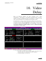
10. VIDEO DELAY
55
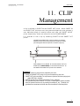
11. CLIP MANAGEMENT
57
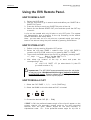
Using the EVS Remote Panel.
How to define a clip?
How to store a clip?
How to recall a clip?
How to playback a clip ?
How to clear a clip?
How to copy / MOVE a clip from the remote panel ?
How to cancel a network copy ?
How to shorten a clip ?
How to restripe the time code of a clip ?
Secondary Menu in Clip Mode
How to clear all clips ?
How to save all clips/Playlists ?
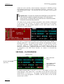
Using the Clip Screen.
Clip Screen – Standard View
Selecting a clip with tablet and stylus
Selecting a clip with the keyboard
The Title Bar
The Function Bar
The Clip Information Area
The Playlist Information Area
The Clip Management Area
Moving and copying Clips and playlists
Clip screen – extended view
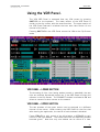
Using the VDR Panel.
VDR Panel – Lower Section
VDR Panel – Upper Section
VDR Panel – Player Window
VDR Panel – Recorder WINDOW
12. KEYWORD MANAGEMENT
2
45
58
58
58
58
59
59
60
61
61
62
62
64
65
66
66
66
67
67
68
72
72
73
74
76
77
77
77
78
80
82
EVS MULTICAM - User’s Manual
Version 8.00
EVS Broadcast Equipment SA – Dec 2005
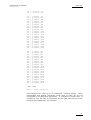
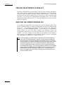
Creating and Selecting the Keyword File.
Creating the keyword file from a PC
Selecting the current keyword file
Editing the keyword file from the multicam application
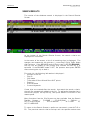
Assigning Keywords using the VGA Screen.
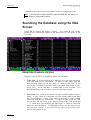
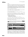
Searching the Database using the VGA Screen.
Definition of Search Criteria
Search Results
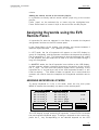
Assigning Keywords using the EVS Remote Panel.
Assigning Keywords in LIST Mode
Assigning Keywords in numeric Mode
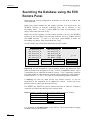
Searching the Database using the EVS Remote Panel.
13. PLAYLIST MANAGEMENT
Standard mode
How to make a playlist?
How to select a playlist?
How to Copy a playlist?
Viewing the VGA Playlist Screen
How to recall a playlist?
How to Browse Quickly Through a playlist?
How to name a playlist?
How to roll a playlist?
How to edit a playlist?
How to delete clips from a playlist?
How to insert clips into a playlist?
How to merge playlists?
How to trim clips into a playlist?
The Auxiliary Audio clip
How Exit The Playlist Mode?
Split Audio Mode
How To Enable Split Audio Editing ?
How To Set Default Video and Audio Transitions?
How To Change Video Effect Duration?
How To Change Audio Effect Duration?
How to set the default mode for extending a transition ?
How To Perform A ‘ V Base’ Edit?
How To Perform An ‘A Base’ Edit?
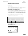
Swap Audio Tracks Mode
Introduction
How To enable the audio swap mode ?
Using the Swap Audio Track Mode in Auto Mode
Using the Swap Audio Track Mode in manual Mode
Deleting swap points
Navigating swap points
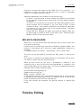
Replace function
Introduction
Entering the replace Function
replace edit mode
replace PLAYBACK mode
Timeline Editing
Introduction
Operations
82
84
84
85
86
88
88
90
91
91
93
94
96
96
96
96
97
99
100
101
101
101
102
103
103
104
104
104
105
106
106
107
108
108
108
108
110
113
113
113
113
115
115
115
115
116
116
116
117
117
118
118
3
Version 8.00
EVS MULTICAM - User’s Manual
EVS Broadcast Equipment SA – Dec 2005
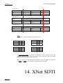
14. XNET SDTI NETWORK
Overview
EVS menu configuration
Connecting to XNet
Disconnecting
Selecting a Server on XNet
Operating with XNet
How to recall/play back a remote clip?
How to name a remote clip?
How to modify IN/OUT points of a remote clip?
How to insert remote clips into a playlist?
How to roll a playlist with remote clips?
How to create local clips with remote records trains?
Mapping network cameras
Network monitoring screen
15. PAINT MODE
Straight Line / Broken Line Drawing
Circle Drawing (Large or small)
Arrow
Color & Density
Erase
Clear
Keyer
Loop
Paint Mode Monitor Display
16. TARGET MODE
Creating a Target Track:
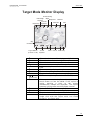
Target Mode Monitor Display
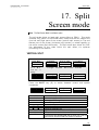
17. SPLIT SCREEN MODE
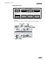
Vertical Split
Horizontal Split
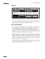
Split MIX
Auto-tracking mode
18. SONY, XTENDD35, ODETICS & VDCP PROTOCOLS
4
120
121
122
123
123
124
126
126
126
127
127
127
128
129
130
132
132
132
132
132
133
133
133
133
134
135
135
137
139
139
141
142
142
143
EVS MULTICAM - User’s Manual
Version 8.00
EVS Broadcast Equipment SA – Dec 2005
Overview
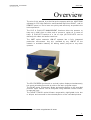
The aim of this manual is to familiarize the operator with the MULTICAM
software for EVS High Definition and Standard Definition LSM-XT, and its
REMOTE panel, so as to learn as quickly and efficiently as possible the
basic operations.
The CLIP & PLAYLIST MANAGEMENT functions allow the operator to
keep up to 4000 clips on disks and of course to replay all or some of
them. A PLAYLIST consists of a list of clips (90 PLAYLISTS can be
defined) with video and audio transitions.
The XNET option networks LSM-XT systems into a fully integrated
production environment. Any clip, recorded by any LSM-XT on the
network is available instantly for editing and/or play-out to any other
operator.
The SPLITSCREEN (horizontal or vertical) option displays simultaneously
two synchronized actions side by side on the main program output.
The PAINT option (Telestrator) draws and applies keying on the recorded
pictures. Sport actions can be analyzed using different colored circles,
arrows and lines.
The TARGET TRACK 1 option follows a target with a highlighted circle, box
or ellipse, and can zoom in the selected portion of the recorded pictures.
1
PAINT and TARGET TRACK options are not available on High Definition XT servers
5
Version 8.00
EVS MULTICAM - User’s Manual
EVS Broadcast Equipment SA – Dec 2005
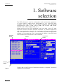
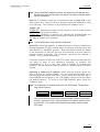
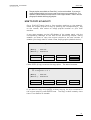
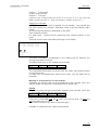
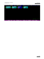
1. Software
selection
Application
window
Message
window
Task bar
6
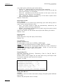
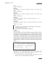
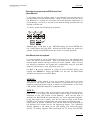
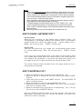
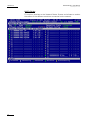
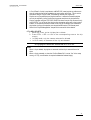
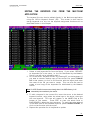
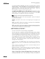
The EVS software is used for configuration and maintenance operations.
It is also used to select which configuration to run, since EVS disk
recorders have the ability to run various standard and customized
configurations. (LSM 1 CAM, LSM 2 CAM, LSM 3 CAM, LSM 4CAM,
TRIPLE LSM, SLSM, SLSM+1CAM, etc.)
When turning on the EVS mainframe, the first step is the PC boot
sequence, and then the EVS software is started. If a default application
has been previously selected, this application will start automatically
after a few seconds if no key is hit. If a default application hasn't been
defined or if the space bar is hit, the system will remain in the EVS main
menu and wait for the operator's next command.
Title bar
Configuration
window
EVS 00.14.11
May 24,2005 16:36:35
Z z
╔ Applications List════╗ ┌ Hardware Revisions ──────┐┌ Network ───────────────┐
║00 LSM Custom
▲║ │8 HCTX Rev A2
││SDTI
OFF
│
║01 LSM 1CAM (CUT)
▒║ │7 Audio Codec Analog RevA2││Net Name EVS XT 1
│
║02 LSM 1CAM (FX)
▒║ │ Audio In/Out
││Net Number 1
│
║03 LSM 2CAM (CUT)
▒║ │ 16 XLR A
││Type
Server
│
║04 LSM 2CAM (FX)
▒║ │6
││DB Size 16000 clips
│
║05 LSM 3CAM (CUT)
▒║ │ #Video Ch
6
│├ Video & Audio ─────────┤
║06 LSM 3CAM (FX)
▒║ │5 COHX HD
││Std 1080i 59.94 NTSC
│
║07 Triple LSM
)
▒║ │4 COHX HD
││Aspect Ratio 4:3 L Box │
║08 LSM 4CAM (CUT)
■║ │3
││SD Mon Out Mon
│
║09 LSM 4CAM (FX)
▒║ │2 COHX HD Genlock
││Audio
ON
│
║10 Super LSM (CUT)
▒║ │1 MTPC Rev A1/R2
││
│
║11 Super LSM (FX)
▒║ ├ Software Releases ───────┤├ Ref & Phase ───────────┤
║12 Super LSM+1CAM
▒║ │LSM:07.00.37
││Ref Type SD Black Burst │
║13 Super LSM+2CAM
▒║ │HCT: 27.56, 23/05/05
││Sync Mode Studio Mode
│
║
▒║ │
││Genlock Ok
│
║
▒║ │
││TC in 16:36:35;27 NTSC │
║
▼║ │
││Phase:0
half pixel
│
╚══════════════════════╝ └──────────────────────────┘└────────────────────────┘
┌ Messages ───────────────────────────────────────────────────────────────────┐
│
│
│
│
└
┘
<F9>Maintenance <F8>Parameters
↑↓ Select <F7> Def App
<Alt-Q>Quit
Please refer to the Technical Reference manual for complete information
regarding the EVS Menu.
EVS MULTICAM - User’s Manual
Version 8.00
EVS Broadcast Equipment SA – Dec 2005
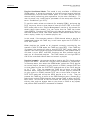
2. Remote
Controller
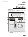
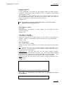
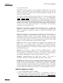
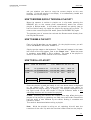
GENERAL LAYOUT
The following diagram shows the REMOTE panel along with a brief
description of each area.
Note: The operational buttons have PRIMARY and SECONDARY functions and are divided
into upper and lower sections. By pressing the SHIFT button you gain access to the
secondary functions
7
Version 8.00
EVS MULTICAM - User’s Manual
EVS Broadcast Equipment SA – Dec 2005
1.
F-Keys & small buttons:
multi-purpose keys
2.
SOFT keys:
with LCD display, enables operator to
enter MULTICAM MENU system
3.
LEVER:
initiates slow motion and playlist replay
4.
JOG DIAL:
used to accurately cue disk recorder
5.
Operational block 1:
PLST
LOOP
BROWSE
INSERT
IN
GOTO IN
OUT
GOTO OUT
TAKE
LEVER
6.
Operational block 2 :
PLAY
NETWORK
LAST CUE
GOTO TC
FAST JOG
MARK
RECORD
RETURN
PRV CTL
PAGE
7.
8
initiates active PLAYLIST
This option records the main output (PGM1) to
the first input (CAM A) of the MULTICAM. This
option is not available on HD systems and the
remote beeps if the operator tries to engage it.
to browse through clips, playlists, cue points
used in playlist management to insert clips into a
playlist
Sets Mark IN at the current position
Goes to the defined Mark IN
Sets Mark OUT at the current position
Goes to the defined Mark OUT
In PGM+PRV mode: swaps cameras on PGM
and PRV monitors
In Multi-PGM mode: toggles between CAM
selection and PGM selection modes.
In Playlist Edit mode: inserts the clip loaded
on the PRV channel into current playlist.
change the lever range to secondary mode (see
setup menu for range selection)
initiates playback
Enters the XNet menu. (connect to other
servers on the network)
Re-cues machine to previous cue point
enables timecode entry, with «F» keys
used with JOG dial for rapid, manual re-cue.
This mode is automatically reset after
PLAY/LIVE commands.
re-usable cue points entry, 256 cycling cues
initiates “E2E” mode
Inside a clip, allows the operator to return to
the same picture inside the record train, if it
still exists.
enables/disables the Preview Control mode
selects current clip page, from 1 to 10.
LCD Display: provides current status of system
EVS MULTICAM - User’s Manual
Version 8.00
EVS Broadcast Equipment SA – Dec 2005
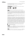
LED COLORS
A selected key lights red.
When a key lights green, it means a value in relation with this key exists.
For example: F1 to F0 keys
Green light means a clip has been stored in relation with the key.
→ Flashing means a clip is being created.
Red light means the clip associated to the key is playing or is
ready to play.
→ Flashing means a clip is being deleted (in network mode)
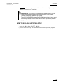
F-KEYS & SMALL BUTTONS
F1
MENU
F2
F3
F4
F5
F6
F7
F8
F9 F10
SHIFT
CLEAR ENTER
provides access to the Secondary Menu. Also used as
CANCEL in some messages when confirmation is required.
MENU
Note: SHIFT + MENU returns to MAIN Menu
enables use of the secondary key functions.
SHIFT
Note: This key remains active even if released, until another key has been hit.
F1
CLEAR
ENTER
-
F10
stores / recalls Clips, recall Playlists and enter Timecode
information.
is a multi-purpose key used to clear CLIPS or PLAYLISTS,
and to clear IN/OUT points
is used to APPEND clips at the end of the current
PLAYLIST, and to validate other options and messages.
9
Version 8.00
EVS MULTICAM - User’s Manual
EVS Broadcast Equipment SA – Dec 2005
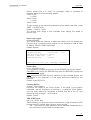
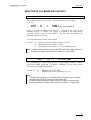
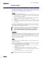
SOFT KEYS
The soft keys have PRIMARY and SECONDARY functions and are divided
into upper and lower sections.
Aud.Met.
Mix.
Sw to IN
Search
Pref
Rst Cam
Cam A
Local
Cam B
Sync Prv
Cam C
2nd Ctrl
Cam D
A
B
C
D
SECONDARY
MENU
MENU
+
SHIFT
OPERATIONAL
MENU
By pressing the SHIFT button you gain access to the secondary functions.
The LCD display is divided in two menus.
To gain access to the secondary menu, press MENU from the remote
controller. The secondary menu is used to define settings that do not
require regular changes, without having to return to the SETUP menu.
To return to the operational menu, press the MENU key again.
To return to the MAIN menu of the Multicam, press SHIFT + MENU.
10
EVS MULTICAM - User’s Manual
Version 8.00
EVS Broadcast Equipment SA – Dec 2005
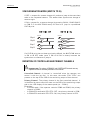
TRANSPORT CONTROLS
JOG DIAL
The JOG DIAL allows the operator to pass into SEARCH mode and thus to
choose exactly the SHORT OUT or SHORT IN image. Move the JOG DIAL
clockwise to search forward and move it counter-clockwise to search
backwards. One revolution of the JOG DIAL will produce a jump of
approximately 35 frames. This number can be multiplied by enabling the
FAST mode. The multiplication factor is defined in the SETUP menu.
Note : The JOG DIAL is also used :
- to set parameters in the SETUP menu. Refer to the SETUP menu section for more
information.
- To BROWSE inside the clips database, the cue points or the current playlist. Refer to
the explanation of the BROWSE function for more details.
The JOG dial is active at all times when the system is in PLAY & RECORD
LEVER
The LEVER is used to start a play or to modify slow motion speed. Its
run can be of two different types regarding the lever mode.
Normal run:
In this mode, the LEVER run goes from 0 up to 100%.
Second range:
The second range is available to play material from –100% to 100% or
from –200 to 200% with a larger step at 0% (see SETUP menu - page 5F4 for selection)
To gain access to this second speed range, press SHIFT + LEVER from
the remote controller.
Note that when SD SUPER MOTION material is loaded on the primary
channel, the lever range as a larger, flat step at 33%. With HD SUPER
MOTION, the step is at 50%.
The lever is also used to adjust speed, and effects type and duration in
Playlist Edit mode.
11
Version 8.00
EVS MULTICAM - User’s Manual
EVS Broadcast Equipment SA – Dec 2005
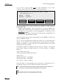
3. MAIN
Menu
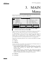
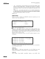
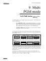
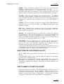
After the boot sequence of the MULTICAM system, the LCD screen of the
Remote Control panel will display the MAIN menu:
2Rec 4Play
LSM Multi-Cam
Ver:06.01.43
F1: 1 Remote
F6: Exit
F2: 2 Remotes
F7: Clear all clips
F3: 3 Remotes
F8: Stop Record
F4: 4 Remotes
F9: Fill Playlist
F5: Char. On/Off
F0: Save Clips+Plist
Split
Paint
PGM+PRV
3 PGM
Target
Setup
Note : If 2 channels are available for the 1st remote, the B key will display 2 PGM. If 3
channels are available, the B key will display 3 PGM.
From any section of the application, except Playlist mode, press SHIFT +
MENU on the first remote control panel to return to the MAIN menu.
The MAIN MENU has special function key operations as shown above, as
well as the «soft» keys options to enter 1PGM, 1PGM+PRV, 2PGM, or
3PGM modes (if available) and to enter the SETUP menu to configure
your remote controller or to add special functions to your application.
Select the corresponding Function key, and then press ENTER to validate
the selection.
F1: 1 Remote
F2: 2 Remotes
If 4 play channels are available, when selecting the 2 Remotes mode, the
operator can chose between 2 configurations :
- 2 play channels for each remote. In this configuration, each remote
panel can select PGM+PRV or 2PGM mode. Each remote panel can
manage video transitions (cut, dissolve, wipe) in PGM+PRV and
PLAYLIST modes.
- 3 play channels for the 1 s t remote and 1 play channel for the second
remote. In this configuration, the 1 s t remote can select PGM+PRV or
3PGM mode and can manage video transitions. The 2 n d remote is
forced to 1PGM mode and can only handle cut transitions.
F3: 3 Remotes
F4 : 4 Remotes
12
EVS MULTICAM - User’s Manual
Version 8.00
EVS Broadcast Equipment SA – Dec 2005
If desired, the MULTICAM system can be run using 1, 2, 3 or 4 EVS
remotes. Depending on the number of play channels available in the
current configuration, 1- , 2-, 3- or 4- remote modes will be available from
the MAIN menu.
F5: Char. On/Off:
enables or disables the on-screen display
(Timecode, Clip ID,…) on the monitoring outputs.
F6: Exit
Exits the MULTICAM software and returns to the
EVS Menu.
Note: This command also runs a Save Clips+Plst process.
F7: Clear all clips
Clears all clips. All clips will be lost.
A confirmation of this command is required:
If some clips are protected, press ENTER to
delete all clips except protected ones, or MENU
to cancel the command
If the system is connected to the XNet, an
additional confirmation is required.
Note: This command is not similar to the “Clear Video Disks”
from the maintenance menu. If you wish to refresh
completely the server, you need to use “Clear Video Disks”
rather than “Clear all clips”.
F8: Stop Record
Stops the record. The REC key will go off and
the F8 function key is now used to restart the
record.
F9: Fill Playlist
This is a «dump» feature which allows all clips to
be «dumped» at the end of the current playlist.
This allows the operator to save all material to
tape, as a backup feature after a show is
complete. You can select in the SETUP menu
which camera angles have to be included in the
Fill Playlist function.
If your clips are currently connected to another
XT server on the network, the clips from that
server will be added to your current playlist.
Make sure the playlist you have selected is an
empty one. This function will append the clips at
the end of an existing playlist.
F0: Save Clips+ Plist
!
Saves all clips and playlists in all banks. Note
that this process is also performed automatically
as a background task every minute (or more
frequently when creating/modifying clips).
Important Note: In order to guarantee the validity of data and clips previously saved,
it is advised to properly exit the application by pressing <Alt>+ <Q> and <ENTER>
from the keyboard, or <F6> and then <ENTER> from the remote panel.
DO NOT TURN OFF THE SYSTEM WHILE THE APPLICATION IS RUNNING.
13
Version 8.00
EVS MULTICAM - User’s Manual
EVS Broadcast Equipment SA – Dec 2005
4. SETUP
Menu
!
Important Note: Prior to using the MULTICAM, the operator should enter the
SETUP menu and set all necessary parameters. If clips are stored with certain
parameters and the operator wishes to change them afterwards, those clips and
playlists will not change. Thus, it is important to set these parameters first.
The SET-UP menu allows the operator to define parameters regarding
some functions. The new parameters are saved as soon as they are
modified.
HOW TO ACCESS THE SET-UP MENU?
Press SHIFT+ MENU key to return to the MAIN menu 1,
Split
Paint
1PGM+PRV
2/3 PGM
Target
Setup
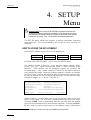
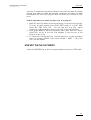
And then press SETUP (SHIFT + D) to enter the SETUP menu.
The setup is divided in sections : clips, playlists, special effects, audio,
control, GPI, etc. When entering the setup, a menu presents these
sections.
Each section can be accessed directly by pressing the
corresponding F_ key. Inside a section, F9 and F10 are used to move to
the previous/next page. When the first/last page of a section is reached,
the next F9/F10 goes to the last/first page of the previous/next section,
so that by starting on the first page and pressing F10, the operator goes
through all pages : p.1.1 Æ p.2.1 Æ p.2.2 Æ…
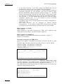
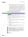
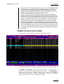
LSM Setup Menu
Main page
[F1]OSD Settings
[F6]EVS Controller
[F2]Record Trains [F7]RS422 Control
[F3]Clips
[F8]GPI
[F4]Playlist
[F9]Special Effects
[F5]Audio
Clr+[F0]Restore Defaults
[Menu]Quit
[Clr+F_]Default
[F0]PgDn
Inside a section, pressing Menu key brings the operator back to the main
menu of the setup. On this page, pressing Menu key exits the setup.
Pressing CLEAR + the corresponding Function key will reset the default
value for the selected section (confirmation required). Pressing CLEAR +
F0 will reset the entire setup menu to the default values (confirmation
1
If you are in PLAYLIST mode, press RECORD first to exit this mode, then SHIFT+MENU to go the Main Menu.
14
EVS MULTICAM - User’s Manual
Version 8.00
EVS Broadcast Equipment SA – Dec 2005
required).
HOW TO SELECT AND TO MODIFY PARAMETERS?
Adjustments are made as follows for most parameters :
Once you’ve reached the desired page, choose the parameter to
be modified by pressing the corresponding Function key & make
adjustment by rotating the JOG knob, then press the
corresponding Function key again.
To restore the default value of a parameter, press CLEAR and the
corresponding Function key.
To return to the main page of the SETUP menu, press MENU
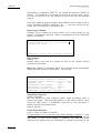
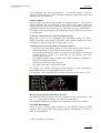
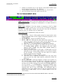
OSD Settings
[F1]Genlock Error Msg
[F2]Disk Error Msg
[F3]Network Error Msg
[F4]Cue number on OSD
[F5]Keyword info
:
:
:
:
:
Yes
Yes
Yes
Yes
No
p.1.1
[Menu]Quit [Clr+F_]Dft [F9]PgUp [F0]PgDn
Genlock Error Msg:
(Yes / No)
Enables or disables the Genlock information on the monitoring output. If
Genlock reference is not correct, the !GkV message appears on the
monitoring output.
Default : Yes
Disk Error Msg:
(Yes / No)
This function displays an error message (!Dsk) on the output monitor
when a disk is faulty.
Default: Yes
Note: The LSM-XT is equipped with a RAID disk array. This means that the operation can
continue seamlessly even with 1 faulty disk. If 1 disk is disconnected during
operation, the “!Dsk” message appears on all monitoring outputs, and another
message appears when the operator shuts down the application, to invite him to
replace the disk and rebuild the RAID array.
Refer to the Technical Reference manual for details on the RAID system and its
maintenance.
Network Error Msg:
(Yes / No)
This function displays an error message (!Net) on the output monitor
when the network connection is faulty and another message (ÆNet) when
the network becomes available again and the system is trying to reconnect.
Default: Yes
Cue number on OSD:
(Yes / No)
When set to “Yes”, the cue number is displayed on the OSD of the
monitoring outputs when a cue point is recalled inside a record train.
15
Version 8.00
EVS MULTICAM - User’s Manual
EVS Broadcast Equipment SA – Dec 2005
Default: Yes
Keyword info :
(No / Yes)
Up to 3 keywords and a ranking can be assigned to every clip. When the
“Keyword info” parameter is set to “Yes”, these keywords and ranking
appears on the OSD of the monitoring outputs when the clip is loaded on
its Short IN point. As soon as the operator starts jogging into the clip or
initiates a playback, this information is removed from the OSD so that the
video content is clearly visible.
Default: No
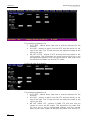
Record Trains
[F1]Auto make clip for
[F2]Auto make clip for
[F3]Auto make clip for
[F4]Auto make clip for
[F5]Auto make clip for
[F6]Resync to TC ref
[Menu]Quit [Clr+F_]Dft
cam
cam
cam
cam
cam
A
B
C
D
E
:
:
:
:
:
p.2.1
Yes
Yes
Yes
Yes
Yes
[F9]PgUp [F0]PgDn
Auto Make Clip for CAM A:
(Yes / No)
Selects the automatic camera creation. When creating clips, the clip
corresponding to the camera on which IN/OUT points have been marked
are always saved. It is possible to save automatically the same action on
the other cameras.
Default: Yes
Auto Make Clip for CAM B:
(Yes / No)
Make clip on CAM B even if no IN or OUT point has been marked on this
one. Default: Yes
Auto Make Clip for CAM C:
(Yes / No)
Make clip on CAM C even if no IN or OUT point has been marked on this
one. Default: Yes
Auto Make Clip for CAM D:
(Yes / No)
Make clip on CAM D even if no IN or OUT point has been marked on this
one. Default: Yes
Auto Make Clip for CAM E:
(Yes / No)
Make clip on CAM E even if no IN or OUT point has been marked on this
one. Default: Yes
Resync to TC ref:
The Multicam application uses an internal table to reference all time code
discontinuities detected on the LTC input of the system. This table is
used to match a recorded field to it s time code, and has a limited number
of 1024 entries. When the number of TC discontinuities is too important
and the internal TC table is full, a “!TC” warning appears on the OSD of
the monitoring outputs and the system swit ches to the “internal time code
16
EVS MULTICAM - User’s Manual
Version 8.00
EVS Broadcast Equipment SA – Dec 2005
mode”, i.e. it start implementing its internal time code reference based on
the genlock and the last external TC value read before the TC table is
full. This means that any time code discontinuity occurring after the TC
table is full is ignored, the system assuming the TC is continuous from
that moment on. The operator can clear this internal TC table by calling
the “Resync to TC ref” function. Clearing the TC table will delete all
reference to previous time code jumps, and synchronize the internal TC to
the time code read on the LTC input of the server. From that moment on,
the system will assume that the time code was continuous for previously
recorded material, and will take into account the new time code
discontinuities.
Note that the above explanation is only valid for record trains. For clips,
the time code of the first field of the clip is memorized at the creation of
the clip, and the timecode is always assumed continuous inside the clip.
Clearing the internal TC table will consequently have no effect on the
time code of recorded clips.
To call the “Resync to TC ref” function, simply press the F6 key and the
function is immediately performed.
Record Trains
p.2.2
[F1]Guardbands
: 05s00fr
[F2]Default clip duration : 04s00fr
[F3]Mark cue points
: Live
[F4]Preroll
: 02s00fr
[F5]Record trains OUTs
: Play Through
[F6]Internal loop mode
: Video+Audio
[Menu]Quit [Clr+F_]Dft [F9]PgUp [F0]PgDn
Guardbands:
(from 00s01fr to 60s00fr)
the amount of «guardband» before and after clips.
Default : 05s00fr
Note: A clip is created immediately when the operator saves it by pressing the F_ key on
the remote, and is thus limited by the amount of material recorded at that time. This
might create a shorter guardband that indicated in the setup, if the material recorded
beyond the OUT point is shorter than the default guardband duration. The only
exception is the creation of a clip by marking an IN point but no OUT point. In this
case, the clip has a duration defined by the “Default clip duration” parameter of the
setup, and the guardband beyond the OUT point has the duration defined by the
“guardband” parameter. If the material recorded when the operator presses the F_
key to save the clip using this technique is not long enough, the F_ key will blink an
the clip will not be available until the required duration, including the guardband, is
recorded.
Default Clip Duration:
(Disable, or 00s01fr to 12s00fr)
sets the duration of clips created with only IN point or only OUT point.
When set to “Disable”, both IN and OUT points are required to be able to
create a clip.
Default: 04s00fr
Mark Cue Points:
(Live / Playback)
17
Version 8.00
EVS MULTICAM - User’s Manual
EVS Broadcast Equipment SA – Dec 2005
Live: memorizes cue points based on the time code of the LIVE input.
Playback: memorizes cue points based on the timecode of the field
loaded on the main play channel.
Default: Live
Pre-Roll:
(0s01fr to 5s00fr)
Pre-roll duration used when recalling a cue point.
Default : 0s05fr
Record Train OUTs:
(Play through / Freeze)
When this parameter is set to FREEZE, and an OUT point is marked in a
record train, the Multicam will countdown to the OUT point and
automatically freeze on that picture (if the POSTROLL mode is disabled)
or on that picture + the post-roll duration (if the POSTROLL mode is
enabled) when replaying that section. If set to “play through” it will still
countdown to the OUT point, but will keep playing through this point.
In a clip, the Multicam always freezes on the OUT point (or OUT point +
post-roll duration when POSTROLL mode is enabled).
Default: Play through
Internal Loop Mode:
(Video + Audio / Video only)
This parameter defines what components of PGM1 output must be
recorded back into the server when the LOOP mode is engaged.
Video + Audio: both video and audio signals of PGM1 are recorded back
into CAM A input.
Video only: only the video signal of PGM1 is recorded back into CAM A
input. This allows the operator to continue the record of live audio tracks
during the LOOP process. This can be useful to add music, voice or live
sound to an edit for example.
Default: Video+Audio
Clips
p.2.3
[F1]Make Clip rem. Trains: Ctrled Cams
[Menu]Quit [Clr+F_]Dft [F9]PgUp [F0]PgDn
Make Clip rem. trains:
(Ctrled Cams / All cams)
By default, only controlled remote cameras are clipped. This parameter
allows to clip all cameras of a remote server if at least one trains of that
server is controlled.
Clips
[F1]Protect pages : 1 2 3
[F2]Confirm delete clips
[F3]Auto name clips
[F4]Clip post-roll
[F5]Call channel VGA
18
4
:
:
:
:
p.3.1
5 6 7 8 9 10
No
Disable
02s00fr
Disable
EVS MULTICAM - User’s Manual
Version 8.00
EVS Broadcast Equipment SA – Dec 2005
[F6]Clip edit by network : Disable
[Menu]Quit [Clr+F_]Dft [F9]PgUp [F0]PgDn
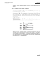
Protect page:
(No, or select one or more clip pages from 1 to 10)
This function allows users to protect clips stored on selected pages from
accidental deletion. These clips are also protected when using the
CLEAR ALL CLIPS function from the main menu of the remote panel.
Press the F1 key to edit this parameter, then press the F_ key
corresponding to the page number you want to protect/unprotect.
Protected pages will be highlighted on the LCD and the corresponding F_
key lights red. F_ keys of unprotected pages light green. To validate
your selection, press ENTER. The LCD display indicates the progress of
the status update for the selected pages. This might take several
seconds, depending on the number of clips in the pages that must be
updated. In the above example, pages 3, 5 and 6 are protected.
Default: No
Note: When doing a “Clear All Clips” from the main menu of the remote panel, protected
clips will not be deleted. When doing a “Clear Video Disks” from EVS Maintenance
Menu, all clips are deleted, including protected ones !!
Note: The OSD will display a key icon next to the clip number when the clip is protected.
Confirm delete clip:
(No / Yes)
No: clips are deleted immediately
Yes: a confirmation is required when deleting clips, either from the
remote or from the keyboard.
Default: No
Note: This parameter does not apply to the CLEAR ALL CLIPS command (Main Menu)
which already has its own confirmation message.
Auto name clips:
(Disabled / TC IN / CAM Name)
If this function is enabled, the timecode of the IN point of the clip, or the
name of the record channel, will automatically be used to name the clip
upon creation.
Default: Disabled.
Clip post-roll:
(00s00fr to 30s00fr)
When the post-roll function is enabled from the secondary clip menu, the
clip will play through its OUT point for a duration defined by the post-roll
parameter. This is also valid inside record trains if the Record Train
OUTs parameter is set to Freeze.
Default: 02s00fr.
Call Channel VGA:
(Disabled / Enabled)
Disable or enable the CALL CH function on the VGA Clip Screen, that
allows the operator to select on which PGM channel the clips called from
the keyboard/tablet and VGA should be loaded.
19
Version 8.00
EVS MULTICAM - User’s Manual
EVS Broadcast Equipment SA – Dec 2005
Clip Edit by Network:
(Disabled / Enabled)
If this function is enabled, other users on the network can trim, rename,
delete, … your clips, or modify the keywords and ranking assigned to your
clips. If disabled, only the local operators can modify or delete clips on
the server and edit their metadata.
Default: Disabled.
Clips
p.3.2
[F1]Keywords file : Football [F8]Delete
[F2]Keyword Mode
: List
[F3]PUSH Machine 1 : Peter
#04
[F4]PUSH Machine 2 : Paul
#05
[F5]PUSH Mode
: Short
[F6]PUSH Receive Pg: 1 2 3 4 5 6 7 8 9 0
[Menu]Quit [Clr+F_]Dft [F9]PgUp [F0]PgDn
Keywords File:
(--------, SERVER, or name of keywords files present on the system)
Selects the keywords file to use to assign keywords to clips or to search
the clips database. If set to “--------“, no keywords file is selected, and
the keywords assignment and related sear ch functions are not available.
If set to “SERVER”, the keywords file sent by the active network server to
all systems on the network will be used. Other file names will appear if
keywords files (files with a .KWD extension) have been loaded in the
C:\MULTICAM\KWD directory of the system.
Keyword files can be
imported using the “Import/Export Setup Files” function of the
Maintenance Menu of the EVS Menu (refer to the “Technical Reference
for XT Server” manuel for details). [F8] key allows the operator to delete
the selected file (confirmation required). Details about the keywords file
format and keywords-related functions are available further in this
manual.
Default: -------Keyword Mode:
(List, Numeric)
Selects the keyword assignment/search mode on the EVS remote panel.
List will display the keywords by groups of 8 on the LCD of the remote
panel and the operator can select them with the corresponding F_ key ;
Numeric doesn’t display the keywords list on the LCD, but allows the
operator to enter directly the keyword ID using the F_ keys. The Numeric
mode is faster when the operator knows the position of the keywords
inside the keywords file, either from memory, using the VGA keyword
screens, or using a print of the keywords list.
Default: List
PUSH Machine 1 & 2
(network system name and number)
Selects which machine(s) on the network clips must be sent to when
using the PUSH function on the EVS remote panel.
Default : -------- #-Users can defined two push machines : (F3): PUSH Machine 1, (F4):
PUSH Machine 2. The clips will be pushed in sequential order.
PUSH Receive Page:
20
EVS MULTICAM - User’s Manual
Version 8.00
EVS Broadcast Equipment SA – Dec 2005
(Select one or more clip pages from 1 to 10)
Selects the page of your machine where clips sent to you by other
network operators using the PUSH function must be stored. Press the F5
key to edit this parameter, then press the F_ key corresponding to the
page number you want to select/unselect.
Selected pages will be
highlighted on the LCD and the corresponding F_ key lights red. F_ keys
of unselected pages light green. To validate your selection, press
ENTER.
Default : Page 5
Clips
p.3.3
[F1]PLST Receive Pg: 1 2 3 4 5 6 7 8 9 0
[F2]Protocol receive Page : 06
[F3]Default Xfile : Xfile
#31
[F4]Grab image
: Disable
[F5]Browse button : Browse
[F6]Reset Archive Status
[Menu]Quit [Clr+F_]Dft [F9]PgUp [F0]PgDn
PLST Receive Page:
(Select one or more clip pages from 1 to 10)
Selects the page of your machine where clips received when using the
PLST+CLIPS copy function must be stored. This function allows the
operator to automatically create a local copy all network clips of a playlist
when copying a local or network playlist. Refer to the description of the
Playlist copy function for details.
Clip pages can be assigned
simultaneously as PUSH and PLST Receive Pages.
Default : Page 10
Protocol receive page:
Default : Protocol receive page : 6
This setting defines from which page the clips created by protocol are
stored. When a page is full, clips are stored on the next page.
Only clips created on this page (and the other protocol pages if the first
page is full) are visible for protocols.
Default Xfile:
(Xfile name and network number)
Defines the Xfile where clips must be sent when using the ARCHIVE
function from the EVS remote panel or VGA screens.
Default : -------- #-Grab image:
Default : disabled.
When the function is enabled and a def ault x-file has been assigned, the
grab function is coupled with the ‘mark’ key on the remote. Each time the
‘Mark’ key is used, a cue point is marked and a command is sent to the xfile to save that image.
The grab can also be activated on the keyboard with the combination :
‘ctrl + G’.
Browse button : Browse/Sort-TC
Default : Browse
Allows the user to convert the function of the Browse button. In the
default Browse mode, it will activate the Playlist Browse directly. If the
21
Version 8.00
EVS MULTICAM - User’s Manual
EVS Broadcast Equipment SA – Dec 2005
assignment is changed to SORT-TC, the system will perform a SORT-TC
directly. The system will not prompt the user with a select menu, and it
will use the current TC on the channel to search with the last selected
criteria.
If the user wants to perform a search with different criteria (Search Net or
Local, StartDate, EndDate, CAM/CLIP, etc… ) the user should use the
normal Sort-TC selection in the upper menu.
Reset Archive Status:
Pressing F6 will resets the archive status of all clips present on the
system. Confirmation required. Refer to the description of the ARCHIVE
function for details.
Timeline
p.3.4
[F1]TL Receive Pg: 1 2 3 4 5 6 7 8 9 0
[F2]Mono per Track : 1
[Menu]Quit [Clr+F_]Dft [F9]PgUp [F0]PgDn
Receive Page:
Default : 0
Selects where clips that are created as part of the timeline editing
process will be stored.
Mono Per Track will eventually allow more flexible audio management
inside the audio track of Timeline Edit – not used yet.
Playlist
p.4.1
[F1]Video effect duration : 00s10fr
[F2]Audio effect duration : Lock to Vid.
[F3]Wipe type
: Vert.
L>R
[F4]Default plst speed
: Unk.
[F5]Insert in playlist
: After
[F6]Confirm Ins/Del clips : No
[Menu]Quit [Clr+F_]Dft [F9]PgUp [F0]PgDn
Video Effect Duration:
(0s00fr to 20s00fr)
sets the duration of video transition effect. Used as default value in
playlist edit mode. Note that the duration of the video transition when
using the TAKE button in 1PGM+PRV mode has its own parameter in
another section of the setup menu.
Default: 00s10fr
Audio Effect Duration:
(Lock to video, or 0s00fr to 20s00fr)
This parameter is only used when Split Audio Editing is enabled. It sets
the duration of audio transition effect. Used as default value in playlist
edit mode. If split audio editing is disabled, the video and audio
transitions will always have the same duration, based on the setup for the
22
EVS MULTICAM - User’s Manual
Version 8.00
EVS Broadcast Equipment SA – Dec 2005
video transition, whatever the value of the Audio Effect Duration defined
in the setup menu. If this parameter is set to “Lock to video”, you will not
be able to define different durations for the audio and video transition
inside a playlist, even if the Split Audio Editing is enabled.
Default: Lock to video
Wipe Type:
(Vert. L>R / Vert. R>L)
Selects vertical wipe effects from Left to Right or from Right to Left.
Default : Vert (L>R)
Default Plst Speed:
(Unknown, then from 0% to 100%)
Default speed used for clips entered into playlist. Unknown means that
the speed of the previous clip in the playlist will be used as a reference
for the current clip. 0% will force the playlist to pause at the end of the
previous clip.
Default: Unknown
Insert in Playlist:
(After / Before)
selects the mode for «INSERT» function of playlist : the new clip will be
inserted after or before the current clip in the playlist.
Default: After
Confirm Ins/Del clip:
(No / Yes)
If enabled, a confirmation will be required everytime the operator wants to
add a clip to the playlist or remove a clip from the playlist.
Default: No
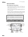
Playlist
p.4.2
[F1]Split audio editing
: Disable
[F2]Extend split transition: End Cut
[F3]Swap audio tracks
: Auto
[F4]Playlist loop
: No
[F5]Load playlist
: Always
[F6]Playlist auto fill
: All Cam
[Menu]Quit [Clr+F_]Dft [F9]PgUp [F0]PgDn
Split Audio :
(Disable / Enable)
This parameter enables or disables the Split Audio Editing option in
Playlist mode. Changing this parameter modifies the display on the
monitoring outputs and adds special function keys on the LCD screen to
define different transition points and durations on the video and audio
tracks.
Default: Disable
Note: A specific license code (option 112 : Playlist Mgmt Advanced) is required to enable
split audio editing.
Extend split transition:
(Center (on) Cut / End (on) Cut / Start (on) Cut / Ask)
Determines how the transition should be extended when modifying the
transition duration on the audio or video track only. This parameter is
23
Version 8.00
EVS MULTICAM - User’s Manual
EVS Broadcast Equipment SA – Dec 2005
only useful when performing split audio editing.
- Center Cut : extend equally on both sides of the transition
- End Cut : extend the beginning of the transition to the left so that the
end of the transition is unchanged
- Start Cut : extened the end of the transition to the right so that the
beginning of the transition is unchanged
- Ask : allows the operator to select any of the above options when
editing the duration of the transition
Default : Center Cut
Swap audio tracks:
(Auto / Manual)
This parameter is only useful when performing split audio editing with at
least 2 mono audio tracks per video.
- Auto : the audio tracks to swap are automatically selected by the
application when inserting a swap point.
- Manual : the operator can define which audio tracks he wants to swap
when inserting a swap point.
Refer to the section of the manual about Split Audio Editing for details.
Default : Auto
Playlist Loop:
(Yes / No)
Allows playlist to loop and replay continuously.
Default : No
Load Playlist:
(Always / Conditional)
This parameter is only used in 2PGM or 3PGM mode.
Always: loads the selected playlist to PGM1 and PRV to PGM2
Conditional: loads playlist on the selected PGM only if only 1 channel is
active when entering the PLST EDIT mode. Allows to load and play
multiple playlists using a single remote panel.
Default: Always
Playlist Auto Fill:
(All Cam / Prim+Sec / Primary / Secondary / Cam A / Cam B / Cam C /
Cam D / Cam E / Cam F)
Selects which camera angles will be used when using the Playlist Auto
Fill function from the main menu of the remote.
Default : All Cam
Audio
[F1]Audio slow motion
: No
[F2]Lipsync value(ms)
:
0
[F3]Audio meters on OSD
: Yes
[F4]Audio meters adj.(db) :
0
[F5]Aux track output : Prv
p.5.1
[Menu]Quit [Clr+F_]Dft [F9]PgUp [F0]PgDn
Audio Slow Motion:
(Yes/No)
Playback or mute the audio track when playing off-speed (speed different
then 100%).
Default: No (off-speed audio is muted)
24
EVS MULTICAM - User’s Manual
Version 8.00
EVS Broadcast Equipment SA – Dec 2005
Lipsync value(ms):
(-22 to 17 ms)
Lipsync parameter is the delay (in ms) between video and audio signals.
A positive value means video is ahead of audio. A negative value means
audio ahead of video.
This parameter is also available from the Channel Parameters option of
the EVS Maintenance Menu. Changing the Lipsync value in the SETUP
menu will update it in the EVS menu and vice versa.
Default: 0 ms
Note: This adjustment is done during the RECORD process. A new Lipsync value will
apply for the next recorded pictures only.
Audio Meters on OSD:
(Yes / No)
Enable/Disable the display of audio meters at the bottom of each
monitoring output.
Default: Yes
Audio Meters Adj.(dB):
(-12 to +12 by 2 dB steps)
Adjust the sensitivity of audio meters on the OSD of the monitoring
outputs. A positive value means that the meters will be more sensitive.
Default: 0 dB
Aux Track Output:
(Prv / Prv&7-8/15-16 / PGM)
Defines to which audio outputs the Aux track of the playlist will be played
out of.
Prv : the Aux track will use the audio outputs normally assigned to the
PRV channel. If no Prv channel is available, the Aux track will not be
assigned to any audio output.
Prv&7-8/15-16 : the Aux track will use the audio outputs normally
assigned to the PRV channel if there is one, plus all the audio outputs
from 7-8/15-16 that have not yet been assigned to another channel. Use
this option if you need an aux track without PRV channel available.
PGM : the Aux track will use the audio outputs normally assigned to the
PGM channel.
Default: Prv
Audio
p.5.2
[Menu]Quit [Clr+F_]Dft [F9]PgUp [F0]PgDn
This page is intentionally left blank and is reserved for future
developments
EVS Controller
p.6.1
[F1]Effect duration for Take : 00s05fr
25
Version 8.00
EVS MULTICAM - User’s Manual
EVS Broadcast Equipment SA – Dec 2005
[F2]Fast jog
[F3]PGM Speed/Var Max
[F4]Lever engage mode
[F5]Second lever range
[F6]Recall clip Toggle
[Menu]Quit [Clr+F_]Dft
: 20x
: 50%
: Direct
: -100% <-> +100%
: Enable
[F9]PgUp [F0]PgDn
Effect Duration for Take:
(00s00fr to 20s00fr)
Defines the duration of the transition when using the TAKE key to chain 2
sequences in PGM+PRV mode.
Default: 00s05fr
Fast Jog:
(01 to 20 times)
sets the increment of the jump when in Fast Jog mode.
Default: 20x
Pgm Speed/Var Max:
(1 – 100%)
during playback, if PGM Spd or VarMax has been enabled in the
secondary menu of the remote, the lever range will be adapted so that :
- the only playback value for any position of the lever other than 0, is
the one specified by this parameter in the setup (PGM Spd mode ON),
- or the speed range defined by the lever is limited to the value
specified by this parameter (VarMax mode ON).
Default: 050%
Lever Engage mode:
(Direct / Current speed)
The speed variation depends on the position of the T-Bar lever.
Direct mode: the lever will engage directly when moved, resulting in a
speed jump to the desired speed determined by the lever arm position.
Current speed mode: the lever will only engage when it reaches the
current playback speed, whereas a move of the lever arm in the opposite
direction of the current speed will result in a direct speed change.
Default: Direct
Second Lever Range:
The T-Bar lever can be used in normal mode: to play back clips at slow
26
EVS MULTICAM - User’s Manual
Version 8.00
EVS Broadcast Equipment SA – Dec 2005
motion speed from 0 to 100%. Or secondary range is available to
playback material at the following speeds :
-100% 100%
0 200%
-200% 200%
0 400%
-400% 400%
To gain access to the secondary speed from the remote controller, press
SHIFT + LEVER/TAKE.
Default: –100% to +100%
The second lever range is also available when editing the speed of
playlist clips.
Recall clip toggle:
(Enable/Disable)
This option allows the operator to select the camera of a clip through the
Function keys. Pressing several times the F key browses to CAM A, CAM
B, CAM C, CAM D, CAM E and CAM F.
Default: Enable
EVS Controller
p.6.2
[F1]Record key
: Start REC + Live
[F2]Pointing device : Tablet
[F3]VGA & RMT Sync : No
[F4]PGM/PRV Mode
: Enable
[Menu]Quit [Clr+F_]Dft [F9]PgUp [F0]PgDn
Record Key:
(Live / Start REC+Live)
This parameter changes the function of the RECORD key on the remote.
Start REC+Live: Hitting the RECORD key starts the RECORD process and
switches to LIVE mode.
Live: hitting the RECORD key only switches to last recorded picture, but
the record is not restarted if it has been previously stopped by the
operator.
Default: Start REC+Live
Pointing Device:
(Tablet / Touch Screen)
Initializes the Tablet or the Touch Screen. If the tablet is not properly
calibrated, use this function to re-initialize it. If using the Touch Screen,
this one must always be connected to RS422 port #6 of the XT, and
defined as such at page 7.1 of the setup.
Default: Tablet
VGA & RMT Sync :
(No, Yes, Server Nbr)
Select whether and how the current clips machine, page and bank of VGA
screens and EVS remote panel must be synchronized.
- “No” : clips machine, page and bank can be selected independently on
the VGA screen and on the EVS remote panel ;
27
Version 8.00
EVS MULTICAM - User’s Manual
EVS Broadcast Equipment SA – Dec 2005
-
“Yes” : clips machine, page and bank are synchronized between VGA
screen and EVS remote panel. Connecting to the clips of a network
machine or coming back to the clips of the local machine, or selecting
a new page or bank on one side will be automatically reflected on the
other ;
- “Server Nbr” : clips pages and banks can be selected independently
on VGA and remote, but connecting to the clips of a network machine
or coming back to the clips of the local machine on the VGA or remote
panel will automatically reflect on the other.
Default : No
PGM/PRV Mode
Default : Enable
Allows the user to disable the PGM/PRV mode from appearing on the
remote’s main menu ([A] Button).
Mapping network cam
[F1]Authorize cam mapping
Cam A
Cam B
[F3]Cam C
[F4]Cam D
:
:
:
:
:
p.6.3
Yes
Local
Local
CamA/01
CamB/01
[Menu]Quit [Clr+F_]Dft [F9]PgUp [F0]PgDn
Note : This is a software option.
Allows to map network trains to unsued local camera position up to
camera D. If the camera is local (cam A and B on the example), no F keys
are assigned to it. If the position can be used by a network camera, the F
key is available. Select a cam position and jog with the dial to reach the
desired network camera to map.
Refer to the corresponding section is the SDTI network chapter for more
information.
Port
Device/Protocol
p.7.1
RS422 #1 EVS Remote
[F7]ID Type:
[F2]RS422 #2 EVS Remote
ID LSM
[F3]RS422 #3 EVS Remote
[F4]RS422 #4 Sony BVW75
[F5]RS422 #5 Sony BVW75
[F6]RS422 #6 Touch Screen
[Menu]Quit [Clr+F_]Dft [F9]PgUp [F0]PgDn
This page is used to define what type of device/controller is connected to
each RS422 port of the XT.
RS422 #1:
(EVS Remote)
When working in LSM base configuration, the first RS422 port must
always be connected to an EVS remote. No other possible selection
RS422 #2:
(EVS Remote, Sony BVW75, XtenDD35, Odetics, Louth VDCP, EVS
28
EVS MULTICAM - User’s Manual
Version 8.00
EVS Broadcast Equipment SA – Dec 2005
AVSP, ---------)
Default : EVS Remote
RS422 #3:
(EVS Remote, Sony BVW75, XtenDD35, Odetics, Louth VDCP, EVS
AVSP, ---------)
Default : EVS Remote
RS422 #4:
(EVS Remote, Sony BVW75, XtenDD35, Odetics, Louth VDCP, EVS
AVSP, ---------)
Default : Sony BVW75
RS422 #5:
(Sony BVW75, XtenDD35, Odetics, Louth VDCP, EVS AVSP, ---------)
Default : Sony BVW75
RS422 #6:
(Sony BVW75, XtenDD35, Odetics, Louth VDCP, EVS AVSP, Touch Screen,
---------)
Default : Touch Screen
Note:
- It is preferable to assign all EVS remotes to the first RS422 ports. Avoid interleaving
protocols and EVS remotes in this list.
- The Touch Screen can only be assigned to RS422 port #6.
ID Type:
(UmID, ID LSM)
Defines the type of clip ID used by RS422 protocols (XtenDD35, Odetics,
Louth VDCP, EVS AVSP) to identify clips. ID LSM identifies clips using
their page, bank, clip and camera number (ex : 245C) ; UmID is another
identifier that is either assigned by the protocol when creating the clip (ex
: CLP00001), or defined automatically by the Multicam when the clip is
created using the EVS remote panel, or when the protocol doesn’t specify
this ID. When it is defined by the Multicam, the UmID is a coded ID (ex :
3x2QogRW) that is unique for every clip created on any XT server, and is
based on the serial number of the server, and creation date and time of
the clip.
Default : UmID
Special Control Settings
p.7.2
Main
RS422
Second. RS422
PGM1:
EVS Remote -- [F5]Sony BVW75 04
PGM2:[F2]EVS Remote –- [F6]Sony BVW75 05
PGM3:[F3]EVS Remote –- [F7]---------- -PGM4:[F4]EVS Remote –- [F8]---------- -[Menu]Quit [Clr+F_]Dft [F9]PgUp [F0]PgDn
This page is used to define which device/controller can control which
PGM channel.
For each PGM channel, you must define the main
controller, selecting from the list defined on page 7.1.
-
In LSM mode, the main controller for PGM1 must always be an EVS
remote. This can not be changed by the operator.
29
Version 8.00
EVS MULTICAM - User’s Manual
EVS Broadcast Equipment SA – Dec 2005
-
-
If the main controller is an EVS remote, the RS422 port will be
automatically assigned and is not specified by the operator.
If the main controller is an EVS remote, it is then possible to specify a
secondary controller for that channel, that can be either a Sony
BVW75, XtenDD35 or Odetics protocol defined on page 7.1. The EVS
remote controlling that channel can then decide at any time to pass
the control to, or to retrieve the control from the secondary controller.
Like for page 7.1, all EVS remotes must be the first in the list of Main
controllers, without gap.
It is not allowed to have a protocol
preceding an EVS remote in this list.
A protocol (other than EVS AVSP protocol) can only be assigned to 1
channel at a time.
EVS AVSP protocol can be assigned to several channel
simultaneously. If you need to assign some channels to an Air Box,
you must set the main controller for these channels to EVS AVSP.
Main Controller for PGM1:
(EVS Remote)
When working in LSM base configuration, PGM1 main controller must
always be an EVS remote. No other possible selection
Main Controller for PGM2/3/4:
(EVS Remote + list of protocols-RS422 ports defined on page 7.1)
Default : EVS Remote
Secondary Controller for PGM1/2/3/4:
(list of Sony BVW75, XtenDD35 and Odetics protocols defined on page
7.1)
Available only if the main controller for that channel is an EVS remote.
Default for PGM1 : Sony BVW75 on RS422 #4
Default for PGM2 : Sony BVW75 on RS422 #5
Default for PGM3 & 4 : ---------- -Special Control Settings
p.7.3
Main
RS422
Second. RS422
PGM5:[F1]---------- -- [F5]---------- --
[Menu]Quit [Clr+F_]Dft [F9]PgUp [F0]PgDn
Multicam is now capable of operating in LSM Base Config with 5 play
channels assigned. This added Protocol assignment page is where the
user can define the protocols and ports to manage this channel.
The LSM remote by itself cannot control 5 PGM channels at one time, two
remotes or devices must be used.
Special Control Settings
Control type
OSD Display
PGM1:[F1]Parallel
[F5] Main
PGM2:[F2]Exclusive
PGM3:[F3]Exclusive
PGM4:[F4]Exclusive
p.7.4
[Menu]Quit [Clr+F_]Dft [F9]PgUp [F0]PgDn
30
EVS MULTICAM - User’s Manual
Version 8.00
EVS Broadcast Equipment SA – Dec 2005
Default : Exclusive
This page allows the user to now allow channels to either be controlled in
‘Exclusive’ control (same as was allowed in the past with 2 n d Control
Mode) or in Parallel Mode.
In Parallel mode, the user can def ine which device will manage the OSD
display characters.
Special Control Settings
Control type
OSD Display
PGM5:[F1]Exclusive
[F5] Main
p.7.5
[Menu]Quit [Clr+F_]Dft [F9]PgUp [F0]PgDn
This page is the same as Page 7.4, but assigns PGM5
GPI In Settings
p.8.1
GPI#
Channel/Device Port
Function
1
[F1]PGM1
-- [F5]Play
2
[F2]PGM2
-- [F6]Play
3
[F3]PGM3
-- [F7]Play
4
[F4]PGM4
-- [F8]Play
[Menu]Quit [Clr+F_]Dft [F9]PgUp [F0]PgDn
GPI In Settings
p.8.2
GPI#
Channel/Device Port
Function
5
[F1]RMT1
-- [F5]Play
6
[F2]RMT1
-- [F6]Next
7
[F3]RMT1
-- [F7]Skip
8
[F4]RMT1
-- [F8]Pause
[Menu]Quit [Clr+F_]Dft [F9]PgUp [F0]PgDn
These 2 pages define the settings for the GPI inputs of the XT server.
For each GPI input, the operator has the possibility to define :
- the channel that the GPI will affect or the device that the GPI is
assigned to. A device can be EVS remote #1 or one of the protocols
defined in page 7.1 (if some GPI must be used by the Air Box in a
mixed configuration LSM+Air Box, or if a GPIs must trigger some
actions on a channel controlled by a Sony protocol, etc.). If the
operator selects EVS Remote #1, the GPI will trigger the selected
action on all channels controlled by that remote.
- the function that the GPI will trigger : Play, Pause, Recue, Previous
(recue to previous clip inside the playlist), Next (goto next clip inside
the playlist), Skip (skip the next clip in the playlist), -------- (no action
is taken). If a GPI is assigned to an AVSP protocol for use with the
EVS Air Box or Air Edit application, the function of this GPI will be
defined by the Air Box / Air Edit software.
31
Version 8.00
EVS MULTICAM - User’s Manual
EVS Broadcast Equipment SA – Dec 2005
The representations of pages 8.1 and 8.2 of the LCD screen shows the
default values for GPI inputs 1 to 8. For the pinout of the GPI connector
and wiring instructions, please refer to the XT Technical Reference.
GPI Setting
[F1]GPI delay : Disable
p.8.3
[Menu]Quit [Clr+F_]Dft [F9]PgUp [F0]PgDn
GPI Delay:
(Disable / 00s01fr to 02s00fr)
Defines the delay for the XT server to react to the reception of a GPI
trigger.
Default : Disable (immediate reaction)
Special Effect
p.9.1
[F1]Paint/Target trans. : 00s05fr
[F2]Set color for
: Cursor
[F3]Color : White [F4]Y : 240
[F5]U : 128
[F6]V : 128
[F7]Split Screen Tracking: No
[Menu]Quit [Clr+F_]Dft [F9]PgUp
Paint/Target Transition:
(0s01fr to 5s00fr)
Sets the duration of the dissolve effect for the key in Painting and Target
Tracking modes.
Default : 0s05fr
Set color for:
(Cursor / Target Border / Wipe / Split)
Applies the default color to a specific tool: to the cursor, to the border of
the wipe effect or to the delimiter of the split screen.
Default: Cursor.
Color: (white, black, custom)
defines the color to assign to the cursor/wipe/split.
Default: white
Custom Color :
F3, F4, and F5 are used to set the border color for the split screen, the
wipe effect and the cursor
Custom Y : (0 – 360)
Default : 240
Custom U : (0 – 128)
Default : 128
32
EVS MULTICAM - User’s Manual
Version 8.00
EVS Broadcast Equipment SA – Dec 2005
Custom V : (0 – 128)
Default : 128
SplitScreen Tracking:
(Yes/No).
enables or disables the auto-tracking inside the Split Screen effect.
Default: No
33
Version 8.00
EVS MULTICAM - User’s Manual
EVS Broadcast Equipment SA – Dec 2005
5. SETUP
Screen
The VGA Setup screen contains some parameters from the Setup Menu of
the remote that are useful to adjust when working in a mode where no
remote panel is used.
HOW TO ACCESS THE SET-UP MENU?
The VGA Setup screen is available by pressing simultaneously SHIFT +
F2 on the keyboard with CAPS LOCK disabled. The Setup screen is not
accessible if CAPS LOCK is ON.
Some parameters included in the VGA Setup screen are common with
those in the Remote Setup Menu. Therefore, a modification in the VGA
Setup Screen is reflected immediately in the Remote Setup Menu, and
vice-versa.
Only some settings of the Remote Setup Menu are included in the VGA
Setup screen. The others have not been included since they are relative
to functions that are specific to the EVS remote, and are not useful when
this panel is not used (Video Delay and Slave modes).
Some parameters are specific to the VGA Setup Screen, and are not
present in the Setup Menu of the EVS remote panel.
Date Format:
(dd/mm/yy)
34
EVS MULTICAM - User’s Manual
Version 8.00
EVS Broadcast Equipment SA – Dec 2005
This parameter can not be adjusted yet. In a future version, it will be
used to select the date format between dd/mm/yy (day/month/year) and
mm/dd/yy (month/day/year).
Channel Names:
Play and Rec channels can be named (12 characters max.). The name of
record channels will be displayed on the OSD of the video monitoring
outputs when a record train is loaded, and can also be used to name clips
automatically when the “Autoname clip” parameter is set to “CAM name”.
The name of the play channel will be displayed on the OSD, but truncated
to 4 characters.
To delete a Keywords File from the Setup Screen:
Move the cursor to the Keywords File parameter using the TAB /
SHIFT+TAB keys, then press CTRL+DEL, and confirm whether you want
to delete the current keywords file from disk, or not.
The Setup screen also provides information about:
- the actual and maximum number of local clips on the server (2048 or
4096, depending on the HCTS board installed in the system);
- the actual and maximum number of clips of the database for the entire
network (6000 or 16000 clips, depending on the setting in the EVS
Configuration Menu);
- the network speed, network mode and network number as defined in
the EVS Configuration Menu ;
- the version of the Multicam software;
- the codec and video configuration used.
On XT[2]s, the system information zone displays in red configuration
parameters that are not compatible with XT servers.
For instance : IMX clips with 608 recorded lines can not be read on XTs.
Moving inside the Multicam Setup Screen
Use TAB/Shift+TAB to move from one parameter to the next/previous, and
the ←/→ arrow keys to change the value of a parameter.
Use PageUp/PageDown to access the TimeCode configuration screen.
VITC/ANC Management
There is now a second page available on the Shift-F2 page on XT[2]
servers, this page allows channel-by-channel management of VITC or
ANC TC management.
In SD, the page is as follows :
35
Version 8.00
EVS MULTICAM - User’s Manual
EVS Broadcast Equipment SA – Dec 2005
The possible parameters are :
• IN TC REF : selects which time code is used as reference for the
recorder.
• IN LOOP : selects on which line the VITC must be written on the
loop of the input. The TC and user bits are always the same as the
one on the input.
• SD OUT D-VITC : selects if VITC and user bits are present or not
on the output. This information can come from the input (In) or can
be regenerated (Regen) from the internal table of time code inside
the machine that takes into account TC jumps.
In HD, the page is as follows :
The possible parameters are :
• IN TC REF : selects which time code is used as reference for the
recorder.
• IN LOOP : selects on which line the VITC must be written on the
loop of the input. The TC and user bits are always the same as the
one on the input.
• HD OUT HANC LTC : selects if HANC LTC and user bits are
present or not on the HD output. This information can come from
the input (In) or can be regenerated (Regen) from the internal
table of time code inside the machine that takes into account TC
36
EVS MULTICAM - User’s Manual
Version 8.00
EVS Broadcast Equipment SA – Dec 2005
•
•
jumps.
HD OUT HANC VITC : selects if HANC VITC and user bits are
present or not on the HD output. This information can come from
the input (In) or can be regenerated (Regen) from the internal
table of time code inside the machine that takes into account TC
jumps.
SD OUT D-VITC : selects if VITC and user bits are present or not
on the downconverted output. This information can come from the
input (In) or can be regenerated (Regen) from the internal table of
time code inside the machine that takes into account TC jumps.
Saving and Loading Setup Files
20 setup files can be saved on the XT system disk. To save the current
setup, press F4 and enter a file name (8 characters max., no spaces or
special characters), followed by ENTER.
To load a setup file, press F5, use the ↑/↓ arrow keys to select the
desired file, then press ENTER.
To delete a setup file, press F5, use the↑/↓ arrow keys to select the
desired file, then press DEL : the setup file is immediately deleted.
Setup files can be imported from/exported to a floppy disk using the
“Import/Export Setup Files” in the EVS Maintenance Menu (refer to the
description of the Maintenance Menu of the EVS application in the XT
Technical Reference for details).
37
Version 8.00
EVS MULTICAM - User’s Manual
EVS Broadcast Equipment SA – Dec 2005
6. Remote
Panel
operations
RECORD:
This key lights «red» when the system is recording. Pressing this key
brings the system in E/E (“live”) mode, and starts the record if necessary
(depending on the settings of the Setup menu). The E/E mode is actually
playing pictures already recorded by the system, and has a delay of 3
frames compared to the live source, on all audio and video tracks.
MARK :
Marks up to 256 cues that can be marked while recording / playing. The
cues are marked on the LIVE or PLAYBACK program depending on the
value set in the SETUP menu. When the operator has marked 256 cues,
the next one will overwrite the oldest one.
LAST CUE :
Re-cues
position,
recalling
the OSD
machine to previous cue point relative to the current time code
pressing again will re-cue to the previous cue etc. When
a cue point, the cue number appears in the upper left corner of
if this option is enabled in the setup menu (page 1.1, F4)
PLAY :
Initiates forward motion. Can also be used to start playback of playlists
and clips; refer to PLST command.
Default playback speed when
pressing the PLAY key is 100% for standard pictures, 33% for Super
Motion pictures with a Triple Speed camera (SD), and 50% for Super
Motion pictures with a Double Speed camera (HD), when PGM SPD/VAR
MAX is OFF. When PGM SPD/VAR MAX is ON, the value defined in the
Setup for this parameter is used.
IN :
Defines the «IN» point of a clip. This key lights GREEN if an «in» point
exists but is not the image you see and the key illuminates RED if the
«on-air» image is at this «in» point. This point can be entered while
recording. In Split Audio mode, this key can be FLASHING GREEN or
FLASHING RED. Refer to the Split Audio section of this manual for
details.
OUT:
Defines the «OUT» point of a clip. This operates similarly to the IN
button.
38
EVS MULTICAM - User’s Manual
Version 8.00
EVS Broadcast Equipment SA – Dec 2005
Note: The OUT point (field) is always excluded. When playing a clip, it will freeze on the
field preceding the OUT point marked by the operator.
Modification of CLIP IN / OUT points:
Select the clip that you wish to modify, use the JOG dial to position the
material at the new IN or OUT point, and re-mark the IN or OUT point(s)
as required.
!
Important note: when IN/OUT points are set and a clip is saved, the system
automatically write-protects a user definable length of material before and after the
IN/OUT points respectively. These are referred to as the GUARDBANDS. Their
duration can be set in the SETUP menu under «Guardbands» (page 2 – F2) as
required.
The duration of the guardband after the OUT point can be reduced according to the
quantity of video/audio material available when saving the clip.
JOG KNOB :
Used to accurately cue material.
FAST JOG :
When selected enables FAST picture search. The actual speed of this
fast jog is adjustable in the SETUP menu. Starting a PLAY or returning
to E2E mode resets the FASTJOG mode.
The JOG dial is active at all times when the system is in PLAY & RECORD.
The brake is automatically turned on when starting a playback with the
PLAY key or with the lever, or when returning to E2E mode with the
RECORD button.
LEVER:
Used to perform slow-motion from 0 - 100%, and to playback material
from –100 to –100% or from –200 to + 200% when Secondary Lever range
is selected. The lever has a continuous, linear range, except when Super
Motion material is loaded on the primary channel. In this case, there is a
“flat step” at 33% (SD Super Motion) or 50% (HD Super Motion) to help
the operator locating easily the ideal playback speed.
!
Important note: When playing Super Motion material in slow motion, to obtain the
smoothest replay, it is important that the replay speed is exactly the ideal slow motion
speed, i.e. 33% for SD Super Motion or 50% for HD Super Motion. If the replay
speed is slightly off these ideal values, movements might appear staggered. These
ideal speeds can also be called directly by pressing the PLAY button when the
current element is Super Motion. The PROGRAM SPEED and VAR MAX modes
can also be used to facilitate this (refer to Chapter 8 for a description of these
modes).
39
Version 8.00
EVS MULTICAM - User’s Manual
EVS Broadcast Equipment SA – Dec 2005
PLST :
Not active if current playlist is empty. If the current playlist is not empty,
pressing PLST once enters the Playlist Edit mode.
Pressing PLST from the Playlist edit mode enter the Playlist diffusion
mode.
Pressing PLST from the Playlist diffusion mode re-cues the playlist to its
beginning.
Pressing 3 times PLST will always cue up the playlist ready to roll.
To play back a playlist that has been cued, press the PLAY button and it
will roll at the preset speeds.
BROWSE:
When a clip is loaded on the primary channel, pressing the BROWSE key
allows the operator to browse inside all local clips of the database by
turning the jog knob.
When a cue point exists for the current picture on the primary channel
(the CUE button lights red), pressing the BROWSE key allows the
operator to browse through all existing cue points by turning the jog knob.
When the current picture on the primary channel is not a clip nor a cue
point, or if the operator is in Playlist mode, pressing the BROWSE key
allows him to browse inside the clips of the current playlist by turning the
jog knob.
INSERT:
To insert a clip before or after (depending on the setup menu) the current
position inside the playlist.
ENTER :
Appends CLIP(s) at the end of the current PLAYLIST, also to confirm
saving of CLIPS, and validate various options and messages.
MENU:
Enables operator to gain access to the secondary menu.
SHIFT+MENU gains access to the Main Menu.
Also used as an ESCAPE key to cancel some options and messages.
CLEAR :
to clear IN / OUT/ PLAYLISTS / CLIPS / CUE points.
Note:
- To clear 1 CUE point, recall the desired cue point and press CLEAR + MARK key
- To clear all cues: when current picture is not a CUE point, press CLEAR + MARK key.
A message appears to confirm the command.
40
EVS MULTICAM - User’s Manual
Version 8.00
EVS Broadcast Equipment SA – Dec 2005
Rebooting the system from the EVS Remote Panel
(«Hard Reboot»)
In the event that the system needs to be rebooted, the process can be
accomplished from the remote panel. Keep in mind that doing this while
the Multicam is running will of course force the Multicam application to
close abruptly, and up to 1 minute of the material being recorded and not
clipped could be lost.
To reboot, press the following key sequence,
Between step 3 and step 4, the RECORD button will flash GREEN and
the PAGE button will flash RED. Hitting the PAGE button will reboot the
system. Hitting the RECORD button will return to normal operation.
«Soft Reboot» from the keyboard
It is also possible to run a «soft reboot» which will exit the software and
return the user to the EVS Menu. Here, the software can be selected and
entered again without having to reboot the entire system. When running
the following procedure, the system will automatically save all recorded
material (record trains, clips, playlists) upon exit.
Hit ALT + Q on the keyboard or press F6 from the Main Menu, and
confirm with ENTER or cancel with ESC. You will exit the MULTICAM
software and go back to the EVS Menu.
NETWORK :
This function gives access to the clips and/or record trains of other
machines on the network. After the selection of the machine, the way of
selecting clips and camera angles is similar to clips selection on the local
LSM system. See XNet chapter for complete details.
GOTO TC :
This function is used to jump to a particular time code. Use the function
keys F1 to F10 to enter the desired time code (6 digits: hh:mm:ss are
displayed on the LCD screen of the Remote). After the 8th digit is
entered, the MULTICAM will automatically go to the required time code.
If the last digits are 0 (zeros), you do not need to enter them. Press
ENTER on the remote to validate the entry and reach the desired video.
Confirmation of correct TimeCode entry can be observed on the display of
the Remote LCD screen and on the monitoring output. This TimeCode
display appears in the center of the LCD display, just above the menu
options. If nothing happens after confirming the TC entry with ENTER,
41
Version 8.00
EVS MULTICAM - User’s Manual
EVS Broadcast Equipment SA – Dec 2005
this means that the field corresponding to the selected TimeCode does
not exist on disk any longer.
To exit the GOTO TC function at any time, press the MENU key.
USEFUL FACILITY : When in CLIP mode
This enables the operator to go to IN / OUT points of CLIPS, instantly!
LOOP : (This function is not available with HD or HD/SD compatible
hardware)
Enables the internal loop mode. Select this option, the button will flash
RED when in this mode and “LOOP” will appear on the OSD of the
monitoring outputs. When the LOOP mode is activated, the PGM1 output
is internally routed to the CAM A input of the server (audio and video, or
video only, depending on the “Internal Loop Mode” parameter of the setup
menu, p. 2.2 F6).
This is very useful to “consolidate” effects and edits, or adding live sound
or music or voice to previously recorded material when only the video is
looped back into the server.
Example of use to consolidate a playlist : Load the playlist, activate the
LOOP mode and roll the playlist. The playlist will be recorded onto the
disks (Channel 1 – CAM A) as a continuous video/audio stream. Exit the
playlist mode and go back to LIVE record. Simply jog back and you will
see the playlist recorded with all its transitions and at the speed they
were played. Now it can be stored as one big clip (This can be useful if
some of the 50 playlist locations need to be made available). You can
also use this function for any effect that you would like to record as
regular video inside the server (split screen, target tracking, painting,
etc). Depending on the parameter in the setup menu, both video and
audio can be looped back into the system, or only the video track is
looped and the system keeps recording the live audio at the same time.
Note: when playing back at 200% in loop mode, then replaying the looped sequence at
50%, you can obtain a “film effect”.
RETURN:
Inside a clip, press the RETURN key to remain on the same picture, but
inside the record train instead of the clip (if that picture still exists in the
record train). This is useful when a clip is too tight and you want to use
material beyond the current IN or OUT point.
PAGE:
Use this key to select a new clips page. After pressing the PAGE key,
you must press a F_ key to select the corresponding page (1 to 10).
42
EVS MULTICAM - User’s Manual
Version 8.00
EVS Broadcast Equipment SA – Dec 2005
SELECTION OF CLIP BANKS AND PLAYLISTS
SHIFT
+
F1
- F9
=
CLIPS BANK
This allows access to clip banks 1 through 9 within the clip page
(1 to 10).
SHIFT
SHIFT
-
F1
F2
=
=
BANK 1
BANK 2, etc. (up to bank 9)
Once in the bank, selection of the F1 – F10 keys will call up the
respective clips. If “Recall Clip Toggle” is enabled in the setup menu,
pressing several times on the same F_ key will call successively all
camera angles of that clip.
The clip numbering system is as follows:
Clip 547 “5”
“4”
“7”
Denotes the CLIP PAGE number (1 to 10).
Denotes the CLIP BANK (1 to 9)
Denotes the clip number (1 to 10) inside the bank
Note: To identify remote clips when using the XNet SDTI network, the number of the clip is
followed by the number of the machine on the network. i.e. Clip 547B/04
SHIFT
-
F10
=
PLAYLIST BANK
This combination of keys gives access to the playlists’ banks. Within
each CLIP PAGE there are 10 playlists. Selecting F1-F10 at this point
calls up the corresponding playlist.
Playlist 51 “5”
“1”
Denotes the CLIP PAGE
Denotes the playlist number (1 to 10)
Note:
- The playlist bank of page 10 is not available from the EVS remote, since it is actually
reserved for the EVS AVSP protocol (for Air Box and Air Edit).
- To identify remote playlists when using the XNet SDTI network, the number of the
playlist is followed by the number of the machine on the network, i.e. Playlist 51/04
43
Version 8.00
EVS MULTICAM - User’s Manual
EVS Broadcast Equipment SA – Dec 2005
CLIP NUMBERING HIERARCHY
The MULTICAM can store up to 900 (multiplied by the number of
cameras) clips and 100 playlists in its libraries
Note: 900 clips with up to 6 camera angles per clip results in 5400 “clip registers” in the
memory. But the maximum number of clips on a XT system actually depends on the
revision of the HCTS (disk controller) board and is 2048 or 4096. This number is
displayed in the upper right window of the VGA Setup Screen (Shift+F2 from the PC
keyboard). If you are working with XNet SDTI network, keep in mind that the total
number of clips on the entire network is limited to 6,000 or 16,000, depending on the
network settings. This number is displayed in the same area on the VGA Setup
Screen.
The following diagram represents the hierarchy of the MULTICAM clip
numbering system. As an example, clip number “112” is used:
1 to 10
Selected with the PAGE key
Clips Page
PAGE 1
PAGE 2
Clips Bank
F1
F2
PAGE 3
…
PAGE 10
1 through 9 - SHIFT + F1 to 9
F3
F4
F5
F6
F7
F8
F9
F10
+
SHIFT
Clip Number
Playlists
1 through 10
1 through 10
F1
44
F2
F3
F4
F5
F6
F7
F8
F9 F10
EVS MULTICAM - User’s Manual
Version 8.00
EVS Broadcast Equipment SA – Dec 2005
7. Control
Modes
The MULTICAM can be set in three different basic modes, depending on
commands used.
LIVE (E2E) MODE
This mode selected at start-up can also be selected by pushing the
RECORD key. The MULTICAM records the input signal and plays it at the
same time on the program output.
SEARCH MODE
This mode is selected by moving the JOG DIAL.
In this mode, the operator has the opportunity to search for an image, in
order to define CUE points or clips. Moving the command knob clockwise
will force the MULTICAM to search forward, moving the command knob
counter clockwise will force it to search backwards. The most important
thing to note is that the MULTICAM never stops recording while
searching.
PLAYBACK MODE
Moving the LEVER or pressing the PLAY key selects this last mode.
The MULTICAM plays in slow motion the incoming signal delayed, a clip
or a playlist, and of course continues to record the incoming signal on
disks.
As soon as the lever is moved, the MULTICAM starts playing back from
the current picture. The playback speed is defined by the lever position.
This is used to start the playback of a normal slow motion, as well as the
playback of a clip or a playlist. During playback, the system never stops
recording
Each operation on the REMOTE panel with the command KNOB or LEVER
will be associated to the SEARCH or PLAYBACK mode respectively.
45
Version 8.00
EVS MULTICAM - User’s Manual
EVS Broadcast Equipment SA – Dec 2005
SYNCHRONISATION MODE (SWITCH TO IN)
If OFF: a request for camera change will produce a jump at the same time
code on the requested camera. This mode allows synchronous change of
camera angle.
If ON, a request for a camera change (by pressing CAM A, CAM B CAM C
or CAM D in the MULTICAM menu) will lead to a jump to a predefined
CUE IN point.
Cue In1
Cue In1
Clip A
Cue In2
Cue In2
Clip B
Cue In3
Cue In3
Clip C
Cue In4
Cue In4
Clip D
If a CUE IN point has not been previously defined, the MULTICAM acts as
in SW to IN OFF mode (even if SW to IN ON is shown) because the
system has no reference to jump to.
DEFINITION OF CONTROLLED AND PRIMARY CHANNELS
!
Important note: The notions of PRIMARY and CONTROLLED channels are very
important and will be constantly referred to in this manual.
Controlled Channel: A channel is “controlled” when the operator can
control it with the jog dial. In this case, the words “FULL CTRL” are
present on the top of the OSD of the monitoring output of that channel.
Primary Channel: The primary channel is the first controlled channel. It
is identified by stars around its name on the OSD of the monitoring output
and on the LCD display of the remote panel (ex : *PGM1*).
Examples :
- In 3PGM mode, if the operator controls PGM2 and PGM3, the primary
channel is PGM2 ;
- In PGM+PRV mode with PRV CTRL OFF, the primary channel is PGM ;
- In PGM+PRV mode with PRV CTRL ON, the primary channel is PRV.
46
EVS MULTICAM - User’s Manual
Version 8.00
EVS Broadcast Equipment SA – Dec 2005
PREFERENCE MODE (PREF)
When this option is ON and a clip is recalled, the preferred camera will be
displayed on the main output, even if another camera angle was
previously loaded on that output.
The preferred camera is the one, which was on the primary output
channel when the clip was created. The second preferential camera
(“secondary camera”) is the one that was loaded on the next channel
when the clip was created. In the Clip screen, the first preferential
camera is indicated by a star: 111B* and the second preferential camera
is indicated by 2 dashes: 111B=.
When the preference option is disabled, the PGM output stays on the
camera currently selected when the clip is called.
47
Version 8.00
EVS MULTICAM - User’s Manual
EVS Broadcast Equipment SA – Dec 2005
8. PGM-PRV
mode
1PGM+PRV ( P r e s s A f r o m M A I N M E N U )
PGM1
CAM A
Aud.Met.
Mix.
P.1 B.1
PL 11: <
Msg:
Rst Cam
Cam A
*PRV1* CAM B
PgmSpd
Sort->TC
Sw to IN
Search
Clips: LOCAL
PostRoll
Pref
Records: LOCAL
Local
Sync Prv
2nd CTRL
Cam B
Cam C
Cam D
At lease 2 playback channels must be available to run this configuration.
This mode allows the operator to make replays with/or without transition
effects between all outputs. A string of replays can be put together and
played back at the operator’s discretion.
The LCD display is divided in two menus controlled by “soft” keys
(A,B,C,D). To gain access to the upper menu, press MENU from the
remote controller.
Aud.Met.
PgmSpd
Sort->TC
PostRoll
Mix.
Sw to IN
Search
Pref
Mix / Wipe L>R / Wipe R>L / Wipe U>D / Wipe D>U / Cut: These options
determine the transition effect that will occur between the PGM and PRV
pictures. The mix, wipe and cut are on the same location. Pressing this
button will browse through these effects, showing the active one on the
LCD menu.
Please refer to SETUP menu to select the duration of the
transition effect.
PgmSpd/VarMax: Pressing PgmSpd once enables the PROGRAM SPEED
mode, and this function is highlighted on the LCD. Pressing the key once
more enables the VAR MAX mode, and this function appears highlighted
on the LCD. The PLAY key is flashing red while either of these modes
are enabled.
- PROGRAM SPEED mode : in this mode, only two speed values are
available from the lever : 0% when the lever is in the lower position,
48
EVS MULTICAM - User’s Manual
Version 8.00
EVS Broadcast Equipment SA – Dec 2005
-
or the speed defined in the setup (p.6.1 F3) for any other position of
the lever.
VAR MAX mode : the speed range defined by the lever is limited
between 0% and the speed value defined in the setup (p.6.1 F3).
Sw To In: If enabled (highlighted) a camera change will cause a jump to
the corresponding IN point if existing. It will switch in sync if no IN point
exists for the current element, or if SW to IN is OFF.
Pref: Selecting this function enables the Preference mode.
Aud.Met.: Enable/Disable the display of audio meters for all channels
using the OSD of the monitoring outputs.
PostRoll: When the POST ROLL mode is enabled, that function is
highlighted on the LCD and a “P” appears on the OSD of the monitoring
outputs. When playing a clip, it will not stop on the OUT point, but will
continue to play through the OUT point by the Post Roll duration defined
in the Setup Menu. It will do the same inside a record train if the “Record
Train OUTs” parameter is set to “F reeze” in the Setup Menu. When
playing a playlist, the Post Roll will apply only to the last clip of the
playlist.
Sort->TC: This function allows the operator to search for all clips that
contain a particular time code. When calling this function, the time code
of the current picture is used as a default selection. The operator can
immediately perform the search or he can edit that time code before
starting the search. The search is performed on local clips only if
confirmed with SHIFT+ENTER or on the entire XNet SDTI network if
confirmed with ENTER. If matching clips are found, the remote will
automatically be in BROWSE mode (the BROWSE key is red), allowing
the operator to quickly view the frame of each clip corresponding to the
requested time code by rotating the jog dial. To be able to jog inside a
clip, disable the BROWSE mode by pressing on the BROWSE key and
move the jog dial. To return to the BROWSE mode inside the search
results, press the BROWSE key again.
Search results are reset when going by to LIVE mode, or when a new
search is performed.
Practical examples :
- You have loaded the picture of an interesting event, and you want to
see all clips that contain that same event. Call the SORT->TC
function and confirm with ENTER (network search) or SHIFT+ENTER
(local search). Move the jog dial and you will see the same event on
the same time code from all available camera angles that have been
clipped.
- You know the time code of a particular event and you want to see all
clips containing that event. Call the SORT->TC function, edit the time
code to the desired value and press ENTER or SHIFT+ENTER and you
will obtain the same result as above.
Search: This function allows the operator to search the database using
keywords and ranking. Refer to the “Keywords Management” section of
this manual for further details.
49
Version 8.00
EVS MULTICAM - User’s Manual
EVS Broadcast Equipment SA – Dec 2005
To return to the operational menu, press the MENU key from the Remote
controller.
Rst Cam
Cam A
Local
Cam B
Sync Prv
Cam C
2nd CTRL
Cam D
CAM A/ B /C /D: selects the camera on the PGM output if PRV CTL is
OFF and on PRV output if PRV CTL is ON.
Note: In 5CAM configuration (5 record and 1 play) or when loading a clip where CAM E or
F exists, the operational menu will display :
Rst Cam
Cam A
Local
Cam B
Sync Prv
Cam C
2nd CTRL
--->
By pressing the D key (- - - > ), the operator has access to the D, E and F cameras.
The operation menu becomes :
Rst Cam
Cam D
Local
Cam E
Sync Prv
Cam F
2nd CTRL
<---
Press the D key (< - - - ) to return to CAM A, B, C selection.
Rst Cam:
This function restores the position of cameras on the active channels:
CAM A on PGM1, CAM B on PRV.
Note: When a clip/playlist is loaded on a channel, switching back to Live mode will recall
the record train, which was last used on that output. This avoids too frequent uses of
the RST CAM function.
Local: connects clips and trains to the local LSM. This function is
highlighted when both clips and records trains are connected to the local
LSM and appears only on Master/Server LSM’s when they are connected
to the SDTI network.
Sync Prv:
This option allows you to synchronize the PRV with the PGM output at the
same Timecode and same speed. This function is not available with
remote record trains.
2nd CTRL: allows the operator to swap the control of one or several play
channels between the EVS remote and a third-party controller using the
Sony BVW75 or XtenDD35 protocol. Both controllers receive the status
of the channel(s) all the time, but only one controller at a time is able to
actually control a channel. The secondary controllers are defined in
section 7 of the remote Setup Menu.
Press this function to enter the 2nd CTRL menu, select the channels that
you want to pass to the secondary controller by pressing the
corresponding A or B key, then press D (DONE) to validate your
50
EVS MULTICAM - User’s Manual
Version 8.00
EVS Broadcast Equipment SA – Dec 2005
selection. Do the same to bring the control of a channel back to the EVS
remote.
FULL CONTROL AND LEVER CONTROL
Controlling both PGM and PRV is done when PRV CTL (direct access key
from the remote) is not activated.
Once selecting PRV CTL the operator will have control of the PRV with
the jog knob and most buttons, while the lever and the Play button will
control the PGM output. At this point, selecting clips will call them up on
the PRV side.
USEFUL FACILITY:
The combination of the PRV CTRL and the SW to IN functions allows the
operator to auto-chain cameras from the same IN point.
When an IN point has been marked, the operator activates the PRV CTL
and sets ON the SW to IN option. Then the slow motion of one camera
can be started from this IN point. The operator selects another camera in
the PRW output and, via the Take button, can auto-chain cameras from
the same IN point on the PGM output.
51
Version 8.00
EVS MULTICAM - User’s Manual
EVS Broadcast Equipment SA – Dec 2005
9. Multi
PGM mode
1/2/3 PGM modes
(press A or B from
MAIN menu)
The MULTICAM has two modes for its basic operation, 1 PRV/PGM mode
or Multi PGM mode:
The 1PGM+PRV mode, as described previously, is the more
powerful of the two, allowing for interaction between all outputs.
Here, synchronized replays can be rolled and chained between
the cameras with either a mix, wipe, or cut between them.
The MULTI PGM mode is more basic, which gives the operator
independent control of all outputs.
In this mode, all outputs can be cont rolled together (such as jogging back
to a certain action, with all outputs) or they can be controlled individually
(either PGM 1, 2 or 3).
PGM1
CAM A
Aud.Met.
*PGM2* CAM B
PGM3
CAM C
PgmSpd
Sort->TC
PostRoll
Sw to IN
P.1 B.1
PL 11: <
Msg:
Rst Cam
PGM 1
Search
Clips: LOCAL
Pref
Records: LOCAL
Local
Sync To
2nd CTRL
PGM 2
PGM 3
TOGGLE
The secondary menu can be called by pressing the MENU key and is
similar to the 1PGM+PRV mode, except that the A function is empty since
it is not possible to create a transition between the channels in this mode.
Please refer to Chapter 8 for description of the other functions of the
secondary menu.
The functions available from the primary menu in Multi PGM mode are :
Rst Cam: This function restores the position of cameras on the active
channels: CAM A on PGM1, CAM B on PGM2,…
52
EVS MULTICAM - User’s Manual
Version 8.00
EVS Broadcast Equipment SA – Dec 2005
Note: When a clip/playlist is loaded on a channel, switching back to Live mode will recall
the record train, which was last used on that output. This avoids too frequent uses of
the RST CAM function.
Sync To: This button allows you to synchronize the selected PGM in use
with another one. Press this button and then select the PGM to be used
as a reference. This function is not available with network trains.
Toggle / All:
Toggle OFF: Selecting an output channel results in control of that channel
and disables the control on others.
Toggle ON : Selecting a channel will alternatively enable/disable the
control over that channel without changing the control on the others.
All: Selects control of all channels.
Note: The TOGGLE function is only available in 3PGM mode.
2nd CTRL: allows the operator to swap the control of one or several play
channels between the EVS remote and a third-party controller using the
Sony BVW75 or XtenDD35 protocol. Both controllers receive the status
of the channel(s) all the time, but only one controller at a time is able to
actually control a channel. The secondary controllers are defined in
section 7 of the remote Setup Menu.
Press this function to enter the 2nd CTRL menu, select the channels that
you want to pass to the secondary controller by pressing the
corresponding A, B or C key, then press D (DONE) to validate your
selection. Do the same to bring the control of a channel back to the EVS
remote.
Selecting a camera on a channel: select first the channel where you
want to change the current camera. You can notice that the TAKE key at
the bottom of the remote lights RED. If you press the TAKE key now, it
lights GREEN and the menu on the LCD display changes to let you select
the desired camera. To return to the PGM selection menu, press the
TAKE key again.
Note: The 1PGM mode is a simplified version of the 2 or 3PGM modes. The operational
menu has less functions :
Local
Cam A
Cam B
2nd CTRL
Cam C
Cam D
Also, the user does not need to select a channel to enable or disable the secondary
controller. Since there is only 1 channel available in this mode, the operator just has
to press SHIFT + D to swap the control between the secondary controller and the
EVS remote.
53
Version 8.00
EVS MULTICAM - User’s Manual
EVS Broadcast Equipment SA – Dec 2005
Playlist Conditional Mode: This mode is only available in 2PGM and
3PGM modes. It allows the operator to load and control several playlists
simultaneously from the same remote panel, or to load a playlist on one
channel while performing other operations on the other channel(s). To
use this mode, the “Load Playlist” par ameter of the setup menu must be
set to “Conditional” (p.4.2 F5).
To use this mode, select one channel (for example PGM1), and press the
PLST key once, twice or three times to enter the PLST EDIT or the PLST
DIFF mode (refer to the “Playlist Management” section of this manual for
details about these modes). You can notice that the TAKE key button
lights GREEN. Pressing the TAKE key will allow the operator to return to
the PGM selection menu, and select another PGM channel where he can
start a replay, load a clip or another playlist, etc.
In this mode, if the operator selects a PGM channel where a playlist is
loaded and presses the TAKE key, he will enter again the PLST EDIT or
PLST DIFF mode.
When playlists are loaded on all channels currently controlled by the
operator in MULTI PGM mode, the TAKE key lights RED. If the TAKE key
is pressed, the remote will enter a specific PLST DIFF mode, where the
operator can control several playlists simultaneously, and browse them or
roll them in sync. NEXT and SKIP functions are also available and will
apply on all controlled playlists. The TAKE button will not light RED if
one of the controlled channel does not contain a playlist.
Practical example : the operator builds a playlist with FILLS and another
playlist with KEYS. He sets the “Playlist Load” parameter to “Conditional”
in the setup menu, then enters the 2PGM mode, selects the FILLS playlist
as current playlist, presses A to gain control on PGM1, presses PLST two
or three times to enter the PLST DIFF mode and cue up the FILLS playlist
to its 1 s t clip. Then he presses the TAKE key to return to the PGM
selection menu, selects the KEYS playlist as current playlist, presses B
to gain control on PGM2, presses PLST two or three times to enter the
PLST DIFF mode and cue up the KEYS playlist to its 1 s t clip. Then he
presses the TAKE key to return to the PGM selection menu, presses D to
gain control on both PGM channels, then presses TAKE to enter the PLST
DIFF menu. He will see on the LCD screen the content of both playlists
side by side, and can browse them or play them in SYNC at any speed,
and perform SKIP and NEXT commands as needed.
54
EVS MULTICAM - User’s Manual
Version 8.00
EVS Broadcast Equipment SA – Dec 2005
10. Video
Delay
When the Multicam software has been configured with a base
configuration = Video Delay in the Channel Parameters menu, the Delay
Screen will appear automatically when the application is started. In this
case, all play channels will be available from the Delay screen.
If the Multicam is running a base configuration different than Video Delay,
this screen can be called manually from the Clip Screen, Playlist Screen
or Network Screen by pressing SHIFT+F7 on the keyboard. In this case,
only the play channels assigned to user #1 (i.e. the 1 s t EVS remote panel
if the base configuration is LSM or maXS, or the 1 s t protocol if the base
configuration is a slave mode).
For each play channel, the operator can adjust :
o the video and audio source (camera angle, and source server
if several units are connected on an SDTI network);
o the desired delay in hh:mm:ss:fr.
55
Version 8.00
EVS MULTICAM - User’s Manual
EVS Broadcast Equipment SA – Dec 2005
For each play channel, the operator can view :
o the actual delay in hh:mm:ss:fr;
o the time code of the on-air picture
o the time code of the incoming picture on the associated record
channel;
o the status of the associated record channel (Recording / Idle)
To configure the video delay parameters of a play channel:
o Select the play channel to configure by pressing ALT+ the
corresponding F_ key on the PC keyboard (ex : ALT+F1 for
PGM1, ALT+F2 for PGM2/PRV, etc)
o If you want to use another server on the SDTI network as a
source, press SHIFT+F7 on the PC keyboard to call up the
network list. Use the arrow keys to select a server, and press
ENTER to validate.
o Select the camera angle : use the left / right arrow keys, or
the TAB key to move the green cursor on the desired camera,
the press ENTER. The new camera angle is loaded on the
channel.
o Set the new value for the delay : use the left / right arrow
keys, or the TAB key to move the green cursor over the
TARGET DELAY field, and enter the desired delay value in
hh:mm:ss:fr. Press CTRL + the corresponding F_ key on the
PC keyboard to activate the new delay on the selected channel
(ex : CTRL + F1 start the new delay on PGM1). If the duration
of the record train is lower than the target delay, the channel
will pause on the first recorded picture until the record train is
long enough for the desired delay. In this case, the message
“WAIT” is displayed on the OSD of that channel.
56
EVS MULTICAM - User’s Manual
Version 8.00
EVS Broadcast Equipment SA – Dec 2005
11. CLIP
Management
A clip is defined by SHORT IN and SHORT OUT points. When SHORT IN
and SHORT OUT points are set, the system automatically write protects a
user definable length of material before and after the SHORT IN/OUT
points respectively, these are referred to as the GUARD-BANDS.
It is possible to trim a clip by redefining SHORT IN and SHORT OUT
points.
If SHORT IN and SHORT OUT points are defined, only the fields
between those two points will be played if the sequence is recalled
(the same applies when the sequence is included in a play-list).
Fields between IN and SHORT IN and fields between OUT and
SHORT OUT (GUARD BANDS) can be reached with the JOG. So
the SHORT IN and SHORT OUT points can be redefined.
Comments:
1. IN & OUT points of a clip cannot be replaced by new ones.
2. SHORT IN & SHORT OUT points of a clip can be replaced by new ones.
3. SHORT OUT point is excluded. The clip freezes on previous field when playing back
(with POST ROLL disabled).
4. (SHORT) IN & OUT are always on even fields. This is automatic.
5. The guardband beyond the SHORT OUT point is created with the material available
when the operator saves the clip by pressing the selected F_ key. Therefore, this
guardband can sometimes be shorter than the value defined in the Setup Menu.
57
Version 8.00
EVS MULTICAM - User’s Manual
EVS Broadcast Equipment SA – Dec 2005
Using the EVS Remote Panel.
HOW TO DEFINE A CLIP?
1. Select the LIVE mode
2. Use the JOG knob to go in search mode and define your SHORT IN or
SHORT OUT point.
3. Press the IN key to mark your SHORT IN point of the clip.
4. Search for the desired SHORT OUT point and then press the OUT key
to mark it.
A clip can be created with only IN point or only OUT point. The system
will automatically give a duration to the clip according to the default
duration defined in the Setup menu.
Note : you can mark an in or out point on a paused record train and go
back to live without losing the point marked by pressing Shift+Return.
HOW TO STORE A CLIP?
1. Define a clip by marking IN and/or OUT points.
2. Select the clip page (PAGE 1 contains clips 110 to 199, PAGE 2
contains clip 210 to 299, and so on) by pressing SHIFT + PAGE
3. Then select the BANK where the clip will be stored by pressing SHIFT
+ F_ keys. i.e.
Bank n°3 press SHIFT + F3
Bank n°7 press SHIFT + F7
4. Now select the location of the clip to store and press the
corresponding F key.
i.e. clip n°112 SHIFT + F1 (to select bank n°1) then F2
(to select location n°2).
!
Important note : The AUTO-SAVE process automatically saves clips and playlists
at least every minute. With Multicam 5.03.25 or higher, playlists are included in
the AUTO-SAVE process. Exiting the software (ALT+Q) or doing “Save Clips+Plist”
from the main menu will also save the clips and playlists.
HOW TO RECALL A CLIP?
1. Select the CLIP PAGE 1, 2, 3, … to 10 (PAGE key).
2. Select the BANK in which the desired CLIP is located
3. Choose the desired CLIP (F1 - F10).
If PREF is ON, the preferred camera angle of the clip will appear on the
primary channel, the secondary camera angle on the next controlled
channel, then the other camera angles on the next channels in
alphabetical order. Ex : if the preferred camera angle for clip 124 is
58
EVS MULTICAM - User’s Manual
Version 8.00
EVS Broadcast Equipment SA – Dec 2005
camera C, when loading the clip, 124C is loaded on the primary channel,
whatever the camera present on that channel before loading the clip.
If PREF is OFF, when recalling the clip, the camera angle will be the
same as the one who was already present on each controlled channel. If
that camera angle does not exist, the first available camera angle of the
clip will be used. Ex : if camera B is the current camera on the primary
channel, when calling clip 124, it is 124B that appears on the primary
channel, even if it is not the preferred camera angle.
When the operator is controlling only one channel (such as with PrvCtl),
the clip will appear at that location only. In the case of a clip containing
a single camera angle (only an «A», «B», «C» or «D» clip), when in full
control of all outputs, the clip recalled will appear on the primary channel.
If “Recall Clip Toggle” is enabled in the Setup Menu, pressing several
times the F_ key will always recall the first frame of the clip, but showing
the next camera angle every time the F_ key is pressed.
HOW TO PLAYBACK A CLIP ?
1. Store a clip.
2. Recall the defined clip which will be played, the corresponding F key
lights red.
3. Move the lever or press the PLAY key to start the playback of this clip
in slow motion mode
HOW TO CLEAR A CLIP?
Choose the appropriate BANK where the CLIP to be erased is stored.
1. Press CLEAR, followed by F1 - F10, as required. Attention : in most
cases, no confirmation is required and the clip will be instantly deleted.
Note: The clip to be erased cannot be active prior to clearing it. It must be a clip that is not
currently activated (the function key must be GREEN).
2. If the clip is protected or if the CONFIRM DELETE CLIP parameter is
set in the SETUP menu, a warning message appears.
Note: In network mode, if this clip is included in a playlist or is currently used by another
operator, the same warning will appear.
3. Press ENTER to confirm and the selected CLIP will be erased.
59
Version 8.00
EVS MULTICAM - User’s Manual
EVS Broadcast Equipment SA – Dec 2005
HOW TO COPY / MOVE A CLIP FROM THE REMOTE PANEL ?
1. Select the original clip
2. Then select an empty location on the same machine
3. A new menu appears on the LCD display of the remote panel, with the
corresponding message on the OSD of the monitoring outputs :
Copy Clip
113 to Clip 141
Cam A B
[Menu] : Cancel
[Enter]: Confirm
COPY
MOVE
SHORT
CLIP
4. Select the COPY or MOVE function by pressing the A or B key. The
corresponding function will be highlighted on the LCD and the
message on the OSD will be updated accordingly.
5. Select the CLIP or CAM mode with the D key.
a. CLIP mode : all camera angles of the clips will be
copied/moved.
b. CAM mode : only the camera angles of the clip loaded on the
controlled channels will be copied/moved.
6. For a NETWORK COPY ONLY, select the SHORT/LONG mode with the
C key.
This option is not available for a LOCAL COPY or for a
MOVE.
a. SHORT mode : only the material between the SHORT IN and
SHORT OUT points of the original clip, augmented by the
duration of the guardbands defined on the destination system,
will be copied.
b. LONG mode : the entire original clip, including its guardbands,
will be copied to the destination system. Copying a clip on the
same machine as the original, or moving a clip, is always done
in LONG mode.
7. Press ENTER to confirm, or MENU to cancel.
When creating a new copy of a clip, this new clip is totally independent
from the original, meaning that it can be trimmed, named, deleted, etc.
without affecting the original.
!
60
Important note : When moving a clip using the MOVE function, the reference to this
clip in playlists will automatically be updated. This is very useful when an operator
wishes to re-organize his clips across different pages and banks, since playlists will
not be affected. If he copies the clips and then delete the originals instead of using
the MOVE function, the reference to the original clips will be removed from the
playlists when deleting these clips.
EVS MULTICAM - User’s Manual
Version 8.00
EVS Broadcast Equipment SA – Dec 2005
Notes:
- Copying clips on the same server does not duplicate the original material on the video
drives, it simply creates a separate reference to the same video material. This means
that the capacity will not decrease when making copies of clips on the same machine.
It also means that deleted copies of clips will not increase the available capacity of the
server, as long as 1 instance of the clip remains.
- When copying clips across the network, the capacity of the server where the clip(s) is
(are) copied will be reduced by the duration of the clip(s).
- The default settings for the COPY/MOVE menu are : COPY, SHORT, CLIP. If the
operator changes these settings, the new settings will be re-used the next time this
menu is called. The default settings will be automatically restored when starting a new
Multicam session.
- When doing a network copy, the VGA displays the % copied of each clip.
HOW TO CANCEL A NETWORK COPY ?
On the remote
When the clip is copying, its light flashes green. Pressing ‘Clear’ + the
corresponding F key allows cancelling the network copy. A confirmation
screen comes up to cancel the network copy : “Cancel network copy ?
MENU : Do not cancel copy - ENTER : Cancel copy”
On the VGA
Select the clip and hit the ‘ctrl + delete’ key. A confirmation screen comes
up. “Cancel network copy ? ESC : Do not cancel copy - ENTER : Cancel
copy”
If the ‘copy clip’ copies several cams of the same clip and some of them
have already been copied before the cancel function, the cancel does not
do a delete of the copied files, it just cancel the cam(s) still copying or to
be copied of that clip. It does not cancel the copying of other clips.
The cancel function remains possible even if the page where the clip is
being copied is protected.
HOW TO SHORTEN A CLIP ?
1. Recall the desired clip by pressing the corresponding F_ key.
2. Move the jog dial to browse the clip and reach to the desired SHORT
IN point.
3. Press the IN key to mark a new SHORT IN point. The new SHORT IN
point is instantly saved.
4. Move the jog dial to reach the desired SHORT OUT point.
5. Press the OUT key to mark a new SHORT OUT point. The new SHORT
OUT point is instantly saved.
6. Recall the defined clip by pressing the corresponding F_ key. The clip
will cue up on the new SHORT IN point.
Move the LEVER or press the PLAY key to play the clip. The replay will
stop at the new SHORT OUT point (or after the SHORT OUT point if the
POST ROLL mode is enabled).
61
Version 8.00
EVS MULTICAM - User’s Manual
EVS Broadcast Equipment SA – Dec 2005
GOTO IN AND GOTO OUT
You can use Goto IN and Goto OUT functions to jump immediately onto
SHORT IN or SHORT OUT points respectively.
HOW TO RESTRIPE THE TIME CODE OF A CLIP ?
1. recall the clip by pressing the corresponding F_ key;
2. move the jog dial to reach the picture where you want to define a new
time code;
3. press the MENU key to access the secondary menu;
4. press SHIFT + C to call the SET TC function and enter the new time
code for the current picture. In 59.94Hz modes (NTSC), the operator
can also select between DROP FRAME and NON DROP FRAME modes
by pressing SHIFT+MENU.
5. Press the D key to select CAM or CLIP mode. In CAM mode, only the
timecode of the camera angle loaded on the primary channel will be
changed. In CLIP mode, the time code of all camera angles of the clip
will be changed.
6. Press ENTER to confirm, or MENU to cancel.
7. The entire clip is updated according to the new time code value so that
the time code remains continuous inside the whole clip.
The next time this function is called the value previously used will be set
as default.
SECONDARY MENU IN CLIP MODE
In Clip Mode, the secondary menu of the remote panel is different from
the Record Train mode :
PGM1
112A
Push
>Archive
*PRV1* 112B
Aux Clip
Sort->TC
***
P.1 B.1
Clips: Local
PL 11: <
Msg:
Local
Rst Cam
Cam A
Cam B
Name
PostRoll
Cam
Records: Local
>
Sync Prv
2nd CTRL
Cam C
Cam D
Press MENU to access the secondary menu.
selected in the setup, the LCD display will be :
If no keyword file is
1keyword890123 2 keyword89012 3 keyword89012
111A
62
Push
Aux Clip
>Archive
***
Sort->TC
PostRoll
Cam
EVS MULTICAM - User’s Manual
Version 8.00
EVS Broadcast Equipment SA – Dec 2005
In this mode of the secondary menu, clips can still be directly recalled
using the F1-F10 keys of the remote panel.
If a keyword file is selected in the setup, the LCD display will be :
1keyword890123 2 keyword89012 3 keyword89012
F1:action_1
F6:action_6
F2:action_2
F7:action_7
111A
F3:action_3
F8:action_8
F4:action_4
F9:
p.01
F5:action_5
F0:Next page
Push
Aux Clip
Sort->TC
PostRoll
>Archive
***
Name
Cam
In this mode of the secondary menu, the F1-F10 keys are used for
keyword assignment, and thus can no longer be used to recall clips. For
a description of the keyword-related functions, please refer to the
“Keyword Management” section of this manual.
The ID of the current clip appears on the end of line 3 of the LCD display.
Push: allows the operator to easily send a copy of a clip to another
machine on the network. If a default PUSH machine is defined in the
setup, the clip will be automatically sent to that machine. If no default
PUSH machine is defined, the list of machines available on the network
will appear. As soon as the operator selects one of them, the clip is
pushed. In both cases, a message appears for a few seconds on the LCD
to confirm that the clip is being pushed and indicating the clip location
where it will be stored on the receiving machine. If the Receive Page(s)
defined on the destination machine is (are) full, the operator who tries
pushing the clip is notified. While this message is being displayed, the
operator can press the MENU key at any time to return to the normal
menu. Depending on the CAM/CLIP mode selected by the D key, only the
camera angles loaded on the controlled channels are pushed (CAM
mode), or all camera angles of the clip are pushed at once (CLIP mode).
>Archive: allows the operator to flag a clip to place it in the archive
queue of the Xfile 1 defined in the setup menu (p.3.3 F1). This function is
blinking when the clip is flagged for archiving, but has not yet been
archived. It is permanently highlighted when the archiving of the clip is
completed. Depending on the mode selected with the D key (CLIP/CAM),
the >ARCHIVE flag is assigned only to the camera angles of the clip
loaded on the controlled channels (CAM mode), or to all camera angles of
1
The EVS Xfile is a 2U device with 2 removable hard drives, that can be connected to the XNet SDTI network. Clips can be
archived to/restored from the removable medias.
63
Version 8.00
EVS MULTICAM - User’s Manual
EVS Broadcast Equipment SA – Dec 2005
the clip (CLIP mode).
Aux Clip: allows to assign a clip as auxiliary audio clip to the current
playlist. Press CLEAR + Aux Clip (CLEAR + SHIFT+B) to remove the
current auxiliary clip. Refer to the “Playlist Management” chapter of this
manual for further details.
***: allows to assign a ranking to the current clip. Pressing several times
this key will scroll through the different values : 0 (***, not highlighted),
*** , ** , *
. Depending on the mode selected with the D key
(CLIP/CAM), this ranking is assigned only to the camera angles of the clip
loaded on the controlled channels (CAM mode), or to all camera angles of
the clip (CLIP mode). If the “Keyword Info” parameter of the setup menu
is set to “Yes”, the ranking will appear on the OSD of the monitoring
outputs when cueing up the clip.
Sort->TC: Press SHIFT+C again in SET TC mode to call it. It allows the
operator to search the database for all clips containing a specific time
code. This function is explained in details in Chapter 8 (PGM+PRV mode)
of this manual.
Set TC: This function is only available in Shift-B on the Sort-TC menu. It
allows the operator to restripe the time code of a clip. This function is
explained in details further in this chapter. Depending on the mode
selected with the D key (CLIP/CAM), the new time code value is assigned
only to the camera angle of the clip loaded on the primary channel (CAM
mode), or to all camera angles of the clip (CLIP mode).
Name: this function is only available if a keyword file is selected in the
setup menu. It is used to name a clip based on available keywords.
Refer to the “Keyword Management” chapter of this manual for details.
When the NAME function is selected, pressing SHIFT+C again will call
the SEARCH function.
Search: this function is “hidden” behind the NAME function. Press
SHIFT+C again in NAME mode to call it. It allows the operator to search
the database for clips based on keywords and ranking. Please refer to
the “Keyword Management” chapter of this manual for details.
PostRoll: enables/disables the POST ROLL mode.
This mode is
explained in details in Chapter 8 (PGM+PRV mode) of this manual.
Clip/Cam: pressing the D key will toggle between CAM and CLIP modes
on the remote. Please note that this mode on the remote and on the VGA
screens are never synchronized. In CAM mode, the PUSH, >ARCHIVE,
ranking assignment, keyword assignment, and NAME functions will apply
only to the camera angles of the clip loaded on the controlled channels.
In CLIP mode, these functions will apply on all camera angles of the clip.
HOW TO CLEAR ALL CLIPS ?
1. go to the Main Menu (SHIFT + MENU)
2. press the function key F7 on the remote. Press ENTER or CLEAR on
the remote panel to confirm/cancel the operation. Clips stored in
protected pages as defined in the setup will not be deleted by this
64
EVS MULTICAM - User’s Manual
Version 8.00
EVS Broadcast Equipment SA – Dec 2005
operation. A message on the video monitor will notify the operator
when the operation is complete.
!
Important note : The CLEAR ALL CLIPS command is different from the CLEAR
VIDEO DISKS command available from Maintenance Menu in EVS software.
The first command only deletes the clips’ protects.
The CLEAR VIDEO DISKS command from EVS’ Maintenance Menu is more radical
and definitely erases all video and audio data from disks. Clips stored in protected
pages are also deleted.
HOW TO SAVE ALL CLIPS/PLAYLISTS ?
1. go to the Main Menu (SHIFT + MENU)
2. press the function key F0 on the remote to save clips and playlists.
65
Version 8.00
EVS MULTICAM - User’s Manual
EVS Broadcast Equipment SA – Dec 2005
Using the Clip Screen.
The VGA Clip Screen is accessed by selecting the F9 key on the
keyboard. With this screen, clips can be recalled using the pen and
tablet or directly from the keyboard.
!
Important notes : The action performed on a channel from the Clip Screen is
concurrent to any other controller that might be assigned to that channel : EVS
remote panel or external protocol. A command sent from the Clip Screen to a
channel will overwrite whatever the channel was doing at that time.
CLIP SCREEN – STANDARD VIEW
The navigation through the Clip Screen, and the various functions
available on this screen, can be performed using the tablet and stylus, or
the keyboard shortcuts.
SELECTING A CLIP WITH TABLET AND STYLUS
To select a different page or bank using the stylus, click on the desired
page/bank number on the bottom line of the screen. The operator can
also move to the adjacent page/bank by clicking on the red arrows on the
tip, bottom and sides of the screen :
- left/right arrow : go to previous/next page
- up/down arrow : go to previous/next bank
If a clip is present in a certain location, it will be highlighted in BLUE.
66
EVS MULTICAM - User’s Manual
Version 8.00
EVS Broadcast Equipment SA – Dec 2005
Once selected, it will be highlighted in ORANGE.
To cue up a clip on the primary channel controlled by the first remote, or
on the VGA Call Channel defined in the setup, simply click 1 on it with the
stylus. If the channel where the clip is supposed to be loaded is in PLST
EDIT mode with a PRV channel attached, the clip will automatically cue
up on the PRV channel.
SELECTING A CLIP WITH THE KEYBOARD
The keyboard can also be used to oper ate within the clip screen. The
green arrows surrounding a clip shows the current cursor position. The
arrow keys (↑,↓,←,→) on the keyboard are used to move across the
screen. Only 2 banks can be viewed at a time.
To view other banks, use ALT + ↑,↓ to scroll vertically between banks
and use ALT + ←,→ or PgDn, PgUp to scroll horizontally between pages.
To go to bank 1 of the current page, use the HOME key and to go to the
Playlist bank of the current page, use the END key 2.
Once the cursor located on the desired clip, press ENTER to cue up the
clip on the primary channel controlled by the first remote, or on the VGA
Call Channel defined in the setup. If the channel where the clip is
supposed to be loaded is in PLST EDIT mode with a PRV channel
attached, the clip will automatically cue up on the PRV channel.
If the Clip Screen is connected to the clips and playlists of a remote
machine, pressing ALT+L will return the screen immediately to the local
clips and playlists.
THE TITLE BAR
The Title Bar contains the status information:
Number and name of the server currently selected for CLIPS and
for RECORD TRAINS (*). The name is blinking RED if it is a
network machine.
Total number of clips (i.e. protects, 1 camera angle counting for 1
clip in this count)
Total duration of all clips
Remaining capacity on the server (all record trains together; valid
for local server only)
(*) Note: The abbreviated word “(Loc.)” appears next to the name if the local machine is
currently selected for clips and/or for record trains. The clips displayed in the clip
screen belong to this machine.
1 “Clicking”
2
with the stylus, means pressing lightly the tip of the stylus onto the tablet.
Trying to access the playlist bank of page 10 will cause the Clip Screen to jump to the playlist bank of page 9, since page 10
playlists are reserved for external protocols.
67
Version 8.00
EVS MULTICAM - User’s Manual
EVS Broadcast Equipment SA – Dec 2005
THE FUNCTION BAR
The second line displays the available functions. Each function can be
called by the corresponding F_ key of the keyboard, or by clicking with
stylus & tablet on the corresponding area on this line.
F1:Name
This function is used to name a clip.
1.
Within the clip screen, choose the clip to name either by clicking on
it with the stylus or by positioning the green arrows around the
desired clip with the keyboard.
2.
Type in the desired name with the keyboard.
All characters
available from the keyboard are accepted, including blanks.
3.
Press F1:
→
in CAM mode, only the camera where the cursor is located is named
→
in CLIP mode, all cameras of the clip where the cursor is located
are named.
The entry in the Name field is not cleared by pressing F1 and remains for
future usage. Press [Backspace] to delete the last character in the Name
field, or press [ESC] to clear the whole field.
Note: To be able to name or rename clips on a network machine, the “Clip Edit by Network”
parameter in the setup of the remote machine must be set to “Yes” (VGA Setup
Screen) or “Enabled” (Setup Menu on the EVS remote panel). If you are unable to
name a network clip, please first check this parameter on the remote machine.
F2:Clip/Cam
This function toggles between CLIP mode and CAM mode. In CLIP mode,
actions on a clip will use all available cameras for this clip. In CAM
mode, actions on a clip will only use the selected camera for this clip.
Other functions such as NAME, DELETE, COPY, SET TC, >ARCHIVE
depend on this mode’s selection.
F3:Call
The operator can gain immediate access to a local or network clip by
typing its ID number:
To call a clip belonging to the machine you are currently connected
to (indicated on the left side of the Title Bar) :
1. Type either the 3 or 4 digits of the ID. Ex : 111 or 111A. The entry
appears in the Name field.
2. Press F3
→
If only 3 digits are entered, the primary camera is selected
→
If 4 digits are entered, the clip is selected according to the given
camera angle.
→
If no clip matches the entry, no selection is done.
Note: [ESC] key can still be used at any time to clear the Name field.
68
EVS MULTICAM - User’s Manual
Version 8.00
EVS Broadcast Equipment SA – Dec 2005
To call a clip belonging to another machine than the one you are
currently connected to :
1. Type either the first 3 or 4 digits of the ID, followed by a “/” and the
network number of the machine. Ex : 111/03 or 111A/03. To call a
local clip, no matter what machine you are connected to, type 00 as
network number. Ex : 111/00 or 111A/00.
2. Press F3.
F4:Pref
This option changes the primary camera of a clip.
1. Move the cursor to the desired camera
2. Press F4 on the keyboard or click with the stylus on the
corresponding area in the Function Bar.
→ This camera becomes the new primary camera.
→ If the selected camera is a secondary camera (indicated by “=”), it
becomes the primary camera and the previous primary camera
becomes the secondary camera.
F5:View
This option changes the standard display to the extended display and vice
versa. See “Extended View” section.
F6:KW1
Calls the On-Air Keyword Screen.
chapter for details.
Refer to the “Keyword Management”
F7:KW2
Calls the Off-Air Keyword Screen.
chapter for details.
Refer to the “Keyword Management”
SHIFT+F7:Delay
This function calls the Video Delay VGA screen.
Screen” section.
See “Video Delay
F8:Search
Calls the VGA Search Screen.
section for details.
Refer to the “Keyword Management”
69
Version 8.00
EVS MULTICAM - User’s Manual
EVS Broadcast Equipment SA – Dec 2005
SHIFT+F8:Net
This option switches to the Network Status Screen and allows to monitor
the status of the different machines connected on the network.
70
EVS MULTICAM - User’s Manual
Version 8.00
EVS Broadcast Equipment SA – Dec 2005
F9:Connect
Calls the CONNECT window. This window allows the operator to connect
to the clips and record trains of other machine on the network.
ALT+L : return to LOCAL mode and close the CONNECT window
ALT+C : CLIPS mode - to connect to the clips of a remote machine
ALT+R : RECORD mode - to connect to the record trains of a remote
machine
ALT+P : CLIP+REC mode - to connect to the clips and record trains of a
remote machine.
After selecting CLIPS, RECORD or CLIP+REC mode either with the
keyboard or by clicking with the stylus, select the machine you want to
connect to : click on it with the stylus, or move with the arrow keys and
press ENTER on the keyboard.
Pressing ALT+L or clicking with the stylus on “LOCAL” will close the
CONNECT window and return to local clips and record trains.
To close the CONNECT window without changing the connection mode or
remote machine, press ESC.
The “*” next to one of the machine in the list indicates which machine is
the active network server. Refer to the “Network Management” chapter of
this manual for details.
F0:Playlist
The Playlist screen can be accessed by selecting F10 on the keyboard.
71
Version 8.00
EVS MULTICAM - User’s Manual
EVS Broadcast Equipment SA – Dec 2005
THE CLIP INFORMATION AREA
The next area is the Clip Information Area which displays the clips of the
selected page and bank(s). Two clips’ banks are displayed at a time.
For each clip and camera angle, the following information is available :
Clip ID. Ex : 111A
Clip “rank” : primary (“*” next to the clip ID) ; secondary (“=” next
to the clip ID)
The clip rank information is highlighted in blue if the clip is
protected.
Clip name
Archive Status :
- if the clip ID is blinking green, the clip is flagged for
archiving, but not yet archived
- if the clip ID is permanently highlighted in green, the archiving
of the clip has been completed.
Note: In the standard view (cameras A to D), if camera E and/or F exist for a particular clip,
the D-column for this clip is replaced by the mention “More Clips” on blue
background.
THE PLAYLIST INFORMATION AREA
Inside the Clip screen, scroll down to the last bank by pressing once the
END key, or several times ALT + ↓ or to display the Playlist information
area:
For each playlist the following information is displayed :
72
Playlist ID. Ex : PL16
Playlist name. Ex : ”game edit” (12 char. maximum)
EVS MULTICAM - User’s Manual
Version 8.00
EVS Broadcast Equipment SA – Dec 2005
Number of available clips in
are not taken into account).
Total playback duration with
Aux Clip ID and name of the
the playlist (unavailable network clips
Ex : 98 clips
available clips. Ex : 00:04:34:12
audio auxiliary clip.
THE CLIP MANAGEMENT AREA
NAME capture field: this is the only capture area of the screen. It is
used to enter the name to assign to a clip/playlist, or to enter the ID of a
clip to recall.
MODE field: indicates if the clip screen is currently in CLIP or CAM
mode. In CLIP mode, actions on a clip will use all available cameras for
this clip. In CAM mode, actions on a clip will only use the selected
camera for this clip. Default value is CAM mode.
Clip control area: is dedicated to play-out control.
ALT+P:►/■ : play at 100% speed except for super motion clips
which are played back at 33% speed; and pause playback on the
current picture.
ALT+R:RECUE: jump to the SHORT IN point.
ALT+T : SET TC. Restripes the time code of the current clip.
1. recall the clip by moving the cursor on the desired clip and
pressing ENTER, or by clicking on it with the stylus;
2. press ALT + T on the keyboard to call the SET TC function
3. type in the new time code for the SHORT IN point of the clip.
In 59.94Hz modes (NTSC), the operator can also select
between DROP FRAME and NON DROP FRAME modes by
pressing the space bar.
4. Press F2 to select CAM or CLIP mode. In CAM mode, only the
timecode of the camera angle loaded on the primary channel
will be changed. In CLIP mode, the time code of all camera
angles of the clip will be changed.
5. Press ENTER to confirm, or ESC to cancel.
6. The entire clip is updated according to the new time code
value so that the time code remains continuous inside the
whole clip.
ALT+Z:>ARCHIVE : allows the operator to flag a clip to place it in
the archive queue of the Xfile 1 defined in the setup menu (p.3.3
F1) or in the Setup Screen. When a clip is flagged for archiving,
but has not yet been archived, its ID will be BLINKING GREEN in
the Clip Screen. It is PERMANENTLY highlighted GREEN when
the archiving of the clip is completed. Depending on the mode
selected with the F2 key (CLIP/CAM), the >ARCHIVE flag is
assigned only to the camera angle of the clip selected with the
green cursor (CAM mode), or to all camera angles of the clip
(CLIP mode).
1
The EVS Xfile is a 2U device with 2 removable hard drives, that can be connected to the XNet SDTI network. Clips can be
archived to/restored from the removable medias.
73
Version 8.00
EVS MULTICAM - User’s Manual
EVS Broadcast Equipment SA – Dec 2005
PGM X : located in the bottom right corner of the clip screen, this
field is only visible if the “Call Channel VGA” function has been
enabled in the Setup Menu (p. 3.1 – F5) or in the Setup Screen,
and is only effective in CAM mode, not in CLIP mode. It allows
the operator to select on which channel clips called using the
keyboard/tablet and VGA should be loaded. Press ALT + F1 on
the keyboard to select PGM1, ALT + F2 for PGM2/PRV, ALT + F3
for PGM3, etc. This function is useful to load clips on channels
that can not be controlled by an EVS remote panel, or to allow an
AP to browse clips on a play channel not used by the main
operator. Note that if that channel is in PLST EDIT mode with a
PRV, the clip will automatically cue up on the PRV.
MOVING AND COPYING CLIPS AND PLAYLISTS
Clipboard field: This area displays the content of the clipboard :
clip/playlist number, network number if the copied clip/playlist is a remote
clip/playlist, and the selected camera(s) for a clip.
The rest of the line summarize the available functions (copy, cut, paste,
delete) and their keyboard shortcuts. These functions can also be called
by clicking on the corresponding area on this line.
CTL+ X: CUT
1. Move the cursor to the clip/playlist to “cut” from the Clip Screen
2. Press CTRL + X on the keyboard or click on the corresponding
area on the screen.
CTL+C: COPY
1. Move the cursor to the clip/playlist to copy
2. Press CTRL + C on the keyboard or click on the corresponding
area on the screen.
CTL+V: PASTE
1. Move the cursor to the clip/playlist location where the content of
the clipboard should be copied.
2. Press CTRL + V or click to the corresponding area on the screen.
Notes:
- If the clip board was filled using the CUT function, the original clip(s) is(are) deleted
after being pasted to the new location.
- In CAM mode, only the selected camera of the clip is CUT/COPIED/PASTED
- In CLIP mode, all camera angles of the clip are CUT/COPIED. For the PAST function
in CLIP mode, only the available camera locations inside the destination clip will be
pasted. If some camera angles already exist for the destination clip, these will not be
overwritten by the corresponding camera in the clipboard.
!
74
Important notes :
EVS MULTICAM - User’s Manual
Version 8.00
EVS Broadcast Equipment SA – Dec 2005
-
A “Cut & Paste” of a clip is equivalent to a MOVE CLIP, meaning that any reference to
that clip inside playlists will be updated to the new location of that clip. This is not the
case when doing a “Copy & Paste”, then deleting manually the original clip.
Playlist can only be pasted to local playlist locations. It means that network playlists
can only be copied by “pulling” them from the remote machine to the local machine.
Copying a playlist using the CUT/COPY/PASTE functions from the Clip Screen will only
copy the “EDL” (i.e. the list of clips) but the clips themselves will remain in their original
location. If the operator wishes to create a local copy of all network clips contained in
the playlist, the copy of the playlist must be performed from the EVS remote panel.
Refer to the “Playlist Management” chapter of this manual for further details.
CTL+DEL:DELETE
1. Move the cursor to the clip/playlist to delete.
2. Press CTRL + DEL or click on the corresponding area on the clip
screen.
→ In CAM mode, only the camera selected is deleted
→ In CLIP mode, all cameras of the clip are deleted.
A clip/playlist cannot be deleted while it is on air.
Notes:
- When a clip is deleted, all playlists are scanned and that clip is removed from all of
them.
- When a clip is protected, or when the “Confirm Delete Clip” is set to “Yes” in the setup
menu (p.3.1 F2), a confirmation is required to delete the selected clip(s).
75
Version 8.00
EVS MULTICAM - User’s Manual
EVS Broadcast Equipment SA – Dec 2005
CLIP SCREEN – EXTENDED VIEW
The extended view shows cameras A to F instead of A to D. Only 1 bank
can be viewed at a time. The switch between standard and extended view
is done by pressing F5 on the keyboar d or by clicking on the “F5:VIEW”
area on the screen.
76
EVS MULTICAM - User’s Manual
Version 8.00
EVS Broadcast Equipment SA – Dec 2005
Using the VDR Panel.
The VGA VDR Panel is accessed from any VGA screen by pressing
SHIFT+F9 on the keyboard. The lower section of the VDR Panel is
similar to the clip screen, with the same functions. The upper section of
the VDR Panel features 2 windows that can each take control of one
channel of the server.
Pressing SHIFT+F9 in the VDR Panel returns the VGA to the Clip Screen
mode.
.
VDR PANEL – LOWER SECTION
The browsing of clips, the viewing modes (normal or extended), the way
clips are recalled, moved and copied, etc. in the VDR Panel is strictly the
same as in the Clip Screen. The CONNECT window is called with F9, and
allows to connect to other servers on the network.
VDR PANEL – UPPER SECTION
The two windows of the upper section can be assigned to a different
channel of the server. When entering the VDR Panel for the first time
after starting the application, the control of both windows is disabled.
Press CTRL+F1 to gain control of the left window, or CTRL+F2 to gain
control on the right window. The frame around the corresponding window
becomes green. Note that only one window can be active at a time.
77
Version 8.00
EVS MULTICAM - User’s Manual
EVS Broadcast Equipment SA – Dec 2005
Inside the active window, letters/numbers highlighted in GREEN indicate
the keyboard shortcut to the corresponding function : press ALT + the
highlighted letter/number. All functions are also available by clicking with
the stylus.
!
Important note : The control of a channel from the VDR Panel is concurrent to any
other controller that might be assigned to that channel : EVS remote panel or
external protocol. A command sent from the VDR Panel to a channel will overwrite
whatever the channel was doing at that time.
The name of the channel currently assigned to each window is displayed
on the top of each of them. To assign a new channel to this window,
press ALT+H. A new window appears on the other side to allow the
selection of a new channel.
Use the ↑/↓ arrow keys to select the channel and press ENTER, or
directly press ALT + the number of the channel as highlighted in green.
The PLAY channels already assigned appear in grey and can not be
selected. Select “0 – Disable Window” if you don’t want to assign any
channel to the window. Depending whether a PLAY or RECORD channel
is assigned to the VDR Panel window, ist content is automatically
updated.
VDR PANEL – PLAYER WINDOW
current time code
Name of the current
element
ID of the current element
(clip or train)
List of available camera
angles (green) and
selected camera angle
(red)
To load a record train: Press ALT+L to go in LIVE mode (or click on the
LIVE function), then press ALT + the letter of the desired record train
(A/B/C/D/E/F), or click on it. The letters corresponding to the available
record trains are highlighted in GREEN, and the letter of the current
record train in RED.
78
EVS MULTICAM - User’s Manual
Version 8.00
EVS Broadcast Equipment SA – Dec 2005
To load a clip: use the arrow keys to move the cursor inside the lower
section of the VDR Panel to the desired clip and press ENTER, or click on
the desired clip with the stylus, or type the desired clip ID and press F3.
To select a different camera angle inside a clip, press ALT + the letter of
the desired camera (A/B/C/D/E/F), or click on it. Available camera angles
are highlighted in GREEN, the current camera angle in RED.
Playing/Browsing the current element:
- ALT+P : Play from / Pause on the current picture.
- ALT+Y : Play the current clip in endless loop mode. The play will
start from the current picture until the Short OUT point of the clip,
then will automatically loop back to the Short IN point and keep
playing, and so on…
- ALT+V : Play Var at the speed specified in the adjacent field. To edit
the Var speed, press ALT + % (without SHIFT key), type the desired
value and press ENTER to confirm.
- < / > (without SHIFT key) : move 1 field backward / forward
- SHIFT + < / > : Move 1 second backward / forward
- CTRL + < / > : Fast Rewind + Fast Forward. The browsing will
continue after the keys are released.
- ALT + < / > : Goto IN / OUT
- ALT + G : Goto time code
Creating a clip with the VDR Panel Player :
- Load a record train on the player
- Browse the record train to reach the desired Short IN or Short OUT
point and press ALT+I / ALT+O to mark the Short IN / Short OUT point
on the current picture. The cursor is automatically placed in the
adjacent field, so that the operator can manually enter the time code
of the desired Short IN / OUT point if needed 1. Press ENTER to
confirm, or ESC to cancel.
- Repeat this operation for the complementary Short IN / Short OUT
point. This is not mandatory. If only a Short IN or a Short OUT point
is marked, the “Default Clip Duration” defined in the setup (p.2.2 F2)
will be used to define the missing point.
- Press ALT + S to save the clip. The SAVE AS window opens, giving
the operator the opportunity to name / rename the clip if needed.
Pressing ENTER will save the clip to the current cursor location in the
lower section of the VDR Panel. When the SAVE AS window is open,
the operator still has the possibility to browse the database, select a
different page and bank, and even connect to another machine on the
network using the CONNECT window. Pressing ALT+U will save the
clip to the first available clip location 2 in the current server.
Editing a clip with the VDR Panel Player:
- Load the desired clip.
- ALT+N : Rename the clip. Type the desired name and press ENTER
to confirm or ESC to cancel.
- ALT+I / ALT+O : Mark a new Short IN / Short OUT point on the current
picture. The cursor is automatically placed in the adjacent field, so
If the operator knows the time code of the IN / OUT point, he does not need to browse to that picture. He can press ALT+I on any
picture, then enter the time code of the IN / OUT point and confirm with ENTER.
2 The first available clip location is the first one where no camera angle is already present.
1
79
Version 8.00
EVS MULTICAM - User’s Manual
EVS Broadcast Equipment SA – Dec 2005
that the operator can manually ent er the time code of the desired
Short IN / Short OUT point if needed. Press ENTER to confirm, or
ESC to cancel.
Making a copy of a clip with the VDR Panel Player :
- Load the original clip
- Press ALT+S to save the current clip to another location. This will
create a copy of the clip. The operator has the opportunity to rename
the clip during this operation. He can then save the clip to the current
cursor location by pressing ENTER, or to the first available clip
location on the current server by pressing ALT+U.
Note: The CUT / COPY / PASTE functions are available at any time to move and copy clips
in the lower section of the VDR Panel, even when one of the upper windows is
active.
VDR PANEL – RECORDER WINDOW
time code of the current record
Remaining capacity of
the current record
channel
List of available record
channels (green) and
channels used for clips
creation (red)
The VDR Panel Recorder can be used to start/stop the record, and to
create clips from the local record trains. For example, it allows the
creation of clips on a server that has no PLAY channel.
To start/stop the record : Press ALT+R to start or stop the record on the
record channel assigned to the window. No confirmation is required.
!
Important note : In LSM mode, all recorders will be stopped at once to keep the
synchronization between all record channels.
Creating clips with the VDR Panel Recorder :
- Press ALT+I / ALT+O to mark a Short IN / Short OUT point on the last
recorded picture. The time code appears in the adjacent field, and
the cursor is automatically placed on that field to allow the operator to
edit the time code of the Short IN / Short OUT point if desired. Press
ENTER to confirm or ESC to cancel.
- Repeat this operation for the complementary Short IN / OUT point.
This is not mandatory. If only a Short IN or a Short OUT point is
marked, the “Default Clip Duration” defined in the setup (p.2.2 F2) will
be used to define the missing point.
- Select from which record train(s) the clip(s) must be created : press
ALT + the letter (A/B/C/D/E/F) of a record train to select / de-select it.
Letters highlighted in RED means that a clip will be created from the
corresponding record train ; letters highlighted in GREEN means that
80
EVS MULTICAM - User’s Manual
Version 8.00
EVS Broadcast Equipment SA – Dec 2005
-
-
the corresponding record train is available but will not be used to
create a clip.
To define the name of the clip befor e saving it, press ALT+N, type the
desired name and validate with ENTER.
The operator can also restripe the time code of the IN point of the clip
to a new value. Press ALT+T, type the desired value and confirm with
enter. When creating the clip, this time code will replace the original
time code of the Short IN point.
Press ALT+S to save the clip(s).
The operator still has the
opportunity to rename the clip during this operation. He can then
save the clip to the current cursor location by pressing ENTER, or to
the first available clip location on the current server by pressing
ALT+U.
81
Version 8.00
EVS MULTICAM - User’s Manual
EVS Broadcast Equipment SA – Dec 2005
12. KEYWORD
Management
Each clip of the server can be assigned 3 keywords and a ranking.
Values for ranking are : -, *, **, ***. The keywords are selected from
a user defined keywords file that can contain up to 200 keywords of 12
characters.
These information (keywords, ranking) can then be combined with other
criteria (time code, dates) to search the server’s database for matching
clips.
The keyword and ranking assignment, and the search functions, can be
performed using the EVS remote panel or the VGA screen and PC
keyboard.
This functions are only available if license codes 124
(database search functions) and 125 (keyword assignment functions) are
installed on the server.
Creating and Selecting the Keyword
File.
The keyword file is a simple text file with a name of 8 characters and a
.KWD extension.
All keyword files must be located in the
MULTICAM\KWD directory of the server.
A sample keyword file
(SAMPLE.KWD) is provided by EVS when installing Multicam 6.01.43.
The content of a keyword file is similar to the following :
1 = action_1
2 = action_2
3 = action_3
4 = action_4
5 = action_5
6 = action_6
7 = action_7
8 = action_8
9 = action_9
10 = action_10
11 = action_11
12 = action_12
13 = action_13
14 = action_14
15 = action_15
16 = action_16
17 = action_17
18 = action_18
82
EVS MULTICAM - User’s Manual
Version 8.00
EVS Broadcast Equipment SA – Dec 2005
19 = action_19
20 = action_20
21
22
23
24
25
26
27
28
29
30
31
32
33
34
35
36
37
38
39
40
=
=
=
=
=
=
=
=
=
=
=
=
=
=
=
=
=
=
=
=
player_A1
player_A2
player_A3
player_A4
player_A5
player_A6
player_A7
player_A8
player_A9
player_A10
player_A11
player_A12
player_A13
player_A14
player_A15
player_A16
player_A17
player_A18
player_A19
player_A20
41
42
43
44
45
46
47
48
49
50
51
52
53
54
55
56
57
58
59
60
=
=
=
=
=
=
=
=
=
=
=
=
=
=
=
=
=
=
=
=
player_B1
player_B2
player_B3
player_B4
player_B5
player_B6
player_B7
player_B8
player_B9
player_B10
player_B11
player_B12
player_B13
player_B14
player_B15
player_B16
player_B17
player_B18
player_B19
player_B20
…etc… until
200 = last keyword
Each keyword can have up to 12 characters, including blanks. Avoid
accentuated and special characters since most of them will not be
recognized by the Multicam application. If a keyword is longer than 12
characters, only the first 12 characters will be used and the end of the
keyword will automatically be truncated.
83
Version 8.00
EVS MULTICAM - User’s Manual
EVS Broadcast Equipment SA – Dec 2005
CREATING THE KEYWORD FILE FROM A PC
Creating a keyword file can be done on any PC with a simple text editor.
Make sure the file name does not exceed 8 characters, that all characters
in the file name are legal, and that it has a .KWD extension. The file can
then be imported from a floppy disk onto the server, either manually from
the DOS, or by using the “Import/Export Keywords Files” from the EVS
Maintenance Menu (refer to the “XT Technical Reference” for more details
about this option).
SELECTING THE CURRENT KEYWORD FILE
In the Multicam application, the keyword file can be selected either from
the VGA Setup Screen, or from the Setup Menu of the EVS remote panel
(p.3.2 F1). The operator can select any file from all the .KWD files
present in the MULTICAM\DIRECTORY. If the machine is connected to
other systems on the EVS SDTI network, the Network Server will
automatically distributes its current keyword file to all other users on the
network. For each system on the network, the operator can choose to
work with the file coming from the Network Server (set the “Keywords
File” parameter to “SERVER”), or with a local file.
Note: In a normal situation, the Network Server is the machine that has been defined as
such in the EVS Configuration Menu. However, if for any reason the network has
been interrupted or the machine designated as the Network Server is not available,
another machine on the network (the Master machine with the highest serial number)
will automatically take over this job, including the distribution of the keywords file.
Even if the original Network Server reconnects, he will not necessarily become the
actual Network Server again. The machine that actually assumes the role of Network
Server can easily be identified from the CONNECT window on the VGA or from the
Network Menu on the EVS remote panel, thanks to the “*” displayed next to its
name. That machine only has the ability to distribute its current keyword file to the
others on the SDTI network.
84
EVS MULTICAM - User’s Manual
Version 8.00
EVS Broadcast Equipment SA – Dec 2005
EDITING THE KEYWORD FILE FROM THE MULTICAM
APPLICATION
The keyword file can also be edited directly in the Multicam application
using the “Off-Air Keyword Screen” (F7). This screen is also used to
assign keywords to a clip, but the keyword assignment functions will be
described further in this chapter.
1. Select a local keywords file from the Setup. If you select “SERVER”
as keywords file in the setup, i.e. the file distributed by the Network
Server, you will not be allowed to edit it.
2. Go to the Off-Air Keyword Screen by pressing F7 on the keyboard. If
you want to create a backup copy of the current file, press F5:SAVE
AS in that screen (or click on the function with the stylus) and enter
the name of the file you want to create. This can also be used to
create a local copy of the keywords file distributed by the Network
Server.
Note: If a .KWD file with the same name already exists in the KWD directory, it will
automatically be overwritten by the new file.
3. To edit a keyword in the current file, move the cursor to the desired
keyword location, using either the arrow keys or the stylus, then type
the new keyword. This one will appear in the NAME field at the
bottom of the screen.
Press ESC to clear the whole field or
BACKSPACE to delete the last character. To apply the value entered
in the name field to the selected keyword, press F4:UPDATE KWD, or
click on that function with the stylus.
4. Repeat this operation for all keywords to update.
85
Version 8.00
EVS MULTICAM - User’s Manual
EVS Broadcast Equipment SA – Dec 2005
Press PgU/PgDn to toggle between Page 1 (keywords 1 to 100) and Page
2 (keywords 101 to 200), or click on the Up/Down red arrows on the right
side of the screen.
If your machine is the actual Network Server, the updated file is
automatically sent to all other users on the network every time a keyword
is updated.
Assigning Keywords using the VGA
Screen.
Keywords can be assigned to clips using the On-Air Keyword Screen
(F6:KW1), or the Off-Air Keyword Screen (F7:KW2).
The On-Air Keyword Screen is used to assign keywords to the clip loaded
on the primary channel of the 1 s t user, meaning that a play channel is
used during this operation.
The Off-Air Keyword Screen is used to assign keywords to the clip
selected with the green arrows in the Clip Screen or in the VDR Panel,
even if this clip is not loaded on any play channel. This can be useful to
allow someone to assist the main operator for logging operations, without
taking any play channel from the system
The operation of both On-Air and Off-Air Keyword Screens is entirely
similar.
The name of the current keyword file is displayed in the center of the
Title Bar, against a red background.
86
EVS MULTICAM - User’s Manual
Version 8.00
EVS Broadcast Equipment SA – Dec 2005
Many functions for clip management are similar to the Clip Screen :
F1:NAME
;
F2:CLIP/CAM
;
F3:CALL 1,
ALT+P:PLAY/PAUSE,
ALT+R:RECUE, ALT+T:SET TC; ALT+Z:>ARCHIVE, ALT+Fx:select the
Call Channel from VGA is enabled. Refer to the description of the Clip
Screen for details about these functions.
The ID and name of the clip that keyword are going to be assigned to is
displayed at the bottom on the screen, along with the keywords, ranking
and archive status already assigned to that clip.
To assign a keyword to a clip :
Move the cursor to the desired keyword and press ENTER, or click on the
keyword with the stylus. The keyword will be assigned to the first
available keyword location on the last line of the screen. Repeat this to
assign more keywords (up to 3) to the current clip.
Depending on the CLIP/CAM mode, the keywords will be assigned to the
current camera angle only (CAM mode), or to all camera angles of the
current clip (CLIP mode).
If 3 keywords are already assigned to the clip, the operator has to clear
some of them to be able to assign new keywords.
To clear a keyword with the keyboard :
Press TAB to move the arrow cursor to the lower area of the screen. Red
arrows will appear around one of the keywords or ranking values. Use
the ←/→ arrows to select the keyword to remove, and press CTRL+DEL.
Press the TAB key again to move the arrow cursor back to the keywords
list.
To clear a keyword with the stylus :
Click on the keyword to remove on the last line, the click on the
“CTRL+DEL:CLR KWD” area on the screen, or press CTRL+DEL.
To edit the ranking of the current clip with the keyboard :
Press the TAB key to move the cursor to the lower area of the screen
Use the ←/→ arrows to select the desired ranking, and press ENTER.
The selected ranking is highlighted in green.
To edit the ranking of the current clip with the stylus :
Click on the desired ranking, it becomes highlighted in green.
To clear all clips and the ranking of a clip :
Press ALT+DEL or click on “ALT+DEL:CLR ALL” : all keywords assigned
to the clip will be removed, and the ranking will be reset to the lowest
level (“-“).
To name a clip using the keywords :
Move the cursor to the desired keyword and press ALT+N. The keyword
1
When calling a clip with the F3 function in the Off-Air Keyword Screen, the
system will automatically switch to the On-Air Keyword Screen, since the clip to
assign keywords to has been loaded on a play channel.
87
Version 8.00
EVS MULTICAM - User’s Manual
EVS Broadcast Equipment SA – Dec 2005
is added at the end of the current name if there is enough space left.
Note: To clear the name of a clip, press ESC to empty the NAME field, then press F1 to
assign this “empty name” to the clip.
Searching the Database using the VGA
Screen.
Press F8 to access the Search Screen. The name of the current
keywords file is displayed against a red background in the center of the
Title Bar.
DEFINITION OF SEARCH CRITERIA
Different criteria can be combined to search the database :
1. Time code : if a time code value is defined, only the clips containing
that time code will be considered. To define a time code, type the
desired value when the red text cursor is visible in that field. If the
red cursor is located on another field in the lower part of the screen,
press the ← arrow key until it comes back to the TC field. The
BACKSPACE key can be used to clear the last digit entered.
2. Date from / to : restricts the search to clips created between these 2
dates. If only “Date to” is defined, all clips created before that date
will be considered ; if only “Date from” is defined, all clips created
after that date will be considered. To define a date, press the TAB
key to move the red cursor to the bottom of the screen, then press the
←/→ arrow keys until reaching the “Date from” or “Date to” field, and
enter the desired date(s). The BACKSPACE key can be used to clear
the last digit entered. Press the TAB key again to move the cursor
back to the keywords list.
88
EVS MULTICAM - User’s Manual
Version 8.00
EVS Broadcast Equipment SA – Dec 2005
3. Level / Ranking : only the clips with a ranking equal or higher to the
ranking defined in that screen will be considered. Press the TAB key
to move the cursor from the keywords list to the bottom of the screen,
then press the ←/→ arrow keys until reaching the desired ranking,
and press ENTER. The selected ranking is highlighted in green.
Press the TAB key again to move the cursor back to the keywords list.
4. Keywords : only clips containing all keywords defined in this screen
will be considered. To assign a keyword, move the cursor to the
desired keyword and press ENTER, or click on the keyword using the
stylus.
A maximum of 3 keywords can be used as search criteria. If all 3
keyword locations are already occupied, the operator needs to clear some
of them to select new keywords.
To clear a keyword with the keyboard :
Press TAB to move the arrow cursor to the lower area of the screen. Use
the ←/→ arrows to move the cursor to the keyword to remove, and press
CTRL+DEL. Press the TAB key again to move the arrow cursor back to
the keywords list.
To clear a keyword with the stylus :
Click on the keyword to remove on the last line, the click on the
“CTRL+DEL:CLR KWD” area on the screen, or press CTRL+DEL.
5. Archive status : allows to select archive status for search criteria.
Parameter
On the VGA
None (default)
clips not archived
X
clips to be archived >A
clips archived
A
6. Include trains in the results : allows to include record trains in the
search results, when searching time codes. Press F2 to toggle
between Clip / Clip+Rec / Rec
To clear all criteria at once :
Press ALT+DEL or click on “ALT+DEL:CLR ALL” : all keywords, time
code, “Date from” and “Date to” fields assigned as search criteria will be
removed, and the ranking will be reset to the lowest level (“-“).
When performing the search, only the clips matching all criteria defined
by the operator will be included in the search results. Press CTRL+S (or
click on the corresponding area) to search the local database, or press
ALT+S (or click on the corresponding ar ea) to search the entire network
database.
89
Version 8.00
EVS MULTICAM - User’s Manual
EVS Broadcast Equipment SA – Dec 2005
SEARCH RESULTS
The results of the database search is displayed in the Search Results
Screen.
At the bottom of the Search Results Screen, the search criteria are
displayed for information.
In the center of the screen, a list of all matching clips is displayed. The
operator can browse this list with the ↑/↓ arrow keys, PgUp, PgDn, Home
and End keys. If the BROWSE mode of that screen is ON ( F5:BROWSE),
the clip will be loaded on the primary play channel as soon as it is
selected. If the BROWSE mode if OFF, the operator must press ENTER
after selecting the clip to load it.
For each clip, the following information is displayed :
- position in the list
- Clip ID
- Clip Name
- Time code of Short IN and Short OUT points
- Ranking
- Archive Status
- Current Keywords.
If new clips are created after the search, that match the search criteria,
they will be automatically added to the list. To add a clip from that list to
the current playlist, call up the clip, then press INSERT or ENTER on the
remote panel.
Many functions from the Clip Screen are also available from the Search
Results
Screen
:
F1:NAME
;
F2:CLIP/CAM
;
F3:CALL
;
ALT+P:PLAY/PAUSE
;
ALT+R:RECUE
;
ALT+T:SET
TC,
ALT+Z:>ARCHIVE.
To return to the Search Screen to perform a new search, press ALT+S or
F8. The previous search criteria are kept until the operator selects new
90
EVS MULTICAM - User’s Manual
Version 8.00
EVS Broadcast Equipment SA – Dec 2005
criteria.
Adding the search results to the current playlist
It is possible to directly add all search results (clips only) to the current
playlist.
Press ‘insert’ on the selected clip to insert only the highlighted one.
Press ‘Shift+Insert’ to insert all clips to the end of the current playlist.
Assigning Keywords using the EVS
Remote Panel.
A keywords file must be selected in the Setup to enable the keyword
assignment functions on the EVS remote panel.
In the Setup Menu of the remote, the operator can choose between 2
different keyword modes : “List” (default) or “Numeric”.
In LIST mode, the list of keywords will appear on
group of 8 keywords, and the operator can select the
the corresponding F_ key. The advantage is that the
to the operator, but this mode can be slow if he has
long list of keywords.
the LCD display by
keyword by pressing
keywords are visible
to browse through a
In NUMERIC mode, the list of keywords is not visible on the LCD display,
and the operator selects a keyword by ent ering its position in the list with
the F_ keys. He can know the position either from a hardcopy of the
keywords list, or by looking at one of the VGA Keywords Screens, or still
from his memory... This mode is faster to operate, but in most cases the
operator will need to have the complete list of keywords available next to
him.
ASSIGNING KEYWORDS IN LIST MODE
To assign keywords to a clip in list mode, recall the clip, then press
MENU to access the secondary clip menu on the remote panel.
1player_B10123 2action_689012 3 keyword89012
F1:action_1
F6:action_6
F2:action_2
F7:action_7
111A
F3:action_3
F8:action_8
F4:action_4
F9:Prev.page
p.01
F5:action_5
F0:Next page
Push
Aux Clip
Sort->TC
PostRoll
>Archive
***
Name
Cam
The LCD display a page containing 8 keywords. Press F9/F10 to access
the previous/next keywords page. To assign a keyword to the current clip,
press the F_ key corresponding to the desired keyword on the LCD
91
Version 8.00
EVS MULTICAM - User’s Manual
EVS Broadcast Equipment SA – Dec 2005
display.
Depending on the CLIP/CAM mode defined by the D key, the selected
keyword will be assigned only to the camera angles loaded on the
channels fully controlled by the operator at that time (CAM mode), or to
all camera angles of the clip (CLIP mode). The keyword will be assigned
to the first available keyword location on the 1 s t line of the LCD display.
If the “Keyword Info” parameter of the Setup is set to “Yes”, it will also
appear on the OSD of the corresponding monitoring outputs if the current
picture is the Short IN point of the clip.
If all 3 keywords location are occupied, the operator has to clear some of
them to be able to assign a new keyword to that clip.
To clear one of the keywords already assigned, press CLEAR + F1 / F2 /
F3 in the secondary clip menu.
The clip can also be named based on the keywords. Press the NAME
function (C key) in the secondary menu, then select keywords. The
keywords will be added to the name of the clip, up to 12 characters. In
this mode, the name of the clip is visible on the OSD. It can also be
edited with the following keys :
- CLEAR : erase the last character
- SHIFT+CLEAR : insert a blank
- SHIFT+F1-F10 : insert a number (1, 2, 3, …, 8, 9, 0)
Once the name is complete, press ENTER to validate or MENU to cancel.
While the operator is in the secondary menu, he has full control of the
current clip with the LEVER, PLAY key and JOG DIAL, so he can browse
the clip and start a replay at any time.
It is also possible to assign keywords and ranking to a clip before it is
created. Indeed, when a record train is loaded, as soon as the operator
marks an IN or OUT point, the main and secondary menu changes to
make the keyword functions available.
PGM1
Cam A
Push
>Archive
*PRV1* Cam B
PgmSpd
Sw To In
***
P.1 B.1
Clips: Local
PL 11: <
Msg:
Local
***
Cam A
Cam B
Name
Pref
Cam
Records: Local
>
Sync Prv
2nd CTRL
Cam C
Cam D
The SHIFT+A function of the main menu, normally used by the RESET
CAM function, can be used to define the ranking, without entering the
secondary menu.
For additional functions like selecting keywords,
flagging the future clip for archiving, marking it to be pushed to another
machine, defining its name from the keywords, they can be performed
from the secondary menu, exactly the same way as for a clip already
stored. All these settings are memorized and will be applied to the clip
92
EVS MULTICAM - User’s Manual
Version 8.00
EVS Broadcast Equipment SA – Dec 2005
when it is created.
ASSIGNING KEYWORDS IN NUMERIC MODE
To assign keywords to a clip in numeric mode, recall the clip, then press
MENU to access the secondary clip menu on the remote panel.
1player_B10123 2action_689012 3 keyword89012
action_889012
Enter keyword #
111A
8 with F_ keys + ENTER
Push
Aux Clip
Sort->TC
PostRoll
>Archive
***
Name
Cam
Enter the keyword position in the list using the F_ keys. Every time a
new digit is entered, the corresponding keyword is displayed in the
highlighted area in the center of the LCD screen, to allow the operator to
validate the entry before confirming it. If a wrong digit is entered, press
the CLEAR key to delete it. Once the right keyword is found, press
ENTER to confirm or ENTER to cancel.
The rules for keyword assignment and deleting keywords are identical
between LIST and NUMERIC modes.
93
Version 8.00
EVS MULTICAM - User’s Manual
EVS Broadcast Equipment SA – Dec 2005
Searching the Database using the EVS
Remote Panel.
Keywords and ranking assigned to keywords can be used to search the
clips database.
When the current element on the primary channel is a record train, the
SEARCH function is directly available from the C position in the
secondary menu. To call it, press MENU to enter the secondary train
menu, then press once the C key.
When the current element on the primary channel is a clip, the SEARCH
function is still available from the same location, but it is “hidden” behind
the NAME function. To call it in this case, press MENU to enter the
secondary clip menu, then press twice the C key.
In both cases, the LCD display becomes (in LIST mode) :
1 keyword89012 2 keyword89012 3 keyword89012
F1:action_1
F6:action_6
F2:action_2
F7:action_7
F3:action_3
F8:action_8
F4:action_4
F9:Prev.page
p.01
F5:action_5
F0:Next page
Reset
Archive
FromDate
ToDate
Return
***
Srch Loc
Srch Net
Keywords can be selected for use as search criteria the same way they
were selected to be assigned to a clip, in LIST or NUMERIC mode. Up to
3 keywords can be selected as search criteria. If all 3 keywords locations
are used, some of them must be clear ed before selecting a new keyword.
Press CLEAR + F1 / F2 / F3 to clear to corresponding keyword location.
A ranking can also be used as the only search criteria, or can be
combined to the keywords as an additional criteria. Press the B key
several times to select the desired ranking.
The RESET key (SHIFT+A) can be used at any time to clear all 3 keyword
locations and reset the ranking to the lowest level.
Archive status : allows to select archive status for search criteria.
Parameter
On the Remote
None (default)
Archive
Clips not archived
>Archive
Clips to be archived >Archive (blinking)
Clips archived
>Archive
It is possible to include trains in the search. The B key allows to toggle
between Clips/Clips+Rec/Rec.
94
EVS MULTICAM - User’s Manual
Version 8.00
EVS Broadcast Equipment SA – Dec 2005
Selecting a From Date and To Date can be done using the Shift+C and
Shift+D keys. Pressing on any of those keys changes the display on the
key to dd/mm/yy to indicate the date format. The F keys are used to enter
the date, the Clear key being the backspace.
To search only for a specific date, use the same date twice in the from
and to date fields.
Once a date is entered, pressing Clear Shift+C or Clear Shift+D reset the
FromDate or ToDate to the default parameter (dd/mm/yy).
The Reset key : resets the default values of the search criteria (no
from/to date) and set the default TC to the TC of loaded on the PGM.
The RETURN key (A) is used to exit the SEARCH function without
performing any search.
Once the search criteria are defined, press SRCH LOC (C) to search the
local clips database, or SRCH NET (D) to search the entire network
database.
The matching clips are the ones that contain all keywords used as search
criteria, and that have at least the requested ranking.
If matching clips are found, the remote will automatically be in BROWSE
mode (the BROWSE key is red), allowing the operator to quickly view the
Short IN of each clip corresponding to the search criteria by rotating the
jog dial. To be able to jog inside a clip, disable the BROWSE mode by
pressing on the BROWSE key and move the jog dial. To return to the
BROWSE mode inside the search results, press the BROWSE key again.
Search results are reset when going by to LIVE mode, or when a new
search is performed.
If no matching clips are found, a message notifies the operator.
Adding the search results to the current playlist
It is possible to directly add all search results (clips only) to the current
playlist.
Press ‘enter’ on the selected clip to insert only that one.
Press ‘Shift+Enter’ to insert all clips to the end of the current playlist.
95
Version 8.00
EVS MULTICAM - User’s Manual
EVS Broadcast Equipment SA – Dec 2005
13. Playlist
Management
Standard mode
HOW TO MAKE A PLAYLIST?
You will see that a PLAYLIST can be made very quickly. The experienced
operator can include a CLIP at the end of the PLAYLIST containing an
action that happened seconds before the PLAYLIST is played on air.
1. Choose the first clip for your PLAYLIST
2. Then press ENTER on the remote
3. Repeat as necessary until last CLIP is entered.
When the MULTICAM is first switched on, the active PLAYLIST will
automatically be PLAYLIST 11.
HOW TO SELECT A PLAYLIST?
To activate another PLAYLIST, go to PLAYLIST bank
(SHIFT + F10).
Select PLAYLIST as required (press F1 - F10)
PAGE 1 contains Playlists 10 to 19,
PAGE 2 contains 20 to 29, PAGE 3 contains 30 to 39,…, and so on.
Playlists from PAGE 10 are not available from the EVS remote panel.
These playlists are reserved for external protocols (Odetics, Louth VDCP,
EVS AVSP).
The access to playlists from other machines on the SDTI network is
similar : select the machine from the Network Menu on the remote, then
access the playlist bank of that machine, and select a playlist.
On the VGA clip screen, pressing enter on a selected playlist in the
playlist bank makes it the current playlist.
!
-
96
Important notes when accessing network playlists :
Playlists information is not permanently refreshed on the network. The playlist
information for a remote playlist bank is only transferred when entering that bank. If you
are already connected to a remote playlist bank, press SHIFT+F10 again to refresh the
playlist information for this bank.
EVS MULTICAM - User’s Manual
Version 8.00
EVS Broadcast Equipment SA – Dec 2005
-
Remote playlists are available as “Read Only”, and can not be edited. If you want to
modify a network playlist, you have to create a local copy on your machine first. This
operation is done instantly if the clips remain in their original location. Refer to the next
paragraph for details about copying playlists.
HOW TO COPY A PLAYLIST?
Go to PLAYLIST bank (local or from another machine on the network),
select the original playlist to copy by pressing the corresponding F_ key
on the remote, then select an empty playlist location on your local
machine.
A new menu appears on the LCD display of the remote panel, with the
corresponding message on the OSD of the monitoring outputs, asking
whether you want to copy the original playlist to the new location or
whether you simply want to select a new, empty playlist (default choice) :
Select New Playlist 13 ?
[Menu] : Cancel
[Enter]: Confirm
COPY
NEW PLST
Press COPY (A key) to select the copy option. The menu becomes :
Copy Playlist 11/03
to Playlist 13 ?
[Menu] : Cancel
[Enter]: Confirm
COPY
PLST+CLP
NEW PLST
If you want to copy only the EDL without copying the clips contained in
the original playlist, press ENTER now. The copy is done instantly since
there is no material to transfer.
97
Version 8.00
EVS MULTICAM - User’s Manual
EVS Broadcast Equipment SA – Dec 2005
If you want to copy the EDL and the clips themselves to your local
machine, press PLST+CLP (B key). The display becomes :
Copy Playlist 11/03 and all net. clips
to Playlist 13 ?
[Menu] : Cancel
[Enter]: Confirm
COPY
PLST+CLP
SHORT
NEW PLST
The C key allows you to select between the SHORT or LONG mode for
copying the clips.
- SHORT mode (default) : only the section of the clips between the
SHORT IN and SHORT OUT as defined in the playlist will be copied,
increased by the duration of the guardbands, as defined on the
destination system.
- LONG mode : the entire original clips, including their guardbands, will
be copied on the destination system.
Once the various options have been decided, press ENTER to confirm the
copy, or MENU to cancel.
The F_ key of the destination playlist will flash until all clips have been
copied. This playlist can be recalled during that process for browsing,
editing or playback. If some clips have not yet been copied, the original
network clip is used instead.
The same command is available from the VGA clip screen in the playlist
bank. When copying a distant playlist to a local machine, a message
pops-up :
Copy Playlist xx/xx to yy.
Select Copy Playlist Mode (Space Bar)
Playlist Only
Playlist with Clips : Short Mode
Playlist with Clips : Long Mode
Esc : Cancel - Enter : Confirm
From the VGA it is also possible to do a copy short : although Ctrl+V is
by default a Copy Long, Ctrl+Shift+V executes a Copy Short.
Note: It is not possible at this time to perform a playlist copy from the local machine to a
distant one. All playlist copies must be pasted to a local machine.
!
98
Important notes when copying playlists with clips :
EVS MULTICAM - User’s Manual
Version 8.00
EVS Broadcast Equipment SA – Dec 2005
-
-
-
While a COPY PLST+CLIPS process (LONG mode) is running, if the destination playlist
is recalled and the on-air clip has not yet been transferred to the local machine, the
copy of all clips will be completed properly, but the reference of the on-air clip in the
playlist can not be moved from the network clip to its local copy while it is on air. That
reference will be updated as soon as the clip is no longer on-air.
While a COPY PLST+CLIPS process (SHORT mode) in running, if the destination
playlist is recalled and the on-air clip has not yet been transferred to the local machine,
the copy of the on-air clip will be skipped when the copy process reaches this clip in the
playlist. The copy process will continue with the following clips, but it will not be able to
come back to the previous clip that could not be transferred. If you notice that some
network clips are still present in the new playlist after the copy process is complete,
select the new playlist that has just been created by the copy process, and copy it to
another local playlist location. Only the remaining network clip(s) will need to be copied.
COPY PLST+CLIPS processes can not be queued. If the operator tries starting a new
COPY PLST+CLIPS process while the previous one is still running, a message will ask
him whether he wants to stop the previous process to start the new want, or cancel his
new request.
VIEWING THE VGA PLAYLIST SCREEN
Pressing F10 on the keyboard calls the VGA Playlist Screen.
The following operation can be performed from the VGA playlist screen :
TO NAME A PLAYLIST: type the desired name on the keyboard. It
appears in the name field at the bottom of the screen. Use Backspace to
delete the last character, or ESC to clear the entire field. Use SHIFT +
F1 to assign the new name to the current playlist. The playlist name will
appear in the title bar next to the playlist number.
99
Version 8.00
EVS MULTICAM - User’s Manual
EVS Broadcast Equipment SA – Dec 2005
To use the following commands, you must be in Playlist Edit or Playlist
Diffusion mode. Press the PLST key on the EVS remote to enter the
Playlist Edit mode. The LCD screen of the remote display the information
about the previous, current and next 3 clips of the playlist. Press the
PLST key again to enter the Playlist Diffusion mode.
TO NAME THE CURRENT CLIP IN THE PLAYLIST: this function is only
available when the PLST EDIT or PLST DIFF mode is active on the EVS
remote panel. Type the desired name for the current clip in the NAME
field, and press F1 to name the current clip in the playlist.
Note: Naming the current clip of the playlist will affect the original clip.
PLAY/PAUSE: press ALT + P to start the playback / pause of the playlist
from the current position.
RECUE: press ALT + R to recue to the beginning of the playlist and
pause.
NEXT: press ALT + N while the playlist is playing to force immediately
the transition to the next clip in the playlist.
SKIP: press ALT + S while the playlist is playing to skip the next clip.
The current clip will play until the defined OUT point, than the playlist will
skip the next one and play the one after instead.
HOW TO RECALL A PLAYLIST?
The active PLAYLIST can be selected by pressing PLST.
The first time this is pressed, the Playlist Edit mode will be entered.
Here, the operator will see the first frame of the highlighted clip within
the playlist appear on the PGM and PRV outputs. At the start, full control
will be of the PGM side; scrolling through the playlist can be done here.
Press PLST again and the Playlist diffusion mode is entered: the first
frame of the clip following the one on the PGM will be displayed on the
PRV side. This allows the operator to play only parts of the playlist,
starting from current position.
A third selection of the PLST button cues the playlist to the beginning,
displaying the first clip on the PGM side and the following clip on the
PRV.
When a playlist is activated, there will be a new menu display that will
appear on the LCD of the remote.
Editing the Playlist in Playlist diffusion mode is not possible. Press the
EDIT function (D button) or move the jog knob to return to the Playlist
Edition mode and perform the editing.
When in Playlist Edit or Playlist Diffusion mode, you can recall a new
playlist by selecting the playlist bank (SHIFT + F10 on the remote), and
pressing the desired F_ key. If the new playlist is empty, the system will
100
EVS MULTICAM - User’s Manual
Version 8.00
EVS Broadcast Equipment SA – Dec 2005
ask you whether you want to copy the current playlist at this new
location. If the new playlist is not empty, it is automatically loaded and
becomes the current playlist.
HOW TO BROWSE QUICKLY THROUGH A PLAYLIST?
When the operator is neither in playlist nor in clip mode, pressing the
BROWSE key on the remote panel aut omatically enters the current
playlist in Browse mode. In this mode, the operator can quickly jump to
the first field of each clip inside the playlist by moving the jog knob. To
return to the normal Playlist Edit mode, press the BROWSE key again.
The operator can of course also activate the Browse mode directly from
the Playlist Edit mode.
HOW TO NAME A PLAYLIST?
Each of the 50 playlists can be named. On the playlist screen, you will
notice that SHIFT + F1 shows «NAME PL».
Simply type the name on the keyboard. The name will appear in the lower
left corner of the VGA screen, next to the "Name" label. When the name
is complete, press SHIFT + F1 to validate. The name of the playlist is
shown in the center of the title bar of the VGA screen.
HOW TO ROLL A PLAYLIST?
PL11
LSM 04 Albert
111A
112B/03
112B
Clipname0123
Clipname4567
Clipname8910
LOC LEFT=00:00:02:22
00:00:29
00:53:29
00:53:29
Unk
Unk
Unk
W00:10
M00:10
M00:10
2nd CTRL
NEXT
SKIP
EDIT
Once the playlist is cued and ready to roll, the above menu is displayed
on the remote LCD.
This menu gives the operator the ability to
manipulate the playlist while it is playing. The duration displayed in the
top right corner of the LCD screen in Playlist Diffusion mode is the
remaining duration until the end of the playlist.
FilmFX: Selecting this function will create a film style effect during the
playout of the playlist by repeating one field every two fields. Please note
that the audio is also affected by this effect, making it unusable and
therefore, muted.
This mode is deactivated when exiting a playlist.
Next: While the playlist is rolling on air, selecting this will start the
transition of the next clip with the transition effect listed on the playlist.
101
Version 8.00
EVS MULTICAM - User’s Manual
EVS Broadcast Equipment SA – Dec 2005
This can be used if a clip is running too long and it is necessary to
shorten up the playing time.
Skip: While the playlist is rolling, the next clip in the sequence is always
displayed on the PRV screen. This function allows the operator to
discard clips before they go on-air. The clip that will be «skipped» is that
which is seen on the PRV screen (This does not remove the clip from the
playlist, it simply allows it to be skipped during playback.).
Edit: Selecting this function will get the operator back to the «Edit»
mode of the playlist.
To roll the playlist using the pre-def ined speed of each clip, use the PLAY
key to start it. As soon as the lever is used to start the playback or during
playback, the pre-set speed for the current clip is canceled and set by the
lever position only. The playlist will return to pre-set speed mode as
soon as another clip with a pre-set speed is found.
Note: When using the PLAY key to start the playlist, it is recommended to set the lever at
the top position (100%). If the lever is in low position and the operator touches it by
mistake while the playlist is rolling, the playlist could freeze on-air.
If the speed for a Super Motion clip is set to “UNK”, pressing the PLAY
key on that clip will start the playback of the playlist at 33%.
HOW TO EDIT A PLAYLIST?
Once the playlist is activated, selecting the BROWSE key allows the
operator to use the jog knob to scroll up and down the playlist entries.
PL11
LSM01 Paola
111A/04
112B
112B/02
INSERT
Clipname0123
Clipname4567
Clipname8910
SPEED
LOC TDUR=00:00:02:22
00:00:29
00:53:29
00:53:29
Unk
Unk
Unk
W00:10
W00:10
W00:10
EFFECT
EDIT all
FX DUR
DELETE
In Playlist Edit mode, the duration displayed in the top right corner of the
LCD screen is the total duration of the playlist, from the beginning to the
end.
As each clip is highlighted, the first frame can be seen on the display
monitor. To change any of the options, simply highlight the desired clip,
then select a function from the above menu and use the control lever to
adjust to the desired value.
INSERT: This allows the operator to insert a clip into the playlist. The
same operation can be achieved using the TAKE key.
102
EVS MULTICAM - User’s Manual
Version 8.00
EVS Broadcast Equipment SA – Dec 2005
SPEED: Select the playback speed of the clip with the Lever then press
ENTER to validate. Values are ‘Unknown’ and from 0 to 100%.
Operators have access to the secondary lever like when clips are
replayed. While editing the speed of a clip, pressing Shift+Lever on the
remote allows to access the secondary lever speed defined in the menu.
FX DUR: This sets the duration of the transition effect. The default
value that initially appears is determined by the value set in the SETUP
menu. The effect duration will affect the transition at the beginning of the
selected clip. Use the Lever to adjust the value, then press ENTER to
confirm.
EFFECT: Use this to select the type of transition effect (Mix/Wipe/Cut)
Move the lever to set the type of effect, when Effect is highlighted. Press
ENTER to validate.
EDIT ALL: Selecting this, followed by one of the playlist parameter
option (speed, effect, effect duration) will allow the operator to EDIT ALL
clips in the list at one time.
DELETE: This allows the operator to quickly edit a playlist by removing
the selected clip. The clip that has been «cut» can then be inserted into
another location. This clip is displayed on the second PRV output. To
insert it at another position in the playlist, simply go to that position using
the jog knob and press the INSERT key (or TAKE).
UNDO/REDO: The last modifications of a playlist can be undone/redone
for as long as the operator does not exit the playlist mode (e.g. :
returning to live). The undo/redo commands are available from the
secondary menu of the playlist (press Menu to access it).
Pressing the Undo command (D key) will undo the last modification. Up to
9 modifications can be undone. Once a modification has been undone, it
is possible to redo it by pressing the Redo key (C key).
HOW TO DELETE CLIPS FROM A PLAYLIST?
While in EDIT mode, scroll within the playlist to the clip that needs to be
deleted.
If the BROWSE mode is active, the first frame will appear on the display
as each clip is scrolled through.
When the clip to be removed is located, select DELETE from the playlist
Edit Menu. The selected clip will be removed from the playlist. A
confirmation message will appear if that option has been enabled in the
setup menu.
HOW TO INSERT CLIPS INTO A PLAYLIST?
Using the normal Playlist Edit or the BROWSE modes, as above, scroll to
the location where the clip must be inserted. Call the selected clip, it
appears on the PRV output . Press INSERT or TAKE to insert it in the
playlist at the position shown on PGM output. A confirmation message
will appear if that option has been enabled in the setup menu.
103
Version 8.00
EVS MULTICAM - User’s Manual
EVS Broadcast Equipment SA – Dec 2005
If no PRV output is available, the clip will appear on the PGM output. Use
the INSERT key (SHIFT+BROWSE) to insert the clip into the playlist then
press PLST to return to the playlist at the current position.
Note: Depending on what is selected in the SETUP menu, the clip will be inserted before
or after this selected position.
!
Important note: In PLST EDIT mode with a PRV channel, when PRV CTL is
enabled, the operator as full control of the PRV channel while the playlist remains
loaded on the PGM channel. On the PRV channel, he can perform all clip-related
functions, including database search using time code, keywords and ranking, from
the VGA Search Screen as well as from the secondary clip menu of the remote
panel. Once the desired clip(s) are found, they can easily be inserted in the playlist
that is still loaded on the PGM output. By switching PRV CTRL ON or OFF, the
operator can very easily combine playlist editing and database search functions.
HOW TO MERGE PLAYLISTS?
From the VGA, it is possible to merge two playlists by copying a playlist
and pasting it to an existing playlist. The copied playlist will be added at
the end of the destination playlist.
HOW TO TRIM CLIPS INTO A PLAYLIST?
Every clip inside a playlist can be trimmed independently of all other
instances of the same clip number.
1. Browse to the desired clip in the playlist
2. Re-mark a new SHORT IN or SHORT OUT, or if the clip duration is
too short, clear the IN or OUT point by selecting CLEAR and then
the desired IN or OUT point.
Note: Clearing restores the existing IN or OUT point to the end of the guardbands of the
clip.
THE AUXILIARY AUDIO CLIP
The Aux Clip option allows you to add a new stereo audio track to the
original video clips. For example: sport comments, music, jingles, ambient
sound… This additional stereo audio track is available on the PVW
output and on analogue outputs 7/8 or on digital outputs 15/16. The
selection of the track output is done via the SETUP menu – Page 5.1 F5. The original audio tracks are still available on outputs 1/2 (3/4). The
auxiliary audio clip selected is always played back with normal speed
(100%), whatever the selected playback speed for the video.
When the playback of the playlist is not started from the beginning, the
system calculates the offset between the current position and the
beginning of the playlist, and applies the same offset to the Aux Clip, so
that it can remain synchronized with the playlist. If the duration of the
104
EVS MULTICAM - User’s Manual
Version 8.00
EVS Broadcast Equipment SA – Dec 2005
Aux Clip is longer than the playlist duration, the auxiliary audio clip keeps
playing even after the video has stopped. Otherwise, the audio clip ends
itself before the end of the playlist, when the audio clip reaches its OUT
point.
How to add/remove an auxiliary audio clip to a playlist?
1. Make the Aux Clip button active by selecting a clip from the clip bank.
This can be done outside of the PLST EDIT mode, or in PLST EDIT
mode with PRV CTRL ON. You will see the “Aux Clip” option
appearing in the secondary menu on the LCD of the remote panel.
2. Then press MENU to call the secondary menu, then “Aux Clip” button
(SHIFT+B): the ID of the Aux Clip appears in the title bar of the
Playlist screen (F10)
3. To remove the current Aux clip, load the Aux Clip, call the secondary
menu by pressing MENU, then press CLEAR + SHIFT + (B) (“Aux
Clip”) on the remote.
HOW EXIT THE PLAYLIST MODE?
Press the RECORD key to exit the playlist mode and return to E2E mode.
105
Version 8.00
EVS MULTICAM - User’s Manual
EVS Broadcast Equipment SA – Dec 2005
Split Audio Mode
HOW TO ENABLE SPLIT AUDIO EDITING ?
Enter the setup menu as described in section 4 - SETUP Menu, and
enable the Split Audio mode on Page 4.2, function key F1. This option
requires a specific license code. If that code is not installed on the
server, this option can not be turned on.
Please note that when you play a playlist containing a spit audio, the
speed can not be adjusted while playing. Changing the speed has to be
set in the playlist itself.
Note that the value of the “Audio Effect Duration” parameter of the Setup
menu (p. 4.1, F2 key) is only taken into account when the Split Audio
mode is enabled. Otherwise, the audio effect duration is always locked to
the video effect duration, whatever the value of these parameters.
In playlist edit mode the LCD screen will now display additional functions:
PL11
LSM01 Paola
111A/04
112B
112B/02
Clipname0123
Clipname4567
Clipname8910
LOC TDUR=00:00:02:22
00:00:29
00:53:29
00:53:29
Unk
Unk
Unk
W00:10
W00:10
W00:10
V BASE
A BASE
EFFECT
EDIT all
INSERT
SPEED
FX DUR
DELETE
Additional information will be display on the monitoring output as well:
Playlist #
Video Effect type
& duration
Audio Effect duration
IN point
Timecode
*Pl.15*
V.Mix 00:00
A.Mix 00:00
IN-00:00:00
00:00:00:00
111A/03
Left 00:00:00:00.
Spd 100
A.Del 00:00
OUT+00:00:00
Plist Duration
(Countdown)
Playback speed
Audio Delay
OUT point
00:00:00
Speed
Duration of the current clip
(Min:Sec:Fr)
& Clip Countdown
106
100
1/5
Current clip /
total clips in Playlist
EVS MULTICAM - User’s Manual
Version 8.00
EVS Broadcast Equipment SA – Dec 2005
HOW TO SET DEFAULT VIDEO AND AUDIO TRANSITIONS?
The simplest type of Split Audio edit that can be performed on an LSM is
to make the Video and Audio Transitions at the beginning of the clip have
different Durations, such as a 12 Frame Video Mix with a 2 sec Audio
crossfade.
A default value for each can be entered in the Setup Menu so that each
time a clip is entered or inserted into a playlist the Default values are
used.
Vid. Effect duration is on page 4.1, function key F1 (range up to 20:00
secs)
Aud. Effect duration is on page 4.1, function key F2 (range “Lock to
video”, then up to 20:00secs)
!
Important note: If the “Audio Effect Duration” parameter in the setup is set to “Lock
to video”, it will never be possible to adjust independently the duration of the audio
and video transitions. If you want to adjust one of these transitions and the other one
follows, please check the “Audio Effect Duration” in the setup, and make sure it is
NOT set to “Lock to Video”.
In an LSM playlist the Video and Audio effects end at the out point of a
clip, so the duration of clips is shortened by the length of the effect.
Normal Playlist with Cuts
Playlist with 1:00 sec Effect Duration
107
Version 8.00
EVS MULTICAM - User’s Manual
EVS Broadcast Equipment SA – Dec 2005
HOW TO CHANGE VIDEO EFFECT DURATION?
1.
2.
3.
4.
5.
Enter the Playlist Edit mode.
Browse to the desired clip in the playlist.
Press Shift+ A BASE to enter A BASE mode
Press to highlight V Fx Dur (C).
Move the T-bar to adjust the value
HOW TO CHANGE AUDIO EFFECT DURATION?
1.
2.
3.
4.
5.
Enter the Playlist Edit mode.
Browse to the desired clip in the playlist.
Press Shift+ V BASE (A) to enter V BASE mode
Press to highlight A Fx Dur (C).
When you move the T-bar to adjust the value.
HOW TO SET THE DEFAULT MODE FOR EXTENDING A
TRANSITION ?
Whenever you make a Video or Audio Split, the transition originally set is
changed. In the setup menu, page 4. 2, key F2, the default mode for
extending transition effects can be set :
- Center (on) Cut : the transition is extended equally in both directions
- End (on) Cut : the transition is extend to the left, so that the end of
the transition is not changed.
- Start (on) Cut : the transition is extend to the right, so that the start
of the transition is not changed
- Ask : ask the operator to choose one of the 3 options above every
time he edits a transition
HOW TO PERFORM A ‘ V BASE’ EDIT?
Audio can be advanced or delayed compared to the Video in/out points of
a clip in a playlist.
Audio Delay
1.
2.
3.
4.
5.
Enter the Playlist mode.
Browse to the desired clip in the playlist.
Press to highlight V Base (shift+A)
Press to highlight A delay (B)
Enter a value on the ‘F’ keys including leading zeros
(0+2+1+2= 2:12), OR move the T-BAR and press enter.
The value entered will be present on the PRV SCREEN when the clip is
next to play in a playlist.
108
EVS MULTICAM - User’s Manual
Version 8.00
EVS Broadcast Equipment SA – Dec 2005
Edit point (V BASE)
Audio is extended from the end of the previous clip and the audio on the
clip being edited is shortened.
Audio Advance
1.
2.
3.
4.
5.
Enter the Playlist mode.
Browse to the desired clip in the playlist.
Press to highlight V Base (shift+A)
Press to highlight A ADVANCE (A)
Enter a value on the ‘F’ keys including leading zeros ( 0+2+1+2=
2:12), OR move the T-BAR and press enter.
The value entered will be present on the PRV SCREEN when the clip
is next to play in a playlist.
Edit point (V BASE)
Audio is shortened on the previous clip and the beginning of the clip
being edited is extended.
Note: When editing using the Video In/out as the reference point (V BASE) the Video will be
the top line on the OSD display. When editing using the Audio In/out as the reference
point (A BASE) the Audio will be the top line on the OSD display.
Audio Split
1.
2.
3.
4.
5.
Enter the Playlist mode.
Browse to the desired clip in the playlist.
Press to highlight V Base (shift+A)
Press to highlight A SPLIT (D)
Jog to the point where you want to set your transition and mark an
out point if you do an audio delay or mark an in point if you do an
audio advance.
The value entered will be present on the PRV SCREEN when the clip
is next to play in a playlist.
109
Version 8.00
EVS MULTICAM - User’s Manual
EVS Broadcast Equipment SA – Dec 2005
HOW TO PERFORM AN ‘A BASE’ EDIT?
When in A BASE mode the browse function searches between AUDIO
IN/OUT points and NOT video
Video Advance
1.
2.
3.
4.
5.
Enter the Playlist mode.
Browse to the desired clip in the playlist.
Press Shift+ V BASE (A) to enter A BASE mode
Press to highlight V ADVANCE (shift+B )
At the on screen prompt, enter a value on the ‘F’ keys including
leading zeros ( 0+2+1+2= 2:12), OR move the T-BAR and press
enter.
The value entered will be present on the PRV SCREEN when the clip
is next to play in a playlist.
Edit point (A BASE)
Video is shortened in the previous clip and the video from the clip being
edited is extended.
Video Delay
1. Enter the Playlist mode.
2. Browse to the desired clip in the playlist.
3. Enter A BASE mode by pressing Shift + V BASE (Shift + A, the
button now flashes Red)
4. Press to highlight V DELAY (shift+B and shift+B again )
5. At the on screen prompt, enter a value on the ‘F’ keys including
leading zeros ( 0+2+1+2= 2:12), OR move the T-BAR and press
enter.
The value entered will be present on the PRV SCREEN when the clip
is next to play in a playlist.
110
EVS MULTICAM - User’s Manual
Version 8.00
EVS Broadcast Equipment SA – Dec 2005
Edit point (A BASE)
Video from the previous clip is extended and video from the clip being
edited is shortened.
Note: When editing using the Video In/out as the reference point (V BASE) the Video will
be the top line on the OSD display. When editing using the Audio In/out as the
reference point (A BASE) the Audio will be the top line on the OSD display.
Video Split
1.
2.
3.
4.
5.
Enter the Playlist mode.
Browse to the desired clip in the playlist.
Press to highlight A Base (shift+B)
Press to highlight V SPLIT (D)
Jog to the point where you want to set your transition and mark an
out point if you do a video delay or mark an in point if you do a
video advance.
The value entered will be present on the PRV SCREEN when the clip
is next to play in a playlist.
‘IN’ Button Colours in Playlist mode.
When the Playlist is sitting on the Video and Audio IN point of a Clip the
IN button will light RED.
When the Playlist is sitting on the Video IN point of a Clip the IN button
will also light RED.
When the Playlist is sitting on the Audio IN point of a Clip the IN button
will FLASH RED.
If the Playlist is a position where the Audio and Video are Synchronous
the IN/OUT buttons will be GREEN
If the Playlist is a position where the Audio and Video IN points have
been Split the IN button will FLASH GREEN
111
Version 8.00
EVS MULTICAM - User’s Manual
EVS Broadcast Equipment SA – Dec 2005
‘OUT’ Button Colours in Playlist mode.
When the Playlist is sitting on the Video and Audio OUT point of a Clip
the OUT button will light RED.
When the Playlist is sitting on the Video OUT point of a Clip the OUT
button will light GREEN.
When the Playlist is sitting on the Audio OUT point of a Clip the OUT
button will FLASH RED.
If the Playlist is a position where the Audio and Video are Synchronous
the IN/OUT buttons will be GREEN
If the Playlist is a position where the Audio and Video OUT points have
been Split the OUT button will FLASH GREEN
Example on Audio Delay Edit:
HOW TO INSERT A CLIP INTO A PLAYLIST WITH SPLIT AUDIO?
Note: Transitions are reset to Zero on INSERT and DELETE functions.
1.
2.
3.
4.
5.
112
Enter the Playlist mode.
Browse to the desired clip in the playlist.
Press to highlight V Base (shift+A)
Press to highlight A SPLIT (D)
Jog to the point where you want to set your transition and mark an
out point if you do an audio delay or mark an in point if you do an
audio advance.
EVS MULTICAM - User’s Manual
Version 8.00
EVS Broadcast Equipment SA – Dec 2005
Swap Audio Tracks Mode
INTRODUCTION
The swap audio tracks mode allows swapping audio tracks between two
points in a playlist.
The ‘auto’ mode replaces audio tracks 1&2 by audio tracks 3&4 in four
audio mode. It replaces audio track 1 by audio track 2 in stereo mode.
The ‘manual’ mode lets you choose which tracks to replace.
HOW TO ENABLE THE AUDIO SWAP MODE ?
Enter the setup menu and select the Swap Audio Tracks mode on Page
4.2, function key F3. You can choose between ‘Auto’ and ‘Manual’. Please
note that the Split Audio Editing has to be enabled in the setup menu on
Page 4.2, function key F1. This option requires a specific license code. If
that code is not installed on the server, this option can not be turned on.
USING THE SWAP AUDIO TRACK MODE IN AUTO MODE
In playlist edit mode, select the Video Base mode (V Base). The LCD
screen will now display additional function :
PL11
LSM01 Paola
111A/04
112B
112B/02
Clipname0123
Clipname4567
Clipname8910
LOC TDUR=00:00:02:22
00:00:29
00:53:29
00:53:29
V BASE
A BASE
Swap
A Advanc
A Delay
A FX DUR
Unk
Unk
Unk
W00:10
W00:10
W00:10
A Split
Press the Swap button.
Jog your playlist until you reach the point where you want to change the
audio tracks. Mark an in point.
The OSD screen indicates the following information :
In dual stereo mode
*PL11/03* LEFT 06:42:22
V Mix 02:25
Spd.Unk
A Mix 02:25 A.Del. 00:00
IN-00:00:00 OUT+00:00:27
00:10
■■■
■■
1→3 3→3
■■
■
2→4 4→4
12:23:45:13 00:07:13 100
112B/04 ClipName 999/999
In stereo mode
113
Version 8.00
EVS MULTICAM - User’s Manual
EVS Broadcast Equipment SA – Dec 2005
*PL11/03* LEFT 06:42:22
V Mix 02:25
Spd.Unk
A Mix 02:25 A.Del. 00:00
IN-00:00:00 OUT+00:00:27
00:10
■■■
1→2
■■
2→2
12:23:45:13 00:07:13 100
112B/04 ClipName 999/999
Press the Swap button again. Jog your playlist until you reach the point
where you want to reset the original audio tracks. Mark an out point.
The OSD indicates the original tracks settings.
In dual stereo mode
*PL11/03* LEFT 06:42:22
V Mix 02:25
Spd.Unk
A Mix 02:25 A.Del. 00:00
IN-00:00:00 OUT+00:00:27
00:10
■■■
■■
3→1 3→3
■■
■
4→2 4→4
12:23:45:13 00:07:13 100
112B/04 ClipName 999/999
In stereo mode
*PL11/03* LEFT 06:42:22
V Mix 02:25
Spd.Unk
A Mix 02:25 A.Del. 00:00
IN-00:00:00 OUT+00:00:27
00:10
■■■
2→1
■■
2→2
12:23:45:13 00:07:13 100
112B/04 ClipName 999/999
One can set as many swap points as needed.
If only an ‘in’ swap point is set for one clip, the audio tracks will be reset
by default for the next clip in the playlist.
Please note that when a swap point is set, a cross-fade is played between
the original audio track and the new track. The duration of the cross-fade
is the default audio transition.
When a swap point is present in a playlist, the display on the VGA and on
the OSD changes : a “*” is added next to the audio Fx information.
Display on the VGA
114
EVS MULTICAM - User’s Manual
Version 8.00
EVS Broadcast Equipment SA – Dec 2005
CLIP:04 Name5678(Loc)
PL:11 PlistName_12 999 CLIPS
AUX:111A/01 AuxClip_Name
F1:NAME CLIP Sh+F1:NAME F2:CLIP/CAM PL F3:CALL
F8:SRCH F9:CLIPS
# Clip
Name
T/C In
Duration Spd VideoFx Split AudFx Cur.Dur.
001 111A/01 ClipName_12 hh:mm:ss:fr mm:ss:fr 100 M ss:fr ss:fr ss:fr hh:mm:ss:fr
002 111A/01»ClipName_12«hh:mm:ss:fr mm:ss:fr 100 M ss:fr ss:fr ss:fr*hh:mm:ss:fr <003 111A/01 ClipName_12 hh:mm:ss:fr mm:ss:fr 100 M ss:fr ss:fr ss:fr hh:mm:ss:fr
Display on the OSD
*PL11/03* LEFT 06:42:22
V Mix 02:25
Spd.Unk
A Mix*02:25 A.Del. 00:00
IN-00:00:00 OUT+00:00:27
LOOP
12:23:45:13 00:07:13 100
112B/04 ClipName 999/999
USING THE SWAP AUDIO TRACK MODE IN MANUAL MODE
If the manual mode is selected in the setup menu, page 4.2, function key
F3, the swap functions in a similar way but asks the operator which track
to swap when setting the swap points.
First the operator is being asked :
In 2 Tracks mode : “Select original track : 1 2 or Menu to Cancel”.
In 4 Tracks mode : “Select original track : 1 2 3 4 or Menu to Cancel”.
The functions keys are used to select the track to change.
When the choice is made, the operat or selects by which track the
selected one has to be replaced :
In 2 Tracks mode : “Select new track : 1 2 0”.
In 4 Tracks mode : “Select new track : 1 2 3 4 0”
Note : Selecting track 0 will mute the output until the next swap point or
the end of the clip.
Several swap points can be set on the same timecode (e.g. : 1 -> 3, 2 ->
4).
DELETING SWAP POINTS
If the operator is on a swap point, pressing ‘CLEAR’ + ‘IN/OUT’ deletes
the current swap point. All swap points for that timecode are deleted.
If the operator is not on a swap point, pressing ‘CLEAR’ + ‘IN/OUT’ brings
up a confirmation message to delete all swap points for the current clip.
NAVIGATING SWAP POINTS
When the operator is in swap mode, the previous swap point can be
reached by pressing the Go to In button on the remote. The next swap
point is reached by pressing the Go to Out button. The function works in
loop mode.
Replace function
115
Version 8.00
EVS MULTICAM - User’s Manual
EVS Broadcast Equipment SA – Dec 2005
INTRODUCTION
The purpose of this function is to aut omate a routine used by operators to
create effects in a playlist : the operator would loop a section or an entire
playlist back to themselves and, during the playback, add some effects
externally (graphic insertion for instance) or internally (changing the
speed).
The operator would then edit the original playlist to insert the desired
section into the original playlist. That section would need to be inserted
in the playlist by matching the in/out frames on the original playlist to the
new clip created with the re-recorded material.
The replace function automates this process.
ENTERING THE REPLACE FUNCTION
Similar to the playlist, the replace function has two modes : the Replace
Playback mode and the Replace Edit mode.
A secondary menu has been added to the playlist edit mode. Pressing
Menu in Playlist Edit mode brings up the following menu :
Replace
Redo
Clr Unav.
Undo
Select Replace.
REPLACE EDIT MODE
Marking in and out points
When the Replace function is selected, the system enters the Replace
Edit mode. In this mode, the playlist is considered as one entity on which
you can mark one in point and one out point (pressing the in and out
points does not retrim the current playlist clip).
Those in and out points will be used to determine what portion of the
playlist will be replaced.
Marking the in and out points is done like on a record train, with the
exception that in and out can not be marked on a transition (including
split audio transitions and swap zones) or on a split zone (the key will
flash red when it is the case).
When both in and out have been marked, the display switches to :
Replace
Int.Loop
Cam A
Ext.Loop
+2fields
The Int. Loop and Ext. Loop keys are blinking.
Note : depending on your configuration, the Int Loop mode may not be
available. This is true on HD-XT servers, whereas HD-XT[2] servers can
internally LOOP.
Choosing the Loop Mode
Before entering the Replace Playback mode, the operator has to choose
between Internal Loop or External Loop.
The Internal Loop is the same loop as the existing loop process.
The External Loop allows you to select on which channel you will
116
EVS MULTICAM - User’s Manual
Version 8.00
EVS Broadcast Equipment SA – Dec 2005
physically re-record the output of your PGM. The link is physical : it is
necessary to make the video link manually with a router or vide/audio
cables, it is not done inside the server.
Additional parameters are available for the external loop :
- In Shift C, you can select to which camera the PGM will be recorded
for the external LOOP process. Press Shift C until the desired camera
is selected.
- In Shift D, you can select by how much the video coming back to your
record channel will be delayed. If you are using a DVE, it could
introduce a delay. This system is based on the assumption that Audio
and Video are in sync when they hit the record channel. The delay
value can not be negative.
Select Shift D to highlight the delay value and the display allows you
to add frames or fields of delay to the delay value. Pressing either
MENU or SHIFT+D will leave this mode.
REPLACE PLAYBACK MODE
When the in and out points have been marked, the Int Loop and the Ext
Loop keys are blinking.
Pressing one of the two keys activates the Replace Playback Mode : the
playlist is cued before the in point (to create guardbands), ready to be
initiated.
A message appears on remote : ‘start replace : lever or play button’.
The play can be activated by pressing the play button or moving the
lever.
The playlist is played at the speed defined in the playlist but the lever
can also be used to vary the playback speed.
When the end of the clip (out point + guardband) is reached, a clip
containing the in and out point with the guardbands is created on the
receive page defined in the setup menu. The loop is stopped and the user
switches back to match frame edit mode.
A confirmation message pops-up
Replace in/out by clip xxx ?
MENU : Cancel – ENTER : OK.
If the operator presses ‘enter’, the material between the in and out points
is replaced with the newly created clip. The playlist returns to playlist edit
mode, positioned at the end of the inserted clip.
If the user cancels the operation, the playlist remains in replace edit
mode.
Timeline Editing
117
Version 8.00
EVS MULTICAM - User’s Manual
EVS Broadcast Equipment SA – Dec 2005
INTRODUCTION
The timeline editing feature allows for video and audio inserts in a linear
way. The editing is based on an existing playlist converted into a
timeline.
The timeline mode synchronizes one video track and two audio tracks.
Each audio track is composed of one mono audio.
Two main functions are available in version 8.00.00 :
insert overwrite : operators can insert video or audio independently on
any of the tracks or on all tacks at the same time ;
extend overwrite : extend the duration of any clip on any track across the
entire duration of the timeline.
Undo and redo up to nine actions.
All insert operations are done in a linear manner: each insert or extend
operation will take out some existing material and replace it with a new
one. Because the process is destructive, undo and redo are available
during the edition of a timeline as l ong as the live (REC) button is not
used. When operators go live, the undo history is lost.
OPERATIONS
All timelines have to be created from an existing playlist. After the
transformation, the duration of the timeline can not be changed.
TRANSFORM A PLAYLIST INTO A TIMELINE
From the remote : select the playlist you want to convert and press an
empty playlist position. On the remote you get access to a menu to copy
playlists, in position B ‘CopyToTL’ appears : this is the copy to timeline
feature. Confirm the CopyToTL and the playlist is converted into a
timeline at the PL position you selected.
From the VGA : select the playlist you want to convert and press Ctrl+C
to copy it, then paste it into an empty playlist position using the Ctrl+T
keys (rather than Ctrl+V).
Timeline appear on the remote as ‘TL’ rather than ‘PL’ for playlists. On
the clip screen, they appear with a blue background (similar to the
protected clip identifier).
All audios tracks in the playlist are placed on the timeline in the following
manner : each timeline has two audio edit tracks containing each single
audio. Independently from the audio configuration, the first audio input is
edited on the first audio track, the second input on the second audio
track.
In the future, the parameter on page 3.4 (F2) will be used to set how
many audio mono tracks can be used for each edit track.
ENTERING THE TIMELINE EDIT MODE
When the current playlist is a timeline, pressing the ‘PLST’ button enters
the timeline edit mode.
The first user of the server gets its two first outputs assigned in this
manner :
118
EVS MULTICAM - User’s Manual
Version 8.00
EVS Broadcast Equipment SA – Dec 2005
Output 1 : TL Recorder
(always shows the edit)
Output 2 : TL Player
(functions like currently when the server is on a train or on a clip, with one
PGM. Including all mark in - mark out functions, network access, etc…)
Jogging the recorder
In this mode operators work by default on the recorder : the jog dial and
the lever control the recorder. Operators listen to all the timeline audio
tracks.
The following information is displayed on the OSD :
Total timeline duration
For each track : current clip ID, remaining time, relative position in the
track
Timeline control track time code (starting at 10:00:00:00)
*TL13* [EDIT]
00:19:22
V * 112B 00:00:25 01/02
A1* 113B 00:02:25 02/03
A2* 113B 00:02:25 02/03
■■■
■■
■■
■
10:00:00:00
112B
The same information is displayed on the remote with an addition, the
current time code of the clip.
The ABCD Soft keys on the remote are as follows :
Video
Audio 1
Audio 2
The highlighted keys show on which track the insert and extend actions
will be carried out.
(If video only is selected when users do an insert, only the video will be
inserted)
Marking in and out points on the recorder.
Operators can mark in and out point anywhere on the recorder like in the
replace mode: the timeline is considered like a record train.
Extend
Once an in and an out point have been marked on the recorder, the D key
on the remote appear with the extend function.
Video
Audio 1
Audio 2
Extend
Clips can be extended from the in point until the out point. Or from the
out point until the in point.
Select which direction you want to use and apply.
Example of extend with the video track selected.
119
Version 8.00
EVS MULTICAM - User’s Manual
EVS Broadcast Equipment SA – Dec 2005
IN
OUT
Original Timeline
V
111A
111B
146A
184C
A1
111A
111B
146A
184C
A2
111A
111B
146A
184C
Extend from IN
V
111A
111B
A1
111A
111B
146A
184C
A2
111A
111B
146A
184C
184C
Extend from OUT
V
111A
1
A1
111A
111B
146A
184C
A2
111A
111B
146A
184C
184C
Insert
The insert is always done with three points, i.e :
Recorder
Player
Recorder
Player
IN
OUT
X
X
X
IN
OUT
X
X
X
Recorder
Player
Recorder
Player
IN
OUT
X
X
X
IN
OUT
X
X
X
To access the player to select the material to be inserted, press the
preview control [PRV CTL] key. From this channel, you can select
material from the record trains or clips.
When in and out points have been marked on the recorders and players,
hit Insert or Take on the remote to execute the insert edit.
14. XNet SDTI
120
EVS MULTICAM - User’s Manual
Version 8.00
EVS Broadcast Equipment SA – Dec 2005
Network
Overview
The XNet network is composed by several XT servers all connected with a
75-Ohm coaxial cable (BNC).
The exchange between systems is operated through the SDTI interface at
270 or 540 Mbps.
The XNet requires a Network Server dedicated to the management of the
Database shared among all XT servers. This doesn’t require an extra
server, but it has to be assigned to 1 server on the network. If this
system disconnects, another XT server will automatically take over.
These settings can be found in the Configuration option of the EVS
Maintenance menu. For details about the setup of XNet, please refer to
the XT Disk Recorder Technical Reference.
Editor
Minimal Hardware & Software configuration
Only XT servers with internal audio Codec and SDTI option can be
121
Version 8.00
EVS MULTICAM - User’s Manual
EVS Broadcast Equipment SA – Dec 2005
connected to the XNet network. Previous systems (HCT2, HCT4 and
HCTS) are not compatible with XNet.
The minimal software configuration to use the functions described in this
manual is:
EVS version 00.12.10 or higher,
Compatible Multicam version (6.01.43 or higher)
the XNet option.
Note: SDTI network in multicam 6.01.43 is not compatible with previous versions. All
systems on the network should run version 6.01.43 to be able to connect.
EVS menu configuration
The configuration of the different XT servers connected to the XNet is
done via the EVS Menu.
Press <F9> to open the Maintenance menu, then select “Configuration”
and press ENTER to access to the Network area.
Set the following parameters:
SDTI:
(off / 270Mbps / 540Mbps)
Enables the SDTI option and select the bandwidth of the network.
!
!
Note 1: The bandwidth must be identical on all XT servers connected to the XNet. If
one system is configured with a different bandwidth, it will block the entire
network.
Note 2: The Disk Block Size parameter and the video standard must be the same on
all XT servers
Net Name:
The Net name defines the machine name on the network. This name is
user-defined but cannot exceed 8 characters. Entering a Network Name is
not mandatory because a network number is also assigned to the system,
but it is recommended to easily identify all servers connected to the
XNet.
Net Number:
The Net number defines the machine number on the network. This number
is user-defined and must be unique for each system on the network. When
entering a new number if this number is already assigned to another
machine, an error message will warn the user.
Type:
(Client / Master / Server)
Defines the type of system. One and only one XT server on the network
must be set to SERVER type. If no server is defined, XNet will not be
activated. If more than one server is defined, only the first one will be
122
EVS MULTICAM - User’s Manual
Version 8.00
EVS Broadcast Equipment SA – Dec 2005
able to connect and conflicts may occur.
Other XT servers on the network can be set either to MASTER type if they
need to access clips from other servers, or to CLIENT type if their clips
must be available on the network but they don’t need to call clips from
other servers.
Connecting to XNet
!
Important Note : Date and Time settings on the XTs and the X-File
Many filters and selections are based on the Date and Time parameters in both applications.
The Creation Date and Time are included in the ID-material. This ID is given by the system
defined as SERVER on the network while creating the clip. To ensure the validity of filters
and selections, you have to define common Date and Time parameters before
connecting XTs and XFile(s) on the same SDTI network.
XTs:
Make sure that all XTs are on the same date and time. This information can be checked
from the setup screen ('Shift+F2') and changed via DOS. From the DOS prompt, type 'date'
and enter the current date. Type 'time' and enter the current time.
Remark : The first time the server is started, a pop-up message will be displayed to confirm
the server’s date and time. This date and time information will be transmitted to any XT
connecting to the same SDTI network.
XFile:
- If the XFile application is started, close it.
- Make sure that the XFile's date and time are similar to the XT's.
Select ‘Control Panel’ from ‘Start Menu’, then select ‘Date and Time’ to modify the
properties.
In the ‘Date and Time properties’ window: select the Date and Time’ tab to access to the
calendar and the clock. Set the parameters to your current date and time
Then select the ‘Time Zone’ tab to access to the map zone selection, set the parameter to
your current Time Zone.
When entering the Multicam applicat ion, the system looks for the EVS
XNet server. The message >Net appears on all monitoring outputs and
then disappears when the connection to the XNet is successfully done.
During operations, the SDTI network or one XT server on the XNet might
become unavailable. In this case the message Source LSM disconnected
appears on the monitoring outputs and the system automatically switches
to the LOCAL mode for Clips or/and Records trains. If Clips are inserted
in a playlist, those clips will be temporarily considered as unavailable and
will be skipped during playback.
Disconnecting
When exiting the Multicam application the system checks if other systems
are still connected to your XT server, then the following message
123
Version 8.00
EVS MULTICAM - User’s Manual
EVS Broadcast Equipment SA – Dec 2005
appears:
Other users are connected to your LSM
on XNet network. Are you really sure that
you want to close the Multicam application ?
[ESC] =CANCEL
[ENTER]=YES
Pressing ESC cancels the command and returns to the application. Press
ENTER to exit the Multicam application.
Selecting a Server on XNet
Selecting the NETWORK key (Shift + Play on the remote) displays the
Network menu:
Select a LSM on XNET
F1
F2
F3
F4
F5
MICHEL
PIERRE
PAUL
JACQUES
ANDRE (LOCAL)
LOCAL
Clips
Page 1/4
F6
F7
F8
F9
F0
MACHINE6
MACHINE7
MACHINE8
MACHINE9
MACHINE0
Previous
Next
Records
Clip+Rec
The LCD screen of the Remote displays the complete list of available
systems on the Network. The list is organized by the order of connection
to the network. Up to 4 pages are available to display up to 31 XT
servers.
The PREVIOUS and NEXT keys appear only when some machines are not
visible on the current page.
LOCAL MODE
The local system is identified with the LOCAL sign after the name of the
system. The LOCAL key gives direct access to the LOCAL mode and is
highlighted when LOCAL mode is activated.
CLIPS MODE
The CLIP key allows the operator to
another LSM connected to the network.
F_ keys of the remote show the clips
operator presses the RECORD key, he
record trains.
connect to the Clips Banks of
i.e. the VGA clip screen and the
from the selected LSM. If the
goes in live mode on the local
RECORDS MODE
When the operator selects one of the LSM in the network menu, he
connects the record trains to this LSM, i.e. the next time he presses the
RECORD key, the active channels will go in live mode (or near live mode
124
EVS MULTICAM - User’s Manual
Version 8.00
EVS Broadcast Equipment SA – Dec 2005
for remote trains 1) on the record trains of the selected LSM.
remain connected to the LSM they were connected to.
The clips
CLIPS+RECORDS MODE
The Clip+Rec allows the operator to both connect to the Clips Banks and
to the Record Trains of a remote XT server. The VGA clip screen and the
F_ keys of the remote show the clips from the selected XT server, and the
next time the operator presses the RECORD key, the active channels will
go in live mode (or near live mode for remote trains) on the record trains
of the selected LSM.
Select the Function key corresponding to the remote system, then the
LCD display returns to the normal mode:
PGM1
112B/04
*PRV1* CAM B
AUX Clip
MIX
P.1 B.1
PL 11: <
Msg:
CAM A
Sw to IN
PGMSpd
PREF
Clips: ALBERT Records: MICHEL
LOCAL
SYNC PRV
CAM B
CAM C
CAM D
The names of the remote systems are now displayed after the Page and
Bank information and in the Title bar of the Clip Screen
Note : it is possible from the VGA to connect back to the last machine
connected by pressing Alt+Tab.
125
Version 8.00
EVS MULTICAM - User’s Manual
EVS Broadcast Equipment SA – Dec 2005
Operating with XNet
After the selection of remote system, the operation with remote clips or
remote trains is similar to the operations on LOCAL system.
HOW TO RECALL/PLAY BACK A REMOTE CLIP?
1. Select the CLIP mode in the Network Menu
2. Then select the REMOTE LSM from the list
Note: The LCD display returns to the normal mode
3. Select the CLIP PAGE 1, 2, 3, … to 10 (PAGE key).
Note: When selecting a LSM-XT, it will automatically reconnect to the page and
bank that was last used.
4. Select the BANK in which the desired CLIP is located
5. Choose the CLIP required (F1 - F10).
If all clips are present (from Camera A, B, C and D), they will
appear in their respective locations (Channel A, B, C or D).
The label of a remote clip is different in order to identify it easily among
other clips:
HOW TO NAME A REMOTE CLIP?
126
1.
Select the CLIP mode in the Network Menu
2.
Select the REMOTE LSM in the list.
3.
Go to the clip screen on the VGA, all banks of remote system are now
displayed.
4.
Select the clip to name.
EVS MULTICAM - User’s Manual
Version 8.00
EVS Broadcast Equipment SA – Dec 2005
5.
Type the desired name on the keyboard.
6.
Press F1 to name the remote clip.
→
→
in CAM mode, only the camera where the cursor is located is named
in CLIP mode, all cameras of the clip where the cursor is located
are named.
Note: To be able to rename a clip on a remote server, the parameter “Clip edit by
network” must be enabled in the Setup Menu.
HOW TO MODIFY IN/OUT POINTS OF A REMOTE CLIP?
Recall the desired clip, browse inside the clip until you reach the desired
frame, press IN / OUT to mark a new SHORT IN / SHORT OUT point.
Note: To be able to trim a clip on a remote server, the parameter “Clip edit by
network” must be enabled in the Setup Menu of the remote machine.
HOW TO INSERT REMOTE CLIPS INTO A PLAYLIST?
1.
Select the REMOTE LSM via the Network menu.
2.
Then select a remote clip in the banks. The corresponding F-key
lights red.
3.
Press ENTER on the Remote.
4.
Repeat the 3 first points as necessary until last clip is entered.
in Playlist mode, the remote display gives all needed information
regarding this playlist and this information is updated each time a clip is
stored in the playlist.
PL11
LSM01 MICHEL
152A/03
Clip 0112
111A/04
Clip Foot
112B
Clipname4567
112B/02
Clip 0113
552C/08
noname01234
INSERT
LOC
TDUR=00:00:58:22
00:01:20 Unk W00:10
00:10:25 Unk W00:10
00:04:29 Unk W00:10
00:01:10 Unk W00:10
00:02:50 Unk W00:10
Clr Unav.
EFFECT
EDIT ALL
SPEED
DUR EF
DELETE
HOW TO ROLL A PLAYLIST WITH REMOTE CLIPS?
1.
Once the playlist is cued and ready to roll, select the playlist from
127
Version 8.00
EVS MULTICAM - User’s Manual
EVS Broadcast Equipment SA – Dec 2005
the Playlist bank.
2.
Press the PLST key on the remote panel.
3.
Move the lever to start the playback or press the PLAY key.
!
Note: While the playlist is rolling on air, a remote clip might be unavailable due to a
network problem or simply if the remote LSM has left the network.. In this case, the
clip is marked as ‘NOT AVAILABLE’ on the playlist screen and is skipped when the
playlist is rolling. If a clip is made available again, it will re-appear automatically and
be played at the right position in the playlist.
Unavailable clips are shown on the VGA monitor but not on the LCD of the remote.
The operator can decide to definitively remove the unavailable clips from the current
playlist by using the Clr Unav. function (SHIFT+B) in Playlist Edit mode. Note that
this function is only visible when unavailable clips are present and with Split Audio
Editing turned off.
HOW TO CREATE LOCAL CLIPS WITH REMOTE RECORDS TRAINS?
1. Select the RECORDS mode in the Network Menu
2. Then select the REMOTE LSM in the list.
Note: The LCD display returns to the normal mode
3. Press the RECORD key to select the LIVE mode
!
A 2 to 3-second delay to LIVE has been defined to ensure safe operations.
4. Use the JOG knob to go in search mode.
5. Change camera angles if necessary. Note that changing camera
angles on network train will always switch in pause on the new
camera.
Note: The label of the remote camera is different in order to identify it easily
CAM B/02
Remote LSM
Camera
6. Press the IN key to mark your SHORT IN point of the clip
7. Search the SHORT OUT
mark it also.
point and then press the OUT key to
8. Now select the location of the clip to store and press the
128
EVS MULTICAM - User’s Manual
Version 8.00
EVS Broadcast Equipment SA – Dec 2005
corresponding F key.
Note: The key flashes during transfer. When the key lights green, the transfer is
completed and the clip is available for playback from the local system.
Mapping network cameras
Note : Mapping network cameras is a software option.
It is possible to map network cameras to unused camera position on the
remote up to the D camera. For instance, if the configuration is 2in 2out,
it is possible to map 2 network cameras.
The mapping allows for quick selection of network trains on the network.
Those cameras are NOT recorded on the local server, they remain
recorded on the destination server.
The setup menu, on page 6.3, displays the following screen :
Mapping network cam
[F1]Authorize cam mapping
Cam A
Cam B
[F3]Cam C
[F4]Cam D
:
:
:
:
:
p.6.3
Yes
Local
Local
CamA/01
CamB/01
[Menu]Quit [Clr+F_]Dft [F9]PgUp [F0]PgDn
If the camera is local (cam A and B on the example), no F keys are
assigned to it. If the position can be used by a network camera, the F key
is available. Select a camera position and jog with the dial to reach the
desired network camera to map.
The clipping on mapped cameras follows the same rule as for local
cameras. Clips created will be copied as local clips in the corresponding
positions.
Note : Two limitations must be noted in the mapped camera mode :
- All cameras are delayed so that in live mode all cameras are on the
same timecode.
- Recalling local clips will not be instantly available : the network copy of
the remote cameras will occur before the clip can be recalled.
129
Version 8.00
EVS MULTICAM - User’s Manual
EVS Broadcast Equipment SA – Dec 2005
Network monitoring screen
A new screen has been added in Shift-F4 to enable more accurate
monitoring of the SDTI network status (the screen background is black).
Information displayed
All the machines are displayed in the logical connection order : i.e., the
way they are effectively connected on the network.
For each machine, we display :
the net number + name
the serial number
the main network configuration setting (server, master client) as defined
in EVS.
The background colour of the machine means
blue : effective server
grey : not currently server
The colour of the text indicates the video network overload (based on how
many SDTI network mailboxes are used) :
White : ok, less than 90% capacity
Red (over 90%) : risk of network overload.
The colour of the link indicates the physical link status between two
machines :
green : OK
red : errors
Pressing the Space bar pauses or restarts the monitoring.
Pressing [Enter] resets the counters.
Pressing [PgDn] displays a new screen with the information of the list of
machines sorted by serial number with error counters information.
130
EVS MULTICAM - User’s Manual
Version 8.00
EVS Broadcast Equipment SA – Dec 2005
131
Version 8.00
EVS MULTICAM - User’s Manual
EVS Broadcast Equipment SA – Dec 2005
15. Paint
Mode
Note: The Paint Mode is a software option.
This option is not available in HD configuration.
The facilities within this software package can be operated using the
tablet and the stylus, or a touch screen. Selected in the SETUP, the
normal pointing device is the tablet, selecting F2 - page 6.2 will toggle
between tablet / touch screen (only when the touch screen is available).
The touch screen must always be connected to the RS422 port #6 and
defined on page 7.2 (F6) of the Setup.
The use of the LOOP function allows the operator record the effect back
into the 1 s t record channel of the server, and to create a clip with the
paint feature. Rolling a clip while in the LOOP mode, in Painting, and
dissolving paint image on/off allows for a very powerful feature.
STRAIGHT LINE / BROKEN LINE DRAWING
Select L, you will be prompted to enter the first point of the line.
Place the pen at the start point and press lightly. Then place the pen at
the next point and press lightly again. A straight line appears to connect
these 2 points. Repeat this as many times until the line is complete, then
place the pen over the “ESC” area in the top right corner of the OSD and
press lightly.
The system automatically defaults back to freehand
drawing mode.
CIRCLE DRAWING (LARGE OR SMALL)
Select either C or c, you will be prompted to select the position of the
center of the circle.
Place the pen on the tablet at the point where the center of the circle
must be located. The circle will appear. The system automatically defaults
back to freehand drawing mode.
ARROW
Select A. When you draw on the tablet and remove the pen, a «neat»
arrow appears at the end of the line. This facility remains «on». When no
longer required, select A again.
COLOR & DENSITY
Select D. Choose the desired color from the display, then choose the
desired thickness.
This will be stored as Br1 or Br2 depending on which one is currently
selected when entering the ‘D’ option. Thus, two types can be stored.
132
EVS MULTICAM - User’s Manual
Version 8.00
EVS Broadcast Equipment SA – Dec 2005
ERASE
Selecting E allows the pen to be used as an eraser. This facility remains
«on». When no longer required, select E again to disable it and return to
previous active drawing mode.
CLEAR
Selecting C allows for clearing of the entire drawing. Once selected, you
can choose between 3 options: Clr to clear, DfC to define customized
colors or you may ESCape this function without clearing any drawing.
If you select Define Color (DfC), a new screen will appear including a U-V
selection area, and an Y level selection area. Select first the color you
want to edit on the top of the screen, then select the U-V and Y values by
moving the pen on the right location of each selection area. When the
adjustment is made, move the pen to an empty zone of the screen.
The CLEAR function is also available form the remote (Shift + B) No
confirmation is required.
KEYER
Can be selected with the pen, click on K (arrows appear/disappear), or
press SHIFT + A from remote control menu. This feature will cause the
drawing to dissolve on and off using the dissolve duration defined in the
SETUP (F6 - Page 1)
LOOP
Loop mode is used to loop the video program output of the LSM into the
first video input. This feature allows the operator to create sophisticated
effects in successive steps. Press shift + PLST to enable this mode
Notes:
1. Video and Audio, or video only can be looped (see SETUP page 7 – F6) This
allows recording a new audio track while playing back video material, (for ex. to add
a comment to a highlighted package)
2. When LOOP mode is enabled, the LSM does not record CAM A any more. As
soon as the LOOP mode is disabled, the LSM records the CAM A again.
133
Version 8.00
EVS MULTICAM - User’s Manual
EVS Broadcast Equipment SA – Dec 2005
Paint Mode Monitor Display
C (clear)
L
C / c (circle)
A
D
Br1 / Br2
E
k / >k<
L
C
S
P
Clears screen
Enables line mode («one-shot»)
Selects large / small circle («one-shot»)
Automatic arrow at end of freehand drawing
Selects brush color and thickness
Toggles between Brush1 and Brush2
Erases unwanted portion of graphic
Keyer off / on
calls the Library module where drawing, logos, …
can be saved.
marks CUE OUT point on current clip
plays back the clip at slow motion speed. The speed
of slow motion is predefined in the PGM Speed item
from the Setup Menu (Page2 – F3)
plays back the current clip at normal speed
The clip countdown displays the field time. This means that the
countdown matches the slow motion speed.
Note: Selecting the “C” (clear) from the monitor enters the Clear menu and the DFC menu.
DFC menu allows you to select the brush color from a YUV color palette
If working in network mode, painting can be performed on remote clips as
well as on local clips.
134
EVS MULTICAM - User’s Manual
Version 8.00
EVS Broadcast Equipment SA – Dec 2005
16. Target
Mode
Note: The Target Mode is a software option and is not available in HD configuration.
This software option enables the tracking of an object/action by use of a
circle, arrow, ellipse or rectangle (*), focusing the attention on certain
details. The user can choose the size, color and thickness of the border
as well as the darkness of the background for a highlight feature. The
addition of the LOOP function allows the operator to store this effect as a
clip.
The facilities within this software package can be operated using the
tablet and the stylus, or a touch screen. Selected in the SETUP, the
normal pointing device is the tablet, selecting F2 – page 6.2 will toggle
between tablet / touch screen (only when the touch screen is available).
The touch screen must always be connected to the RS422 port #6 and
defined on page 7.2 (F6) of the Setup.
(*) in this chapter, we use the words “tracking object” to refer to the type
of shape selected by the operator (circle, arrow, ellipse or rectangle)
Creating a Target Track:
Begin by selecting all the appropriate type of tracking object, its size,
color, etc.
Selecting the type of tracking object : the character on the left of the
“T” letter on the 1 s t line of the OSD shows the current object.
- O (letter “o”) indicates a circle (default option)
- 0 (zero) indicates a ellipse
- ↓ / ↑ / → / ← indicates an arrow
- █ indicates a rectangle
- Z indicates the zoom mode is active (circle only available in this mode)
T:
E:
S:
C:
Select
Select
Select
Select
the
the
the
the
background shade
border thickness
size of the tracking object
border color
(Transparency level)
(Edge)
(Size)
(Color)
Note: To select the size of the tracking object when it is a rectangle or an ellipse,
click on the S on the first line of the OSD. You must define the position of 2 opposite
corners of the rectangle (in case of an ellipse, you must define the opposite corners
of the rectangle the ellipse in enclosed in). When these 2 corners are defined, the
system draws the resulting rectangle or ellipse. You can confirm by clicking on “OK”
or clear the screen by clicking on “Clear” and redefine a new shape.
135
Version 8.00
EVS MULTICAM - User’s Manual
EVS Broadcast Equipment SA – Dec 2005
Select the material that you wish to highlight (this may be a clip, or
simply a cued replay)
Position the material on the field corresponding to the target start point
and place the pen on the tablet.
At this point the tracking object will appear on the screen
Note: If the tracking object is an arrow, it will appear slightly off the cursor position, so that
the object remains visible.
When the circle is positioned correctly, mark a KEYFRAME:
by pressing the button of the stylus,
or by clicking on the M sign on the monitoring screen
(The K will now appear in the upper left corner indicating that a keyframe
has been marked)
Re-position the material, and mark the next keyframe, and so on...
When the final keyframe has been marked, the replay can be re-cued.
When the replay is animated, the illustration will appear with a dissolve
effect at the first keyframe and disappear, with a dissolve effect, at the
last.
Run through the material in LOOP mode and the effect can now be
retrieved and stored as a new clip with the target tracking.
(This can be repeated several times to include multiple circles - Refer to
LOOP explanation on chapter 5)
Operational notes:
136
1.
The first / last keyframes can be at the IN / OUT points of the clip.
2.
If, when a replay is viewed, the action is not accurately followed, stop the replay
where the tracking object has drifted away from the target and use the pen to move
the circle to the correct point, marking an additional keyframe. This can be done as
many times as necessary.
3.
When checking / modifying a track, the arrows that appear at the bottom LEFT of the
screen may be used to select the next/previous marked keyframe.
4.
If ONE keyframe is to be erased, use the arrows to get to the appropriate keyframe
and then select ERASE (E). Erasing ALL keyframes can be done using RESET (R).
5.
If working in network mode, target tracking can be performed on remote clips as well
as local clips.
EVS MULTICAM - User’s Manual
Version 8.00
EVS Broadcast Equipment SA – Dec 2005
Target Mode Monitor Display
Current Tracking
Erase Single Object
Background Thickness
Keyframe
Erase all
Color
Circle Size
Keyframe(s) Keyframes
K
Clip
Countdown
E
R
O
T
S
E
C
00:00:00
M
To go to Next KF
To mark
(no arrow = no KF) Keyframe
T
S
E
C
<K>
E
R
Z
34
<<<
>>> C
S P
Jog
Pause Cue out SloMo Play
Select the darkness of the background (8 choices)
Select the size of the circle (8 choices)
Select the border thickness (8 choices)
Select the border color (8 choices)
Indicates a keyframe has been marked on current
field.
Erases currently displayed keyframe
Erases all keyframes in the current clip.
Toggles between Zoom and normal highlight.
Go to next keyframe (Forward or Backward)
(bottom left)
M
C
S
P
<<< >>>
Allows you to mark a keyframe directly from the
touch screen or from the tablet. If this option is
active, touching a point on the screen
automatically creates the keyframe. This option
becomes inactive after each keyframe creation.
Marks CUE OUT point on current field
Starts slow-motion (preset in Prg Spd)
Plays back the current clip
Searches the material (clip or live recorded). A
single click with the stylus move one frame
forward or one frame back
137
Version 8.00
EVS MULTICAM - User’s Manual
EVS Broadcast Equipment SA – Dec 2005
On the remote control display, selecting the soft key A (ZOOM) on the
remote will cause the tracking object to be changed to the ZOOM
function. Thee circle will magnify 4x the highlighted area of the image.
This is a great feature for showing, for example, a close call like a foot
on a line or a ball in/out of bounds.
Note: The dissolve effect is not available when using the ZOOM effect. The T, S, E and C
parameters are not available either in ZOOM mode.
Selecting ZOOM again will switch back to highlight mode. Keep in mind,
when making these selections, the software will take a few seconds to
make the change.
138
EVS MULTICAM - User’s Manual
Version 8.00
EVS Broadcast Equipment SA – Dec 2005
17. Split
Screen mode
Note: The Split Screen Mode is a software option.
The split mode allows a simple split screen effect on PGM 1. This mode
operates very similar to the 2PGM mode, except that the two outputs are
now Left and Right parts of the screen (vertical split screen) or Top and
Bottom part of the screen (horizontal split screen) or mixed together on
the entire screen (Split Mix mode). The Split mode also allows for DVElike adjustment of the video within the split effect, for optimum
positioning of the material.
VERTICAL SPLIT
PGM1
CAM A
Aud.Met.
*PGM2* CAM B
PgmSpd
Sort->TC
Sw to IN
P.1 B.1
PL 11: <
Msg:
V Split
Left
Search
Clips: LOCAL
PostRoll
Pref
Records: LOCAL
Swap
Sync
Right
L & R
Shift
Press the SHIFT key (D) to switch between normal and special
commands:
V Split
Swap
Sync
<-Lf->
<-Rg->
<-WP->
LEFT
RIGHT
L&R
SHIFT
Å LF Æ
Å RG Æ
Å WP Æ
V SPLIT / H SPLIT
SWAP
SYNC
Shift
To control the left part of the monitor
To control the right part of the monitor
To control both sides together
Access / Exit special commands
To centre the left picture
To centre the right picture
To move the separation line
Toggles between horizontal and vertical Split screen menus
To swap sources from both sides
To synchronize the selected PGM with the other one. Press this
button and then select the PGM to be used as a reference.
139
Version 8.00
EVS MULTICAM - User’s Manual
EVS Broadcast Equipment SA – Dec 2005
Press LEFT key to take control of the left side of the screen, and recall
the desired clip for this side. Use the command knob to search inside the
clip until the desired picture is reached.
Press RIGHT key to take control of the right side of the screen, and
repeat the same operation with the clip you want to display on the right
side.
You can also shift horizontally the clips on both sides, so that the action
is in the center of the picture.
Press SHIFT key (D) to enter this mode. The menu will change, as shown
above.
Press Å LF Æ key, and move the command knob to center the left side
picture.
Press Å RG Æ and do the same operation for the right side picture.
To restore the default positions, press CLEAR + Å LF Æ, Å RG Æ.
Pressing Å WP Æ key allows moving the border. To restore the default
position of the border, press CLEAR + Å WP Æ.
To exit the SHIFT mode, press the SHIFT key (D) again.
If working in network mode, split screen can be performed on remote clips
as well as on local clips.
140
EVS MULTICAM - User’s Manual
Version 8.00
EVS Broadcast Equipment SA – Dec 2005
HORIZONTAL SPLIT
PGM1
CAM A
Aud.Met.
*PGM2* CAM B
PgmSpd
Sort->TC
Sw to IN
P.1 B.1
PL 11: <
Msg:
H Split
Top
Search
Clips: LOCAL
PostRoll
Pref
Records: LOCAL
Swap
Sync
Bottom
T & B
Shift
Press the SHIFT key (D) to switch between normal and special
commands.
All commands are similar to the Horizontal SplitScreen commands.
141
Version 8.00
EVS MULTICAM - User’s Manual
EVS Broadcast Equipment SA – Dec 2005
SPLIT MIX
PGM1
CAM A
Aud.Met.
*PGM2* CAM B
PgmSpd
Sort->TC
Sw to IN
P.1 B.1
PL 11: <
Msg:
SplitMix
Left
Search
Clips: LOCAL
PostRoll
Pref
Records: LOCAL
Swap
Sync
Right
L & R
050-050%
This mode works similar to the H and V Split modes, except that there is
no position adjustment since both pictures are shown full frame.
The D key allows the operator to adjust the mix percentage between the
two sources. Press the D key to highlight the function, then move the
lever to adjust the mix level between the two sources.
AUTO-TRACKING MODE
The Auto-tracking mode applies only to the VERTICAL SPLIT mode, and
allows to adjust the horizontal position of a sequence to make sure it is
as close as possible to the center of the left/right part of the screen.
To use the Auto-tracking, the first step is to track the object that must be
kept in the center of the frame. Using the TARGET TRACK mode the
keyframes are marked to determine the path of the object. Refer to the
TARGET TRACK chapter of this manual for more details.
When the tracking is completed
SCREEN mode and recall these
screen. If keyframes have been
'TRACKED' will appear on the
output. At playback, the picture
tracked object in the center of its
in the desired clips, enter the SPLIT
clips on the left and right side of the
marked inside selected clips, the word
corresponding side of the monitoring
will be shifted horizontally to keep the
frame.
To disable temporarily the AUTO-TRACKING without leaving the Split
Screen mode, press CLEAR+LEFT (disable Auto-tracking on left side) or
CLEAR+RIGHT (disable Auto-tracking on right side).
142
EVS MULTICAM - User’s Manual
Version 8.00
EVS Broadcast Equipment SA – Dec 2005
18. Sony, XtenDD35,
Odetics & VDCP
Protocols
These protocols allow the XT server to be controlled by external devices.
The Sony BVW75 protocol allows the server to be seen as a VTR by the
controlling device. On a playback channel, all usual transport commands
(play, play var, pause, goto timecode, pause, stop, etc…) are supported.
On a record channel, only Rec and Stop commands are supported.
This protocol is the simplest one but does not support clip management.
It should be used when the controlling device does not support the
XtenDD35, Odetics or Louth VDCP protocols (ex : edit controllers, NLE
applications, some video switchers, VTR controllers, etc.)
The XtenDD35 protocol is based on the Sony BVW75 protocol for all
standard transport commands. It has extended commands so that it
supports clip management : using this protocol, the controlling device can
create, name, recall and delete clips.
This protocol can be used with Thomson/GVG XtenDD range of switchers,
and with DNF ST300-EVS and 4040CL-EVS controllers.
The Odetics protocol is based on the Sony BVW75 protocol for all
standard transport commands. It has extended commands so that it
supports clip and playlist management : using this protocol, the
controlling device can create, name, recall and delete clips, but it can
also manage playlists.
This protocol can be used with many different control devices and
automations software, including DNF ST300 and 4040CL controllers.
Non standard commands in Sony, XtenDD35 and Odetics protocols on
the play channel of an EVS server :
o
REC : when a REC command is sent to a play channel, this
channel will return in E2E mode on its default record train. If
the default record channel associated to that player is
currently stopped, it will jump to the last recorded picture and
pause.
143
Version 8.00
EVS MULTICAM - User’s Manual
EVS Broadcast Equipment SA – Dec 2005
o
EJECT : if the play channel is not yet in E2E mode when the
command is sent, it will return to E2E mode on its default
record train (similar to receiving a REC command). If the play
channel is already in E2E mode, it will switch to the next
record channel available (AÆBÆCÆ…ÆAÆ…). This is for
example useful with a BVE edit controller to allow the editor to
select the record train he wants to work with.
The Louth VDCP protocol is a more complex protocol mainly used by
automation systems but also by Sony switchers. It is not based on the
Sony BVW75, and can handle clips as well as playlists.
144
EVS MULTICAM - User’s Manual
Version 8.00
EVS Broadcast Equipment SA – Dec 2005
Notes
145
Europe, Africa & Middle East :
EVS Broadcast Equipment s.a.
Rue Bois Saint-Jean 16 – Liege Science Park
4102 Ougree - BELGIUM
Te l : + 3 2 - 4 - 3 6 1 7 0 0 0 - F a x : + 3 2 - 4 - 3 6 1 7 0 9 9
e-mail : [email protected]
France :
EVS France s.a.
32-36 rue de Bellevue
92100 Boulogne Billancourt – FRANCE
Te l : + 3 3 - 1 - 4 6 9 9 9 0 0 0 - F a x : + 3 3 - 1 - 4 6 9 9 9 0 0 9
email : [email protected]
United Kingdom :
EVS UK
Kingfisher House - 21-23 Elmfield Road
B r o m l e y - Ke n t B R 1 - 1 LT
Te l : + 4 4 ( 0 ) 2 0 8 3 1 5 6 5 5 1 - F a x : + 4 4 ( 0 ) 2 0 8 3 1 5 6 5 6 0
Support Hotline: +44 (0) 7768 792 217
e-mail : [email protected]
Italy :
E V S I t a l i a s . r. l .
Via Cipro 96
2 5 1 2 4 B r e s c i a - I TA LY
Te l : + 3 9 - 0 3 0 2 4 2 7 1 3 4
Fax: +39-030 2478182
e-mail : [email protected]
The Americas :
EVS Broadcast Equipment Inc.
9 Law Drive, Suite 200
FAIRFIELD - NJ
07004 - USA
Te l : + 1 ( 9 7 3 ) 5 7 5 7 8 1 1 – H o t l i n e : + 1 ( 9 7 3 ) 5 7 5 7 8 1 3
Fax : +1 (973) 575 7812
e-mail : [email protected]
Asia - Pacific :
EVS Broadcast Equipment s.a.
New Victory House, 15th Floor - 93-103 Wing Lok Street
Sheung Wan - HONG KONG
Te l : + 8 5 2 - 2 9 1 4 2 5 0 1 - F a x : + 8 5 2 - 2 9 1 4 2 5 0 5
e-mail : [email protected]