1
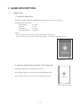
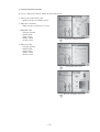
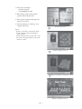
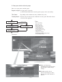
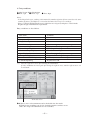
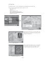
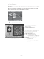
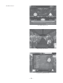
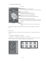
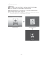
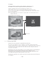
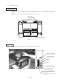
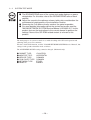
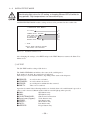
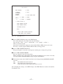
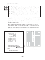
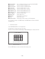
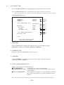
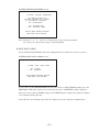
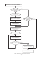
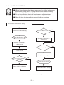
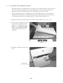
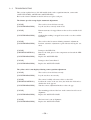
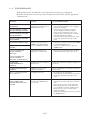
TABLE OF CONTENTS
BEFORE USING THE PRODUCT, BE SURE TO READ THE FOLLOWING:
TABLE OF CONTENTS
INTRODUCTION
1.GAME DESCRIPTION ....................................................................................................... 1
1−1 GAME FLOW ....................................................................................................... 1
1−2 TOURNAMENT MODE ....................................................................................... 22
1−3 SPECIAL FUNCTIONS ....................................................................................... 25
2.TEST MODE ...................................................................................................................... 26
2−1 SWITCH UNIT ..................................................................................................... 27
2−2 SYSTEM TEST MODE ........................................................................................ 29
2−3 GAME TEST MODE ............................................................................................ 30
2−4 GAME ASSIGNMENTS ....................................................................................... 32
2−5 MAIN TEST MODE .............................................................................................. 34
2−6 SATELLITE TEST MODE .................................................................................... 36
2−7 SYSTEM SETTING ............................................................................................. 48
3.CARD RECOGNITION FUNCTION AND ERROR DISPLAY ............................................ 52
3−1 CAMERA BASIC SETTING ................................................................................. 54
3−2 ADJUSTING THE CAMERA POSITION ............................................................. 56
3−3 TROUBLESHOOTING ........................................................................................ 59
3−4 ERROR MESSAGES .......................................................................................... 61
E0-0512
−i−
420-6716-08
INTRODUCTION
This manual provides information concerning the software operation of the product
"World Club Champion Football European Clubs 2004-2005" (hereinafter, "WCCF
2004-2005").
This manual is intended for the use of the owners, administrators, and operators of this
product. Read both this manual and the NAOMI NETWORK SYSTEM Service Manual
(No. 420-6660-01) carefully, and make sure you understand all pertinent points prior to
use.
This product uses an altered version of the NAOMI NETWORK SYSTEM. Due to this,
in the test mode for this system you will find a system test mode which allows all of the
functions that can be performed on any NAOMI game board product, such as automatic
self test and coin settings. Additionally, there is a game test mode which allows
functions specific to this game such as testing the input of specialized control devices.
This manual shall only detail specialized settings for the system test mode. For more
overall details on the system test mode, refer to the NAOMI NETWORK SYSTEM
Service Manual. However, all content referring to the NAOMI NETWORK SYSTEM
Service Manual GD-ROM is not required for this product.
Refer to the separate Owner's Manual for details of mechanical and hardware issues.
In the unlikely event that the product does not function correctly, DO NOT allow
anyone other than a technician to touch the internal system. Turn off the power to the
machine, making sure to unplug the electrical cord from the outlet, and contact the
office listed below or the point-of-purchase for this product.
Use of this product is unlikely to cause physical injuries or damage to property. However, points
that require special attention are indicated by thick underlining, the word "IMPORTANT" and
the symbol below.
Indicates important information that, if ignored, may result in the mishandling of
the product and cause faulty operation or damage to the product.
SEGA AMUSEMENTS EUROPE, LTD.
Suite 3a, Oaks House 12-22, West Street, Epsom, Surrey, KT18 7RG, United
Kingdom
Telephone: +44 (0) 1372 731820
e-mail: [email protected]
−ii−
Facsimile: +44 (0) 1372 731849
http://www.sega-amusements.co.uk
Definition of 'Site Maintenance Personnel or Other Qualified Individuals'
Procedures not described in this manual or marked as 'to be carried out by
site maintenance personnel or other qualified professionals' should not be
carried out by personnel without the necessary skill or technology. Work
carried out by unqualified persons may cause serious accidents, including
electrocution.
Parts replacement, maintenance inspections and troubleshooting should be carried out by site
maintenance personnel or other qualified professionals. This manual includes directions that
potentially dangerous procedures should only be carried out by professionals with the appropriate
specialized knowledge.
The site maintenance personnel or other qualified professionals mentioned in this manual are
defined as follows:
Site maintenance personnel:
Persons with experience in maintaining amusement equipment, vending machines, etc., working
under the supervision of the owner/operator of this product to maintain machines within
amusement facilities or similar premises by carrying out everyday procedures such as assembly,
maintenance inspections, and replacement of units/expendable parts.
Activities to be carried out by site maintenance personnel:
Amusement equipment/vending machine assembly, maintenance inspection and replacement of
units/expendable parts.
Other qualified professionals:
Persons employed by amusement equipment manufacturers, involved in design, production,
testing or maintenance of amusement equipment. Should have graduated from technical school or
hold similar qualifications in electrician/electronics/mechanical engineering.
Activities to be carried out by other qualified professionals:
Amusement equipment/vending machine assembly, repair/adjustment of electrical/electronic/
mechanical parts.
−iii−
BEFORE USING THE PRODUCT, BE SURE TO READ THE FOLLOWING:
To maintain safety:
To ensure the safe operation of this product, be sure to read the following before usage.
The following instructions are intended for the users, operators and the personnel in charge of the
operation of the product. After carefully reading and sufficiently understanding the warning
displays and cautions, handle the product appropriately. Be sure to keep this manual close to the
product or in a convenient place for future reference.
Herein, explanations which require special attention are enclosed with dual lines. Depending on
the potentially hazardous degrees, the terms of DANGER, WARNING, CAUTION, etc. are used.
Be sure to understand the contents of the displays before reading the text.
Indicates that mishandling the
product by disregarding this
pictograph will cause severe
injury or death.
Indicates that mishandling the
product by disregarding this
caution will cause a slight
hazardous situation which can
result in personal injury and/or
material damage.
Indicates that mishandling the
product by disregarding this
warning will cause a potentially
hazardous situation which can
result in death or serious injury.
For the safe usage of the product, the following pictographs are used:
Indicates "HANDLE WITH CARE." In order to protect the human body and
equipment, this display is attached to places where the Owner's Manual, Serviceman
Manual and/or Service Manual should be referred to.
Indicates a "Protective Earth Terminal." Before operating the equipment, be sure to
connect it to the Ground.
(The step may be omitted for products in which a power cord with earth is used.)
❍ Perform work in accordance with the instructions herein stated.
Instructions for work are explained by paying attention to the aspect of accident prevention.
Failing to perform work as per the instructions can cause accidents. In the case where only
those who have technical expertise should perform the work to avoid hazardous situation, the
instructions herein state that the site maintenance personnel should perform such work.
❍ Be sure to turn off the power before working on the machine.
To prevent an electric shock, be sure to turn off the power before carrying out any work that
requires direct contact with the interior of the product. If the work is to be performed in the
power-on status, the Instruction Manual herein always states to that effect.
❍ Be sure to ground the Earth Terminal.
(This is not required in the case where a power cord with earth is used.)
This product is equipped with the Earth Terminal. When installing the product, connect the
Earth Terminal to the "accurately grounded indoor earth terminal" by using an earth wire.
Unless the product is grounded appropriately, the user can be subject to an electric shock.
After performing repair, etc. for the control equipment, ensure that the Earth Wire is firmly
connected to the control equipment.
❍ Ensure that the Power Supply used is equipped with an Earth Leakage Breaker.
This product does not incorporate the Earth Leakage Breaker. Using a power supply which is
not equipped with the Earth Leakage Breaker can cause a fire when earth leakage occurs.
❍ Be sure to use fuses which meet the specified rating.
(Only for the machines which use fuses.)
Using fuses exceeding the specified rating can cause a fire and an electric shock.
❍ Specification changes (removal of equipment, conversion and addition) not
designated by SEGA are not allowed.
The parts of the product include warning labels for safety, covers for personal protection, etc.
It is very hazardous to operate the product by removing parts and/or modifying the circuits.
Should doors, lids and protective parts be damaged or lost, refrain from operating the product,
and contact where the product was purchased from or the office herein stated.
SEGA shall not be held responsible for any accidents, compensation for damage to a third
party, resulting from the specifications not designated by SEGA.
❍ Ensure that the product meets the requirements of appropriate Electrical
Specifications.
Before installing the product, check for Electrical Specifications. SEGA products have a
nameplate on which Electrical Specifications are described. Ensure that the product is
compatible with the power supply voltage and frequency requirements of the location. Using
any Electrical Specifications different from the designated Specifications can cause a fire and
an electric shock.
❍ Install and operate the product in places where appropriate lighting is
available, allowing warning labels to be clearly read.
To ensure safety for the customers, labels and printed instructions describing potentially
hazardous situations are applied to places where accidents can be caused. Ensure that where
the product is operated has sufficient lighting allowing the warnings to be read. If any label is
peeled off, apply it again immediately. Please place an order with where the product was
purchased from or the office herein stated.
❍ When handling the monitor, be very careful.
(Applies only to the product with a monitor.)
Some of the monitor (TV) parts are subject to high tension voltage. Even after turning off the
power, some portions are still subject to high tension voltage sometimes. Monitor repair and
replacement should be performed only by those technical personnel who have knowledge of
electricity and technical expertise.
❍ Be sure to adjust the monitor/projector properly.
(Applies only to the product with a monitor/projector.)
Do not operate the product leaving on-screen flickering or blurring as it is. Using the product
with the monitor/projector not properly adjusted may cause dizziness or a headache to an
operator, a player, or the customers.
❍ When transporting or reselling this product, be sure to attach this manual to
the product.
In the case where commercially available monitors and printers are used in this product, only
the contents relating to this product are explained herein. Some commercially available
equipment has functions and reactions not stated in this manual. Read this manual together
with the specific Instruction Manual of such equipment.
* Descriptions herein contained may be subject to improvement changes without notice.
* The contents described herein are fully prepared with due care. However, should any
question arise or errors be found, please contact SEGA.
INSPECTIONS IMMEDIATELY AFTER TRANSPORTING THE PRODUCT TO THE LOCATION
Normally, at the time of shipment, SEGA products are in a status allowing for usage immediately
after transporting to the location. Nevertheless, an irregular situation may occur during
transportation. Before turning on the power, check the following points to ensure that the product
has been transported in a satisfactory status.
❐ Are there any dented portions or defects (cuts, etc.) on the external surfaces of the cabinet?
❐ Are Casters and Adjusters damaged?
❐ Do the power supply voltage and frequency requirements meet with those of the location?
❐ Are all wiring connectors correctly and securely connected? Unless connected in the correct
way, connector connections can not be made accurately. Do not insert connectors forcibly.
❐ Do power cords have cuts and dents?
❐ Do the fuses used meet specified ratings? Is the Circuit Protector in an energized status?
❐ Are all accessories available?
❐ Can all Doors and Lids be opened with the Accessory Keys? Can Doors and Lids be firmly
closed?
1. GAME DESCRIPTION
1−1 GAME FLOW
1. Purchase a Starter Pack
The Starter Pack contains the minimum set of cards necessary to play the game.
Included in the starter pack:
Player Cards
IC Card
Card Sleeves
Game Instructions
11 cards
1 card
11 cards
1 manual
Notes:
- The IC Card is referred to as the "Club Team Card (Club Card)".
- An IC Card that was used with "WCCF 2002-2003" can also be used for this version.
Starter Pack
2. Choose a satellite station and insert a Club Team Card
The Club Team Card is a contract-less IC Card.
Data for up to 16 players can be stored on 1 Club Team Card.
Note: Do not remove the Club Team Card during gameplay.
IC Card (Club Team Card)
−1−
3. Register team manager
Before play begins, players must register a manager.
① Enter the manager's name
→ Enter a name (12 characters or
less).
② Enter the manager's date of birth
With these steps, manager registration is
complete.
Note: Once entered, manager data
cannot be changed.
Manager contract screen
Manager name entry screen
Manager D.O.B. entry screen
−2−
4. Create club team contract
To create a club team contract, follow the directions below.
① Choose the team's home town.
→ Pick from cities around the world.
② Enter the team name.
→ Enter a name (12 characters or less).
③ Edit Home Kit
→ Design (pattern)
→ Main colour
→ Trim colour
→ Shorts colour
→ Socks colour
Hometown selection screen
④ Edit Away Kit
→ Design (pattern)
→ Main colour
→ Trim colour
→ Shorts colour
→ Socks colour
Team name entry screen
Home & Away Kits edit screen
−3−
⑤ Select the team badge.
→ Design (pattern)
→ Crown/ribbon Yes/No
⑥ Place Player Cards on the pitch to
register them with the team.
⑦ The registered players will appear in
the kit you created.
⑧ Now the manager is in charge of an
original club team.
Select badge screen
Notes:
- If there is already a team on the Club
Team Card, the game will skip this
contract mode.
- If only manager data exists on the card,
the game will begin from the club team
contract section.
Player registration screen
Player registration confirmation screen
Manager assignment screen
−4−
5. Enter game with the following steps
There are league games and title games.
Regular League: A league game (7 in total).
(1st Division/2nd Division) A match against a player of the same ability.
Title Game:
Depending on the tournament, entry conditions may exist.
Friendly Match: For those who do not meet the conditions for a title game. This mode allows
selection of the opponent.
Regular League
Cannot enter
Titles:
Upon defeat
Title Game
Friendly Match
Regular League
<CFB Main>
- Pre-season Cup
- Enterprise Cup
- King's Club Cup
- Title Holder's Cup
- Continental Cup
- National Super Cup
- Continental Super Cup
- Japan Trophy
- Champion's Trophy
- International Club Championship
- U-5R Championship
◆ With each Title Game
(including the Regular League),
the manager's worth (salary)
changes.
◆ Friendly matches do not
increase the manager's salary,
but gives the team a chance to
practice.
−5−
6. Entry conditions
Regular League Point Calculations
● Win: 3 pts ● Draw: 1 pt ● Loss: 0 pts
Notes:
- In the Regular League, ranking is determined by number of points. If two teams have the same
number of points, goal difference is used to determine their respective rankings.
- Places 7 and 8 in the Regular League 1st Division are relegated, and places 1 and 2 in the
Regular League 2nd Division are promoted.
Entry conditions are listed below.
Title Name
Pre-season Cup
Enterprise Cup
King's Club Cup
Title Holder's Cup
Continental Cup (*)
National Super Cup (*)
Continental Super Cup (*)
Japan Trophy (*)
Champion's Trophy (*)
International Club Championship
U-5R Championship
Condition
None
None
None
None
Higher than 6th in Regular League 1st Division
Won King's Club Cup
Won Continental Cup
Won Champion's Trophy
Higher than 4th in Regular League 1st Division
1 billion yen or more in earnings
Regulations U-5R
(*): Lose the right to re-enter after winning the tournament.
If entry conditions are met again after losing the right to enter, another right to enter can
be obtained.
Team data screen
◆ Rights to enter each tournament can be checked before the match.
Regular League standings can also be checked from the team data screen.
(Note: The 2 top-left tournaments are not available.)
−6−
7. Team Management
Team management provides understanding of the team's current condition and allows training to
be carried out.
Team management screen
Management menu screen
(1) Training
Team parameters can be raised through training, improving the ability of the team as a
whole.
(2) Communication
By meeting with the players face-to-face, it is possible to increase their motivation and
improve communication, and set the position in the game or change a player's number.
(3) Team Data
This mode allows you to see an overall snapshot of your team's condition.
See record of earnings, win/loss record, titles won, etc.
View team consensus, player and manager data, or retire a manager.
(4) Player Registration
Change the registered players.
Championship Won event
−7−
(1) Training
It is possible to create many different teams from the same basic data, depending on the training
you carry out.
The types of training and the parameters that increase are shown below.
Attack
Defence
Passing
Possession
Speed
Power
Training Match
Day Off
Increase attacking skill
Increase defensive skill
Improve possession time
Increase effectiveness of tackles
Increase speed
Increase power
Improve teamwork
Increase motivation
Note: Special training menus are
unlocked when certain
conditions are met.
Formation check screen
After selecting "Training", first adjust team formation
and strategy settings.
Practice menu screen
After completing the training session, the
corresponding parameters increase. The
amount the parameters increase is random, but decreases with repetition of the
same type of training, and also depends
on the manager's abilities.
−8−
Practice screen
(2) Communication
Communicate with players.
● Talk to one player.
Talk one-on-one with a player to increase
his motivation.
● Talk to two players.
Talk to two players at the same time to
improve their partnership.
● Set positions.
Designate a captain, free-kick, corner kick,
or penalty kicker.
● Change a player's shirt number.
A jersey number can be changed freely.
Note that bad advice may have a negative effect
on a player's morale.
Communication selection screen
Talk to two players
Talk to one player
Select a total of 3 players to talk to.
Designate position
Change a player's shirt number
−9−
(3) Team Data
Team data provides a variety of information concerning the status of the team.
You can view the following data on the team data screen.
- Prize money won
- Record
- Record winning streak
- Titles won and entry qualifications
- Current division in the Regular League
- Regular League data
Team data screen
On the player data screen, you can not only view
individual player data but also check the position
assigned to each player.
Player data screen
On the teamwork checkup screen, you can check
the individual teamwork of each player and the
overalls teamwork status of the entire team.
Teamwork checkup screen
− 10 −
On the manager data screen you can view manager
data and total records, as well as changes in
Regular League results. You can also retire a
manager.
Manager data screen
A Club Team Card on which the manager has
retired cannot be played.
By using it in conjunction with a new Club Team
Card, it is possible to carry over the old manager's
abilities.
Manager retirement screen
When playing a friendly match, it is possible to
request a game with a specific opponent.
Match request screen
Requests for matches from other teams can be
checked in real time.
Management menu screen
Playing friendly matches will help to increase
teamwork between your players.
− 11 −
(4) Player Registration
Up to 16 players can be registered per club team, and once registered, players will grow together
as a team.
If a player's registration is erased and the player later rejoins the team, the data is lost and the
player is treated as if they just joined the team for the first time.
Current team parameters and tactics.
The player registration screen shows players'
communication abilities.
The thicker the line between two players,
the better their communication.
Match regulations can also be checked from this screen.
Regulations are restrictions on the Player Cards
when used in Tournament mode.
The following five types exist.
● FREE: All Player Cards can be used.
● U-5R: Up to 5 Rare Cards may be used.
(The rest must be Special or Regular Cards)
● U-5:
Up to 5 Special or Rare Cards may be used.
(The rest must be Regular Cards)
● REGULAR:
Regular Cards only.
● TOTAL POINTS:
The total points on the registered players'
parameters.
Player registration screen
− 12 −
8. Setting Tactics
When taking part in the U-5R Championship, player registration becomes "Set tactics."
Player registration thus cannot be altered. Only the formation and tactics of the registered
champion team can be altered.
Set tactics screen
− 13 −
9. Before the game starts
The match and team data will be displayed on the CFB main screen and satellite screen
immediately before the start of a match.
<CFB main screen>
Schedule display screen
Prior to the start of a match screen
− 14 −
<Satellite monitor>
Pre-match demo screen
Player entry scene screen
Formation introduction screen
− 15 −
10. Gameplay
During gameplay, the following three actions may be performed.
① Change the formation on the pitch.
● Data is instantly read from the cards on the
pitch.
● Change team formation depending on game
conditions and strategies learned in training.
● As long as the corresponding cards are placed
on the pitch, any formation can be read, so the
player can create formations freely.
● To substitute players, simply exchange cards
from the sub area and the field area. Just as in
real football, substitutions can only be made
while the ball is out of play, so it is wise to
substitute tired players at half-time.
Satellite screen: Game in progress
② Shoot using the Action Buttons.
● The essence of football.
Press the Shoot button and your players will react instantly. Use it when a player is close to
the goal and try to score!
● The goalkeeper; the last line of defense, can also be controlled directly by the user.
When the Keeper button is held down, the keeper rushes in the direction of the ball. Time the
button push carefully for a great save!
③ Select tactics.
Use this button to select tactics to fit the conditions.
Note: Press the START button during a match to switch between vertical and horizontal screen
display. Press the DATA button to switch display of team parameters ON or OFF.
PITCH
ACTION
BUTTON
TACTICS
SELECT
CONTROL PANEL
− 16 −
11. Team grid and position radar
① Team grid
● Playing Style
Displays the current team playing style.
This is calculated based on the shape of the formation graph.
● Playing Style Ranking
Ranking of functionality of team style.
Determined by growth on the training graph.
● Training Level (yellow part of the graph)
Shows increase in total team ability through training.
● Formation Level (blue part of the graph)
The sum of the individual abilities of all players on the pitch.
The shape of the map depends greatly on positions assigned
to players.
Team grid
● Morale
A representation of the team's desire to win when they are
behind.
The larger the training map and formation map overlap portion, the higher the team's ability
level.
② Position radar
Current card positions are shown on the radar, and the radar screen is updated when cards are
moved.
The positions are separated based on colour.
Red: FW Orange: MF Green: DF Blue: GK
Furthermore, the position radar displays the player's current status as well as their motivation.
The coloured gauge on the position radar displays their remaining energy.
Radar icon
Position radar
− 17 −
12. From half-time to game results
<From half-time to final results>
Half-time screen
Game results
Friendly Match
Earnings screen
Salary change screen
Friendly match result
screen
Prize Money screen
Continue screen
GAME OVER screen
− 18 −
Title Match
(Regular League)
① Half-time
Games are separated into two halves with a half-time period in-between and a change of sides
after.
Player substitution can only occur while play has stopped.
Due to the brief match time, it is possible to finish a match without having any opportunities to
substitute at all. Therefore, it is recommended that any substitutions be made at half-time.
② Game results
Final score, scorers, shots, and possession ratios are displayed.
③ Change in manager's salary is displayed (except in Friendly Matches).
④ For Friendly Matches, the effects of training are shown.
− 19 −
13. Other screens
① Replay
Watch goal and offside replay scenes from various angles.
② Victory Clip
After a Title Match victory, the winning team is feted.
③ Warning
In some cases, warning messages may be displayed.
− 20 −
14. Saving game results
After a game finishes, team improvement and game results are saved
to the Club Team Card for the next time.
The card can only hold up to 16 players in memory.
Even after a manager retires, the manager's abilities and data can be
transferred.
IC Card (Club Team Card)
Each time a game ends, a Player Card is dispensed from the machine.
The Player Card is wrapped so that its contents are secret until opened.
The new card is selected at random and has no connection to the user's performance, etc.
Whether the new player card is added to the team or not is entirely up to the user.
New card screen
Wrapped Player Card
− 21 −
1−2 TOURNAMENT MODE
In Tournament Mode, the operator can create a tournament to suit their needs/location.
A schedule of matches can be programmed to fit the scale of the tournament and number of
users participating.
1. Regulations
Regulations (limits on the type of Player Cards allowed) can also be set in Tournament Mode.
There are five types of regulations, which must be set in Test Mode before a tournament
commences.
● FREE:
● U-5R:
● U-5:
All Player Cards may be used.
Only teams with less than a total of 5 Rare Cards may participate.
Only teams with less than a total of 5 Rare and Special Cards may
participate.
● REGULAR:
Only teams comprised entirely of Regular Cards may participate.
● TOTAL POINTS: Set an upper limit for the total points of Player Cards.
Note: If the Player Cards that have been placed on the pitch do not meet the regulations, the
game will not proceed to the next sequence (includes instances when time runs out).
2. Club Team Card
In Tournament Mode, Club Team Cards with expired manager contracts can be used. The
appropriate settings must be made in Test Mode.
● In Tournament Mode, no data is saved to the Club Team Card.
● In Tournament Mode, manager abilities cannot be transferred.
● It is possible to use new Club Team Cards, but only manager
registration and manager contract registration is saved. Game results
and training results are not saved. Manager terms may not be
shortened.
− 22 −
3. Tournament Type
The tournament type in tournament mode can be set in Test Mode.
There are 9 different tournament types available:
Tournament Format
Tournament
Tournament
Home & Away Leg Tournament
Home & Away Leg Tournament
Group Stage
Group Stage and Knockout
Title Match
Neighbour Match
Neighbour Match/PK
Teams
8 Teams
4 Teams
8 Teams
4 Teams
8 Teams
8 Teams
2 Teams
8 Teams
8 Teams
Games
3 Games
2 Games
5 Games
3 Games
3 Games
5 Games
1 Game
1 Game
1 Game
The above 9 types of tournament may be held in any order that you desire.
<Satellite-based opponent selection>
● In a Neighbour Match tournament, opponents are chosen using the following system.
(In all other games the selection is random.)
1 VS 2 3 VS 4
5 VS 6 7 VS 8
● For tournaments with fewer than eight teams, the following satellites are used.
For 2 teams: 1, 2
For 4 teams: 1 - 4
Note the satellite designations and settings in Test Mode.
− 23 −
4. Starting a tournament
In Tournament Mode, when the card placement is complete for every satellite, the next
sequence begins.
If there is a vacant seat, the sequence cannot be carried out. In such cases, press the Shoot
Button at the advertising screen to display the non-participation screen.
At the non-participation screen, if "do not participate" is selected, the satellite will produce a
CPU team and the following sequence can proceed.
Note: The satellite with the CPU team will display a standby screen, and the satellite cannot be
used until the tournament (in a 1 tournament setting) finishes.
Non-participation screen
Advertising screen
Standby screen
− 24 −
5. Continue
In Tournament Mode, any losing satellites will display a Game Over screen.
The standby screen will then be displayed until the tournament finishes.
Satellites continuing to the next game will display the continue screen.
At the continue screen, if "Yes" is selected, the satellite proceeds to the next game.
If "No" is selected, the standby screen is displayed and the CPU takes control of that team for
the rest of the tournament.
Note: At the continue screen, there must be a response from every terminal before the next
sequence will occur.
After a loss/at the end of a tournament:
Game Over
Standby screen
When continuing:
No
Yes
Next Game
Continue
1−3 SPECIAL FUNCTIONS
Automatic data restore function for corrupt Club Team (IC) Cards
If for some reason a R/W error occurs, resulting in a read failure and IC Card data being
corrupted ("Club Card data is corrupt" is displayed), there is a function that will recover IC Card
data when the game is played again on the same cabinet. Note that corrupt data cannot be
restored in every incidence.
This function restores data corrupted during a read error during gameplay or when updating an
IC Card. Therefore, IC Cards corrupted outside the premises cannot be restored.
This function restores data which was successfully read when starting a game and any data
successfully backed-up in the cabinet just before an error occurs.
This function is applicable to any satellite connected to the cabinet at the time the IC Card data
was corrupted.
− 25 −
2. TEST MODE
● Operation of test mode for the 2 game boards inside the main unit
should be performed by the site maintenance personnel or other
qualified professionals.
This task involves working inside the cabinet while the power is on and
operating the small buttons at the front of the game boards.
If the work is performed by a person without the necessary knowledge
and skills, electric shock or other serious accidents may occur.
● During operation of test mode for the game boards inside the main
unit, nothing inside the unit should be touched except the small buttons
at the front of the game boards. Otherwise, electric shock, short circuit
or other accidents may result.
Be careful not to trap fingers when opening, closing, installing or removing
doors/lids, etc.
● After changing settings, exit test mode by selecting EXIT on the menu
screen. Any changes to settings will be invalid if test mode is not exited
properly.
● The left and right speakers of the main unit always play sound during
advertising, even if the setting is changed to OFF in test mode.
● Any error in the communication settings will render play impossible.
● Test mode for the game boards inside the main unit is necessary only
during setup.
− 26 −
2−1 SWITCH UNIT
CFB Main Unit
To gain access to the sound volume, unlock the SW door at the front of the CFB main unit and
open.
Adjust the sound volume for the left and right fence speakers.
SPEAKERS
SOUND VOLUME
SW DOOR
FIG. 2. 1 a
Satellite
Unlock side cover R and open. A switch unit is located inside.
DEGAUSS BUTTON
SOUND VOLUME
SW 1
SW 2
SERVICE BUTTON
TEST BUTTON
PHOTO 2. 1
MONITOR ADJUSTMENT PANEL
(See Section 15.)
FIG. 2. 1 b
− 27 −
● SW 1:
Use to clear errors. (See 3-4.)
Press during the error screen to display the screen for issuing cards.
SW1 is also used to reset the number of Player Cards to be issued back to 0.
Hold down for 3 seconds or more to eject the IC card in an emergency.
If Player Cards are not being recognized due to camera trouble, continuing to play will cause
further trouble, such as resetting of player records, when saving is performed. Saving can be
avoided by forcibly ejecting the IC Card.
In this case, a failure is automatically recorded on the card.
● SW 2:
Not used.
● SERVICE Button (SERVICE):
Use to enter service credits.
Credits are entered but not counted on the coin metre.
Use as a selection button in test mode.
● TEST Button (TEST):
Use to enter test mode.
Use as a confirmation button in test mode.
● Sound Volume (SOUND VOLUME):
Use to adjust the volume of the left and right speakers on the satellite monitor.
● Degauss Button (DEMAG) :
Use to remove screen color irregularities due to CRT magnetization.
Press this button before adjusting the monitor colour.
− 28 −
2−2 SYSTEM TEST MODE
● The BOOKKEEPING area of the system test mode displays no gamerelated data. For this data, refer to the BOOKKEEPING area of each
satellite.
● Adjust the sound to the optimum volume, taking into consideration the
environmental requirements of the installation location.
● Removing the Coin Metre circuitry renders the game inoperable.
● For more detailed information about the system test mode, read the
"NAOMI NETWORK SYSTEM Service Manual (420-6660-01)" for this
product, but use the instructions in the current manual to perform the
settings. None of the GD-ROM related content is relevant to this
product.
The main purpose of system test mode is to enable checking of the IC board operation and
adjusting of the projector or monitor.
For more detailed information, read the "NAOMI NETWORK SYSTEM Service Manual", but
settings for the product should be made as follows.
The ADVERTISE SOUND setting cannot be changed. (Main unit only)
● CABINET TYPE:
● MONITOR TYPE:
● SERVICE TYPE:
● COIN CHUTE TYPE:
● NETWORK TYPE:
● REMOTE:
1PLAYER(S)
HORIZONTAL
COMMON
COMMON
ETHER
ENABLE
− 29 −
2−3 GAME TEST MODE
Test mode for the game boards inside the main unit is necessary only
during setup.
Running test mode for the game boards inside the main unit is only necessary when adjusting
the projector during positioning and setup or in the event of trouble requiring game board
replacement.
The following procedure for main unit test mode provides a functional description but the
process should only be carried out by the site maintenance personnel or other qualified
professionals.
To test the main unit, put both sides into test mode at the same time.
If only one side of the main unit is put into test mode, the other side will display an error screen.
This is not a malfunction. (See 3-4.)
Select GAME TEST MODE from the System Menu screen to display the Game Test Menu
screen.
Use the SERVICE Button to move the cursor to the desired test item, and press the TEST
Button to select.
For the selected item, read the explanations below regarding operation.
The screen content will vary according to the main unit and satellite settings.
− 30 −
Game Test Mode Screen
For main settings using GAME ASSIGNMENTS:
<<GAMETESTMODE>>
GAMEASSIGNMENTS
2−4
MAINTEST
2−5
SYSTEMSETTING
2−7
->EXIT
SELECTWITHSERVICEBUTTON
ANDPRESSTESTBUTTON
FIG. 2. 3 a Game Test Menu screen (Main Unit)
After the test is complete, move the cursor to EXIT and press the TEST Button to return to the
System Menu screen.
For satellite settings using GAME ASSIGNMENTS:
<<GAMETESTMODE>>
GAMEASSIGNMENTS
2−4
SATELLITETEST
2−6
SYSTEMSETTING
2−7
->EXIT
SELECTWITHSERVICEBUTTON
ANDPRESSTESTBUTTON
FIG. 2. 3 b Game Test Menu screen (Satellite)
After the test is complete, move the cursor to EXIT and press the TEST Button to return to the
System Menu screen.
− 31 −
2−4 GAME ASSIGNMENTS
The screen will not reflect the actual satellite layout if satellites are
positioned in any pattern other than those indicated by SEGA, or if there is
an error in the satellite number/distribution/location settings. Be sure these
settings are correct.
Select GAME ASSIGNMENTS to set the placement of the main units and satellites.
The display of the number of satellites will change when SATELLITE TOTAL is selected.
Set the actual number of satellites and the display of the number of satellites to be the same.
Note: With two satellites, use the setting for four satellites.
Select NUMBER DISPLAY to switch the Satellite number display ON/OFF.
<<GAMEASSIGNMENTS>>
SATELLITETOTAL
-8NUMBERDISPLAY
ON
1234
ARRANGEMENT
POSITION
5678
->EXIT
SELECTWITHSERVICEBUTTON
ANDPRESSTESTBUTTON
FIG. 2. 4 a GAME ASSIGNMENTS screen
Use the ARRANGEMENT selection to change the displayed satellite positioning.
Set the screen so that the displayed satellite positioning reflects the actual pattern being used.
An error screen will be displayed if a different positioning pattern is set. In this case, reset the
displayed satellite positioning to the correct pattern.
Select POSITION to change the location of satellites on the positioning display.
Set so that the satellite (main) positioning locations and the displayed locations are the same.
Any duplication in satellite positioning will result in an error screen.
Reset the displayed satellite positioning to the correct pattern if an error screen is displayed.
It will not be possible to return to the Game Play screen if the satellite has been used to perform
the main settings.
− 32 −
Satellite Positioning Patterns
8 Satellites
A
B
C
D
6 Satellites
E
F
4 Satellites
G
2 Satellites
H
I
Note: For two satellites, set the front two of
the 4 satellites (H).
FIG. 2. 4 b
After changing the settings, select EXIT and press the TEST Button to return to the Game Test
Menu screen.
− 33 −
2−5 MAIN TEST MODE
In main test mode, it is possible to test and change settings for the main unit.
If only one side of the main projection unit is put into test mode, the other side will display an
error screen, so that side should also be put into test mode.
<<MAINTESTMODE>>
OUTPUTTEST
①
DLPCOLORTEST
②
SYNCHRONOUSTEST
③
->EXIT
SELECTWITHSERVICEBUTTON
ANDPRESSTESTBUTTON
FIG. 2. 5 a Main Test Menu screen
After changing the settings, select EXIT and press the TEST Button to return to the Game Test
Menu screen.
① OUTPUT TEST
The output test enables testing of the lighting illumination.
The marker display shifts automatically when the output test is selected and normal LED
operation is confirmed when the (LED) row illuminates.
Only the left-hand main monitor (projector) can be used for output testing.
<<OUTPUTTEST>>
□□□□□□□□□□
PRESSTESTBUTTONTOEXIT
FIG. 2. 5 b OUTPUT TEST screen
After changing the settings, select EXIT and press the TEST Button to return to the Main Test
Menu screen.
− 34 −
② DLP COLOR TEST
Select DLP COLOR TEST to display the adjustment screen for the main unit monitors
(projectors).
On selection of DLP COLOR TEST, the entire screen is displayed white.
Press the TEST Button to display white-to-black gradation on the entire screen.
Press the TEST Button again to return to the Main Test Menu screen.
Adjust so that the colors of the left and right projectors are the same.
Read the Owner's Manual Section 14 for details of the adjustment procedure.
③ SYNCHRONOUS TEST
The SYNCHRONOUS TEST enables checking of the synchronization of the main unit monitors
(projectors).
This test requires both sides to be in test mode. Operation is normal if the "CHECKING"
indication is followed by "SYNCHRONOUS OK."
The following describe sources of error indication.
For the following error indications, check for any disconnection of serial cables linking to the
NAOMI 2 board inside the main unit or other connection faults.
● "SERIAL COMMUNICATION ERROR"
Serial cable disconnection or other connection faults are likely causes.
● "SYNCHRONOUS ERROR"
Serial cable disconnection, a board problem or a chip problem are likely causes.
<<SYNCHRONOUSTEST>>
SYNCHRONOUSOK
PRESSTESTBUTTONTOEXIT
FIG. 2. 5 c SYNCHRONOUS TEST screen
After changing the settings, select EXIT and press the TEST Button to return to the Main Test
Menu screen.
− 35 −
2−6 SATELLITE TEST MODE
Avoid using light colors for I/O testing, or keeping Winner LEDs lit white for
long periods. High temperatures can cause burn injury.
SATELLITE TEST MODE enables settings and tests to be performed on the satellite side.
<<SATELLITETESTMODE>>
I/OTEST
①
CAMERABASICSETTING
CARDREADTEST
ICCARDTEST
BOOKKEEPING
BACKUPDATACLEAR
②
③
④
⑤
⑥
->EXIT
SELECTWITHSERVICEBUTTON
ANDPRESSTESTBUTTON
FIG. 2. 6 a Satellite Test Menu screen
After changing the settings, select EXIT and press the TEST Button to return to the Game Test
Menu screen.
① I/O TEST
The I/O TEST enables testing of I/O devices.
The CARD VENDOR item indicates the status of the card dispenser.
If the marker is checked, the status below is indicated.
There may be several checked markers, depending on the status of the dispenser.
● SENSOR:
● STANDBY:
● ERROR:
● EMPTY:
A card is in the card outlet.
A card is about to be issued.
A card dispenser malfunction has occurred.
There are no cards left.
Operation is normal if the following markers are checked when each switch button is pressed or
when a card is inserted. (Buttons marked with an asterisk light up when pressed.)
● SW1:
SW1 button entry
● SW2:
SW2 button entry
● CLUB TEAM CARD:
Club Team Card insertion
● Cross icons (5 types)*:
Tactic buttons entry
● START:
Start button entry
● SHOOT*:
Shoot button entry
● DATA :
Data button entry
● KEEPER*:
Keeper button entry
− 36 −
<<I/OTEST>>
CARDVENDOR□SW1
□SENSOR□SW2
□STANDBY
□ERROR
□EMPTY□CLUBTEAMCARD
□□START□DATA
□□□
□□SHOOT□KEEPER
->LIGHTCOLOR□
CARDVENDORPAYOUT
CARDVENDORRESET
SOLENOIDON/OFF
EXIT
SELECTWITHSERVICEBUTTON
ANDPRESSTESTBUTTON
FIG. 2. 6 b I/O TEST screen
● Select LIGHT COLOR and press the TEST Button.
The colour displayed to the right of the item will change.
Gray (not lit) → blue → green → marine blue → red → purple → yellow →
white (8 selections in all)
Operation is normal if the displayed colour and the Winner LED colour are the same.
For safety, avoid keeping the Winner LED lit white for long periods.
● Select CARD VENDOR PAYOUT.
The payout signal is sent to the card dispenser and the player card pack is paid out.
● Select CARD VENDOR RESET.
The reset signal is sent to the card vendor.
When card jams occur, cards can be issued and the card dispenser error can be cleared by
selecting CARD VENDOR RESET and pressing the TEST Button.
● The insertion status of the Club Team Card can be changed using SOLENOID ON/OFF
selection.
ON:
The Club Team Card is inserted.
OFF:
The Club Team Card has been ejected.
(If already inserted, the Club Team Card is ejected.)
After changing the settings, select EXIT and press the TEST Button to return to the Satellite
Test Menu screen.
− 37 −
② CAMERA BASIC SETTING
● When laying the test sheet down, make sure it is neither in the wrong
position nor wrong side up, is lying flat and is not folded or drifting
above the field surface.
● Do not move the test sheet until basic camera adjustments are
completed.
● The adjustments made on this screen involve no adaptation to ambient
light conditions.
● The test sheet is used for periodic inspections. Store it carefully to
prevent creasing.
It is possible to make camera adjustments for each component by selecting CAMERA BASIC
SETTING.
Always make such adjustments after replacing the ASSY CCD CASE (camera unit) or ASSY
LED L/R (LED unit).
Use the same procedures whenever readjustment is necessary after moving components or
checking the adjustment status.
Before executing Camera Basic Setting, lay the test sheet print correctly on the field sheet,
pattern side down, with the " ◎ " mark in the center and the " ○ " mark on the monitor side.
At this point, perform adjustments or remedial actions to ensure that all settings are correct.
If "NG" is displayed, check for connection faults or hardware damage.
Read Section 3 for details of adjustment procedures.
<<CAMERABASICSETTING>>
CommunicationOK
BootVersion1.000
BootChecksumOK
XXXXXXXX
ProgVersionXXXX
ProgChecksumOK
XXXXXXXX
IC3MemoryTestOK
IC4MemoryTestOK
CCDRegisterOK
ShutterTimeXXXX
BrightnessXXX
FocusXXX
CameraPositionOK
LIGHTBALANCE
CAMERAPOSITIONSETTING
CAMERASHUTTERAUTOSETTING
CAMERASHUTTERSAVE
Ⅰ
Ⅱ
Ⅲ
Ⅳ
->EXIT
SELECTWITHSERVICEBUTTON
ANDPRESSTESTBUTTON
FIG. 2. 6 c CAMERA BASIC SETTING csreen
− 38 −
↓
MONITOR SIDE
FIG. 2. 6 d Test Sheet
● Communication:
State of communications between camera board and NAOMI 2
● Boot Version:
Camera board IC18 boot ROM version
● Boot Checksum:
Camera board IC18 boot ROM checksum
● Prog Version:
Camera board IC18 firmware version
● Prog Checksum:
Camera board IC18 firmware checksum
● IC3 Memory Test:
Camera board IC3 (RAM) operation test
● IC4 Memory Test:
Camera board IC4 (RAM) operation test
● CCD Register:
Camera board CCD setting
● Shutter Time:
Camera shutter speed
● Brightness:
Mean brightness of shot images
● Focus:
Camera focus (value)
● Camera Position:
Focal position of camera relative to field (components)
After changing the settings, select EXIT and press the TEST Button to return to the Satellite
Test Menu screen.
Ⅰ.LIGHT BALANCE
Select LIGHT BALANCE to view the light balance.
The light balance is normal if all edges fade to white.
Any areas of excessive black are from damage to ASSY LED L/R parts or faulty connections.
<<LIGHTBALANCE>>
PRESSTESTBUTTONTOEXIT
FIG. 2. 6 Ⅰ LIGHT BALANCE screen
Press the TEST Button to return to the Camera Basic Setting screen.
− 39 −
Ⅱ.CAMERA POSITION SETTING
Select CAMERA POSITION SETTING to display a screen for checking the focal position of
the camera.
If the green cross mark (indicating the focal point of the camera) is not inside the yellow circle
(indicating the center of the field), the indication to the right of Camera Position will be "NG."
Adjust the position of the camera as necessary.
Read Section 3 for details on the adjustment procedures.
<<CAMERAPOSITIONSETTING>>
CameraPositionOK
ShutterTimeXXXX
BrightnessXXX
FocusXXX
PRESSTESTBUTTONTOEXIT
FIG. 2. 6 Ⅱ CAMERA POSITION SETTING screen
Press the TEST Button to return to the Camera Basic Setting screen.
− 40 −
Ⅲ.CAMERA SHUTTER AUTO SETTING
Exiting the Camera Basic Setting screen without saving the newly set
shutter speed value will cause reversion to the previous value.
To save the newly set value, always carry out the procedures in the next
section, "IV. CAMERA SHUTTER SAVE."
CAMERA SHUTTER AUTO SETTING enables automatic shutter speed adjustment. The
shutter speed best-suited to each component is automatically detected and set.
<<CAMERASHUTTERAUTOSETTING>>
CurrentShutterTimeXXXX
NewShutterTimeXXXX
NOWSHUTTERSETTING...
-> RESTART
STOP
EXIT
SELECTWITHSERVICEBUTTON
ANDPRESSTESTBUTTON
FIG. 2. 6 Ⅲ CAMERA SHUTTER AUTO SETTING screen
● Current Shutter Time: Shutter speed currently saved on the camera board.
● New Shutter Time:
Setting value calculated by automatic adjustment.
● Select RESTART to repeat the automatic shutter speed setting procedure.
● Select STOP to cancel execution of the automatic setting procedure.
After changing the settings, select EXIT and press the TEST Button to return to the Camera
Basic Setting screen.
− 41 −
Ⅳ.CAMERA SHUTTER SAVE
● During play, the camera will operate at the shutter speed saved on this
screen. Not saving an appropriate setting may render card recognition
impossible.
● Turning off the power during the save operation will render correct
saving of the setting impossible. Never turn off the power during the
save operation.
Select CAMERA SHUTTER SAVE to save the shutter speed.
<<CAMERASHUTTERSAVE>>
CurrentShutterTime6200
NewShutterTime7000
YES(SAVE)
->NO(CANCEL)
SELECTWITHSERVICEBUTTON
ANDPRESSTESTBUTTON
FIG. 2. 6 Ⅳ CAMERA SHUTTER SAVE screen
To save, use the SERVICE Button to position the cursor over "YES (SAVE)" and press the
TEST Button. The setting is saved and the display returns to the Camera Basic Setting screen.
Alternatively, position the cursor over "NO (CANCEL)" and press the TEST Button. The
setting is not saved and the display returns to the Camera Basic Setting screen.
− 42 −
③ CARD READ TEST
● Do not use bent or dirty test cards.
● A total of 16 test cards should be distributed uniformly on the field
sheet. Make sure the cards are positioned correctly and pointing in the
right direction.
● Do not move the test cards until the recognition process is finished.
● Store test cards with care so they do not get creased.
● Do not use cards other than the test cards or place more than 17 test
cards on the field sheet or testing may be impossible.
Select CARD READ TEST to perform the card read (recognition) test.
Use test cards for the card read test.
Before testing, arrange 16 test cards (in 4 rows x 4 columns) uniformly on the field sheet
(without laying the test sheet), including the corner and GK (goalkeeper) positions.
There are 23 test cards, but only 16 are actually used for testing. Keep the remaining cards as
spares.
<<CARDREADTEST>>
->CARDREADCHECK
EXIT
SELECTWITHSERVICEBUTTON
ANDPRESSTESTBUTTON
FIG. 2. 6 e CARD READ TEST screen
FIG. 2. 6 f Test Card positioning
After changing the settings, select EXIT and press the TEST Button to return to the Satellite
Test Menu screen.
TEST CARD
601-11155
FIG. 2. 6 g
− 43 −
Select CARD READ CHECK to execute. "NOW CHECKING...**%" is displayed during the
card read check, and the positioned cards appear on the right of the screen.
The read check has ended when "CHECK FINISHED" is displayed.
Operation is normal if "OK" is indicated for all cards.
Card reading is unstable if there is no card indication or if "NG" is displayed. (See below.)
<<CARDREADCHECK>>
NOWCHECKING...
0%
->RESTARTCHECK
OK
OK
OK
OK
OK
OK
OK
OK
OK
OK
OK
OK
OK
OK
EXIT
SELECTWITHSERVICEBUTTON
ANDPRESSTESTBUTTON
OK
OK
FIG. 2. 6 g CARD READ CHECK screen
Select RESTART CHECK to redo the card read check.
After changing the settings, select EXIT and press the TEST Button to return to the Card Read
Test screen.
The probable causes of no card indication or display of "NG" are given below.
Clear the problem using the countermeasures below, and again check the card recognition
function.
TABLE 2. 6
CAUSE
COUNTERMEASURE
Camera position is off-center.
Adjust position. <See 3-2>
Shutter speed setting is faulty.
Adjust shutter speed. <See 2-6, ② , Ⅲ & Ⅳ .>
ASSY LED L/R is damaged.
Replace ASSY LED L/R. <See the Owner's Manual 16-2>
Field glass/sheet is dirty.
Clean. <See the Owner's Manual Section 17>
Replace. <See the Owner's Manual Section 18>
Mirror is dirty.
Clean. <See the Owner's Manual Section 17>
− 44 −
④ IC CARD TEST
The IC CARD TEST enables read check of the IC cards.
Select IC CARD TEST. The IC Card Test screen is displayed.
After the Club Team Card has been inserted, "CHECKING NOW..." is displayed, and checking
begins automatically.
"IC CARD TEST OK" indicates normal operation.
The Club Team Card is ejected automatically.
If "R/W ERROR OR INSERTED CARD IS INVALID" is displayed, the wrong card has been
inserted or the IC card reader/writer is damaged.
If "IC CARD R/W HAS FAILED" is displayed, the card reader/writer has a faulty connection or
similar problem.
<<ICCARDTEST>>
INSERTCLUBTEAMCARD
PRESSTESTBUTTONTOEXIT
FIG. 2. 6 h IC CARD TEST screen
Press the TEST Button to return to the Satellite Test Menu screen.
− 45 −
⑤ BOOKKEEPING
Select BOOKKEEPING to display the following three operating data screens.
BOOKKEEPING1/3
NUMBEROFGAMES0
PLAYTIME0D0H0M0S
PLAYTIMERATIO0%
PRESSTESTBUTTONTOCONTINUE
FIG. 2. 6 i BOOKKEEPING 1/3 screen
● NUMBER OF GAMES:
Total number of games played
● PLAY TIME:
Total playing time
● PLAY TIME RATIO:
Ratio of playing time to idle time
Press the TEST Button to move to the next screen.
BOOKKEEPING2/3
PLAYOFHOURS
0:00〜0:59012:00〜12:590
1:00〜1:59013:00〜13:590
2:00〜2:59014:00〜14:590
3:00〜3:59015:00〜15:590
4:00〜4:59016:00〜16:590
5:00〜5:59017:00〜17:590
6:00〜6:59018:00〜18:590
7:00〜7:59019:00〜19:590
8:00〜8:59020:00〜20:590
9:00〜9:59021:00〜21:590
10:00〜10:59022:00〜22:590
11:00〜11:59023:00〜23:590
PRESSTESTBUTTONTOCONTINUE
FIG. 2. 6 j BOOKKEEPING 2/3 screen
PLAY HOURS shows the total number of games broken down by duration.
Press the TEST Button to move to the next screen.
− 46 −
BOOKKEEPING3/3
CONTINUENUMBER
00100
10110
20120
30130
40140
50150
60160
70170
80180
90190
20〜0
PRESSTESTBUTTONTOEXIT
FIG. 2. 6 k BOOKKEEPING 3/3 screen
CONTINUE NUMBER shows the number of games broken down by number of continues.
Press the TEST Button to return to the Satellite Test Menu screen.
⑥ BACKUP DATA CLEAR
Select BACKUP DATA CLEAR to clear the contents of BOOKKEEPING Data.
Erasing this data does not change other settings for GAME ASSIGNMENTS.
BACKUPDATACLEAR
YES(CLEAR)
->NO(CANCEL)
SELECTWITHSERVICEBUTTON
ANDPRESSTESTBUTTON
FIG. 2. 6 l BACKUP DATA CLEAR screen
To clear data, use the SERVICE Button to move the cursor to YES (CLEAR) and then press the
TEST Button. When the data has been cleared, the message "COMPLETED" will be displayed.
Move the cursor to NO (CANCEL) and press the TEST Button to return to the Satellite Test
Menu screen without clearing the data.
Select NO even when returning to the Satellite Test Menu screen after erasing data.
Using the BACKUP DATA CLEAR function from this screen will not affect coin/credit data.
To clear coin/credit data, use the BACKUP DATA CLEAR function in System Test Mode.
− 47 −
2−7 SYSTEM SETTING
Select SYSTEM SETTING to set language/currency and parameters for each mode.
Note: SYSTEM SETTING can be performed on any satellite (or on the main unit).
The settings for the entire system can be changed from any single place in the network.
SYSTEM SETTING screen
<<SYSTEM SETTING>>
LANGUAGEENGLISH
COMMENTATORENGLISH
CURRENCYDOLLAR
①
②
③
LOCALCHAMPIONSHIPSTYLE
TOURNAMENT8
④
GAMEMODENORMAL
⑤
REGULATIONFREE
POINTS1300
USERETIREDCARDENABLE
⑥
⑦
⑧
SETCOMPETITIONSCHEDULE
⑨
SAVEDATACLEAR
⑩
->EXIT
SELECTWITHSERVICEBUTTON
ANDPRESSTESTBUTTON
① LANGUAGE
Select LANGUAGE to switch between the below five in-game display languages.
<ENGLISH - ITALIAN - SPANISH - FRENCH - GERMAN>
② COMMENTATOR
Languages other than "ENGLISH" cannot be selected.
③ CURRENCY
Select CURRENCY to switch between the below three kinds of in-game currency.
<DOLLAR - EURO - POUND>
④ LOCAL CHAMPIONSHIP STYLE
Change settings for the U-5R Championship.
● TOURNAMENT 8:
A tournament for 8 teams (total 4 matches)
● TOURNAMENT 8 H&A: A tournament for 8 with 1st and 2nd matches home & away
(total 6 matches)
● GL & TOURNAMENT:
After a qualifier of 2 groups of 4 teams each, the 1st and 2nd
place from each group play in a 4 team tournament (total 6
matches)
Note: For all settings, the final shall be played against the previous winning team (CPU).
− 48 −
⑤ GAME MODE
Select GAME MODE to set the game mode.
● NORMAL:
Normal Mode
● COMPETITION: Tournament Mode
⑥ REGULATION (Tournament Mode setting only)
Use REGULATION to set Tournament Mode regulation (restrictions on Player Card use).
● FREE:
All Player Cards may be used.
● U-5R:
Only teams with a total of less than 5 Rare Cards may participate.
● U-5:
Only teams with a total of less than 5 Rare and Special Cards may
participate.
● REGULAR:
Only teams comprised entirely of Regular Cards may participate.
● POINTS
Only teams with total parameter points below the set amount may
participate.
Note: 16 Player Cards must be registered. The message "WARNING" will be displayed if 15 or
less are registered.
⑦ POINTS
Set an upper limit of points by selecting POINTS under REGULATION.
A range between 1200 ∼ 1500 can be set.
Set the points using the Tactics button.
⑧ USE RETIRED CARD (Tournament Mode setting only)
USE RETIRED CARD makes it possible to restrict the use of Club Team Cards with expired
contracts in Tournament Mode.
● ENABLE:
Use of Club Team Cards with expired contracts is permitted.
● DISABLE:
Use of Club Team Cards with expired contracts is not permitted.
⑨ SET COMPETITION SCHEDULE (Tournament Mode setting only)
Use SET COMPETITION SCHEDULE to set the tournament type in Tournament Mode.
COMPETITION SCHEDULE screen
<<COMPETITION SCHEDULE>>
TOURNAMENT8H&A(5)
TITLEMATCH(1)
−−−−−−END−−−−−−
TOTALGAMENUMBER(6)
->EXIT
SELECTWITHSERVICEBUTTON
ANDPRESSTESTBUTTON
− 49 −
This screen gives a breakdown, in top-down order, of the types of tournament settings in
Tournament Mode.
After the schedule of matches is carried out as far as END, it returns to the topmost tournament
type.
The TACTIC Button can also be used to change settings on the COMPETITION SCHEDULE
screen.
Up/down movement
Switching between tournament types
Note: Use the SERVICE Button and TEST Button only when selecting EXIT.
● TOURNAMENT 8
(3)
● TOURNAMENT 8 H&A (5)
● TOURNAMENT 4
(2)
● TOURNAMENT 4 H&A (3)
● TITLE MATCH
● GROUP LEAGUE
● GL & TOURNAMENT
(1)
(3)
(5)
● 1 MATCH
● 1 MATCH with PK
(1)
(1)
Hold an 8-team tournament.
Hold an 8-team tournament.
*Rounds 1 and 2 are HOME & AWAY.
Hold a 4-team tournament.
Hold a 4-team tournament.
*Round 1 is HOME & AWAY.
Hold only 1 match between 2 teams.
Hold a league contest with 2 groups X 4 teams.
Hold a tournament between the 4 teams in the groups in
1st and 2nd place.
Hold 1 match with a seat-mate.
Hold 1 match with a seat-mate.
*With PK (penalty kicks) if the match results in a draw.
Note: The number to the right of each tournament type indicates the number of matches for that
type.
TOTAL GAME NUMBER shows the total number of matches for the currently set program.
Any changes to settings will cause the System Setting Modified screen to be displayed when
EXIT is selected in the SYSTEM SETTING screen.
Select YES to restart the system and start a game with the tournament schedule settings applied.
Select NO to store the tournament schedule settings without restarting the system and return to
the Game Test Menu screen.
The contents of the settings are applied only when the system is restarted, so restart the system.
(Entry to test mode is not required.)
− 50 −
SYSTEM SETTING MODIFIED screen
<<SYSTEM SETTING MODIFIED>>
TOFINISHSETTINGUP,
YOUMUSTRESTARTALLSYSTEM.
DOYOUWANTTORESTART
ALLSYSTEMNOW?
YES,RESTARTNOW.
->NO,RESTARTLATER.
SELECTWITHSERVICEBUTTON
ANDPRESSTESTBUTTON
Note: Settings ⑥ , ⑦ , ⑧ , and ⑨ are valid only for setting Tournament Mode.
The changes to settings do not apply to Standard Mode.
⑩ SAVE DATA CLEAR
Select SAVE DATA CLEAR to delete the ranking data the next time the system is restarted.
SYSTEM SAVE DATA CLEAR screen
SYSTEM SAVE DATACLEAR
YES(CLEAR)
->NO(CANCEL)
SELECTWITHSERVICEBUTTON
ANDPRESSTESTBUTTON
To clear data, use the SERVICE Button to move the cursor to YES (CLEAR) and then press the
TEST Button. When the data has been cleared, the message "ACCEPTED" will be displayed.
Move the cursor to NO (CANCEL) and press the TEST Button to return to the Game Test Menu
screen without clearing the data.
(Select NO also on returning to the Game Test Menu screen after deletion of ranking data.)
− 51 −
3. CARD RECOGNITION FUNCTION AND ERROR DISPLAY
Camera adjustment involves working inside the satellite while the power is
on. This work should be performed by the site maintenance personnel or
other qualified professionals. Electric shock or other serious accidents may
occur if the work is performed by someone lacking the necessary
knowledge and skills. Should adjustment work be necessary, request
repair from the dealer or service center specified in this manual, if there is
no one available who has the necessary knowledge and skills.
● Card recognition is this product's most important function. Check the
function at regular intervals and take prompt action in the event of
faults. Failure to make regular checks and rectify faults may cause
major trouble and system breakdown.
● After replacing the ASSY CCD CASE (camera unit) and ASSY LED L/
R (LED unit), always perform a card recognition test to confirm that the
function is operating correctly. Do the same after moving the
equipment or replacing lighting fixtures.
● There are no recommended values for "Shutter Time," "Brightness"
and "Focus" shown on the Camera Basic Setting screen. The values
will vary depending on the component.
The following 2 card recognition tests are available in Game Test Mode.
● Basic camera adjustment (2-6, ② , CAMERA BASIC SETTING)
Make camera adjustments for each component.
● Card read test (2-6, ③ , CARD READ TEST)
Confirm the recognition of cards in actual use.
− 52 −
Flowchart for card recognition adjustments
Adjustment of
camera positioning
completed?
Yes
No
Test sheet setting
Shutter speed adjustment
completed?
Shutter speed trial adjustment
No
Camera positioning
adjustment
Automatic adjustment of
shutter speed
Test card setting
Card recognition check
Card recognition OK?
Yes
No
Saving the shutter speed
End of adjustments
FIG. 3 Flowchart for card recognition adjustments
− 53 −
Yes
3−1 CAMERA BASIC SETTING
● When laying the test sheet down, make sure it is neither in the wrong
position nor wrong side up, is lying flat and is not folded or drifting
above the field surface.
● Do not move the test sheet until basic camera adjustments are
completed.
● Store the test sheet carefully to prevent folding or creasing.
Flowchart for Camera Basic Setting
Start of Camera Basic Setting
Reset shutter speed?
Yes
No
Setting the adjustment sheet
Automatic adjustment of
shutter speed
Automatic adjustment of
shutter speed
Save shutter speed?
No
Status check
Saving the shutter speed
Is the camera positioned
centrally?
OK
Removal of test sheet
NG
Camera position adjustment
End of Camera Basic Setting
FIG. 3. 1 a Flowchart for Camera Basic Setting
− 54 −
Yes
① Display the Camera Basic Setting screen on the satellite monitor. (See 2-6, ② .)
<<CAMERABASICSETTING>>
CommunicationOK
BootVersion1.000
BootChecksumOK
XXXXXXXX
ProgVersionX.XXX
ProgChecksumOK
XXXXXXXX
IC3MemoryTestOK
IC4MemoryTestOK
CCDRegisterOK
ShutterTimeXXXX
BrightnessXXX
FocusXXX
CameraPositionOK
LIGHTBALANCE
CAMERAPOSITIONSETTING
CAMERASHUTTERAUTOSETTING
CAMERASHUTTERSAVE
->EXIT
SELECTWITHSERVICEBUTTON
ANDPRESSTESTBUTTON
FIG. 3. 1 b CAMERA BASIC SETTING screen
② Lay the test sheet print correctly on the field sheet, pattern side down, with the " ◎ " mark in the
center and the " ○ " mark on the monitor side. Do not move the sheet until Camera Basic
Setting has been completed.
③ Display the Camera Basic Setting screen to check communications between the NAOMI 2 game
board and the camera board. If communication is normal, check the camera board ICs and the
firmware version. Perform automatic shutter speed adjustment, and measure the mean
brightness, focus value, and centered positioning of the camera relative to the field.
Confirm there is no misconnection or hardware damage if an error is detected during the
communication or IC checks.
If the camera positioning is "NG", display the Camera Position Setting screen (Figure 2.6 Ⅱ)
and adjust the position. (See 3-3.)
The shutter speed can be adjusted automatically. (See 2-6, ② , Ⅲ & Ⅳ .)
Settings such as the shutter speed and mean brightness are mutually dependent. First set the
shutter speed after adjusting the camera position. Focus adjustment is not possible. If the focus
is not right even though other settings are appropriate, replace the ASSY CCD CASE.
− 55 −
3−2 ADJUSTING THE CAMERA POSITION
Adjustment involves positioning the center of the green cross mark inside the yellow circle on
the camera position adjustment screen. If the adjustment is correct, the Camera Position
indication on the Camera Basic Setting screen will change from "NG" to "OK."
Camera adjustment involves working inside the satellite while the power is on. This work
should be performed by the site maintenance personnel or other qualified professionals. Due
care should be taken whenever working inside the satellite while the power is on.
① Display the Camera Position Setting screen on the satellite monitor. (See 2-6, ② , Ⅱ .)
② Lay the test sheet print correctly on
the field sheet, pattern side down,
with the " ◎ " mark in the center
and the " ○ " mark on the monitor
side. Do not move the sheet until
Camera Basic Setting has been
completed.
PHOTO 3. 2 a
③ Unlock the satellite back door and
open.
BACK DOOR
PHOTO 3. 2 b
− 56 −
④ Inside the satellite is a metal case,
the ASSY CCD CASE (camera
unit). Knob X is for horizontal
adjustment and knob Y is for
vertical adjustment.
KNOB Y
KNOB X
PHOTO 3. 2 c
<<CAMERAPOSITIONSETTING>>
CameraPositionOK
ShutterTime6200
Brightness163
Focus221
PRESSTESTBUTTONTOEXIT
FIG. 3. 2 CAMERA POSITION SETTING screen
⑤ To adjust horizontally, loosen the 4
bolts on the top and bottom
surfaces of the camera unit. (For
the sake of clarity, the photograph
shows the camera unit detached
from the satellite. The work is
actually done with the camera unit
left installed inside the satellite.)
PHOTO 3. 2 d
− 57 −
⑥ To adjust vertically, loosen the 4
bolts on the left and right surfaces
of the camera unit. (For the sake of
clarity, the photograph shows the
camera unit detached from the
satellite. The work is actually done
with the camera unit left installed
inside the satellite.)
PHOTO 3. 2 e
ADJUSTMENT KNOB
⑦ Turn knobs X and Y to move the
green cross mark inside the yellow
circle.
PHOTO 3. 2 f
⑧ After making the adjustment, fasten the loosened bolts to secure.
⑨ Confirm that "OK" is indicated on the right of "Camera Position" on the Camera Basic Setting
screen.
− 58 −
3−3 TROUBLESHOOTING
This section explains how to deal with trouble in the card recognition function, camera unit
(ASSY CCD CASE), and LED unit (ASSY LED L/R).
Refer to the Owner's Manual for details on how to replace each part.
The shutter speed is wrong despite automatic adjustment.
[CAUSE]:
[COUNTERMEASURES]:
The test sheet is not laid out correctly.
Lay the test sheet correctly on the field.
[CAUSE]:
Extraneous matter is trapped between the test sheet and the field
sheet.
Confirm that nothing is trapped between the test sheet and the
field sheet.
[COUNTERMEASURES]:
[CAUSE]:
[COUNTERMEASURES]:
The test sheet has been moved during automatic adjustment.
Perform automatic adjustment again without moving the test
sheet.
[CAUSE]:
[CHECKING METHOD]:
[COUNTERMEASURES]:
Damage to the LED Unit
Remove the field glass for the components and watch the LED
indication.
Replace the ASSY LED L/R.
[CAUSE]:
[COUNTERMEASURES]:
Damage to the Camera Board
Replace the ASSY CCD CASE.
The yellow circle is not displayed during camera position adjustment.
[CAUSE]:
[COUNTERMEASURES]:
The test sheet is not laid out correctly.
Lay the test sheet out correctly.
[CAUSE]:
[CHECKING METHOD]:
The camera is wildly off-center relative to the field.
Position the center of the test sheet just inside the field and see
whether the circle appears.
Turn the camera adjustment knobs to reduce the gap.
[COUNTERMEASURES]:
[CAUSE]:
[COUNTERMEASURES]:
The mounting position of the lens on the camera board is out of
alignment.
Replace the ASSY CCD CASE.
[CAUSE]:
[COUNTERMEASURES]:
The lens focus is out of alignment.
Replace the ASSY CCD CASE.
− 59 −
The card screen is not displayed during the card read test.
[CAUSE]:
[COUNTERMEASURES]:
The shutter speed is far from the correct value.
Set the shutter speed to the appropriate value.
[CAUSE]:
[COUNTERMEASURES]:
Damaged or dirty test card
Use a clean, undamaged test card.
[CAUSE]:
[COUNTERMEASURES]:
Dirty field sheet or glass
Replace the field sheet if there is no improvement after cleaning.
[CAUSE]:
[CHECKING METHOD]:
[COUNTERMEASURES]:
Damage to the LED unit
Watch the LED indication.
Replace the ASSY LED L/R.
[CAUSE]:
[COUNTERMEASURES]:
Ambient light is too strong.
Do not place in locations exposed to strong incandescent lighting,
halogen spotlights or direct sunlight.
[CAUSE]:
[COUNTERMEASURES]:
Damage to the camera board
Replace the ASSY CCD CASE.
Some cards are not recognized in the card read test.
[CAUSE]:
[CHECKING METHOD]:
[COUNTERMEASURES]:
Damaged or dirty test card
Change the location of the test card and determine whether the
fault lies with the card or the location.
Use a clean, undamaged test card.
[CAUSE]:
[CHECKING METHOD]:
[COUNTERMEASURES]:
Damage to part of the LED unit
Watch the LED indication.
Replace the ASSY LED L/R.
[CAUSE]:
[CHECKING METHOD]:
LED distortion
Watch the LED unit and check whether the distortion is significant and persistent.
Replace the ASSY LED L/R.
[COUNTERMEASURES]:
[CAUSE]:
[COUNTERMEASURES]:
Ambient light is too strong.
Do not place in locations exposed to strong incandescent lighting,
halogen spotlights or direct sunlight.
− 60 −
3−4 ERROR MESSAGES
If this product detects any fault, the screen stops and an error message is displayed.
Read the content of the error message and, referring to the items below, take the appropriate
countermeasure.
DISPLAY
CAUSE
COUNTERMEASURES
WCCF CONTROL CLOSED
NORMALLY.
Normal termination of
application on the PC side, or
communication error
・The message is displayed on the satellite
when only the main unit's power supply is
turned off. (Normal)
・If the message is displayed only on a
specific satellite, restart the satellite.
・If the message is displayed on several
satellites and on the main unit, restart the
main unit and all the satellites.
・Check the hub and the wiring between the
PC and the network if the fault occurs
often.
Faulty connection between
DIMM board and NAOMI
board, or DIMM board fault
・Check the connections between the DIMM
board and NAOMI board.
・If there is no improvement, replace the
DIMM board.
Abnormal termination of
application on the PC side
・Restart the main unit and all the satellites.
・Check the PC if the fault occurs often.
SATELLITE
ARRANGEMENT IS
ILLEGAL.
Satellites are not in a unified
arrangement.
Unify the arrangement of all the satellites in
test mode.
SATELLITE POSITION IS
ILLEGAL.
Duplication exists in the
satellite information.
Clear any duplication in satellite information
in test mode.
Error occurred during match.
Please call staff.
Communication error
・Press SW1 on the switch unit.
・Check the hub and the wiring between the
PC and the network if the fault occurs
often.
ERROR 31
THIS GAME IS NOT
ACCEPTABLE BY MAIN
BOARD.
Game data transmitted from
the PC to the DIMM board
was broken.
・Check the network connections.
・Check the network connections on the PC
side.
・First, restart the power of the main unit.
Then display the game on the main unit
screen. Finally, restart the satellite power.
・Make sure the correct security chip is
plugged in firmly.
・Check for abnormality in the battery inside
the DIMM board.
WCCF CONTROL LARGE
SOCKET RECEIVE ERROR.
WCCF CONTROL SOCKET
RECEIVE ERROR.
WCCF CONTROL SOCKET
SEND ERROR.
NOT EXIST DIMM BOARD.
NOT REACT DIMM
BOARD.
CAN'T CONNECT TO
WCCF CONTROL
PROCESS.
CAN'T CONNECT TO
WCCF CONTROL
PROCESS. (LARGE DATA)
− 61 −
DISPLAY
CAUSE
COUNTERMEASURES
ERROR 33
GATEWAY IS NOT FOUND.
The PC cannot recognize the
gateway. The security chip
may not be inserted properly,
or the wrong security chip has
been inserted.
・Replace with the correct security chip.
・Check the security chip connection.
ERROR 34
GATEWAY CANNOT BE
FOUND.
The network connection was
severed at the time of startup.
・Check the network connections.
・Confirm whether the power of the hub is
turned on and the connection lamps are lit.
If the following message continues to be displayed for 30 minutes or more after NAOMI
startup:
DISPLAY
CAUSE
COUNTERMEASURES
CHECKING NETWORK
The game is not being
transmitted from the host
machine to the DIMM BD. Or
there is a remote connection
failure.
・Check the network connections.
・Check the network connection at the PC
end.
・Use test mode to confirm that the
SYSTEM TEST MODE → NETWORK
SETTING → NETWORK TYPE items
are ETHER.
・Use test mode to confirm that the
SYSTEM TEST MODE → NETWORK
SETTING → SET IP ADDRESS →
REMOTE items are ENABLE.
・First, restart the power of the main unit.
Then display the game on the main unit
screen. Finally, restart the satellite power.
NOW LOADING
Network connection was
severed while transmission
was in progress.
Restart the satellite power.
− 62 −
This product displays the following messages if trouble occurs in the card dispenser (card
payout unit).
Read the content of the error message and, referring to the items below, take the appropriate
countermeasure.
DISPLAY
CAUSE
COUNTERMEASURES
You are owed ?? Player
Card(s).
Player cards due to be paid
remain in the dispenser.
Extract the number of player cards indicated
as not yet issued from the card payout slot.
The dispenser will issue all cards that are
owed.
Card Dispenser error.
A card jam or other
malfunction has occurred.
Either cards have jammed
inside the dispenser or issuing
of cards cannot be completed
due to other causes.
Clear the card jam or other error.
No Player Cards in card
dispenser.
The stock of player card packs
has been exhausted.
Refill the dispenser with player card packs.
"You are owed ?? Player Card(s)." indicates the number of cards yet to be dispensed from the
payout slot. If play is resumed without the cards being withdrawn, the number of unpaid cards
for the number of games played is indicated. The same data is indicated when card jams occur
or when cards are out of stock, because play is still possible in these circumstances. If an error
indication persists despite clearance of the error, press the SW1 switch on the switch unit to
send a reset signal to the card dispenser. Be careful because data on the number of unpaid cards
will also be reset.
The following messages are displayed if trouble occurs in this product's R/W unit (IC card).
DISPLAY
CAUSE
COUNTERMEASURES
IC CARD ERROR
The Club Team Card (IC card)
may have been withdrawn
during a game.
Press SW1 to restart the system and restore
normal operations.
− 63 −