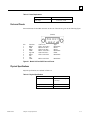
1
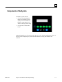
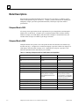
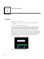
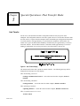
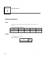
Datapanel
Operator Interface Products
Datapanel
30 and 50 Series
User's Manual
GFK-1657A
March 2001
GFL-002
Warnings, Cautions, and Notes
as Used in this Publication
Warning
Warning notices are used in this publication to emphasize that hazardous voltages,
currents, temperatures, or other conditions that could cause personal injury exist in this
equipment or may be associated with its use.
In situations where inattention could cause either personal injury or damage to
equipment, a Warning notice is used.
Caution
Caution notices are used where equipment might be damaged if care is not taken.
Note:
Notes merely call attention to information that is especially significant to understanding and
operating the equipment.
This document is based on information available at the time of its publication. While efforts
have been made to be accurate, the information contained herein does not purport to cover all
details or variations in hardware or software, nor to provide for every possible contingency in
connection with installation, operation, or maintenance. Features may be described herein
which are not present in all hardware and software systems. GE Fanuc Automation assumes no
obligation of notice to holders of this document with respect to changes subsequently made.
GE Fanuc Automation makes no representation or warranty, expressed, implied, or statutory
with respect to, and assumes no responsibility for the accuracy, completeness, sufficiency, or
usefulness of the information contained herein. No warranties of merchantability or fitness for
purpose shall apply.
©Copyright 1999—2001 GE Fanuc Automation North America, Inc.
All Rights Reserved.
Preface
Content of This Manual
This manual describes features, installation, and operation of the Datapanel Model 30 and 50
products.
Chapter 1.
Quick Start: provides a simplified introduction and operation guide.
Chapter 2.
Introduction to the Datapanel Range and Models 30/35 and 50/55: provides
an overview of capabilities, configuration, and system components; provides a
brief functional description of each of the Datapanel models and outlines features
and capabilities.
Chapter 3.
Installing the Hardware: outlines Datapanel installation.
Chapter 4.
Operation Guide: provides operational guidelines for Run Mode scenarios.
Chapter 5.
Special Operations: Host Transfer Mode: outlines the use of the Mode menu.
Chapter 6.
Specifications: provides tables listing the various hardware, technical, electrical,
and other Datapanel system specifications.
Appendix A.
Error Codes: lists the standard communications block and system error codes.
Appendix B.
Glossary: provides a glossary of terms applicable to Datapanel operation.
Related Publications
GFK-1658
GFK-1657A
Data Designer Software User’s Guide
iii
Contents
Chapter 1
Quick Start ...................................................................................................... 1-1
Installing the Datapanel .......................................................................................... 1-1
Starting Up............................................................................................................. 1-1
Viewing Other Pages .............................................................................................. 1-1
Modifying the Process – Models 50 and 55 Only .................................................... 1-1
Using Pre-Programmed Write Functions – Models 50 and 55 Only......................... 1-2
Chapter 2
Introduction to the Datapanel Range and Models 30/35 and 50/55 .............. 2-1
Strong Commonality With Broad Range of Capabilities................................................ 2-1
Configuration Software................................................................................................. 2-2
Industrial Housing ........................................................................................................ 2-2
Components of the System............................................................................................ 2-3
Model Descriptions....................................................................................................... 2-4
Datapanel Models 30/35 ......................................................................................... 2-4
Datapanel Models 50/55 ......................................................................................... 2-4
Minimum Customer Supplied Hardware ....................................................................... 2-5
Chapter 3
Installing the Hardware .................................................................................. 3-1
Physical Characteristics ................................................................................................ 3-1
Mounting Datapanels.................................................................................................... 3-2
Panel Cutout/Mounting........................................................................................... 3-2
Power Supply Connections ..................................................................................... 3-2
Serial Port Connections .......................................................................................... 3-3
Chassis Ground Connection.................................................................................... 3-3
Cables .......................................................................................................................... 3-4
Chapter 4
Operation Guide.............................................................................................. 4-1
Overview...................................................................................................................... 4-1
Typical Operation Scenarios ......................................................................................... 4-2
Routine Processing ................................................................................................. 4-2
Modifying the Process – Models 50/55 Only........................................................... 4-2
Selecting a Tag and Entering a Value .................................................................... 4-2
Special Drive Out Capabilities — Enhanced Drive Out.......................................... 4-2
Chapter 5
Special Operations: Host Transfer Mode....................................................... 5-1
Host Transfer ......................................................................................................... 5-1
Chapter 6
Specifications................................................................................................... 6-1
Hardware Specifications ................................................................................................ 6-1
Display................................................................................................................... 6-1
Backlight................................................................................................................ 6-1
Keypad – Model 50/55 Only................................................................................... 6-2
GFK-1657A
v
Contents
Technical Specifications ................................................................................................ 6-2
Electrical Specifications ................................................................................................ 6-2
Power Requirements............................................................................................... 6-2
Ports and Pinouts .................................................................................................... 6-3
Physical Specifications ........................................................................................... 6-3
Environmental Conformity ............................................................................................ 6-4
Appendix A
Error Codes .....................................................................................................A-1
Standard Comms Block Error Codes............................................................................ A-1
System Error Codes ..................................................................................................... A-1
Controller Errors.......................................................................................................... A-1
Appendix B
vi
Glossary ...........................................................................................................B-1
Datapanel 30 and 50 Series User's Manual–March 2001
GFK-1657A
Contents
Figure 3-1. Cutout Dimensions................................................................................................................ 3-2
Figure 3-2. Power Connector Pin-out....................................................................................................... 3-2
Figure 3-3. Datapanel-PC Cable .............................................................................................................. 3-4
Figure 4-1. Function Keys of Datapanel Model 50/55.............................................................................. 4-1
Figure 5-1. Host Transfer Display............................................................................................................ 5-1
Figure 6-1. Models 30/35 and 50/55 Ports and Pinouts............................................................................. 6-3
GFK-1657A
Contents
vii
Contents
Table 2-1. Summary of Datapanel 30/35 and 50/55 Features and Capabilities ......................................... 2-4
Table 3-1. Physical Dimensions and Panel Cutouts.................................................................................. 3-1
Table 6-1. Display Area and Characteristics ............................................................................................ 6-1
Table 6-2. Backlight Type ....................................................................................................................... 6-1
Table 6-3. Keypad Characteristics ........................................................................................................... 6-2
Table 6-4. Technical Specifications ......................................................................................................... 6-2
Table 6-5. Power Requirements............................................................................................................... 6-3
Table 6-6. Physical Specifications ........................................................................................................... 6-3
Table 6-7. Environmental Conformity ..................................................................................................... 6-4
Table 6-8. Test Specifications.................................................................................................................. 6-4
viii
Datapanel 30 and 50 Series User's Manual–March 2001
GFK-1657A
Chapter
Quick Start
1
This section is provided as a simplified introduction and operation guide. See subsequent chapters
for more detailed information and explanation.
Installing the Datapanel
After positioning the Datapanel in the cutout, drill four 3/16” holes in the appropriate locations
for the four mounting studs. Cut straight lines between the holes to form an opening for the OI.
Carefully insert the OI from the front of the panel. Use the provided 8/32 nuts to snug down the
OI to the panel. Be careful not to over tighten the nuts as it may cause damage to the OI. Refer to
Chapter 4 for cutout dimensions.
Connect the PLC-Datapanel cable between the PLC and the Datapanel. Connect the Datapanel
power.
Starting Up
On power-up, the Datapanel will enter Run Mode and begin normal operation. The Start Up page
will be displayed if one was specified during configuration with the configuration software.
Otherwise, the first configured page will be displayed. Two lines of text display are available for
system use.
Viewing Other Pages
For a process that is running routinely, you would likely display a page which provides a good
summary of process conditions. Other pages provide alternate views of the operation of the
or keys.
process. You can scroll through the pages by pressing the
Î Í
Modifying the Process – Models 50 and 55 Only
An operator can modify the ongoing process by using the edit function or using a pre configured
function key write operation. This enables fresh values to be transmitted for any configured tag.
Edit Function – Models 50 and 55 Only
is
The edit function allows selection of any editable value displayed on the screen. When
pressed, the first value on the screen is highlighted. To edit this value, simply begin typing a value
GFK-1657A
1-1
1
using the numeric keys. To select another value, simply press the arrow keys to navigate to
another displayed value.
Using Pre-Programmed Write Functions – Models 50 and 55 Only
Five types of write functions can be assigned to function keys: Toggle, Ramp, Jog, Recipe, and
Direct Write.
Toggle. Pressing the F-key defined for the toggle function will invert the value of the configured
item. For example, this could be used to switch a valve from on to off.
Î Í
Ramp. Pressing the F-key defined for the ramp function will display the current value and allow
this value to be modified by pressing the left-right arrow keys ( or ). The new value is
.
confirmed by pressing
Jog (Momentary). Pressing and holding the F-key defined for the function will continuously send
a value (set or reset) to the configured item while the F-key is depressed. When the operator
releases the F-key, the opposite value will be sent.
Recipe. Pressing the F-key defined for the recipe function will run the recipe feature configured.
This can load a group of recipe tags with pre-defined values, transmit a group of recipe tags down
to the PLC device, or perform both of these tasks with just one press of a key.
Direct Write. Pressing the F-key defined for the direct write function will either:
1-2
1.
Write a preconfigured value.
2.
Enable the operator to input a value to write.
Datapanel 30 and 50 Series User's Manual – March 2001
GFK-1657A
Chapter
2
Introduction to the Datapanel Range and Models
30/35 and 50/55
The Datapanel Range consists of a series of low-cost Human-Machine Interfaces enabling the
transfer of data from a Programmable Logic Controller (PLC) and other intelligent control devices
to a comprehensive operator terminal. Datapanels are self-contained, solid state industrial display
systems incorporating their own display screens and keypads. Datapanel Range Operator
Interfaces (OIs) are an ideal replacement for discrete operator input and annunciation devices.
Because of its many configurable options, a Datapanel can meet applications ranging from simple
pushbutton replacement to complex interfaces beyond the capabilities of most small OIs.
Strong Commonality With Broad Range of Capabilities
With a uniform software and hardware architecture, Datapanels allow the user to produce an OI
consistent with application budget and performance requirements while maintaining the ability to
upgrade. An expanding library of over 80 controller protocols is included with each Datapanel,
meaning that a change in control hardware only requires reconfiguring communications and does
not mean re-implementing the OI.
With a consistent architecture, Datapanel hardware is scaled to meet the cost and performance
requirements of each particular model. That means application software can run on all models,
providing extensive functionality on even the lowest priced Datapanel. Application software
makes Datapanels perform with efficiency. A wide range of applications software is built into
every model.
An Operator Interface application is not restricted to emulating push buttons. Application
software in Datapanels supports development of far more useful OI systems. Operator Interface
software is included in every Datapanel. The software supports configuration of simple or
complex OIs.
Standard features of most Datapanel models include:
GFK-1657A
•
Controller Communications. Read and write data to the control equipment via a serial port.
•
Integrated Keypad. Includes programmable function keys (except models 30/35).
•
Broad Protocol Support. Numerous protocols supported.
•
Analog and Digital Tag Scaling. Convert raw data to and from engineering units and adds
tag name information.
2-1
2
•
Display Real-Time Data. Provide information on the current state of the plant process.
•
Optional Display Modes. Continuous updates, update continuously only when page is
displayed, update once when page is first displayed.
•
Graphic Page Display. Display static and dynamic text on up to 200 user configured pages
per Datapanel. Up to 20 dynamic elements may be updated from the controller per page.
•
Softkeys. Five keys per page and 200 pages, for more than 1000 user-defined buttons per
Datapanel. Buttons may change pages, write data, or perform other OI functions (except for
models 30/35).
•
NEMA 4X/4/12 Rated. Ruggedized for harsh industrial environments.
Configuration Software
Configuration of a Datapanel is quick and easy. Datapanels feature a common software
environment, which means that configuring for one model is just like configuring for another.
That increases productivity and decreases the time required to bring a Datapanel on-line. Data
Designer, a PC-based tool operating under Windows® is used to create a database for the
Datapanel. The database and communications protocol are loaded to the Datapanel via a serial
port, and the OI can then be put on-line. Data Designer is sold separately. A single copy of Data
Designer can be used to configure any of the Datapanel Range. Data Designer requires a PCcompatible computer running Windows 95®, Windows 98® or Windows NT®.
Industrial Housing
Datapanels are designed for use in demanding industrial applications. With over 15 years’
experience in meeting the requirements of industrial users, Datapanels avoid the problems that
can plague lesser-quality products. All hardware is designed to meet industrial application
requirements. Datapanels are of compact, shallow design. All front external surfaces are sealed
and protected against the penetration of water and foreign particles. Datapanels are ideally suited
for use as ruggedized panel-mounted units in harsh industrial environments.
Windows 95®, Windows 98®, and Windows NT® are registered trademarks of Microsoft Corporation.
2-2
Datapanel 30 and 50 Series User's Manual – March 2001
GFK-1657A
2
Components of the System
A Datapanel system includes:
•
One unit from the Datapanel
Range, incorporating an LCD
display screen and membrane
keypad (except models 30/35,
which are message centers only)
•
One Operator’s Manual (this
book)
Although Datapanels are self-contained units, the use of a PC, with the configuration software, is
necessary when configuring the system and when databases are being downloaded to the
controller.
GFK-1657A
Chapter 2 Introduction to the Datapanel Range
2-3
2
Model Descriptions
Brief descriptions of Datapanel Models 30/35 and 50/55 are given below. A summary of their
features and capabilities is given in Table 2-1. Chapter 3 provides information on installing the
Datapanels, Chapter 4 provides operational information, and Chapter 6 provides detailed
specifications.
Datapanel Models 30/35
If a message center type interface fits the requirements for your OI application, then Datapanel
Models 30/35 are the answer. A bright 2 line x 20-character display offers excellent visibility.
Model 30’s display is an LED display, while the model 35 display is vacuum fluorescent (VF).
An RS232-422 serial port is available (9 pin D-type connector).
Datapanel Models 50/55
Datapanel Models 50/55 provide a low-end operator interface that includes some function keys
and data entry keys. A bright 2 line x 20-character display is provided. Model 50’s display is an
LED display, while the model 55 display is VF. An RS232-422 serial port is provided. Four
function keys/LEDs and five data entry keys are available.
Table 2-1. Summary of Datapanel 30/35 and 50/55 Features and Capabilities
Features
2-4
30/35
50/55
Processor
Dallas Semiconductor 80C320
Dallas Semiconductor 80C320
Display capability with minimum text
size
20 char
2 lines
20 char
2 lines
Database Size
32K
32K
Backlight
LED/VF
LED/VF
Memory, Flash
128kb Flash
128KB Flash
Memory, SRAM or DRAM
32KBSRAM
32KB SRAM
Serial Ports
One RS232/RS485
One RS232/RS485
Standard Software Features
Tag Scaling, Text Page
display, Read to controller,
Downloadable Database and
Protocol.
Tag Scaling, Text Page
display, Read to controller,
Recipe handling, Configurable
Function Keys, Downloadable
Database and Protocol.
Function Keys per Page
None
Five
Data Entry Keypad
None
Four
Analog Tags
100
100
Digital Tags (2 bits per tag)
100
100
Display Pages
200
200
Datapanel 30 and 50 Series User's Manual – March 2001
GFK-1657A
2
Minimum Customer Supplied Hardware
A PC or equivalent running Windows, is required to configure Datapanels and transfer databases
and protocol to the Datapanel:
GFK-1657A
•
486 DX2/66
•
8 MB RAM
•
VGA Color Display
•
10 MB Hard Disk Space
Chapter 2 Introduction to the Datapanel Range
2-5
Chapter
Installing the Hardware
3
Physical Characteristics
Datapanels 30 and 50 have a single metal plate forming the front of the unit. The metal front is
mounted to the panel using 4 studs. A gasket is used to ensure conformity to IP65 (NEMA
4X/4/12) rating.
The rear section of the housing is like an open, rectangular box that fits over the system
electronics. The rear section presses into the back of the front plate and is held to it by two
Phillips-head screws. The physical dimensions are shown in and Table 3-1.
Table 3-1. Physical Dimensions and Panel Cutouts
Features
GFK-1657A
Model 30/35/50/55
Dimensions (Inches)
5.90 Wide x 4.10 High x
1.75 Deep
Panel Cutout (Inches)
5.00 Wide x 3.50 High
3-1
3
Mounting Datapanels
Panel Cutout/Mounting
Drill four 3/16” holes in the appropriate locations for the four mounting studs. Cut straight lines
between the holes on the long sides of the cutout to form an opening for the OI. Carefully insert
the OI from the front of the panel. Use the provided 8/32 nuts to snug down the OI to the panel.
Be careful not to over tighten the nuts as it may cause damage to the OI.
.15"
3/16" diameter
127mm
.15"
(5")
88.9mm
CUTOUT
134.6mm
(3.5" )
(5.3")
Figure 3-1. Cutout Dimensions
Power Supply Connections
The power supply used to power the units must provide between 10VDC and 30VDC, and must be
capable of sustaining at least 2.5W.
Using the supplied power connector, connect +10VDC to +30VDC to the power connector. Pin 1
is identified on the “plug” side of the connector and should have the positive terminal of the
power supply connected to it. Connect the power supply return (negative lead) to pin 2. The
power input is reverse polarity protected, so if the wiring is backwards, you will not damage the
OI.
Figure 3-2. Power Connector Pin-out
3-2
Datapanel 30 and 50 Series User's Manual – March 2001
GFK-1657A
3
Caution
It is extremely important that you do NOT connect the chassis ground of the
power supply or the OI to the power return (negative terminal) of the power
supply. In some cases, power supplies have shunts to do this, if your power
supply has the shunt installed, you MUST remove it!
Serial Port Connections
Models 30/35 and 50/55 support RS232 operation and either 2 or 4-wire RS422/RS485 operation.
The RS422/RS485 port has a tri-statable output that may be used on networks where multiple OIs
are connected to a single or multiple PLCs (the protocol must support networking for this to be
possible).
When networking is supported on a particular PLC, the RXD+/TXD+ and RXD-/TXD- pins are a
2-wire (multidrop), half-duplex connection. The OI will automatically handle tri-stating the TXD
outputs when networked.
Chassis Ground Connection
The chassis ground connection is a required safety connection. It also provides a means for ESD
to return to ground without disturbing the electronics within the OI. The panel the OI is mounted
in should be solidly grounded to an earth ground. If the OI is mounted on a door, a good solid
ground braid must be connected between the panel door and the panel housing (an engine
grounding strap works well for this). Do not rely on the hinges for the chassis ground as over
time they will corrode and the earth connection will become higher impedance, thereby reducing
the effectiveness of the earth connection.
Connect a heavy braid between one of the OI mounting studs and a good earth connection. It is
best to use the same grounding strap mentioned above for connection to the OI stud. This will not
only provide a chassis ground to the door of the enclosure, but will also provide a chassis ground
to the enclosure of the OI. Be sure to use a star washer that will cut through any paint on the
enclosure and ensure a solid connection. If you are unsure about the connection, use an ohmmeter
to check for resistance when the connection is made.
Caution
You must NEVER return current on the chassis ground. The chassis
ground is for safety only and must never carry current. Doing so will cause
damage to sensitive electronics within your system. Always use the power
supply return circuit to return current to the power supply when using
switches, motors, etc. If your system will run without the power supply
return connected, you have a potentially hazardous installation.
GFK-1657A
Chapter 3 Installing the Hardware
3-3
3
Cables
Two cables are required when using the Datapanels:
•
The download cable is used when transferring databases or protocols from the
configuration software to the Datapanel. The cable enables connection to a standard PC.
For nonstandard PCs, consult the PC manual to check the pin configuration at the PC
end of the cable. This cable is supplied with the configuration software.
•
The cable used to connect Datapanels to the controller. As a general guide, the only pin
connections required at the Datapanel end are Tx, Rx, Signal, Ground. Refer to your
controller documentation for details of connections at the controller end. (Wiring
diagrams are also available in the Protocol help and documentation that is part of the
configuration software package.) This cable is not supplied with the Datapanel.
Figure 3-3. Datapanel-PC Cable
3-4
Datapanel 30 and 50 Series User's Manual – March 2001
GFK-1657A
Chapter
Operation Guide
4
Overview
Datapanels operate in one of two modes:
•
Run — enables real time processes to be viewed from configured displays downloaded to
Datapanel.
•
Offline — enables the loading databases and protocols
On power-up, the Datapanel will enter Run Mode and begin normal operation. The Start Up page
will be displayed if one was specified during configuration with the configuration software.
Otherwise, the first configured page will be displayed. The screen layouts of all Datapanels are
similar in appearance, but vary slightly according to the capabilities of the various models.
One of the obvious differences between various Datapanel models is the number and location of the
function keys (F-keys). The Model 030/035 does not have any function keys. The Model 050/055
has five function keys. Any of the keys may be assigned other functions during configuration with
the configuration software. They may have different functions on different display pages. When
the keys are reprogrammed from their default value, they are often referred to as softkeys.
The default Run Mode function keys are labeled F1 through F5.
Figure 4-1. Function Keys of Datapanel Model 50/55
GFK-1657A
4-1
4
Typical Operation Scenarios
Routine Processing
For a process that is running routinely, you would likely display a page which provides a good
summary of process conditions. The page might include a analog display showing performance
over some time period or other elements showing constantly updating values of parameters
indicating process efficiency (e.g., cans filled per hour, gallons of fruit juice per minute, kW of
electricity consumed).
Modifying the Process – Models 50/55 Only
An operator can modify the ongoing process by using the Edit function of the Datapanel. This
enables fresh values to be transmitted to any tag displayed with the editable attribute set.
Selecting a Tag and Entering a Value
The edit function allows selection of any editable value displayed on the screen. When
is
pressed, the first value on the screen is underlined. To edit this value simply begin typing a value
. (If an invalid value is entered, the number is cleared and the
using the numeric keys and press
user is positioned to enter another value.) To select another value, simply press the arrow keys to
navigate to another displayed value.
Special Drive Out Capabilities — Enhanced Drive Out
Five types of Enhanced Drive Out can be configured: Toggle, Ramp, Jog, Recipe, and Direct
Write.
Toggle Pressing the Function-key defined for the toggle function will invert the value of the
configured item. For example, this could be used to switch a valve from on to off.
Î Í
Ramp Pressing the Function-key defined for the ramp function will display the current value and
allow this value to be modified by pressing the left-right arrow keys ( or ). The new value is
.
confirmed by pressing
Jog Pressing and holding the Function-key defined for the function will continuously send a value
(set or reset) to the configured item while the F-key is depressed. When the operator releases the Fkey, the opposite value will be sent.
Recipe Pressing the F-Key defined for the recipe function will run the recipe feature configured.
This can load a group of recipe tags with pre-defined values, transmit a group of recipe tags down
to the PLC device, or perform both of these tasks with just one press of a key.
Direct Write Pressing the Function-key defined for the direct write function will either:
4-2
1.
Drive Out a preconfigured value.
2.
Request operator input of a value to Drive Out.
Datapanel 30 and 50 Series User's Manual – March 2001
GFK-1657A
Chapter
Special Operations: Host Transfer Mode
5
Host Transfer
For the 30/35, start the transfer from the configuration software and cycle power on the
Datapanel. The configuration software will send a signal to the 30/35 to enter Host Transfer mode
and will wait for a response from the Datapanel before transmitting the configuration information.
To exit the transfer, wait approximately 15 seconds after the completion of the transfer. )For
models 50/55, press and hold the F1 and F5 keys simultaneously for approximately 3 seconds to
enter Host Transfer. Exit from Host Transfer is automatic within approximately 15 seconds if
nothing is downloaded. You can also press any key once the transfer is done to exit.
Figure 5-1. Host Transfer Display
The actual transfer of the data is under the control of the PC. The following messages will be
displayed in the message area of the display:
When downloading a Protocol:
Loading Communications Protocol ... and on the same line when complete, Protocol
installed.
When downloading a Database:
Loading Database ... and on the same line when complete, Database installed.
When uploading a Database:
Uploading Database ... and on the same line when complete, Database transferred.
When a communications error occurs:
Transfer Failed
GFK-1657A
5-1
Chapter
Specifications
6
Hardware Specifications
Display
The display area and display characteristics of the 30/35 and 50/55 models are specified in
Table 6-1.
Table 6-1. Display Area and Characteristics
Features
Display Type
Display capability with
minimum text size
30
35
50
55
LCD
VF
LCD
VF
20 char
2 lines
20 char
2 lines
20 char
2 lines
20 char
2 lines
Backlight
The backlight type is given in Table 6-2.
Table 6-2. Backlight Type
Features
Backlight
GFK-1657A
30/50
Models
LED
6-1
6
Keypad – Model 50/55 Only
Datapanel models 50/55 incorporate built-in membrane keypads with audible feedback as
described in Table 6-3.
Table 6-3. Keypad Characteristics
Features
50/55
Function Keys per Page
5
Data Entry Keypad
10 numeric keys (5 with
shift for 5), Left/Right
arrow keys, Enter key,
Backspace key
Touch Screen
No
Technical Specifications
The technical specifications are given in Table 6-4.
Table 6-4. Technical Specifications
Features
30/35/50/55
Processor
DS80C320
Memory, Flash
128KB Flash
Memory, SRAM or DRAM
32K SRAM
Database Size
32K
Serial Ports
RS232/422 port
Additional Ports
No
Electrical Specifications
Power Requirements
The power requirements are given in Table 6-5.The steady state current consumption of the
Datapanel is dependent on the supply voltage. At power-up, the Datapanel briefly requires a larger
current to operate correctly. To ensure correct power-up, the external power supply must be able to
provide a current of at least 1 A, irrespective of the supply voltage. The power supply used to
power the models must provide between 10VDC and 30VDC, and must be capable of sustaining at
least 2.5W.
The power for Datapanel Models 30/35 and 50/55 is supplied through the 2-pin power connector
at the bottom of the unit.
6-2
Datapanel 30 and 50 Series User's Manual – March 2001
GFK-1657A
6
Table 6-5. Power Requirements
Features
30/35 and 50/55
Power Input
10-30 VDC, 2.5W
Ports and Pinouts
Ports and Pinouts for the DB9 connector on the rear of the unit are given in the following figure:
(female)
Pin
1
2
3
4
5
6
7
8
9
Function
RXD+
TXD
RXD
TXD+
Sig Gnd
RXDN/C
N/C
TXD-
Connect To
TXD+ on PC/PLC
RXD on PC/PLC
TXD on PC/PLC
RXD+ on PC/PLC
Gnd on PC/PLC
TXD- on PC/PLC
Type
RS422/485
RS232
RS232
RS422/485
Either
RS422/485
RXD- on PC/PLC
RS422/485
Figure 6-1. Models 30/35 and 50/55 Ports and Pinouts
Physical Specifications
Physical specifications are outlined in Table 6-6.
Table 6-6. Physical Specifications
30/35 and 50/55
GFK-1657A
Chapter 6 Specifications
Dimensions (Inches)
5.90 Wide x 4.10 High x
1.75 Deep
Weight (lb.)
1.5
Panel Cutout (Inches)
5.00 W x 3.50 H
6-3
6
Environmental Conformity
Environmental conformity is given in Table 6-7.
Table 6-7. Environmental Conformity
Features
Models 30/35 and 50/55
NEMA, UL, CUL
4/12, UL, CUL, Class I Div II
All models in the Datapanel Range are designed to satisfy the requirements and conditions of the
following specifications. All units in the Datapanel Range remain operational when tested for
temperature and humidity. Table 6-8 provides the test specifications.
Table 6-8. Test Specifications
Models 30/50
6-4
Operating
Temperature
-10 to +50 °C
Storage
Temperature
-25 to +70 °C
Humidity
5 to 85 % non-condensing
Datapanel 30 and 50 Series User's Manual – March 2001
Models 35/55
-10 to +60 °C
GFK-1657A
Appendix Error Codes
A
Standard Comms Block Error Codes
101
Timeout
102
Checksum Received Error
103
Bad Character Received Format Error
104
Bad Message Framing Error
105
Bad Message Format Received
106
NAK Response Received
107
Comms Block Format Error
108
Invalid Command
System Error Codes
28
More than 64 comms blocks activated at the same frequency.
29
More than 8 page-activated comms blocks activated by the page.
120
Tag Conversion error — unreasonable limits configured in an Analog Tag Record.
121
No Comms File.
122
No Comms Blocks.
123
Invalid Comms Block Time base.
124
Invalid Comms Block Type.
Controller Errors
If any errors are displayed which are not listed in the above tables, reference should be made to
the configuration software Help system or to the controller documentation.
GFK-1657A
A-1
Appendix Glossary
B
ACK
Acknowledgment
Alphanumeric
Alphanumeric
Display
Analog
Analog Tag
Analog Variable
ANSI
Application
Program
ASCII
Backup
Baud, Baud Rate
The characteristic of being able to take on any of a continuously variable range of
values.
An identifying name for an analog variable. See also Tag.
A term used to describe a 16-bit integer, 32-bit integer, or floating-point number
which may take many values.
A character set optimized for the support of the French, German and Scandinavian
characters.
A user-defined program written to perform specific actions in addition to the system
software functions.
American Standard for Computer Information Interchange. Defines what numeric
codes are used to represent numbers, punctuation and letters of the alphabet.
To copy and store data as a precaution against loss or damage. Also, the copy so
created.
User-configurable rates at which communication takes place between the system and
the controller.
Blinking
The effect created on a portion of a graphic which will allow it to change between
two defined states at a specific rate.
Boot
Browse
Byte
Permanently resident Firmware used to load the main software and configuration.
Scanning data in order to locate a required item.
A group of 8 consecutive bits.
Commands
Information sent from the Datapanel to the controller to control or modify the plant
process.
See Communications Block.
A group of user configured information describing a particular communications
operation between the Datapanel and the controller.
Comms Block
Communications
Block
(Comms Block)
Communications
Protocol
Configure
GFK-1657A
See Acknowledgment.
The action taken by the user to indicate the acceptance of the information presented
by the system.
Alphabetic and numeric characters only.
A display of alphabetic and numeric characters only.
The “language” to be used when the system communicates with a controller. It
contains the rules used to establish contact, receive/transmit data, detect transmission
errors, etc.
To set up the display system in accordance with the needs of a particular user. This
includes user-specific displays, alarm criteria, etc.
B-1
B
Contiguous
Controller
Data
Data Designer
Database
A Windows-based tool for configuring Datapanels.
A structured set of data. In the Datapanel, databases are configured to customize the
product to satisfy the needs of the user.
Digital Tag
A self-contained, solid-state industrial display system incorporating its own display
screen and keypad.
The characteristic of being able to take on only one of two possible states or
conditions.
An identifying name for a digital variable. See also Tag.
Download
Drive Out
Transmitting data from the configuration tool to the Datapanel.
The capability of the Datapanel which allows it to send information to the controller.
Drop-Down
Dynamic
Firmware
F-Key
Flash memory
A menu or list which appears in Windows upon selection of a menu item.
Any data element (tag value, graphic item, etc.) that can have changing values.
Software (database, applications) stored in non-volatile memory, e.g., EPROM.
See Function Key.
See Firmware.
HMI (HumanMachine Interface)
Host
I/O
Import
Device enabling the two way transfer of data between a human and machine.
Datapanel
Digital
Input/Output
Keyboard
Keypad
LED
Macro
Master
Membrane
Mimic
Mini-Alarm Log
NEMA
Network
Off-line
On-line
Operator
Overview Group
B-2
A group of items stored in adjacent locations.
An industrial device that handles the Input/Output of plant voltages and signals, e.g.,
a Programmable Logic Controller.
Information relating to the operation of the plant process.
Device on which the controlling software is resident.
See Input/Output.
The ability to transfer configuration information into the Datapanel configuration tool
from another application like a spread sheet.
A general expression for the input and output of binary data to or from a device.
A collection of physical keys used by the user to communicate with the computer
system.
An operator keyboard with a reduced number of keys, e.g., numeric and/or function
keys.
Light Emitting Diode. Typically used as a status indication light.
A collection of instructions or program statements which can be activated
collectively.
The device controlling network communications.
A continuous film intended to protect a device from the ingress of dust or liquid.
A display which factually represents the plant. It provides the status of each
displayed plant item. Mimics may be shown on monitors or wall displays.
One of the Alarm area displays available when using the Datapanel. This display is
found on all the Run Mode displays in the upper part of the screen.
National Electrical Manufacturers Association. A group which sets American
standards for enclosures which protect electronic equipment from the adverse affects
of liquids, ingress of dust and physical shocks. Also, the standard created.
An interconnected group of communicating devices.
A condition where run time operations are suspended, so that system settings can be
changed.
The system is communicating to external devices with dynamic data being updated.
The person who uses the system for its practical purpose such as to interface with the
plant process. Not necessarily the one who configured the system. See also User.
A set of tags configured to be displayed together.
Datapanel 30 and 50 Series User's Manual – March 2001
GFK-1657A
B
Page
Parallel
One of 200 user configurable displays on the Datapanel.
A data transfer mechanism using multiple transfer paths.
Parameter
Parity
A value set when the system is configured.
The means of checking the validity of a data character.
Password
A code used to show the authority of the user to gain access to various sensitive
features of the system. For example, changes to the display design would normally be
password-protected to guard against changes by unauthorized users.
PC
Pixel
IBM Personal Computer or any computer generically similar.
The smallest picture element of a display surface that can be independently assigned
a color or intensity.
A series of actions or treatments designed to produce a desired end under the control
or monitoring of a PLC or other intelligent controller.
Plant Process
PLC
Process
Programmable Logic Controller.
See Plant Process.
Process Variable
Programmable
Logic Controller
A variable parameter of the production process.
An industrial device that handles the Input/Output of plant voltages and signals.
Protocol
RAM
Ramp Drive-out
The format, structure and procedure required to communicate with a controller.
Random Access Memory.
Pre-configured analog drive-out (Tag/Register) with a specific increment/decrement
value.
Data read from the controller before being scaled into engineering values.
Current data.
The operating state of the system. See also On-line.
Raw data whose value has been modified to conform to prescribed engineering units.
A data transfer mechanism using a single transfer path.
The device which responds to a master over a network.
An area of the database containing the information for a particular tag.
A group of Tag Values in the Datapanel.
The current value of the tag. This may be a scaled engineering value associated with
the Tag Record.
The action of inverting the value of a two-state item, such as a bit or a two-state
digital tag.
Raw Data
Real-Time Data
Run Time
Scaled Data
Serial
Slave
Tag Record
Tag Table
Tag Value
Toggle
Upload
A group of icons which provide easy access to other windows, menus or operations.
An area of the screen dimensionally defined to produce a program response when
touched or pressed.
Database transfer from Datapanel to WinCfg.
User
The person using WinCfg to configure a Datapanel. See also Operator.
Toolbar
Touch Region
GFK-1657A
Appendix B Glossary
B-3
Index
B
Backlight, 6-1
C
Cables, 3-4
chassis ground, 3-3
Cutouts, panel, 3-1
D
Datapanels
description, 2-4
features and capabilities, 2-4
Model 30/35, 2-4
Model 50/55, 2-4
mounting, 3-2
operating modes, 4-1
overview, 2-1
Dimensions
panel cutouts, 3-1
M
Modifying the process, models 50/55 only, 4-2
Mounting Datapanels, 3-2
O
Offline mode, 4-1
Operating modes
overview, 4-1
P
Panel cutouts, 3-1
Physical specifications, 6-3
Pinouts, 6-3
Ports, 6-3
Power requirements, 6-2
Q
Quick Start, 1-1
Direct Write, 4-2
E
Electrical Specifications, 6-2
Enhanced drive out, 4-2
Entering a value, 4-2
Environmental conformity, 6-4
Error codes, A-1
F
Function keys
run mode, 4-1
G
Glossary, B-3
H
Hardware specifications, 6-1
Host transfer, 5-1
I
Installation, 3-1
R
Ramp, 4-2
Recipe, 4-2
RS232, 3-3
RS422/RS485, 3-3
Run mode, 4-1
S
Selecting a tag, 4-2
Special drive out capabilities, 4-2
Specifications
display, 6-1
electrical, 6-2
hardware, 6-1
keypad, 6-2
physical, 6-3
ports and pinouts, 6-3
technical, 6-2
T
Technical specifications, 6-2
Test specifications, 6-4
Toggle, 4-2
Typical operation scenarios, 4-2
J
Jog, 4-2
GFK-1657A
Index-1