1
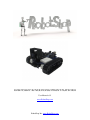
RobotShop Rover Development Platform
User Manual v1.5
www.RobotShop.com
RobotShop Inc. www.RobotShop.com
Contents
Specifications .................................................................................................................. 3
Parts List ......................................................................................................................... 4
Basic Kit ..................................................................................................................... 4
Upgrade Kit ................................................................................................................. 4
Complete Kit ............................................................................................................... 4
Additional Parts Required ............................................................................................ 5
Project Ideas .................................................................................................................... 5
Assembly ........................................................................................................................ 6
Basic Platform ............................................................................................................. 6
Microcontroller ........................................................................................................... 8
Servos ......................................................................................................................... 9
Battery Holders ........................................................................................................... 9
Breadboards .............................................................................................................. 10
Motor Controller ....................................................................................................... 11
Electronics and Wiring .................................................................................................. 11
Support.......................................................................................................................... 12
Arduino Code ................................................................................................................ 15
RobotShop Inc. www.RobotShop.com
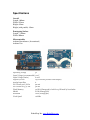
Specifications
Overall
Length: 160mm
Width: 155mm
Height: 65mm
Height (with pan/tilt): 95mm
Prototyping Surface
Length: ~120mm
Width: 100mm
Microcontroller
Arduino Duemilanove (discontinued)
Arduino Uno
Operating Voltage
5V
Input Voltage (recommended) 7-12V
Input Voltage (limits)
6-20V
Digital I/O Pins
14 (of which 6 provide PWM output)
Analog Input Pins
6
DC Current per I/O Pin
40 mA
DC Current for 3.3V Pin
50 mA
Flash Memory
32 KB (ATmega328) of which 0.5 KB used by bootloader
SRAM
2 KB (ATmega328)
EEPROM
1 KB (ATmega328)
Clock Speed
16 MHz
RobotShop Inc. www.RobotShop.com
Parts List
Basic Kit
The following parts are included with the basic platform kit:
•
•
•
•
•
•
•
•
•
•
1x Metal Frame
4x Phillips Screws
4x Nylon Snap Rivets
2x Nylon F/F Standoffs
2x Nylon Acorn Nuts
2x 5/8” Nylon Screws
1x 9V Battery Holder
2x Small Phillips screws
6x Rubber Spacers
1x Nylon Clip
(RB-Lyn-84)
(RB-Lyn-233)
(RB-Lyn-254)
(RB-Lyn-223)
Upgrade Kit
The following parts are included in the upgrade kit, along with all parts in the basic kit:
•
•
•
•
2x Pololu Motors
1x Johnny Robot GM2/38/9 Track Kit
2x Shoulder bolts with fasteners and hex nut
1x AA Battery holder
(RB-Sbo-07)
(RB-Jon-10)
(RB-Pol-75)
(RB-Spa-138)
Complete Kit
The following additional parts are included with the complete kit and include both the
basic kit and upgrade kit.
•
•
•
•
•
•
•
•
•
•
1x Arduino Diecimilla
1x Sharp GPD12 Infrared Range Sensor
1x Sharp GP2 IR sensor cable
1x Pololu Micro Dual Motor Controller
1x Lynxmotion Pan and Tilt Kit with Servos
3x 170-tie point breadboard
1x 140 Piece Jumper Wire Kit
1x #22 Gauge Hook-up wire
1x Break-away headers
1x On/Off switch
RobotShop Inc. www.RobotShop.com
(RB-Ard-03)
(RB-Sha-01)
(RB-Lyn-164)
(RB-Pol-16)
(RB-Lyn-74)
(RB-Spa-139)
(RB-Ibo-25)
(RB-Ibo-84)
(RB-Spa-153)
(RB-Spa-155)
Additional Parts Required
In order to build the complete kit, you will need the following additional (basic) tools:
• Wire cutter and wire stripper
• Soldering Iron
• Solder
• Phillips Screw Driver
• Allen Wrench Set
• Pliers
• 4xAA batteries (1.2V rechargeable or 1.5V alkaline)
• 1x 9V battery (unless the microcontroller can run off 4.8V)
Project Ideas
The basic rover is intended for you to add standard electronics in order to create a small
autonomous or remote controlled rover. A basic understanding of electronics is
required. Although the kit includes all essential parts to make an autonomous robot, it is
intended to allow you to add your own electronics in order to satisfy your objectives.
This robot differs from others in its size, versatility and cost. The front frame includes
holes for the following parts:
RB-Sct-54 Servocity Servo Hub Horn (Hitec)
Can be used to attach custom parts to the front of the rover
RB-Lyn-99 Lynxmotion Mounting Hub
Can be used to mount tubing to the front of the robot
RB-Lyn-105 Lynxmotion Aluminum Multi-purpose Servo Bracket
This part is ideal for offsetting the arm to the very front of the robot, leaving the entire
surface of the frame for electronics and breadboards.
RB-Lyn-106 Lynxmotion Aluminum L-Connectors can be used to mount items parallel
to the frame either higher or lower such as the following:
RB-Lyn-75 Lynxmotion Aluminum Multi-Purpose Sensor Housing MPSH-01
Used to mount 3 sensors at various angles. This is particularly useful if you are using the
pan/tilt system as the base for a robotic arm.
RB-Sum-13 Robotics Connection Sharp IR Turret
Allows you to more easily connect a variety of different sensors.
RB-Net-04 BasicX Development Kit
Instead of an Arduino, you can use a BasicX starter kit.
RobotShop Inc. www.RobotShop.com
Assembly
Although you are encouraged to develop your own variation of the rover, this Assembly
Guide will take you through the process of assembling the basic robot kit. The guide is
intended to be used with the 3D CAD assembly Guide available online at
www.robotshop.com.
To view the 3D CAD file, you must download Google Sketchup. This is a FREE program
available to download from http://sketchup.google.com The Assembly Guide was made
using Google Sketchup 6. Note: In the 3D drawing, all parts are only roughly drawn in
order to aid with the assembly process. To view the video, select View -> Animation ->
Play.
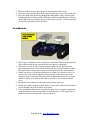
Basic Platform
1. Prior to assembly, be sure to solder the motor wires to the motor. Should you have
purchased the complete kit, you can use the #22 gauge wire and trim any
unnecessary wire.
2. If you wish to modify the platform by adding custom holes, be sure to drill the
holes with the frame on a flat surface, prior to any items being connected.
3. Insert the two motors into the frame and lock them in place using the Phillips
screws.
RobotShop Inc. www.RobotShop.com
4. Insert the drive cog onto the motor shaft and attach it with the small screw
provided.
5. Assemble two sets of tracks with 20 links in each track.
6. Place the track on the drive sprocket and place the idler inside the track, in front
of the connection point. Insert the Shoulder bolt through the idler sprocket and
through the frame. Lock the idler in place with the washer and nut.
RobotShop Inc. www.RobotShop.com
Microcontroller
1. Screw the hex spacers onto the frame using the screws and acorn nuts provided.
Holes are available for the following microcontrollers:
a. Arduino Diecimilla (center rear mounting)
b. Arduino Diecimilla (right rear mounting)
c. BasicX Development Board
d. Parallax Java/Basic Stamp Board
2. Use the Nylon standoffs, acorn nuts and screws to hold your microcontroller in
place. All microcontrollers are mounted at the rear of the robot.
3. The acorn nuts though are used on top of the microcontroller, while the screws
protrude from under the frame.
RobotShop Inc. www.RobotShop.com
Servos
4. Use the snap rivets to hold the base servo in place.
5. Should your kit include the Lynxmotion pan and tilt system, follow the
instructions on the Lynxmotion website for assembly.
6. All items connected to the horn of the base servo should be placed as far forward
as possible to avoid interfering with items placed on either side of the servo.
Battery Holders
1. Place one rubber spacer onto each of the Phillips screws.
2. Place these through the frame with the heads on the top of the frame.
RobotShop Inc. www.RobotShop.com
3. Place two rubber washers onto the screw on the bottom of the frame.
4. Screw the screws into the holes in the battery holder (the screws will self-thread).
5. Place the small white nylon clip through the small rubber-o-ring, and then push
both through the 9V battery holder. Push the assembly though the hole in front of
the AA battery holder and glue in place (white glue or epoxy). All battery holders
are located on the underside of the robot.
Breadboards
1. The design is configured to have all batteries and motors located on the underside
of the robot, freeing up the entire deck for your choice of electronics.
2. The choice is yours as to the location of the breadboards and depends on the
microcontroller chosen. The basic kit includes the low cost but versatile Arduino
Diecimilla and the image above shows possible locations of the 3 breadboards.
3. Should you choose to place the breadboards on either side of the base servo, be
sure that any components connected to those boards do not contact any items
connected to the servo horn. Elecontrics such as Bluetooth and wireless systems
should be placed as far back on the robot as possible to avoid contact with the
servo.
4. Breadboards are connected to the frame using double sided tape.
5. Ideally wires which connect to items under or on the sides of the frame should be
passed through one of the six holes in the frame.
6. It is recommended that you use pre-formed jumper wires to connect components
on the breadboards, and from breadboard to breadboard. Use #22 gauge wires to
connect from the microcontroller to the breadboards.
RobotShop Inc. www.RobotShop.com
Motor Controller
The two motor controllers ideally suited to the kit are the Pololu Micro Dual Motor
Controller (1A) or the Pololu Low Voltage Dual Motor Controller (5A).
Follow the instructions when connecting the motor controller to your microcontroller.
Use the mini breadboards to facilitate connections.
Place the On/Off switch between the Tx of the Arduino and the Rx of the motor
controllers.
REMEMBER: turn OFF the motor controller when downloading your Arduino code
to the Arduino.
Electronics and Wiring
It is recommended that you assemble and test each sub-section before assembling the
entire robot. This will help you troubleshoot any problems as they arise.
4.8V Battery Pack
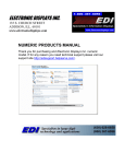
Connect the following pins to the +4.8V (red) of the battery pack*:
Motor Supply (pin1) on Motor Controller
Servo 1 +V (red)
Servo 2 +V (red)
Connect the following pins to the GND (black) of the battery pack (“common ground”)
GND on Arduino and GND (pin2) on Motor Controller
GND (black) of Servo 1
GND (black) of Servo 2
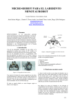
9V Battery Pack
Connect the +9V (red) of the 9V battery to the Vin of the Arduino
Connect the GND (black) of the 9V battery to the GND of the Arduino
When using the 9V battery to power the Arduino, change the jumper on the Arduino from
usb to ext (external).
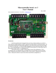
Motor Controller
Connect the +5V (or 3.3V) from Arduino to Logic Supply on Motor Controller
Connect the Tx (pin1) from Arduino to Logic Supply on Motor Controller
Connect a Digital pin (any) from Arduino to Reset pin on Motor Controller
Motor 1 Positive on Motor Controller to Motor 1 Pin
Motor 1 Negative on Motor Controller to Motor 1 Pin
Motor 2 Positive on Motor Controller to Motor 2 Pin
Motor 2 Negative on Motor Controller to Motor 2 Pin
RobotShop Inc. www.RobotShop.com
Servos
Connect each Servo Motor Signal to a digital pin on the Arduino
Note: If the servos are connected directly to the Arduino, they may display erratic
behavior when uploading code to the Arduino.
On/Off switch
Place the On/Off switch between the Tx pin of the Arduino and the motor controller Rx;
this ensures that when downloading a program, only the Arduino is powered.
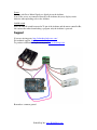
Support
If you are missing parts: http://robotshop.helpserve.com/
For technical support: http://forum.robotshop.ca
To purchase additional or replacement parts: www.robotshop.com
Remember: common ground
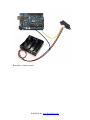
RobotShop Inc. www.RobotShop.com
Remember: common ground
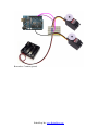
RobotShop Inc. www.RobotShop.com
Remember: Common ground.
RobotShop Inc. www.RobotShop.com
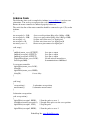
/*
Arduino Code
The following demo code is complied in Arduino (www.arduino.cc) and uses two
subroutines. You are free to copy/paste the code into the Arduino compiler.
Ensure the motor controller is connected properly before use.
The serial data line of the motor controller should be connected to pin 1 (Tx) on the
Arduino.
*/
int servopulse1 = 1250;
int servopulse2 = 1500;
int servopin1 = 9;
int servopin2 = 10;
int motor_reset = 2;
//test servo tilt position (0deg =0 to 180deg =1500)
//test servo pan position (0deg =0 to 180deg =1500)
//yellow wire from servo 1 to digital pin 9
//yellow wire from servo 2 to digital pin 10
//motor reset pin connected to digital pin 2
void setup()
{
pinMode(motor_reset, OUTPUT);
pinMode(servopin1, OUTPUT);
pinMode(servopin2, OUTPUT);
//digitalWrite(motor_reset, LOW);
Serial.begin(9600);
//sets pin as output
//sets pin as output
//sets pin as output
//do not activate motor driver
//communication at 9600 baud
// reset motor controller
digitalWrite(motor_reset, LOW);
delay(50);
digitalWrite(motor_reset, HIGH);
delay(50);
// reset delay
}
void loop()
{
servoposition();
motorcontrol();
}
// subroutine servoposition
// subroutine motor control
//subroutine servoposition
void servoposition()
{
digitalWrite(servopin1, HIGH);
delayMicroseconds(servopulse1);
digitalWrite(servopin1, LOW);
digitalWrite(servopin2, HIGH);
// Start the pulse to servo 1
// Length of the pulse sets the servo position
// Stop the pulse
// Start the pulse to servo 2
RobotShop Inc. www.RobotShop.com
delayMicroseconds(servopulse2);
digitalWrite(servopin2, LOW);
// Length of the pulse sets the motor position
// Stop the pulse
}
//subroutine motor control
void motorcontrol()
{
//left motor
unsigned char buff1[6];
buff1[0]=0x80;
//start byte specific to Pololu motor controller
buff1[1]=0x00;
//Device type byte specific to Pololu controller
buff1[2]=0x01;
//Motor number and direction byte; motor one =00,01
buff1[3]=0x7F;
//Motor speed "0 to 128" (ex 100 is 64 in hex)
for(int i=0;i<4;i++) {Serial.print(buff1[i],BYTE);}
//right motor
unsigned char buff2[6];
buff2[0]=0x80;
//start byte - do not change
buff2[1]=0x00;
//Device type byte
buff2[2]=0x03;
//Motor number and direction byte; motor two=02,03
buff2[3]=0x7F;
//Motor speed "0 to 128" (ex 100 is 64 in hex)
for(int i=0;i<4;i++) {Serial.print(buff2[i],BYTE);}
}
RobotShop Inc. www.RobotShop.com