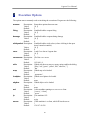
1
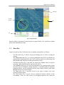
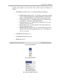
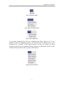
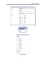
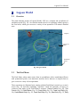
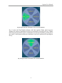
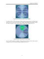
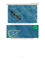
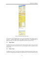
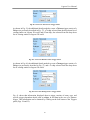
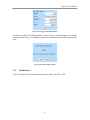
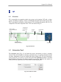
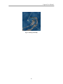
Lagoon User Manual July 25, 2006 Project Team Dr. Sushil Louis Dr. Monica Nicolescu Dr. Sergiu Dascalu Chris Miles Ryan Leigh Adam Olenderski Juan Quiroz David Carr Anil Shankar Lagoon User Manual Table of contents Abbreviations.................................................................................................................. 3 List of Figures................................................................................................................. 4 1 Introduction............................................................................................................... 6 1.1 Overview........................................................................................................... 6 1.2 Menu Bar............................................................................................................ 7 1.3 Lagoon 3D World............................................................................................. 14 1.4 CAT Interface................................................................................................... 14 1.5 SP Interface ...................................................................................................... 14 2 Lagoon World ......................................................................................................... 15 2.1 Overview.......................................................................................................... 15 2.2 The Petal Menu ................................................................................................ 15 2.3 Entity and Group Markers................................................................................. 24 3 CAT ........................................................................................................................ 27 3.1 Overview.......................................................................................................... 27 3.3 Triggers Panel .................................................................................................. 34 3.4 Visuals Panel .................................................................................................... 37 4 SP ........................................................................................................................... 38 4.1 Overview.......................................................................................................... 38 4.2 Information Panel ............................................................................................. 38 4.3 Assignment Info Panel...................................................................................... 39 4.4 Groups Panel .................................................................................................... 39 4.5 Individuals Panel .............................................................................................. 39 4.7 Minimap........................................................................................................... 39 5 Scenarios................................................................................................................. 41 5.1 Authoring Scenarios ......................................................................................... 41 5.2 Executing Scenarios ......................................................................................... 41 6 Ship Models ............................................................................................................ 43 7 Execution Options ................................................................................................... 48 8 Connecting Lagoon with COVE .............................................................................. 49 9 Key Mappings ......................................................................................................... 50 10 Known Issues .......................................................................................................... 51 2 Lagoon User Manual Abbreviations CAT - Controller Authoring Tool GUI - Graphical User Interface SP - Strategic Planner 3 Lagoon User Manual List of Figures Fig. 1 Lagoon World ....................................................................................................... 7 Fig. 2 Lagoon Menu Bar ................................................................................................. 8 Fig. 3 Lagoon File Menu................................................................................................. 8 Fig. 4 Lagoon VShipComm Menu................................................................................... 8 Fig. 5 Lagoon Exec Menu ............................................................................................... 9 Fig. 6 Lagoon Formations Menu ..................................................................................... 9 Fig. 7 Lagoon Flags Menu............................................................................................... 9 Fig. 8 Lagoon Tools Menu .............................................................................................. 9 Fig. 9 Option Explorer................................................................................................... 10 Fig. 10 Option Explorer: Boolean Options Submenu ..................................................... 10 Fig. 11 Option Explorer: Tools Submenu ...................................................................... 11 Fig. 12 Option Explorer: Cove Submenu....................................................................... 11 Fig. 13 Option Explorer: Game Options Submenu......................................................... 12 Fig. 14 Option Explorer: Networking Options ............................................................... 12 Fig. 15 Eva Explorer ..................................................................................................... 13 Fig. 16 Sound Explorer ................................................................................................. 13 Fig. 17 IM Explorer....................................................................................................... 13 Fig. 18 Lagoon World ................................................................................................... 15 Fig. 19 Lagoon World: Main Petal Menu ...................................................................... 16 Fig. 20 Lagoon World: Petal Menu Camera Controls Submenu..................................... 17 Fig. 21 Lagoon World: Petal Menu Time Controls Submenu ......................................... 17 Fig. 22 Lagoon World: Petal Menu Battle Master Submenu .......................................... 18 Fig. 23 Lagoon World: Petal Menu Create Entity Submenu .......................................... 18 Fig. 24 Lagoon World: Petal Menu Create Large Entity Submenu ................................ 19 Fig. 25 Lagoon World: Petal Menu Create Medium Entity Submenu............................. 19 Fig. 26 Lagoon World: Petal Menu Create Small Entity Submenu................................. 20 Fig. 27 Lagoon World: Petal Menu Move Entity Submenu ............................................ 20 Fig. 28 Lagoon World: R-Petal Menu Entity Submenu .................................................. 21 Fig. 29 Lagoon World: Petal Menu Groups Submenu.................................................... 21 Fig. 30 Lagoon World: Petal Menu Assign to Group Submenu...................................... 22 Fig. 31 Lagoon World: Petal Menu Entity Battle Master Submenu................................ 22 Fig. 32 Lagoon World: Petal Menu Entity Set Side Submenu......................................... 23 Fig. 33 Lagoon World: Petal Menu Entity Behavior Submenu....................................... 23 Fig. 34 Lagoon World: Petal Menu Target Group Submenu.......................................... 24 Fig. 35 Lagoon World: Entity Selection Markers........................................................... 25 Fig. 36 Lagoon World: Target line from entity to selected target ................................... 25 Fig. 37 Lagoon World: Distance trigger line with actual distance value......................... 26 Fig. 38 Lagoon World: Move to glowing point and current heading line........................ 26 Fig. 39 CAT Command, Triggers, and Visuals Tabs...................................................... 27 Fig. 40 CAT Command Tab in Authoring mode ............................................................ 27 Fig. 41 Command Tab in Execution mode..................................................................... 28 Fig. 42 CAT Approach Behavior Panel with Maintain Speed ........................................ 30 Fig. 43 CAT Approach Behavior Panel with Maintain Time.......................................... 30 4 Lagoon User Manual Fig. 44 CAT Maintain Station Behavior Panel with Maintain Speed.............................. 31 Fig. 45 CAT Maintain Station Behavior Panel with Maintain Time............................... 31 Fig. 46 CAT Ram Ship Behavior Panel with Maintain Speed ........................................ 32 Fig. 47 CAT Ram Ship Behavior Panel with Maintain Time ......................................... 32 Fig. 48 CAT Move To Behavior Panel with Maintain Speed ......................................... 33 Fig. 49 CAT Move To Behavior Panel with Maintain Time........................................... 33 Fig. 50 CAT Avoid Land Behavior ............................................................................... 33 Fig. 51 CAT Avoid Entity Behavior .............................................................................. 34 Fig. 52 CAT Fire Behavior............................................................................................ 34 Fig. 53 CAT Target Pane............................................................................................... 34 Fig. 54 CAT Triggers panel in authoring mode.............................................................. 35 Fig. 55 CAT Triggers panel in execution mode ............................................................. 35 Fig. 56 CAT Types of Triggers Dropdown Menu .......................................................... 35 Fig. 57 CAT Types of Trigger Subtypes Dropdown Menu............................................. 35 Fig. 58 CAT Create Alert Sensor Trigger Panel............................................................. 36 Fig. 59 CAT Create Distance Sensor Trigger Panel ....................................................... 36 Fig. 60 CAT Create Damage Sensor Trigger Panel........................................................ 36 Fig. 61 CAT Trigger Information Panel......................................................................... 37 Fig. 62 CAT Delete Trigger Panel ................................................................................. 37 Fig. 63 SP Interface....................................................................................................... 38 Fig. 64 SP Load Saved Plan .......................................................................................... 38 Fig. 65 SP Save Plan ..................................................................................................... 39 Fig. 66 SP Assignment Info Panel ................................................................................. 39 Fig. 67 San Diego Mini Map ......................................................................................... 40 Fig. 68 CAT Behavior Recorder.................................................................................... 41 Fig. 69 CAT Save Recorded Behavior Panel ................................................................. 41 Fig. 70 CAT Behavior Playback Panel .......................................................................... 42 Fig. 71 CAT Select Network to Load Dropdown Menu ................................................. 42 Fig. 72 Aircraft Carrier.................................................................................................. 43 Fig. 73 CG47 ................................................................................................................ 43 Fig. 74 Cigarette Boat ................................................................................................... 44 Fig. 75 Tractor Tug ....................................................................................................... 44 Fig. 76 Launch .............................................................................................................. 44 Fig. 77 Lifeboat............................................................................................................. 44 Fig. 78 Sailboat ............................................................................................................. 45 Fig. 79 Container Ship................................................................................................... 45 Fig. 80 FFG7................................................................................................................. 45 Fig. 81 WHEC .............................................................................................................. 46 Fig. 82 DDG51 Destroyer ............................................................................................. 46 Fig. 83 Fishing Boat...................................................................................................... 46 Fig. 84 Roro.................................................................................................................. 47 5 Lagoon User Manual 1 Introduction 1.1 Overview Lagoon is a 3D environment for naval surface simulation and training. Its main purpose is to help navy officers and trainees better prepare against potential attacks by swarms of small boats. To achieve this, two major modes of operations are supported in Lagoon: - Authoring, during which scenarios involving a variety of entities (ships) are created and saved as learned behaviors (internally, these are represented as behavior networks), and Execution, during which recorded behaviors (scenarios) are played back under the user’s control. In both authoring and execution modes of operation the users can select individual entities or groups of entities in Lagoon and maneuver them using a set of commands available via Lagoon’s GUI. Details of these commands as well as of the other features provided by the environment are given throughout this manual. As shown in Fig. 1, the main parts of Lagoon’s GUI are: (i) Lagoon 3D world, (ii) CAT controller, and (iii) SP. In addition, some Lagoon functions are available through the environment’s menu bar. 6 Lagoon User Manual Menubar Lagoon World CAT SP Fig. 1 Lagoon World Specific details of operations for the first three (Lagoon World, CAT, and SP) are further given in their dedicated sections. 1.2 Menu Bar Lagoon’s menu bar (Fig. 2) allows access to a number of operations, as follows: - - The File menu (Fig. 3) allows saving and loading files as well as exiting the system; The VShipComm menu (Fig. 4) is used in connection with COVE, specifically for getting harbor information from the COVE world as well as for connecting with and disconnecting from this external environment (COVE); The Exec menu has (Fig. 5) has only one menu item, Execute, which is used for executing a plan (further details are given in Section 4); The Formations menu (Fig. 6) is used as an alternative for grouping entities (units) into three types of formation: column formation, V-formation, and row formation (grouping entities can be performed directly using Lagoon World’s petal menu detailed in Section 2 of this manual); The Flags menu (Fig. 7) provides access to two types of umpire cues: start scenario and target query. The Tools menu (Fig. 8) gives access to advanced explorer features of the environment. These are used mostly for debugging purposes but could also 7 Lagoon User Manual provide good insight to users into the status of the Lagoon environment, as follows: o Option Explorer submenu (Fig. 9), with the following subcategories: Boolean Options submenu (Fig. 10), allowing various binary settings such as enabling/disabling fire, enabling/disabling weapons doing damage, enabling/disabling “sticky select” option, and so forth; Tools submenu (Fig. 11), containing facilities for exploration such as logexplorer, evaexplorer, and soundexplorer; Cove submenu (Fig. 12), with details on connecting to Cove such as the IP of the Cove server; Game submenu (Fig. 13), with settings such as plan loaded, side selected, and skybox used; Networking Options submenu (Fig. 14), with information on current machine and its networking characteristics(e.g., is it working as a server or as client); o Eva Explorer submenu (Fig. 15) o Sound Explorer submenu (Fig. 16) o IM Explorer (Fig.17) Fig. 2 Lagoon Menu Bar Fig. 3 Lagoon File Menu Fig. 4 Lagoon VShipComm Menu 8 Lagoon User Manual Fig. 5 Lagoon Exec Menu Fig. 6 Lagoon Formations Menu Fig. 7 Lagoon Flags Menu As previously mentioned, the Tools set of snapshots that follow (Figures 8 to 17) are primarily useful for debugging purposes, but could provide the interested user some insight into the “internals” of the Lagoon software. As these tool options are being currently in the process of refinement and thus subject to modifications, details on each of them will be provided in future versions of this manual. Fig. 8 Lagoon Tools Menu 9 Lagoon User Manual Fig. 9 Option Explorer Fig. 10 Option Explorer: Boolean Options Submenu 10 Lagoon User Manual Fig. 11 Option Explorer: Tools Submenu Fig. 12 Option Explorer: Cove Submenu 11 Lagoon User Manual Fig. 13 Option Explorer: Game Options Submenu Fig. 14 Option Explorer: Networking Options 12 Lagoon User Manual Fig. 15 Eva Explorer Fig. 16 Sound Explorer Fig. 17 IM Explorer 13 Lagoon User Manual 1.3 Lagoon 3D World The Lagoon World is the actual graphical 3D domain in which ships are created and maneuvered by users. Detail of its characteristics and operational capabilities are given in Section 2 of this manual. 1.4 CAT Interface CAT allows authoring and execution via direct control of individual entities (users control are given via CAT’s Command panel). In addition, visualization of the current state of a behavior’s execution is also possible via CAT’s Visuals panel. Details of CAT’s capabilities are available in Section 3 of this manual. 1.5 SP Interface SP is responsible for organizing entities into groups and assigning tasks to groups. In addition, it displays various pieces of information about the Lagoon world. Details on SP are provided in Section 4 of this manual. 14 Lagoon User Manual 2 Lagoon World 2.1 Overview The main elements present in Lagoon World’s GUI are a compass and an indicator of simulation speed (Fig. 18). An essential interface device for operating within Lagoon is the Petal menu, which gives access to a variety of user operations. This menu is detailed next. Compass Lagoon 3D World Simulation Speed Fig. 18 Lagoon World 2.2 The Petal Menu The Petal Menu, whose name comes from its resemblance with a round-shaped flower with symmetrical petals, is an innovative interface device that uses a compact form to give access to a variety of user operations. These operations are illustrated next, starting with the Petal Menu’s main layer (or main menu) (Fig. 19) and then continuing “top-down” inside the hierarchy of layers (or submenus) that make up the Petal Menu’s structure: Camera Controls (Fig. 20), Time Controls (Fig. 21), Battle Master (Fig. 22), Create Entity (Fig. 23), Create Large Entity (Fig. 24), Create Medium Entity (Fig. 25), Create Small Entity (Fig. 26), Move Entity (Fig. 27), Entity 15 Lagoon User Manual (Fig. 28), Groups (Fig. 29), Assign to Group (Fig. 30), Entity Battle Master (Fig. 31),Entity Set Side (Fig. 32), Entity Behavior (Fig. 33), and Target Group (Fig. 34). As shown in Fig. 19, the main petal menu consists of three submenus: Battle Master, which includes options (functions) related to creating and control entities in the Lagoon 3D world, Camera Controls, which provides options for moving the camera view within the Lagoon world, and Time Controls, which has options for changing the speed of the simulation. Fig. 19 Lagoon World: Main Petal Menu In Fig. 20, the Camera Controls submenu consists of three options for moving the camera view within the Lagoon world: Faster, which increases the camera speed (action that can be also performed by pressing the T key on the keyboard), Slower, which decreases the camera speed (can be also performed by pressing the G key), and Unattach/Attach, which toggles the camera lock on the ship (can also be performed by pressing the L key). In Fig. 20 the camera is attached to the ship and thus the left-hand side petal indicates the Unattach as possible action. When camera is unattached, this petal will indicate Attach as possible action. 16 Lagoon User Manual Fig. 20 Lagoon World: Petal Menu Camera Controls Submenu Fig. 21 shows the Time Controls submenu, with three options: Faster, which increases (doubles) the speed of simulation (can also be performed by pressing the R key), Slower, which decreases by half the speed of simulation (can also be performed by pressing the F key), and P, which pauses/resumes the simulation (can also be performed by pressing the P key). Fig. 21 Lagoon World: Petal Menu Time Controls Submenu 17 Lagoon User Manual The Battle Master submenu of the petal menu is shown in Fig. 22. It allows access to the Create Entity submenu detailed in Fig. 23. Fig. 22 Lagoon World: Petal Menu Battle Master Submenu The Create Entity submenu shown in Fig. 23 allows the user to create entities of three types: Large, Medium, and Small (these submenus are further detailed next). Fig. 23 Lagoon World: Petal Menu Create Entity Submenu In Fig. 24 the Create Large Entity submenu is shown. Via this submenu, the user can create at the place of the cursor in the Lagoon 3D world a large entity that can be of any of the 9 types listed on the petals (e.g., FFG7, DDG51, etc). 18 Lagoon User Manual Fig. 24 Lagoon World: Petal Menu Create Large Entity Submenu In Fig. 25 the Create Medium Entity submenu is shown. Via this submenu, the user can create at the place of the cursor in the Lagoon 3D world a medium entity that can be of any of the 3 types listed on the petals (Fishing boat, Sail boat, Tractor tug). Fig. 25 Lagoon World: Petal Menu Create Medium Entity Submenu In Fig. 26 the Create Small Entity submenu is shown. Via this submenu, the user can create at the place of the cursor in the Lagoon 3D world a small entity that can be of any of the 5 types listed on the petals (e.g., Cigarette, Launch, etc). 19 Lagoon User Manual Fig. 26 Lagoon World: Petal Menu Create Small Entity Submenu When an entity is selected in the Lagoon 3D world, the petal menu invoked by rightclicking the mouse in the Lagoon world opens the Move Entity submenu, with six options, as shown in Fig. 27: Move, Move To, Move Pos, Route, Add Waypt, and Follow Track. Fig. 27 Lagoon World: Petal Menu Move Entity Submenu Also, when an entity is selected in the Lagoon 3D world, the petal menu that opens for that entity has two submenus (Battle Master and Groups) and four submenus (Debug, Watch, Reset Track, Attach Camera, and Watch). Entity’s Groups and Battle Master submenus are described next. 20 Lagoon User Manual Fig. 28 Lagoon World: R-Petal Menu Entity Submenu As shown in Fig. 29 the petal menu’s Groups submenu that opens for a selected entity allows the user to remove the entity from a group (option Remove From Group) or assign the entity to a group (via the submenu Assign to Group, further detailed in Fig. 30). Fig. 29 Lagoon World: Petal Menu Groups Submenu Fig. 30, which contains the Assign to Group submenu indicates that an entity can be assigned to any of the 10 possible groups, numbered from 0 to 9. 21 Lagoon User Manual Fig. 30 Lagoon World: Petal Menu Assign to Group Submenu The Entity Battle Master submenu shown in Fig. 31 applies for a selected entity and contains 2 options, Place and Delete, and a submenu, Set Side. Place allows quick placement of the entity at a desired position and with desired orientation by dragging the entity in the Lagoon 3D world while Delete serves for removing an entity from the Lagoon world. The Set Side submenu is detailed in Fig. 32. Fig. 31 Lagoon World: Petal Menu Entity Battle Master Submenu As shown in Fig. 32, the Entity Set Side submenu contains 5 sides to which an entity can be assigned to (Blue, Yellow, Neutral, Green, and Red). 22 Lagoon User Manual Fig. 32 Lagoon World: Petal Menu Entity Set Side Submenu The petal menu’s Entity Behavior submenu has one submenu (Target Group, further detailed in Fig. 34) and 5 possible behaviors that can be assigned to the selected entity: Fire, Move To, Ramship, Maintain Station, and Select Target. Fig. 33 Lagoon World: Petal Menu Entity Behavior Submenu As shown in Fig. 34 the Target Group submenu has two options: Ram and Attack. 23 Lagoon User Manual Fig. 34 Lagoon World: Petal Menu Target Group Submenu 2.3 Entity and Group Markers The following visual circular markers, each with a specific contour color (as specified next) are used in Lagoon (Fig. 35): BLUE YELLOW GREEN RED - Cursor over entity CAT selected SP selected Target selected In addition, for easier “at sea” identification from a distance, additional markers are attached to entities (these are visible only at a higher level of zooming out) (Fig. 35): TRIANGLE SQUARE POLYGON - Small size entity Medium size entity Large size entity 24 Lagoon User Manual Fig. 35 Lagoon World: Entity Selection Markers Other visual markers in Lagoon World are: Target line Distance trigger line Current heading Move-to point - ORANGE line from an entity to its selected target (Fig. 36) YELLOW line between two entities (Fig. 37) BLUE line from the entity (Fig. 38) LIGHT GREEN glowing point the entity is moving to (Fig. 38) Fig. 36 Lagoon World: Target line from entity to selected target 25 Lagoon User Manual Fig. 37 Lagoon World: Distance trigger line with actual distance value Fig. 38 Lagoon World: Move to glowing point and current heading line 26 Lagoon User Manual 3 CAT 3.1 Overview CAT allows authoring and execution via direct control of individual entities. As shown in Fig. 39, CAT’s GUI consists of two panels, accessible via the tabs Command and, respectively, Visuals. Specifically, user control and entity information are available via CAT’s Command panel (Fig. 40 – Authoring mode and Fig. 41 – Execution mode) while visualization of the current state of a behavior’s execution is available via CAT’s Visuals panel (to be included in future versions of the Lagoon environment). Fig. 39 CAT Command, Triggers, and Visuals Tabs Mode Toggle Entity Control Behavior Control Target Panel Triggers Recorder Fig. 40 CAT Command Tab in Authoring mode 27 Lagoon User Manual Fig. 41 Command Tab in Execution mode The structure of the Command panel varies in time depending on the chosen mode of operation – the Mode Toggle buttons of the Mode (sub)panel (top of Command panel, as pointed out in Fig. 40) can be used to switch between Authoring and Execution. 3.1 Mode Panel The Mode panel serves for switching between Authoring and Execution. The mode shown (Authoring in Fig. 40, Execution in Fig. 41) is the current mode of operation for the selected entity. 3.2 Entity Panel The Entity panel (Fig. 40, second from top) displays information about the selected entity and allows setting the desired heading (by using the knob’s red needle), the desired speed 28 Lagoon User Manual (by using the vertical slider on the left-hand side of the panel), the desired “safety factor”, i.e. the weight of avoiding collision (by using the horizontal slider on the left-hand side of the panel), and the desired “objective factor”, i.e. the weight of achieving the entity’s objective (by using the horizontal slider on the right-hand side of the panel). 3.3 Control Panel The Behavior Control panel (Fig. 40, center) serves for controlling the behavior of the selected entity. The small, 2-letter marked buttons on top of this panel provide the interface for accessing one of 7 possible primitive behaviors. When the cursor is over such a button a tool-tip indicates the full name of the primitive behavior the button is associated with. For easier identification, 2 letters are assigned to these behavior buttons as follows: (1) (2) (3) (4) (5) (6) (7) AP MA RA MO FI AL AE - Approach (Fig. 42 and Fig. 43) Maintain [Station] (Fig. 44 and Fig.45) Ram (Fig. 46 and Fig. 47) MoveTo (Fig. 48 and Fig.49) Fire (Fig. 52) Avoid Land (Fig. 50) Avoid Entity (Fig. 51) In addition, a small red button is used to clear (stop) all entity’s primitive behaviors. The Behavior Control panel has a sub-panel, the Target panel (Fig. 53), which provides information about the selected target, if any, of the selected entity. Also, when a specific behavior is selected, the sub-panel corresponding to that behavior (e.g., Approach, as shown in Figs. 40 and 41) opens in the Behavior Control panel just below the set of 2letter marked buttons. Fig. 42 shows the Approach behavior control sub-panel, with option Maintain speed selected. In this case, the Selector slider allows setting the desired speed, while the New station range and New station bearing sliders allow setting of desired range and bearing, respectively. Note that, in general (for all behaviors), the values of sliders can be finetuned by using the regular left and right arrow keys found on the keyboard. 29 Lagoon User Manual Fig. 42 CAT Approach Behavior Panel with Maintain Speed Fig. 43 shows the Approach behavior control sub-panel, with option Maintain time selected. In this case, the Selector slider allows setting the desired time, while the New station range and New station bearing sliders allow setting of desired range and bearing, respectively. Fig. 43 CAT Approach Behavior Panel with Maintain Time 30 Lagoon User Manual Fig. 44 shows the Maintain behavior control sub-panel, with option Maintain speed selected. In this case, the Selector slider allows setting the desired speed, while the New station range and New station bearing sliders allow setting of desired range and bearing, respectively. Radio buttons Rel and Abs are used to choose between relative and absolute types of maintain station. Fig. 44 CAT Maintain Station Behavior Panel with Maintain Speed Fig. 45 shows the Maintain behavior control sub-panel, with option Maintain time selected. In this case, the Selector slider allows setting the desired time, while the New station range and New station bearing sliders allow setting of desired range and bearing, repectively. Radio buttons Rel and Abs are used to choose between relative and absolute types of maintain station. Fig. 45 CAT Maintain Station Behavior Panel with Maintain Time 31 Lagoon User Manual Fig. 46 shows the Ramship behavior control sub-panel, with option Maintain speed selected. In this case, the Selector slider allows setting the desired speed for ramming. Fig. 46 CAT Ram Ship Behavior Panel with Maintain Speed Fig. 47 shows the Ramship behavior control sub-panel, with option Maintain time selected. In this case, the Selector slider allows setting the desired time for ramming. Fig. 47 CAT Ram Ship Behavior Panel with Maintain Time Fig. 48 shows the Move To behavior control sub-panel, with option Maintain speed selected. In this case, the Selector slider allows setting the desired speed for moving to the selected point (the coordinates of which being displayed in XY format). 32 Lagoon User Manual Fig. 48 CAT Move To Behavior Panel with Maintain Speed Fig. 49 shows the Move To behavior control sub-panel, with option Maintain time selected. In this case, the Selector slider allows setting the desired time for moving to the selected point (the coordinates of which being displayed in XY format). Fig. 49 CAT Move To Behavior Panel with Maintain Time Fig. 50 shows the simple interface of the Avoid Land behavior control sub-panel, which can only be started (using the Start button) or stopped (using the Stop button, as the Start button changes into a Stop button when the behavior is started). Fig. 50 CAT Avoid Land Behavior 33 Lagoon User Manual Fig. 51 shows the Avoid Entity behavior control sub-panel while Fig. 52 shows the Fire behavior control sub-panel, both similar to the Avoid Land control sub-panel. Fig. 51 CAT Avoid Entity Behavior Fig. 52 CAT Fire Behavior Fig. 53 shows the Target sub-panel of an entity’s behavior Control panel. If a target was selected, the information displayed about it consists of name, speed, heading, range, range, and position XY. Fig. 53 CAT Target Pane 3.3 Triggers Panel This panel (Fig. 54 and Fig. 55) allows creating and firing various types of triggers. In Authoring mode a new trigger can be created, deleted, fired, and queried for its detailed information (Fig. 54) while in Execution mode an existing trigger can only be fired and its detailed information displayed (Fig. 55). 34 Lagoon User Manual Fig. 54 CAT Triggers panel in authoring mode Fig. 55 CAT Triggers panel in execution mode Currently, three types of triggers can be created: Alert, Distance, and Damage (Fig. 56). While Alert is a boolean flag, Distance and Damage need be further defined as either “less than”, “greaterThan”, or “approx” (Fig. 57). Additional details are needed to create specific triggers, as shown in Figs. 58, 59, and 60. Information on a trigger can be obtained by clicking on the Info button (Fig. 61) and, in Authoring mode only, a trigger can also be deleted (Fig. 62). Fig. 56 CAT Types of Triggers Dropdown Menu Fig. 57 CAT Types of Trigger Subtypes Dropdown Menu As shown in Fig. 58, a name of type “trigX” is automatically (and sequentially) generated when a new trigger is created. This name can be overwritten by the user. 35 Lagoon User Manual Fig. 58 CAT Create Alert Sensor Trigger Panel As shown in Fig. 59, the additional details needed to create a Distance trigger consist of a Subtype (as previously described in Fig. 57), a To ship selected from the drop-down list of existing entities in Lagoon 3D world, and a From ship, also selected from the drop-down list of existing entities in Lagoon 3D world. Fig. 59 CAT Create Distance Sensor Trigger Panel As shown in Fig. 60, the additional details needed to create a Damage trigger consist of a Subtype (as previously described in Fig. 57) and a To ship selected from the drop-down list of existing entities in Lagoon 3D world. Fig. 60 CAT Create Damage Sensor Trigger Panel Fig. 61 shows that information displayed about a trigger consists of name, type, and specific trigger-dependent details such as subtype, to and from in the case of a distance trigger. This information can be obtained by clicking on the Info button of the Triggers panel (Figs. 54 and 55). 36 Lagoon User Manual Fig. 61 CAT Trigger Information Panel In Authoring mode, if the Delete button is clicked on for a selected trigger, the warning message shown in Fig. 62 is displayed to prevent accidental deletion of the trigger by the user. Fig. 62 CAT Delete Trigger Panel 3.4 Visuals Panel The Visuals panel will be incorporated in the near future into CAT’s GUI. 37 Lagoon User Manual 4 SP 4.1 Overview SP is responsible for organizing entities into groups, and assigning CAT tasks to those groups. In addition, it displays a variety of information about the state of the Lagoon world. This section details information on the usage of SP, describing the interface and all of its components. The main component of SP’s GUI are shown in Fig. 63. Entity Under Cursor Information Panel Assignment Information Panel Groups Panel Selected Entity Information Panel Individuals Panel Minimap Fig. 63 SP Interface 4.2 Information Panel The Information panel (Fig. 63, left hand-side) shows information on what is currently selected. This can be helpful in selecting a particular entity or in getting information about an entity. Furthermore, it has two buttons that allows loading (Fig. 64) and, respectively, saving a plan (Fig. 65). In Fig. 64, notice that if the Run Immediately checkbox is checked then all entities of the plan are loaded as quickly as possible. Otherwise, the entities are loaded at the same speed they were created when constructing the plan. Fig. 64 SP Load Saved Plan 38 Lagoon User Manual Fig. 65 SP Save Plan 4.3 Assignment Info Panel The Assignment Info panel (Fig. 66) displays information on the currently selected group. It shows the name of the group and what it has been assigned to do, including its target. Fig. 66 SP Assignment Info Panel As shown in Fig. 48, the colors attached to the entities in groups can be either GRAY (neutral entities), BLUE (own entities, or friendly), or RED (enemy entities). 4.4 Groups Panel The Groups panel (Fig. 63, center) is used for creating new empty groups, as well as for splitting and merging existing groups. Dragging a box in the 3D world over units designates them to be added to this new group. The user can control-click on the entity list to select or deselect individual entities. He or she needs to choose a side for this group to belong to as well as a name, and then hit a group number button (digits between 0 and 9). Entities will be removed from any groups they currently belong too, and added to the new group. 4.5 Individuals Panel The Individuals panel (Fig. 63, center-right) shows the list of individuals in the world entities that have not been assigned to a group. 4.7 Minimap The minimap (Fig. 67) shows the positions of units in the world from a top down view. It is useful to survey the situation in Lagoon. In the future support will be included for right clicking in it to command units. 39 Lagoon User Manual Fig. 67 San Diego Mini Map 40 Lagoon User Manual 5 Scenarios 5.1 Authoring Scenarios In Authoring mode scenarios (internally called “behavior networks”) can be recorded and saved using the recorder device available in the CAT’s Command panel (Fig. 68). From left to right the buttons available on the Recorder panel are: - SAVE START RECORDING PAUSE STOP Fig. 68 CAT Behavior Recorder When saving a scenario the dialog that opens prompts the user for a name of the behavior network (Fig. 69). Fig. 69 CAT Save Recorded Behavior Panel 5.2 Executing Scenarios In Execution mode scenarios (“behavior networks”) can be loaded and executed using the playback device available in the CAT’s Command panel (Fig. 70). From left to right the buttons available on the Recorder panel are: - STOP PAUSE RUN DELETE 41 Lagoon User Manual Fig. 70 CAT Behavior Playback Panel To load a scenario the user has to select the behavior network to be executed from a dropdown list (Fig. 71). Fig. 71 CAT Select Network to Load Dropdown Menu 42 Lagoon User Manual 6 Ship Models Following are the ship models that can populate the Lagoon system (Figures 72 to 84). These ships can be created through the Petal Menu under the Battle Master—Create Entity submenu option (details are given in Section 2). Ships can be controlled independently or in groups. Once a ship is created, its velocity and heading can be specified through the CAT interface (described in Section 3). Fig. 72 Aircraft Carrier Fig. 73 CG47 43 Lagoon User Manual Fig. 74 Cigarette Boat Fig. 75 Tractor Tug Fig. 76 Launch Fig. 77 Lifeboat 44 Lagoon User Manual Fig. 78 Sailboat Fig. 79 Container Ship Fig. 80 FFG7 45 Lagoon User Manual Fig. 81 WHEC Fig. 82 DDG51 Destroyer Fig. 83 Fishing Boat 46 Lagoon User Manual Fig. 84 Roro 47 Lagoon User Manual 7 Execution Options The options most commonly used on invoking the execution of Lagoon are the following: nomem Description: Values: Default: firing Description: Values: Default: damage Description: Values: Default: stickyselect Description: Values: Default: cove Description: Values: Default: coveserver Description: Values: Default: side Description: Values: Default: map Description: Values: Default: loadplan Description: Values: Default: skybox Description: Values: Default: net Description: Values: Default: ip Description: Values: Default: server Description: Values: Default: Remember options between runs [0, 1] 1 Enables/disables weapon firing [0, 1] 0 Enables/disables weapons doing damage [0, 1] 0 Enables/disables sticky select (where clicking in the open doesn’t unselect entities) [0, 1] 0 Load Cove data or Lagoon data [0, 1] 1 IP of the cove server * 192.168.1.4 Which side the user runs as, empty string enables the dialog ['blue', 'red', 'green', 'yellow', 'bm', 'observer', ''] ‘bm’ Which map to be loaded * ‘openwater’ Which saved plan to be loaded * none Which skybox to be loaded * none Is this machine running as a server or a client [‘server’, ‘client’] ‘server’ This machine’s IP * myip If this machine is a client, which IP has the server * 134.197.40.138 48 Lagoon User Manual 8 Connecting Lagoon with COVE The following is a series of steps to connect Lagoon with COVE. You will need to know the IP address of the Windows machine where COVE is installed, or where COVE is planned to run. 1. Start COVE. 2. Open the “ConnectToLagoon.py” script on the script editor in COVE. 3. Load and start the desired scenario and or exercise in COVE. 4. Run the script loaded in the script editor in COVE. 5. Start Lagoon with the “covehost” command line option, along with the IP address of the machine where COVE is running. The IP address given in the following example is a dummy IP address. You would replace the IP address shown with your corresponding address. Example: go covehost=192.134.0.1 6. In Lagoon, go to the VShipComm menu option on the menubar and select the “Connect” option. 7. This will connect Lagoon with COVE. The ship entities are controlled in Lagoon. If the speed of a ship is set in Lagoon, the corresponding entity in COVE will have its speed set to the same speed. Similarly, the heading of any entity is controlled in Lagoon. 8. When done, in Lagoon, go to the VShipConn menu option on the menubar and select the “Disconnect” option. 9. End the simulation by pressing F12. This will terminate Lagoon. 10. End the COVE exercise by stopping the scenario, closing the script editor window, and exiting COVE. 49 Lagoon User Manual 9 Key Mappings The following is the list of controls accessible via the keyboard. Key Action A Move camera to the left D Move camera to the right E Rotate camera to the right ESC Toggle scripting console F Decrease simulation speed by half F5 Output entity information on the console and terminal F11 Take screenshot of world F12 Stop game G Decrease camera speed L Toggle camera lock on ship O Toggle sky active P Toggle water active Q Rotate camera to the left R Double simulation speed S Move camera up T Increase camera speed U Toggle display of axis V Toggle display of octree W Move camera down X Camera zoom out Y Toggle screen grid Z Camera zoom in 50 Lagoon User Manual 10 Known Issues The following is a list of known issues. [Suggested format] DESCRIPTION – POSSIBLE CAUSE – Brief description, with context and relevant details Brief description 51