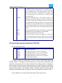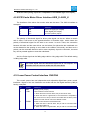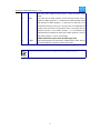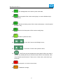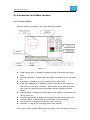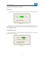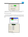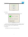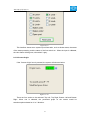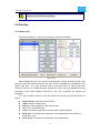
1
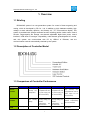
User’s Manual of RDC644XG Control System Shenzhen Reader Technology Co., Ltd. RD Co., Ltd. Shenzhen Reader Technology Co., Ltd Copyright Declaration Shenzhen Reader Technology Co., Ltd. reserves all rights. Shenzhen Reader Technology Co., Ltd. (hereinafter referred to as “RD Co., Ltd.”) holds the patent right, copyright and other intellectual property rights for this product and its related software. Without authorization, no one is allowed to copy, manufacture, process and use this product and its relative parts directly or indirectly. RD Co., Ltd. is entitled to increase or reduce and modify the shape and functions of this product stated herein as well as amend any documents attached to this product, without prior notification. The users should peruse this Manual prior to using the product stated herein. RD Co., Ltd. shall not be responsible for the direct, indirect, special, incidental or corresponding losses or damages arising out of improper use hereof or of this product. The machine in operation is dangerous, so the users are obliged to design and institute the effective mechanism for error handling and safety protection. RD Co., Ltd. shall not undertake any duties or responsibilities for the incidental or corresponding losses arising therefrom. II Version History V1.1:The original version V1.2: 1. The sixth pins definition of CN3 and CN4 is changed; 2. The fifth pins definition of CN5 and CN5 is changed; 3. Some explanation of the user parameters is changed; 4. Some of the Object Pictures of MainBoard silk-screen is changed; Shenzhen Reader Technology Co., Ltd CONTENTS 1. OVERVIEW..........................................................................................................................................1 1.1 BRIEFING.......................................................................................................................................... 1 1.2 DESCRIPTION OF CONTROLLER MODEL........................................................................................... 1 1.3 COMPARISON OF CONTROLLER PERFORMANCE............................................................................... 1 2 INSTALLATION SIZE......................................................................................................................... 4 2.1 INSTALLATION SIZE OF MAINBOARD............................................................................................... 4 2.2 SIZE OF PANEL..................................................................................................................................5 3 OBJECT PICTURES AND INTERFACES...................................................................................... 6 3.1 OBJECT PICTURES OF MAINBOARD................................................................................................. 6 3.2 OBJECT PICTURES OF PANEL............................................................................................................ 7 3.3 ELECTRIC CONNECTION....................................................................................................................8 4 DESCRIPTION OF INTERFACE SIGNAL FOR MAINBOARD...................................................9 4.1 INTERFACE OF MAIN POWER SOURCE CN0..................................................................................... 9 4.2 PANEL SIGNAL-CABLE INTERFACE HMI.......................................................................................... 9 4.3 UDISK INTERFACE............................................................................................................................ 9 4.4 PC-USB INTERFACE.........................................................................................................................9 4.5 ETHERNET INTERFACE......................................................................................................................9 4.6 GENERAL OUTPUT PORT CN1........................................................................................................10 4.7 GENERAL INPUT PORT CN2........................................................................................................... 10 4.8 4-AXLE SPACING INPUT INTERFACE CN3/CN4.............................................................................. 11 4.9 X/Y/Z/U AXLE MOTOR DRIVER INTERFACE AXIS_X~AXIS_U...................................................12 4.10 LASER POWER CONTROL INTERFACE CN5/CN6..........................................................................12 5 EXAMPLES OF LASER POWER INTERFACE...........................................................................14 5.1 BRIEF..............................................................................................................................................14 5.2 EXAMPLES OF GLASS TUBE LASER POWER................................................................................... 15 5.3 EXAMPLES OF RF-LASER............................................................................................................... 16 6 EXAMPLES OF DRIVER INTERFACE FOR STEP-SERVO MOTOR..................................... 17 6.1 BRIEF..............................................................................................................................................17 6.2 EXAMPLES OF MOTOR DRIVER CONNECTION................................................................................18 7 EXAMPLES OF IO-PORT WIRING................................................................................................19 7.1 INPUT..............................................................................................................................................19 7.2 OUTPUT.......................................................................................................................................... 20 8 OPERATING INSTRUCTION OF PANEL..................................................................................... 21 8.1 INTRODUCTION TO THE PANEL AND KEYS..................................................................................... 21 8.1.1 The whole panel..................................................................................................................21 II Shenzhen Reader Technology Co., Ltd 8.1.2 Introduction to the Keys..................................................................................................... 21 8.2 INTRODUCTION TO THE MAIN INTERFACE......................................................................................23 8.2.1 The main interface.............................................................................................................. 23 8.2.2 Speed key............................................................................................................................ 24 8.2.3 Max/Min power keys...........................................................................................................24 8.2.4 Set the layer parameters................................................................................................... 25 8.3 Z/U KEY.........................................................................................................................................26 8.3.1 Z move..................................................................................................................................26 8.3.2 U move................................................................................................................................. 26 8.3.3 Axis reset+........................................................................................................................... 26 8.3.4 Manual set+......................................................................................................................... 27 8.3.5 Laser set+............................................................................................................................ 28 8.3.6 Origin set+............................................................................................................................28 8.3.7 Set Fact Para.......................................................................................................................29 8.3.8 Def Fact Para...................................................................................................................... 30 8.3.9 Auto Focus........................................................................................................................... 30 8.3.10 Language........................................................................................................................... 30 8.3.11 IP Setup..............................................................................................................................31 8.3.12 Diagnoses.......................................................................................................................... 31 8.3.13 Screen Origin.................................................................................................................... 32 8.4 FILE KEY........................................................................................................................................33 8.4.1 Memory File......................................................................................................................... 33 8.4.2 U Disk File............................................................................................................................34 8.5 INTRODUCTION TO SOME ALARM INFO...........................................................................................35 9 MANUFACTURER/USER PARAMETERS EXPLANATION......................................................37 9.1 MANUFACTURER PARAMETERS.......................................................................................................37 9.2 USER PARAMETERS.........................................................................................................................40 III Shenzhen Reader Technology Co., Ltd 1. Overview 1.1 Briefing RDC644XG system is a new generation system for control of laser engraving and cutting, which is developed by RD Co., Ltd. In addition to high hardware stability, high voltage or static electricity rejection, and friendly 3.5’’ TFT man-machine display. This system is provided with stronger software function including perfect 4-axle motion control function, large-capacity file storage, two-channel adjustable digits laser power control interface, USB driver of stronger compatibility, multi-channel general/special IO control, and, this system can communicate with PC by USB2.0 or Ethernet, and the communication mode is automatically checked by the system. 1.2 Description of Controller Model 1.3 Comparison of Controller Performance Power Feature RDLC420 RDC6332G RDC6342G One-way 5V, one-way 24V, independent Only one-way 24V (compatible with 36V for power supply, but not recommended) Only one-way 24V (compatible with 36V for power supply, but not recommended) RDC644XG Only one-way 24V (compatible with 36V for power supply, but not recommended) Laser Port Feature USB Copying One-way digit and one-way analog Two-way digits and two-way analog port, settable independently and non-interacted Two-way digits and two-way analog port, settable independently and non-interacted Two-way Common Quick Quick Very Quick 1 settable digits port, independently and non-interacted Shenzhen Reader Technology Co., Ltd Feature Speed Compatibility Support USB disks with small capacity Support all USB disks with different capacities Support all USB disks with different capacities Support all USB disks with different capacities Memory Capacity 64M 256M 256M 128M Feature Fault Tolerance Common Capable of checking defective track and formatting and good in fault tolerance Capable of checking defective track and formatting and good in fault tolerance Capable of checking defective track and formatting and good in fault tolerance General IO Input Port Two ways 4 ways (two general, two specialties) 4 ways (two general, two specialties) 4 ways (two for general, Feature Output Port 1-way (low current, so additional drive is needed) for for 4-ways (500mA high current for each, OC output, no reverse current protection) for for 4-ways (500mA high current for each, OC output, no reverse current protection) two for specialties) 4-ways (500mA high current for each, OC output, reverse current protection included) Software Feature Display Feature Power-off restart for Engraving YES YES YES YES Multi-origin Logics NO YES YES YES Parameter Backup Logics NO YES YES YES Work Preview NO YES (the work time accurate to 1ms) YES (the work time accurate to 1ms) YES time (the work time accurate to 1ms) Online Update Mainboard Program NO YES YES YES Online Modification Laser Power/Speed YES YES YES YES Offline Modification Layer parameters NO YES YES YES Online Update Startup Display NO YES YES NO File dynamic/static preview NO YES YES YES Run progress bar display NO NO NO YES Modification Factory/User’s para on display NO YES YES NO Display type 128*64, display 320*240 TFT display 320*240 TFT display 320*480 TFT display Soft Spacing YES YES YES YES dot 2 Shenzhen Reader Technology Co., Ltd Motion-axl Hard Spacing NO YES YES YES e Feature Z-axle Linkage NO YES YES YES Feeding Feature Single direction Single/double direction for option Single/double direction for option Single/double Power-on Resetting Fixed Configurable each axes Configurable for each axes Configurable for each Key Speed Fixed Configurable Configurable Configurable Axles 4 3 (Z axes is configurable to flat or feedin axes) 3 (Z axes is configurable to flat or feedin axes) 4 Encryption based on the PC time Realtime clock and battery integrated for hardware encryption Realtime clock and battery integrated for hardware encryption No realtime clock, but USB2.0 10/100MHZ Ethernet or USB2.0 10/100MHZ Ethernet or USB2.0 10/100MHZ Ethernet or Encryption Feature Communic ate Mode for direction for option axes encryption included USB2.0, communication mode is automatically checked 3 Shenzhen Reader Technology Co., Ltd 2 Installation Size 2.1 Installation Size of MainBoard The unit of all sizes is millimeter (mm) and the size accurate to 0.1mm (the four holes are symmetrical) Figure 2.1-1 4 Shenzhen Reader Technology Co., Ltd 2.2 Size of Panel The unit of all sizes is millimeter (mm) and the size accurate to 0.1mm. Figure 2.2-1 5 Shenzhen Reader Technology Co., Ltd 3 Object Pictures and Interfaces 3.1 Object Pictures of MainBoard For more detailed pin description, see the Chapter 4: Description of Interface Signal for MainBoard. Figure: 3.1-1 Object Picture of MainBoard 6 Shenzhen Reader Technology Co., Ltd 3.2 Object Pictures of Panel Figure: 3.2-1 Object Picture of Panel 7 Shenzhen Reader Technology Co., Ltd 3.3 Electric connection Figure 3.3-1 electric connection 8 Shenzhen Reader Technology Co., Ltd 4 Description of Interface Signal for MainBoard 4.1 Interface of Main Power Source CN0 Pin Symbols Definitions 1 GND 24V power ground (input) 2 +24V 24V power positive (input) This control system employs single 24 power supply. For a certain margin, it is suggested to select 24V/2A power. Besides, this system is Caution compatible with 36V power, that is to say, the 36V power of Motion driver can directly be connected to this main power port of this system, but generally it is not suggested to do so. 4.2 Panel Signal-Cable Interface HMI The panel signal-cable is a pin-to-pin cable, which is included in the factory shipper bill. 4.3 Udisk Interface Udisk is a USB-AM interface. The controller may visit the u-disk by this interface. 4.4 PC-USB Interface PC-USB is a USB-BM interface. The controller may communicate with PC by this port. 4.5 Ethernet Interface Using this interface, the mainboard can communicate with PC by 10/100MHZ Ethernet. 9 Shenzhen Reader Technology Co., Ltd Pin to Pin Ethernet parallel line is recommended. Caution 4.6 General Output Port CN1 Definition of general output port Pin Symbols Definitions 1 2 3 4 GND Out2 Out1 Status Power ground (output) General output, with the function reserved. General output, with the function reserved. General output for the signal port of running status. If this port is externally connected with the relay, the relay coil is broken over when it works; no influence is produced when it suspends working. When its work ends or is stopped manually, the relay coil will be 5 Wind 6 +24V cut off. General output for blower control. When the blower control is enabled, this port will output the control signal of the blower, otherwise it will output other special control signals. When the blower is connected and its control enabled, the blower switch can be set separately on each layer. If the relay is connected externally, the relay coil will be broken over when the blower is on; the relay coil will be cut off when the blower is off. 24V Power positive output (If the interface of main power source is powered with 24V power supply, this pin should be 24V; if it is powered with 36 V power supply, this pin should be 36V.) All outputs are isolated through the optocoupler, and 500mA current for each, OC gate output, each can directly drive the 6V/24V relay. Prompt 4.7 General Input Port CN2 Pin Symbols Definitions 1 2 GND FootSW Power ground (output) Input port of foot switch. The connection method is: when the pedal is stepped down, the low-level signal will be inputted to this port; when the pedal is released, the port will be disconnected or the high-level signal can be inputted to this port; when the stepped-down pedal is held for not less than 100 ms, if the machine lies idle, it can be started for work; if the machine is in the working state, the work will be suspended; of the machine is in the suspension, the work will 10 Shenzhen Reader Technology Co., Ltd be restarted, that is to say, the function of the pedal switch is the same as that of the “Start/Pause” key. If the interval time to the first stepping-down of the pedal should be less than 100ms when the pedal is stepped down once again, the second stepping-down of the pedal will be considered invalid by the mainboard. 3 DrProc Input from protective port. If the machine needs to be protected in the special state (such as door open protection), the protective signal can be inputted from this pin. This pin can be enabled and prohibited. This signal is not inquired by the mainboard if this pin is prohibited; if this pin is enabled, when the input is high-leveled or this input port is suspended, the machine will be protected, the work suspended and the laser closed. 4 Shot Input for manual laser on/off. Low level is to open laser and high level or no-connection is to close laser. 5 6 IN1 +24V General Input, with the function reserved. 24V Power positive output (If the interface of main power source is powered with 24V power supply, this pin should be 24V; if it is powered with 36 V power supply, this pin should be 36V.) 4.8 4-axle Spacing Input Interface CN3/CN4 X/Y axle spacing input CN4 Pin Symbols Definitions 1 2 3 4 5 6 GND LmtYLmtY+ LmtXLmtX+ Puxy Power ground (output) The spacing from axle Y- and Y to 0 coordinate The spacing from axle Y+ and Y to max. coordinate The spacing from axle X- and X to 0 coordinate The spacing from axle X+ and X to max. coordinate 5V Power positive (output) The spacing polarity is optional, that is to say, when the motion axle reaches the spacing position, it will trigger a low-level signal so as to make the corresponding LED (under the cover) light; when the motion axle leaves the spacing position, it will trigger a high-level signal or disconnect the spacing signal so as to make the spacing indicator go out, but when it leaves the spacing, the corresponding indicator will light and the spacing polarity become positive. The mistaken setting of spacing polarity will result that the spacing can’t be detected when the system is reset so as to lead to the collision of axles. The pin definitions of Z/U axle spacing input CN3 are the same as CN4. 11 Shenzhen Reader Technology Co., Ltd All XYZU axle spacing inputs are compatible to 5V/12V/24V logic level inputs。 4.9 X/Y/Z/U axle Motor Driver Interface AXIS_X~AXIS_U The interfaces of the above four motion axles are the same. The AXIS-X interface is exampled. Pin Symbols Definitions 1 2 3 DIR PUL +5V Directional signal (OC output) Pulse signal (OC output) 5V Power positive (output) The polarity of directional signal for driver pulse signal can be set. Where a certain axle is reset, it will move to the opposite direction of machine origin, which means the polarity of directional signal for this axle is not correct. In such a case, the connection between this axle and the motor driver can be broken first (otherwise the mainboard can not be detected to the spacing so as to lead to the collision of this axle), and then such a polarity can be corrected after this axle is reset completely. Upon the correction, the reset key can be pressed against to reset the mainboard. And, the Pulse signal can be falling edge valid or rising edge valid. The default setting is falling edge valid. The Pulse signal and the directional signal are all OC outputs. The Controller must be common anode with the motor driver Prompt 4.10 Laser Power Control Interface CN5/CN6 This control system has two independent and adjustable digital laser power control interfaces. Signals of the two interfaces are similar and the first digital interface (CN5) is hereby exampled: Pin Symbols Definitions 1 2 GND L-ON1 Power ground (output) Laser-enabled control interface 1. When the laser is the RF laser, this pin will not be used; 2. When the laser is a glass tube, if the used laser is outputted in the low-level form, this pin will be connected with the laser power 3 LPWM1 enable end and used to control the ON/Off of laser. Power control interface of laser/laser tube 1. When the laser is the RF laser, this pin will be connected with the laser RF-PWM end; 2. When the laser is a glass tube, this pin will be connected with 12 Shenzhen Reader Technology Co., Ltd the laser power PWM end and used to control the power of the laser. 4 WP1 The input port of water protector for the first laser power source. When the water protector 1 is enabled, the mainboard will detect the input port of water protector 1. If this port is of low level, it will be deemed normal; if this port is of high level, the mainboard will forcibly close the laser to suspend the work in progress and the system will warn. If the water protector 1 is not enabled, the mainboard will not detect the input port of water protector 1 and so the water protector 1 can be unconnected. Water protection input must be 24V logic level. 5 L-AN1 The analog signals for Laser Power. If Glass Tube is used, this pin is recommended to control the power of the Laser. Please correctly select the laser type in the factory parameters. Prompt 13 Shenzhen Reader Technology Co., Ltd 5 Examples of Laser Power Interface 5.1 Brief This control system has two independent and adjustable digital laser power control interfaces, which can be used to control glass tube laser power and RF-laser. Please correctly select the laser type in the factory parameters, or, the laser control is incorrect. 14 Shenzhen Reader Technology Co., Ltd 5.2 Examples of Glass tube Laser Power 15 Shenzhen Reader Technology Co., Ltd 5.3 Examples of RF-Laser 16 Shenzhen Reader Technology Co., Ltd 6 Examples of Driver Interface for Step-servo Motor 6.1 Brief The input signal end of step-servo motor driver employs the light-coupled isolation technology. For the step-by-step impulse signal, some isolate the side OC diode from cutoff to conduction (e.g. the valid falling edge of pulse signal inputted from the diode minus end) and some do so from conduction to cutoff (e.g. the valid rising edge of pulse signal inputted from the diode minus end). When it is indicated whether the pulse signal of motor driver is the valid rising edge or the valid falling edge, it will be subject to the pulse signal inputted from the minus end of side OC diode. Some input signals of motor driver are independent and some are internally of common anode, so some have 4 external leading-out wires and some 3 wires (only the pulse and directional signals are counted) as shown in Figure 6.1-1 and 6.1-2. RDC644XG Controller has four groups of 3-wires motion driver interface, each interface has one direction signal, one pulse signal, and one 5V positive output, the direction signal and the pulse signal are all OC output. RDC644XG controller must be common anode with the motor driver. The polarity of the direction signal can be changed in the factory parameters, and the valid edge of the pulse signal can also be changed. Figure: 6.1-1 Four Inputs, Independent Input Signal of Driver Figure: 6.1-2 Three Inputs, Common-anode Input Signal of Driver 17 Shenzhen Reader Technology Co., Ltd 6.2 Examples of Motor Driver Connection 18 Shenzhen Reader Technology Co., Ltd 7 Examples of IO-port Wiring 7.1 Input The two water protection inputs are 24V logic level; all other inputs are compatible with 5V/12V/24V logic level. Input connection shown as below Figure 7.1-1 example of input 19 Shenzhen Reader Technology Co., Ltd 7.2 Output All outputs are isolated through the optocoupler, and 500mA current for each, OC gate output, each can directly drive the 6V/24V relay, led lamp, buzzer etc. Output connection shown as below Figure 7.2-1 example of output 20 深圳市睿达科技有限公司 8 Operating Instruction of Panel 8.1 Introduction to the Panel and Keys 8.1.1 The whole panel 8.1.2 Introduction to the Keys Reset :Reset the whole system; Origin :Set the relative origin; Laser Fram e :Let the Laser to splash; :To track by the current file’s frame; 21 深圳市睿达科技有限公司 File :The management of the memory and U disc files; Speed :Set the speed of the current running layer, or set the direction keys’ move speed; Max. Power :Set the max laser power of the current running layer, or set the power of “Laser” Key; Min. Power :Set the min laser power of the current running layer, Start/ Pause :To start or pause the work; :To move the X axes or the left/right cursor; :To move the Y axes or the up/down cursor; :The Z/U key can be pressed when the system is idle or the work is finished. On pressing this key, it will show some entries in the interface, each entry includes some functions, Z axes move, U axes move, each axes to go home etc.; Esc Enter “:To stop work, or to exit to some menu; : Validate the change; 22 深圳市睿达科技有限公司 8.2 Introduction to the Main Interface 8.2.1 The main interface When the system is powered on, the screen will show as below: Figure 8.2-1 Graph Display Area: To display the whole file’s track, and display the running track. Running parameters: To display the running file’s file number, speed, max power etc.; Coordinate: To display the current coordinate of X,Y and Z axes Graph layer parameters: To display the layers’ information of the current file, such as max or min power, speed etc.. When system is idle, dblclick the layer, then users can change the layer’s parameters and the changing would be saved. Running Status: To display the current status of the machine, such as Idle, Run, Pause, Finish, etc.; Running Progress Bar: To display the progress bar of the current running file; Working Number: To accumulate the work number of the current file. File Dimension: To display the dimension of the current file; Net status: To display the connecting status of the Ethernet. When work is Idle or finished, all keys can be pushed, users can select a file to run, 23 深圳市睿达科技有限公司 set some parameters, preview to a select file etc. But, when work is running or paused, some keys don’t respond when they are pushed. 8.2.2 Speed key Push the “Speed” key when the screen is on the main interface, it will show as below: Figure 8.2-2 Push the “X+/-“ Keys to move the cursor in the numeral area, and push the “Y+/-” keys to change the value, then push the “Enter” key to save the change, push the “Esc” key to invalidate the change. 8.2.3 Max/Min power keys Push the “Max Power” or the “Min Power” keys when the screen is on the main interface, it will show as below: Figure 8.2-3 24 深圳市睿达科技有限公司 Figure 8.2-4 When “Z/U” key is pushed, the green block can move up and down to denote the changing item, then “Y+/-” keys and “X+/-” keys can be used to change the value. 8.2.4 Set the layer parameters After selecting a file to preview on the main interface, user can push “Enter” key to let the cursor move to the first layer, then “Y+/-” Keys can be pushed to select the intent layer, on that time, user can push “Enter” key to check the selected layer’s parameters, show as below: Figure 8.2-5 Figure 8.2-6 25 深圳市睿达科技有限公司 User can push “Z/U” Keys to move the green block on the intent parameter, then he could change the parameter if needed. “OK” to validate the change, and “Esc” to invalidate the change. 8.3 Z/U Key The Z/U key can be pressed when the system is idle or the work is finished. On pressing this key, it will show some entries in the following interface: Figure 8.3-1 Push “Y+/-” keys to move the green block to the anticipant item, and then push the “Enter” key to display the sub menu. 8.3.1 Z move When the green block is on “Z Move” item, “X+/-” keys can be used to move the z axes. 8.3.2 U move When the green block is on “U Move” item, “X+/-” keys can be used to move the u axes. 8.3.3 Axis reset+ When the green block is on this item, push the “Enter” key to show as below: 26 深圳市睿达科技有限公司 Figure 8.3-2 Push the “Y+/-“ Keys to move the cursor to one of the entry, then push “Enter” key to restart the selected axis, the screen will show some information when resetting. 8.3.4 Manual set+ When the green block is on this item, push the “Enter” key to show as below: Figure 8.3-3 Push “Z/U” key to move the green block, and when the green block is on the “Mode” item, push “X+-“ keys to select the anticipant value, “Continue” or “Manual”. When “Continue” item is selected, then the “Manual” item is not valid, on that time, push the direction keys to move the corresponding axes, and when the pushed key is loosed, then the corresponding axes will finish moving. When the Mode item is “manual”, then pushing the direction key one time, the corresponding axes will move a fixed length, unless the scope is overstepped. 27 深圳市睿达科技有限公司 8.3.5 Laser set+ When the green block is on this item, push the “Enter” key to show as below: Figure 8.3-4 Push “Z/U” key to move the green block, and when the green block is on the “Mode” item, push “X+-“ keys to select the anticipant value, “Continue” or “Manual”. When “Continue” item is selected, then the “Laser Set” item is not valid, on that time, push the Laser key to splash the enabled lasers, and when Laser key is loosed, then the lasers will finish splashing. When the Mode item is “manual”, then pushing the Laser key one time, the enabled lasers will splash a fixed time. 8.3.6 Origin set+ When the green block is on this item, push the “Enter” key to show as below: Figure 8.3-5 28 深圳市睿达科技有限公司 Push “Z/U” key to move the green block to the anticipant item, and when the green block is on “enable” items, push “Enter” key to enable or disable the item, when enabled, the small diamonds is green, and when disabled, the small diamonds is grey. When the green block is on the “Set origin” item or the “Next origin” item, push the “X+-“ keys to select the value. Pay attention to if when the green block is on the “Set origin” item, push the “X+-“ keys to select a value, then, “Enter” key must be pushed to valid the change, or, the change is invalid. Each item introduced as below: Multiple Origins Enable: “Yes” or “No” can be selected. If you select “No”, the system will use the single-origin logic. You can press the “Origin” key and set the origin, and only this origin can become valid. If you select “Yes”, the system will use the multiple- origin logic and the “Origin” key on the keyboard become invalid. In such a case, the parameter of each origin must be set in the menu as follows. Origin Enable1/2/3/4: after the multiple-origin logic is enabled, the four origins can independently be prohibited and enabled. Set Origin 1/2/3/4: after the multiple- origin logic is enabled, you can stop the cursor at “Set as Origin 1/2/3/4”. Press the “Enter” key on the keyboard and the system will take the coordinate figures of current X/Y axles as the corresponding ones to the origin 1/2/3/4. Next Origin: there are such five digits as 0~4 for option, which are the origins to be used for the next figure. Origin 0 means the origin set by the “Origin” key on the panel in the single- origin logic. 1~4 means the serial number of the origins in the multiple- origin logic. Next origin can be modified to any one of origin 1~4, so as to control the start location of next work (the premise is that the origin is enabled), but it can’t be modified to origin 0. Prompt Once the multiple- origin logic is selected and if the serial number of the next origin is 1 and four origins are enabled, when the memory file function is started or the processing file is uploaded into the PC and this file selects “Take the Original Origin as current Origin”, the work started for each time will use different origins. The rotation order of origin is 1->2->3->4->1->2……. 8.3.7 Set Fact Para After the “Set Fact Para” is selected and the Enter key pressed, the interface will show the specific password to be entered when set as default parameter. 29 深圳市睿达科技有限公司 Figure 8.3-6 Push “X+/-” keys and “Y+/-” keys to select the characters, and push the “Enter” key to valid the characters, when finishing enter the password ,that is to say, the six characters, if the password is error, it prompts there is some error, or, all parameters are stored. Prompt After the manufacturer regulates all parameters of the machine well (including all manufacturer parameters and user parameters), this function can be used to store the well-regulated parameters to help users to recover the original parameters (including all manufacturer parameters and user parameters) through selecting “Recover Para” when they regulate parameters improperly. 8.3.8 Def Fact Para After the “Def Fact Para” is selected and the Enter key pressed, the “Successful Recovery” dialog box will pop up to prompt that all manufacturer parameters and user parameters are recovered successfully. You can return to the previous menu by press the Enter key. 8.3.9 Auto Focus When the cursor stops at “Auto Focus”, press the Enter key to search for the focus(When there is z axes, and the z axes reset function is enabled, the auto focusing is valid); press the Esc key to return the prior menu. 8.3.10 Language The item “Language” helps you to select a appropriate langue which is displayed on the pane: 30 深圳市睿达科技有限公司 Figure 8.3-7 8.3.11 IP Setup When the green block is on this item, push the “Enter” key to show as below: Figure 8.3-8 Push “Z/U” key to move the changing item, then push “X+/-” keys and “Y+/-” keys to change the value, when all the IP value and the Gateway value are changed, push “Enter” key to validate the change, or “Esc” key to invalidate the change. 8.3.12 Diagnoses If the “Diagnoses” item is pressed, the system will show as below: 31 深圳市睿达科技有限公司 Figure 8.3-9 This interface shows some system input information, such as limiter status, the status of the water protecting, and the status of the foot switch etc.. When the input is validated, the color frame will be green, otherwise it’s gray. 8.3.13 Screen Origin If the “Screen Origin” item is pressed, the system will show as below: Figure 8.3-10 There are four entries to be selected: Top Left, Top Right, Bottom Left and Bottom Right. When one is selected, the previewed graph on the screen would be enantiomorphous based on X or Y direction. 32 深圳市睿达科技有限公司 This item is only used to preview the file on the screen, and it is no meaning to the machine’s movement. Caution 8.4 File Key 8.4.1 Memory File On the main interface, if “File” key is pressed, it will show as below: Figure 8.4-1 When showing this menu, the system would read the memory file firstly, the file name and the work times would be listed in the area, and the selected file is previewed in the bottom right area. “Y+/-” keys could be used to move the cursor on the file name list. When the cursor is on a target file name, presses the “Enter” key, the selected file will be previewed on the main interface, and then if “Esc” key is pushed, the preview will disappear. “X+/-” keys could be used to move the cursor left and right. All the item show as below: Read mem file: read the memory file list; Udisk: read the U disk file list; Other: the other operation of the memory files; Run: To run the selected file; Track: To track the selected file, and the track mode is optional; Work time: To forecast the running time of the selected file, and the time is accurate to 1ms; Clear count: To clear the running times of the selected file; 33 深圳市睿达科技有限公司 Delete: To delete the selected file in the memory; Copy to Udisk: To copy the selected file to Udisk; If the “Other” entry is pressed, the system will show as below: Figure 8.4-2 Current work time: To forecast the running time of the current file(the current file No. is showed on the main interface), and the time is accurate to 1ms. Clear all count: To clear the running times of every file in the memory Delete all file: To delete all memory files Format speedily: To format memory speedily, and then all the files in memory will be deleted. Format drastically: To format memory drastically, and then all the files in memory will be deleted. Total: the total running times of all the files. 8.4.2 U Disk File If the “Udisk” entry in figure 8.4-1 is pressed, the system will show as figure 8.4-3, and the operation method is all the same as figure 8.4-1. 34 深圳市睿达科技有限公司 Figure 8.4-3 Read Udisk: read the file list in the Udisk; Copy to memory: copy the target Udisk file to the memory; Delete: delete the selected Udisk file; Prompt This system supports such file formats of Udisk as FAT32 and FAT16, but it can identify them when the files are put under the root directory of Udisk. The file name of more than 8 characters will automatically be cut out by the system. The file name that has only English letters and digits will not show when they are copied to the mainboard. The files copied from the mainboard to Udisk will be placed under the root directory of Udisk. 8.5 Introduction to some alarm info When users are operating the system, or when the machine is running, some alarm information such as water protecting error maybe shows as below: 35 深圳市睿达科技有限公司 Figure 8.5-1 Push “Enter” key or “Esc” key, the system will execute some relative steps. 36 深圳市睿达科技有限公司 9 Manufacturer/User Parameters Explanation 9.1 Manufacturer parameters (1)Motor parameters X/Y/Z/U axle parameters Direction Polarity: Modification of direction polarity can move the motor to the opposite direction. The modification purpose can move this axle to the origin on resetting. If this axle moves far from the origin on resetting, it means the direction polarity of this axle is wrong in setting and should be modified. Spacing Polarity: it is used to set the high and low level mode of spacing signal. When the motion axle arrives at the spacing position and input a low-level signal to the mainboard, the spacing polarity at this time should be set to be minus. scope: it means the farthest distance that the motion axle can move, which is determined in accordance with the actual condition of the machine. Distance from Origin to Hard Spacing: if this axle enables hard-spacing protection, generally this value should be set to be 2~5mm; if it is set to be 0, when this motion axle moves to the smallest coordinate, i.e. 0, this spacing may be validate, which may wrongly triggers the hard-spacing protection and scram the machine. If the hard-spacing protection is not enabled, this value can be set to be 0~5mm. Control Mode: Double pulse or direction+single pulse are optional, in general, direction+single pulse is selected. Motor Stepping: it means the impulse equivalent, the absolute distance gone by the corresponding motion axle when a pulse is delivered to the motor. Prior to the correct setting of this value, a large rectangle can be cut with the machine (the larger the figure is, the smaller the difference is). The motor stepping can automatically be calculated according to the figure length and measuring length. Hard-spacing Protection: it is used for whether the hard-spacing protection of this axle is enabled. PWM Rising edge valid:To set the motor driver’s pulse signal rising edge valid or falling edge valid. If this item is disabled, the pulse is falling edge valid, or, it’s rising edge valid. Reset Enable: if the machine is provided with this axle, its “Reset Enable” should be opened; if no, its “Reset Enable” should be prohibited. Takeoff Speed: it means the speed of the motion axle in direct start from the idle condition. If this value is excessively large, it will make the motor lose steps, jar and even squeak; if small, it will reduce the running speed of the whole figure. If the inertia of the motion axle is larger (the axle is heavier), you can set a smaller 37 深圳市睿达科技有限公司 takeoff speed; if smaller (the axle is lighter), you can increase the takeoff speed. For example, the typical value is 5~30mm/s. Maximum Speed: it means the maximum limit of motion speed that this axle can bear. This parameter has something to do with the driving force of motor, the inertia of motion axle and its drive ratio. For example, the typical value is 200~500mm/s. Maximum Acceleration: it means the maximum acceleration of the motion axle in accelerated or decelerated motion. If the acceleration is set too large, it will make the motor lose steps, jar and even squeak; if too small, it will cause the reduction of acceleration so as to reduce the running speed of the whole figure. For the axles with larger inertia, such as Y axle corresponding to the beam, its typical setting range is 800~3000mm/s2; for the axles with smaller inertia, such as X axle corresponding to the car, its typical setting range is 8000~20000mm/s2. Scram Acceleration: if this axle enables the hard-spacing protection, when this axle moves to the spacing position, it will scram operation at the scram acceleration. This value can be 2~3 times of the maximum acceleration for this axle. Key parameters Key Move Takeoff Speed: it means the starting speed to move this axle by way of the keys on the keyboard, which can’t be higher than the takeoff speed. Key Move Acceleration: it means the acceleration to move this axle by way of the keys on the keyboard, which can’t be higher than the maximum acceleration of this axle. Key Polarity: it is used to control the movement direction of the axle that is moved through manual operation of the keys. After the direction polarity is correctly set, if you press the directional keys on the operating panel, this axle will move to the opposite direction. In such a case the polarity of keys should be modified. (2)Laser parameters Laser Configuration: single laser and double lasers are available for option and set in accordance with the laser-tube quantity provided by the manufacturer. Laser Type: glass tube, RF laser (not need pre-ignition pulse) and RF laser (needing pre-ignition pulse) available for option. Laser Attenuation Quotiety Laser Enable: When double lasers are used, then each laser can be respectively enabled or disabled. Minimum Power Maximum Power Laser PWM Frequency Pre-generation Frequency 38 深圳市睿达科技有限公司 Pre-generation pulse scale: When the laser is RF-laser and it’s need to pre-generate PWM, then set the Pre-generation Frequency and the Pre-generation pulse scale. Water Protector Enabled: When the water protector is enabled, the mainboard will detect the input port of water protector. If this port is of low level, it will be deemed normal; if this port is of high level, the mainboard will forcibly close the laser to suspend the work in progress and the system will warn. If the water protector is not enabled, the mainboard will not detect the input port of water protector and so the water protector can be unconnected. Laser PWM Frequency is used to set the pulse frequency of control signal used by this laser, in general, glass tube is about 20KHZ, RF laser is about 5KHZ; the maximum/minimum power (%) is used to set the limit power of this laser, that is to say, during the operation, the maximum power set by the user can’t be higher than that set here and the minimum power set by the user can’t be less than that set here, either. When a laser’s power is attenuated, then the laser attenuation quotiety may be set If it is only provided with the single laser, it can show the one-path parameter. Prompt (3)Other manufacturer parameters Machine configuration Machine Type: In most cases, the general engraving machine should be selected and other types used for specific purposes. Transmission Mode: generally the “Belt Stepping Type” should be made choice of. The control algorithm will be changed a little when other types are selected. Feeding Mode: it has single-way mode and two-way mode for option. If it is of single-way feeding, it is unnecessary to check the coordinates. Feeding can be conducted in the single-way mode; if it is of two-way feeding, the system will check the maximum and minimum coordinates. The odd sequence means feeding should be done to one direction and the even sequence means feeding done to the other direction. The initial direction for the first time can be changed through setting the directional polarity or modifying the plus and minus values of the feeding length. Power-Off-Restart Delay: it can be set to be 0~3000ms. After the power-off of the electricity grid, the power supply of the system will not drop to 0 at once. There is a delay during this time. The delay value set here should basically consistent with the actual off-delay value. If the deviation of set value is larger, on the de-energizing for continuous engraving, either the figure processed for the second time is not closed with that before the cutoff, or it is coincided with that too much. 39 深圳市睿达科技有限公司 Prompt After the configuration parameters in the manufacturer parameters, such as directional polarity, control mode, laser type and laser PWM frequency, are modified, the system should be reset. Such a modification can function upon the resetting of the system. Enable parameters Door Opening Protection: If this item is enabled, then the door opening protection must be connected to the controller, or, the machine will not run. Whether to enable the blower: If using wind out port to control the blower by the graph layer parameter, this item must be enabled, or, the wind output is a signal for other using. 9.2 User parameters (1)Cutting parameters(Only affect cutting arts) Idle Move Speed: this parameter decides the highest speed of all non-lighting lines for the machine in the movement process. Idle Move Acceleration: it means the highest acceleration of all non-lighting lines. Idle stroke speed and idle stroke acceleration can be set higher to reduce the working time of the whole figure, but if they are set too high, it may cause the jarring of track, so comprehensive consideration should be given to the setting. Idle Move Delay : If this parameter is zero, then after idle moving there is no delay, or, there is delay and the speed will decrease to turn off speed. Turning Speed: it means the speed of turning at the acute-angle corner, which is also the highest speed in the whole cutting process. Turning Acceleration: it means the acceleration of turning at the acute-angle corner when cutting. If the two speeds are set too high, jarring will happen to the turning; if set too low, it will influence the cutting speed. This acceleration is the least value of the whole graph. Cutting Acceleration: it means the highest acceleration value in the whole cutting process. Acc Factor: This parameter indicates how speedy the cutting acceleration is changing. G0 Acc Factor: This parameter indicates how speedy the idle move acceleration is changing. Speed Factor: This parameter indicates the cutting speed of the arc of various curvatures. ● Key Setting: This is a button but not a parameter, this button is used to recommend some experiential cutting parameters. (2)Scanning parameters(Only affect scanning arts) 40 深圳市睿达科技有限公司 X-axle Starting Speed Y-axle Starting Speed X-axle Acceleration Y-axle Acceleration The above four parameters are used to set the starting speed and acceleration of two axles on the scanning. The higher the two speeds are, the quicker the scanning is. Scanning Line-feed Speed: this parameter is specially used to control the highest speed at which that the previous line vertically moves to the next line in the scanning mode. If the space between lines is larger during the scanning or if the distance of each block is larger during the scanning and deblocking of figure, it is necessary to position each line or block accurately. In such a case the speed of scanning line-feed can be set as a lower value. Scanning Mode: it is divided into general mode and special mode for option. If special mode is used, the laser power should be increased. The smaller the speckle percentage is, the more the laser power reduces. The laser power to set should be larger in order to reach the same scanning depth. The purpose to select the special mode is to make the laser light at high power and short time. On the depth scanning the effect that the bottom is flatter is obtained, but it should be noticeable that if the speckle adjustment is not appropriate, it can achieve this goal. If the high power remains short, the lighting mode will influence the life of the laser. The system will default the selection of general mode. Speckle Size: When the general mode is selected as the scanning mode, this parameter will become ineffective; when the special mode is selected, this parameter will become effective. The controller will control this parameter among 50%~99%. Prompt The cutting and scanning parameters can’t exceed the limited ones in the axle parameters. If so, the setting will become ineffective and the system will automatically cover the parameters with the axle parameters. (3)Feeding parameters Before-feeding Time Lag: settable at 0~300s. The lagged time can facilitate user’s feeding and picking on the feeding device. After-feeding Time Lag: settable at 0~9.9s. It can facilitate the feeding device’s delaying in jarring after moving to the correct position and waiting for the 2nd work after the feeding axle stands still completely. Progressive feeding: If this item is enabled, then the dummy array graph on Y direction will run in the same position, running one line graph, the U axes moving one time to feed, the moving length of U axes is the interval of the two lines graph on Y direction. Progressive feeding repay: Because of the imprecision of U axes’ moving, there can set a value to repay the interval of the two lines graph on Y direction. 41 深圳市睿达科技有限公司 (4)Reset parameters Reset Speed: it means the speed of X/Y-axle linkage reset to the origin. X axle start-up reset(Auto home) Y axle start-up reset(Auto home) Z axle start-up reset(Auto home) U axle start-up reset(Auto home) You can select “Yes” or “No” in the field of the above four parameters, which is used to confirm whether each axle can be reset on the startup. (4)Go scale parameters Go scale Mode: “Blanked Bordering” means idling to start border preview; “Outputted Border Cutting” can manually cut off the well-processed figure; “4-corner Dotting” means to emit the light at four corner points of the frame to make a point and turn off light. The size and position of this figure can be checked intuitively through the four points. The bordering speed is the speed value set on the keyboard when the system is idle. For light output, its minimum/maximum power is the corresponding value set on the keyboard when the system is idle (The lasering power on the 4-corner dotting means the well-set maximum power). Go scale Blank: It means whether to extend a certain length outside the actual frame of the figure on the preview/cutting of frame. Prompt If the frame crosses the border, the interface will prompt it. If the Enter key is pressed at this time, the system will cut the border at the maximum/minimum coordinates first, and then border the figure. This bordering can be given up. (5)Other user parameters Array Mode: Two-way array or one-way array can be selected. Two-way array means the to-and-fro cutting of array in sequence; one-way array means the cutting of array from one direction to another. On selecting one-way array, the elements of each array are the same in action mode and completely uniform in action fluency, which takes a little more time than two-way array. Two-way array is the default option. Back Position: The origin (the relative origin) and the machine’s absolute origin can be selected. This parameter decides the parking position of laser head after each work. Focus Setting: it means the distance from the focal point of laser head lens to Z-axle origin. When there is no automatic focusing function, this parameter becomes invalid. Backlash X: The X axes’ backlash, accurate to 1um. Backlash Y: The Y axes’ backlash, accurate to 1um. 42 深圳市睿达科技有限公司 10 controller to PC with single NIC Single controller to PC with single NIC STEP 1: Set the work mode to be ETHERNET on the panel. And then set the controller IP address between 192.168.001.100-192.168.001.149 STEP 2: Set the IP address in the PC. The IP address is between 192.168.001.2-192.168.001.049. Reference to picture1-1 Picture1-1 PC IP configuration Single controller to PC with multi-NIC STEP 1: Set the first NIC IP. The same as the single NIC above. 43 Single controller to PC with 深圳市睿达科技有限公司 STEP 2: The second NIC may be connected to internet with router. So the router should be configured. First. (1) Open IE and input the IP address 192.168.1.1(just for most NIC). And then enter the NIC configuration interface. Then input the password (default is Admin) Set the router IP address to be 192.168.2.1(make sure the IP to difference with other routers) (2) Get the router DNS Record the DNS server. (3) Configure the second NIC IP address and DNS server. Seen as follows. 44 深圳市睿达科技有限公司 PC and Multi-controller to concentrator. 1 PC connects the input of the concentrator. Multi-controller connects to the output of the concentrator. 2 Different IP address should be configured for every controller. But all of the IP address should be set between 192.168.001.100-192.168.001.149 3 Then set the PC IP address between 192.168.001.2-192.168.001.049. PC and Multi-controller to concentrator. And the 45 深圳市睿达科技有限公司 concentrator connects to router. 1 2 PC and multi-controller connect to output on the concentrator. Different IP address should be configured for every controller. But all of the IP address should be set 3 between 192.168.001.100-192.168.001.149 Configured step please reference to multi-NIC 46 Single controller to PC with