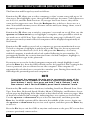
1
DECEMBER 2005
KV9204A
KV9208A
KV9216A
4-, 8-, and 16-Port ServSwitch
EC Series PS/2 and USB (User/CPU)
KVM Switch
CUSTOMER
SUPPORT
INFORMATION
Order toll-free in the U.S.: Call 877-877-BBOX (outside U.S. call 724-746-5500)
FREE technical support 24 hours a day, 7 days a week: Call 724-746-5500 or fax 724-746-0746
Mailing address: Black Box Corporation, 1000 Park Drive, Lawrence, PA 15055-1018
Web site: www.blackbox.com • E-mail: [email protected]
FCC AND IC RFI STATEMENTS
FEDERAL COMMUNICATIONS COMMISSION
and INDUSTRY CANADA
RADIO FREQUENCY INTERFERENCE STATEMENTS
Class B Digital Device. This equipment has been tested and found to comply with
the limits for a Class B computing device pursuant to Part 15 of the FCC Rules.
These limits are designed to provide reasonable protection against harmful
interference in a residential installation. However, there is no guarantee that
interference will not occur in a particular installation. This equipment generates,
uses, and can radiate radio frequency energy, and, if not installed and used in
accordance with the instructions, may cause harmful interference to radio
communications. If this equipment does cause harmful interference to radio or
telephone reception, which can be determined by turning the equipment off and
on, the user is encouraged to try to correct the interference by one of the following
measures:
• Reorient or relocate the receiving antenna.
• Increase the separation between the equipment and receiver.
• Connect the equipment into an outlet on a circuit different from that to which
the receiver is connected.
• Consult an experienced radio/TV technician for help.
CAUTION
Changes or modifications not expressly approved by the party
responsible for compliance could void the user’s authority to operate
the equipment.
To meet FCC requirements, shielded cables and power cords are required to
connect this device to a personal computer or other Class B certified device.
This digital apparatus does not exceed the Class B limits for radio noise emission from digital
apparatus set out in the Radio Interference Regulation of Industry Canada.
Le présent appareil numérique n’émet pas de bruits radioélectriques dépassant les limites
applicables aux appareils numériques de classe B prescrites dans le Règlement sur le brouillage
radioélectrique publié par Industrie Canada.
1
SERVSWITCH EC SERIES PS/2 AND USB (USER/CPU) KVM SWITCH
NORMAS OFICIALES MEXICANAS (NOM)
ELECTRICAL SAFETY STATEMENT
INSTRUCCIONES DE SEGURIDAD
1. Todas las instrucciones de seguridad y operación deberán ser leídas antes de
que el aparato eléctrico sea operado.
2. Las instrucciones de seguridad y operación deberán ser guardadas para
referencia futura.
3. Todas las advertencias en el aparato eléctrico y en sus instrucciones de
operación deben ser respetadas.
4. Todas las instrucciones de operación y uso deben ser seguidas.
5. El aparato eléctrico no deberá ser usado cerca del agua—por ejemplo, cerca
de la tina de baño, lavabo, sótano mojado o cerca de una alberca, etc..
6. El aparato eléctrico debe ser usado únicamente con carritos o pedestales que
sean recomendados por el fabricante.
7. El aparato eléctrico debe ser montado a la pared o al techo sólo como sea
recomendado por el fabricante.
8. Servicio—El usuario no debe intentar dar servicio al equipo eléctrico más allá
a lo descrito en las instrucciones de operación. Todo otro servicio deberá ser
referido a personal de servicio calificado.
9. El aparato eléctrico debe ser situado de tal manera que su posición no
interfiera su uso. La colocación del aparato eléctrico sobre una cama, sofá,
alfombra o superficie similar puede bloquea la ventilación, no se debe colocar
en libreros o gabinetes que impidan el flujo de aire por los orificios de
ventilación.
10. El equipo eléctrico deber ser situado fuera del alcance de fuentes de calor
como radiadores, registros de calor, estufas u otros aparatos (incluyendo
amplificadores) que producen calor.
11. El aparato eléctrico deberá ser connectado a una fuente de poder sólo del
tipo descrito en el instructivo de operación, o como se indique en el aparato.
2
NOM STATEMENT
12. Precaución debe ser tomada de tal manera que la tierra fisica y la polarización
del equipo no sea eliminada.
13. Los cables de la fuente de poder deben ser guiados de tal manera que no
sean pisados ni pellizcados por objetos colocados sobre o contra ellos,
poniendo particular atención a los contactos y receptáculos donde salen del
aparato.
14. El equipo eléctrico debe ser limpiado únicamente de acuerdo a las
recomendaciones del fabricante.
15. En caso de existir, una antena externa deberá ser localizada lejos de las lineas
de energia.
16. El cable de corriente deberá ser desconectado del cuando el equipo no sea
usado por un largo periodo de tiempo.
17. Cuidado debe ser tomado de tal manera que objectos liquidos no sean
derramados sobre la cubierta u orificios de ventilación.
18. Servicio por personal calificado deberá ser provisto cuando:
A: El cable de poder o el contacto ha sido dañado; u
B: Objectos han caído o líquido ha sido derramado dentro del aparato; o
C: El aparato ha sido expuesto a la lluvia; o
D: El aparato parece no operar normalmente o muestra un cambio en su
desempeño; o
E: El aparato ha sido tirado o su cubierta ha sido dañada.
3
SERVSWITCH EC SERIES PS/2 AND USB (USER/CPU) KVM SWITCH
TRADEMARKS USED IN THIS MANUAL
BLACK BOX and the Double Diamond logo are registered trademarks, and
ServSwitch is a trademark of BB Technologies, Inc.
PS/2 is a registered trademark of International Business Machines Corporation.
IntelliMouse, Microsoft, Windows, and Windows NT are either registered
trademarks or trademarks of Microsoft Corporation in the United States and/or
other countries.
UL is a registered trademark of Underwriters’ Laboratories, Inc.
Any other trademarks mentioned in this manual are acknowledged to be the property of the
trademark owners.
4
CONTENTS
Contents
Chapter
Page
1.
Specifications . . . . . . . . . . . . . . . . . . . . . . . . . . . . . . . . . . . . . . . . . . . . . . . . . . . . 6
2.
Overview. . . . . . . . . . . . . . . . . . . . . . . . . . . . . . . . . . . . . . . . . . . . . . . . . . . . . . . . 8
2.1 Introduction . . . . . . . . . . . . . . . . . . . . . . . . . . . . . . . . . . . . . . . . . . . . . . . . . 8
2.2 Components . . . . . . . . . . . . . . . . . . . . . . . . . . . . . . . . . . . . . . . . . . . . . . . . . 9
2.2.1 Front Panel . . . . . . . . . . . . . . . . . . . . . . . . . . . . . . . . . . . . . . . . . . . . . 9
2.2.2 Rear Panel . . . . . . . . . . . . . . . . . . . . . . . . . . . . . . . . . . . . . . . . . . . . . 10
2.3 What’s Included . . . . . . . . . . . . . . . . . . . . . . . . . . . . . . . . . . . . . . . . . . . . . 11
2.4 Cables That You’ll Need to Supply . . . . . . . . . . . . . . . . . . . . . . . . . . . . . . 11
2.5 Typical Applications. . . . . . . . . . . . . . . . . . . . . . . . . . . . . . . . . . . . . . . . . . 12
3.
Installation . . . . . . . . . . . . . . . . . . . . . . . . . . . . . . . . . . . . . . . . . . . . . . . . . . . . . 14
3.1 ServSwitch Placement . . . . . . . . . . . . . . . . . . . . . . . . . . . . . . . . . . . . . . . . 14
3.2 Hardware Installation . . . . . . . . . . . . . . . . . . . . . . . . . . . . . . . . . . . . . . . . 14
3.2.1 Connecting the Console, Keyboard, and Mouse . . . . . . . . . . . . . . 14
3.2.2 Powering On the ServSwitch . . . . . . . . . . . . . . . . . . . . . . . . . . . . . . 15
3.2.3 Connecting the Computers . . . . . . . . . . . . . . . . . . . . . . . . . . . . . . . 16
4.
Operation . . . . . . . . . . . . . . . . . . . . . . . . . . . . . . . . . . . . . . . . . . . . . . . . . . . . . . 17
4.1 Powering Up the System . . . . . . . . . . . . . . . . . . . . . . . . . . . . . . . . . . . . . . 17
4.2 Selecting Computers Using Front-Panel Buttons . . . . . . . . . . . . . . . . . . 17
4.2.1 Port Selector Buttons . . . . . . . . . . . . . . . . . . . . . . . . . . . . . . . . . . . . 17
4.2.2 K/M Reset Buttons . . . . . . . . . . . . . . . . . . . . . . . . . . . . . . . . . . . . . . 17
4.2.3 AutoScan Buttons . . . . . . . . . . . . . . . . . . . . . . . . . . . . . . . . . . . . . . . 17
4.2.4 LEDs. . . . . . . . . . . . . . . . . . . . . . . . . . . . . . . . . . . . . . . . . . . . . . . . . . 18
4.3 Selecting Computers Using On-Screen Display (OSD) . . . . . . . . . . . . . 18
4.4 Selecting Computers Using Keyboard Hotkey Commands . . . . . . . . . . 22
5.
Cascade Configuration . . . . . . . . . . . . . . . . . . . . . . . . . . . . . . . . . . . . . . . . . . . 25
5.1 Connection . . . . . . . . . . . . . . . . . . . . . . . . . . . . . . . . . . . . . . . . . . . . . . . . . 25
5.2 Change Configuration while Running . . . . . . . . . . . . . . . . . . . . . . . . . . . 27
Appendix. Troubleshooting. . . . . . . . . . . . . . . . . . . . . . . . . . . . . . . . . . . . . . . . . . . 28
A.1 Problems/Possible Causes/Solutions . . . . . . . . . . . . . . . . . . . . . . . . . . . . 28
A.2 Calling Black Box . . . . . . . . . . . . . . . . . . . . . . . . . . . . . . . . . . . . . . . . . . . . 31
A.3 Shipping and Packaging . . . . . . . . . . . . . . . . . . . . . . . . . . . . . . . . . . . . . . 32
5
SERVSWITCH EC SERIES PS/2 AND USB (USER/CPU) KVM SWITCH
1. Specifications
Resolution: 1920 x 1440
Supported Operating Systems: Windows® 98/Me/2000/XP and Windows NT®
Hotkeys: Yes
User Controls: KV9204A: (4) port selection buttons;
KV9208A, KV9216A: (8) port selection buttons, (1) 3-position slide switch
(PS/2 keyboard and PS/2 mouse, PS/2 keyboard and USB mouse,
USB keyboard and USB mouse)
Connectors: All: (1) barrel connector for power;
KV9204A: Computer end: (4) HD15 female;
Console end: USB: Keyboard: (1) USB Type A;
Mouse: (1) USB Type A;
Monitor: (1) HD15 female
KV9208A: (1) 8-pin mini-DIN (reserved for future use);
Computer end: (8) HD15 female;
Console end: PS/2: Keyboard/mouse: (1) 6-pin mini-DIN female for Y-adapter
cable;
Monitor: (1) HD15 female;
USB: Keyboard: (1) USB Type A;
Mouse: (1) USB Type A;
Monitor: (1) HD15 female;
KV9216A: (1) 8-pin mini-DIN (reserved for future use);
Computer end: (16) HD15 female;
Console end: PS/2: Keyboard/mouse: (1) 6-pin mini-DIN female for Y-adapter
cable;
Monitor: (1) HD15 female;
USB: Keyboard: (1) USB Type A;
Mouse: (1) USB Type A;
Monitor: (1) HD15 female
Indicators: KV9204A: (8) Port LEDs;
KV9208A: (16) Port LEDs;
KV9216A: (32) Port LEDs
Temperature Tolerance: Operating: 32 to 104°F (0 to 40°C);
Storage: -4 to +140°F (-20 to +60°C)
Relative Humidity: Up to 80%, noncondensing
Power: 9-VDC, 600-mA adapter
6
CHAPTER 1: Specifications
Size: KV9204A: 1.75"H (1U) x 8.6"W x 5.1"D(4.6 x 22 x 13 cm);
KV9208A, KV9216A: 1.75"H (1U) x 17.3"W x 7"D (4.6 x 43.8 x 18 cm)
Weight: KV9204A: 2.2 lb. (1 kg);
KV9208A: 4.8 lb. (2.2 kg);
KV9216A: 5.7 lb. (2.6 kg)
7
SERVSWITCH EC SERIES PS/2 AND USB (USER/CPU) KVM SWITCH
2. Overview
2.1 Introduction
The 4-Port ServSwitch™ lets you control up to 4 USB or PS/2® server computers
from a single USB console (USB keyboard, USB mouse, and monitor). The 8-, or
16-Port ServSwitch allows you to control up to 8 or 16 PS/2 and USB server
computers from a single USB console (USB keyboard, USB mouse, and monitor),
PS/2® console (PS/2 keyboard, PS/2 mouse, and monitor), or USB and PS/2
console (PS/2 keyboard, USB mouse, and monitor). Supported mice include
Microsoft® IntelliMouse® and other mice.
The ServSwitch offers an efficient way to manage multiple computers in server
rooms where space is at a premium. On Screen Display (OSD) features computer
naming, computer selection, status indication, AutoScan, and more. Up to 136
servers can be easily managed by cascading multiple KVM switches. The switch has
one HD15 connector for each computer connection.
Use front-panel buttons, the on-screen display (OSD) interface, or hotkeys to
switch the KVM control. The front panel also includes port LEDs. The LED will
light with the corresponding active port when manually switching between the
computers. Navigate through the OSD menus using function keys (see Section 4.3
for details). Using a hotkey command sequence (see Section 4.4), you can switch
the KVM control. The ServSwitch beeps to confirm that it’s in hotkey mode.
The AutoScan function allows you to automatically scan and monitor all
computers, one by one, that are connected to the ServSwitch. And the ServSwitch
works with most common Windows® operating systems.
The ServSwitch supports video resolutions of up to 1920 x 1440.
8
CHAPTER 2: Overview
2.2 Components
2.2.1 FRONT PANEL
Figure 2-1 shows the 8-Port ServSwitch front view. Table 2-1 describes the
components numbered in the illustration.
❶
❷
Figure 2-1. The 8-Port ServSwitch front-panel views.
Table 2-1. Front-panel components.
Component
❶
Port Selection buttons and LEDs
Description
Press a button between 1–4 (for 4-port
model), 1–8 (for 8-port model), or 1–8
or A–H (for 16-port model) to select a
port.
The ServSwitch has two LEDs per port
button. One LED lights red when the
corresponding port is selected. It
flashes red when the port is running in
either AutoScan or manual scan mode.
The other LED lights green when the
port connects to a computer that’s
powered on.
KVM Reset buttons
Press buttons 1–2 simultaneously to
reset the ServSwitch to its default
settings.
AutoScan buttons
Press buttons 7–8 simultaneously to
start AutoScan. (On the 4-port
ServSwitch, press buttons 3–4.)
9
SERVSWITCH EC SERIES PS/2 AND USB (USER/CPU) KVM SWITCH
Table 2-1 (continued). Front-panel components.
Component
❷
Power LED
Description
This LED lights when ServSwitch power
is on.
2.2.2 REAR PANEL
Figure 2-2 shows the 8-Port ServSwitch rear view. Table 2-2 describes the
components numbered in the illustration.
❸❹ ❺ ❻ ❼ ❽
❾
Figure 2-2. The ServSwitch back-panel views.
Table 2-2. Rear-panel components.
Component
Description
❸
8-pin mini-DIN connector Reserved for future use.
❹
Barrel connector
9-VDC, 600-mA power connector.
❺
Slide switch
Select the left position (PS/2 keyboard/mouse),
middle position (PS/2 keyboard/USB mouse), or
right position (USB keyboard/mouse) console
connection. (Only 8- and 16-port models have
this switch since 4-port unit is USB console only).
❻
❼
10
6-pin mini-DIN connector Links to PS/2 console’s keyboard and mouse via
a Y cable (8- and 16-port models only).
USB connectors
Link to USB console’s keyboard and mouse.
CHAPTER 2: Overview
Table 2-2 (continued). Rear-panel components.
Component
Description
❽
HD15 connector
Links to PS/2 or USB console’s monitor.
❾
PC1–PC8 HD15 ports
Links to computers’ PS/2 or USB keyboard,
mouse, and monitor HD15 and 6-pin mini-DIN or
USB ports via PS/2 3-to-1 cable EHN70001 or
EHN9000P, or USB 2-to-1 cable EHN9000U.
2.3 What’s Included
The package should contain the following items. If anything is missing or
damaged, please contact Black Box.
• (1) 4-, 8-, or 16-Port ServSwitch EC Series PS/2 and USB KVM Switch
• (2) brackets
• (1) set of foot pads
• (1) power supply
• (1) Y-cable (PS/2) for 8- and 16-port models only
• This user’s manual
2.4 Cables That You’ll Need to Supply
ServSwitch 3-in-1 Cable (EHN70001-0006, EHN70001-0010, EHN9000P-0015, or
EHN9000P-0030): These cables connect to PCs that have HD15 monitor and 6-pin
mini-DIN keyboard and mouse connectors. The cables are available in 6-, 10-, and
15--, and 30-foot (1.8-, 3-, 4.5-, and 9.1-m) versions.
ServSwitch 2-in-1 Cable (EHN9000U-0006, EHN9000U-10, or EHN9000U-15):
These cables connect to PCs that have HD15 monitor and USB keyboard and
mouse connectors. The cables are available in 6-, 10-, and 15-foot (1.8-, 3-, and
4.5-m) versions.
11
SERVSWITCH EC SERIES PS/2 AND USB (USER/CPU) KVM SWITCH
2.5 Typical Applications
The 8-Port ServSwitch can be used to enable one PS/2 keyboard, mouse, and
monitor to manage eight PS/2 and USB computers directly connected to the
ServSwitch as shown in Figure 2-3.
PC1
PC2
PC3
PC4
PC5
PC6
PC7
PC8
Figure 2-3. Single KVM switch configuration.
Another application cascades multiple 8-Port ServSwitch units. Depending on how
many ServSwitch units and what models you use, you can manage up to 136 PS/2
and USB computers from a single PS/2 or USB keyboard, mouse, and monitor.
See Figure 2-4.
8-Port ServSwitch EC Series PS/2
and USB (User/CPU) KVM Switch
(KV9208A)
PC8
PC2 PC1
Y cable
Y cable
PC8
PC7
PC1
PC8
PC7
Figure 2-4. Cascaded ServSwitch configuration.
12
PC1
CHAPTER 2: Overview
NOTES
1. Throughout this manual, the master is the KVM switch that connects
directly to a PS/2 or USB keyboard, PS/2 or USB mouse, and
monitor. The slave is a KVM switch that has its console port
connected to the master’s PC x port (where x refers to a computer
numbered 1–8). A slave exists only in a cascaded configuration.
2. For detailed descriptions and restrictions for a cascaded
configuration, see Chapter 5.
13
SERVSWITCH EC SERIES PS/2 AND USB (USER/CPU) KVM SWITCH
3. Installation
3.1 ServSwitch Placement
The 4-, 8-, and 16-Port ServSwitch units are 1U high and are designed to fit in on a
desktop or in a standard equipment rack. Consider the following when deciding
where to place the KVM switch:
• How long are the cables attached to your keyboard, mouse, and monitor?
• How far are the computers from the console?
• How long are the cables you use to connect your computers to the ServSwitch?
CAUTION
Do not place cables near machines that create electrical noise such as
fluorescent lighting, air conditioning equipment, etc.
3.2 Hardware Installation
This section provides instructions for the basic hardware setup of a single
ServSwitch.
CAUTION
Before you begin, make sure that power to all the devices that you will
be connecting is turned off.
To prevent damage caused by ground potential differences, make sure
that all devices are properly grounded. If you don’t follow these
instructions, your computers and/or the ServSwitch could be damaged.
3.2.1 CONNECTING THE CONSOLE, KEYBOARD, AND MOUSE
1. Power off all computers.
2. For KV9208A or KV9216A, select PS/2 or USB console keyboard and mouse
ports by moving the slide switch on the back of the ServSwitch to the PS/2
keyboard and PS/2 mouse, PS/2 keyboard and USB mouse, or USB keyboard
and USB mouse console position. Connect your PS/2 keyboard and PS/2
mouse directly to the Y cable (included) that connects to the 6-pin mini-DIN
keyboard/mouse port (labeled with keyboard and mouse symbol) on the
back of the ServSwitch. Or connect your PS/2 keyboard to the 6-pin mini-DIN
connector and attach your USB mouse to the USB Type A connector on the
back of the ServSwitch. Or connect your USB keyboard and USB mouse to
14
CHAPTER 3: Installation
the two USB Type A connectors labeled keyboard and mouse on the back of
the ServSwitch. See Figures 3-1 and 3-2. For KV9204A, connect to USB
keyboard, mouse, and monitor console ports.
3. Connect the HD15 VGA male connector from your monitor to the console
VGA port on the back of the ServSwitch. See Figures 3-1 and 3-2.
Y cable
8-Port ServSwitch
EC Series PS/2 and
USB KVM Switch
(KV9208A)
Monitor
Keyboard
Mouse
Figure 3-1. PS/2 console keyboard, mouse, and monitor connections.
8-Port ServSwitch
EC Series PS/2 and
USB KVM Switch
(KV9208A)
2-in-1 cable
Monitor
Keyboard/mouse
Figure 3-2. USB console keyboard, mouse, and monitor connections.
3.2.2 POWERING ON THE SERVSWITCH
Connect the 9-VDC, 600-mA power adapter’s barrel connector to the power jack
on the rear of the switch. Then plug the power adapter cable into an available
power outlet.
15
SERVSWITCH EC SERIES PS/2 AND USB (USER/CPU) KVM SWITCH
3.2.3 CONNECTING THE COMPUTERS
1. Connect the ServSwitch 3-in-1 cable PS/2 (EHN70001-0006, EHN70001-0010,
EHN9000P-0015, or EHN9000P-0030) or 2-in-1 USB cable (EHN9000U-0006,
EHN9000U-10, or EHN9000U-15) to the computer’s 6-pin mini-DIN or USB
keyboard and mouse ports, and the computer’s HD15 port. See Figures 3-3
and 3-4.
2. Connect the other end of the 3-in-1 or 2-in-1 cable to the ServSwitch unit’s
HD15 connector.
HD15 keyboard,
mouse, and
monitor connection
PS/2
computer
3-in-1 cable
Figure 3-3. PS/2 computer connections.
PS/2 ServSwitch
HD15 port
USB computer
HD15 monitor
port
USB computer
keyboard/mouse
port
Figure 3-4. USB computer connections.
3. Repeat steps 1 and 2 for all computers that you want to connect to the
ServSwitch.
NOTE
To connect the computers in a cascaded configuration, see Chapter 5.
4. Power on all computers that are attached to the ServSwitch.
16
CHAPTER 4: Operation
4. Operation
4.1 Powering Up the System
Once all cables have been connected and all computers have been powered on,
the ServSwitch emulates mouse and keyboard signals on each port, allowing your
computer to boot normally. The ServSwitch is now ready for use. You can
configure the ServSwitch in three ways: by pressing the front-panel button directly,
by activating the On-Screen Display (OSD) window, or by typing hotkey
commands.
4.2 Selecting Computers Using Front-Panel Buttons
4.2.1 PORT SELECTOR BUTTONS
You can instantly select any computer by pressing the port selector buttons on the
front panel. The corresponding integral LED will light when the port is selected.
NOTE
For the 16-port model, 1–8 represent the lower eight ports and A–H
represent the higher eight ports. Port 1 and A share the same button, as
do Port 2 and B, etc. If Port 1 is already selected, press its button to
select port A. If Port 1 is not selected, press and hold button 1 for two
seconds to select Port A.
4.2.2 K/M RESET BUTTONS
K/M Reset solves most problems caused by replacing a keyboard, mouse, or device,
or by changing configurations. Press both buttons 1 and 2 on the front panel for
two seconds to reconfigure the whole system without powering off either the
ServSwitch or any computer.
4.2.3 AUTOSCAN BUTTONS
The ServSwitch can scan ports automatically. To start AutoScan for the 8- and 16port ServSwitch models, press both buttons 7 and 8 on the front panel for two
seconds. To start AutoScan for the 4-port ServSwitch, press both buttons 3 and 4
instead.
17
SERVSWITCH EC SERIES PS/2 AND USB (USER/CPU) KVM SWITCH
4.2.4 LEDS
The ServSwitch has LEDs next to the front-panel buttons. The LEDs light red when
the corresponding port is selected. The LED flashes red when the port is running
in either AutoScan or manual scan mode. The LEDs light green when the port
connects to a computer that’s powered on.
4.3 Selecting Computers Using On-Screen Display (OSD)
The ServSwitch can operate via an on-screen display (OSD). To use this option,
press the Ctrl key twice within two seconds to see the hotkey menu (an OSD
option) if it is enabled. Press the Left-Ctrl key three times within two seconds, and
a ServSwitch menu screen appears showing a list of the computers with
corresponding port numbers, names, and statuses. See Figure 4-1.
Currently selected
channel address
Port channel
address
To a 16-port slave
Highlighted by
arrow keys
To an 8-port slave
Eye mark enabled
Security
enabled port
Press Enter to go to
the slave screen
FINANCIAL-1F (the
highlighted
information) shown in
Figure 4-2.
Figure 4-1. OSD screen.
Note also that the short form Hotkey menu can be turned on as an OSD function.
Just press the F4 key, then select More, then Hotkey menu. See Table 4-1 for
Hotkey commands.
18
CHAPTER 4: Operation
User input
port names
Master port name
(group name)
White as
power off
Green as
power on
Eye mark
selected
Figure 4-2. OSD slave screen.
In Figure 4-1, the color of a device name is green if it has power and is ready for
operation, or the color is white if it has no power. The OSD menu updates the
color when the device’s power is activated. For 16-port models, press the PageUp
and PageDown keys to view eight other computers.
Press the up-arrow, down-arrow, 1–8, or A–H keys (depending on the ServSwitch
model) to highlight a computer, then press the Enter key to select it. Or, press Esc
to exit OSD and remove the OSD menu from the display. The status window then
returns to the display and indicates the currently selected computer or operating
status.
A triangle mark to the right of a name (see Figure 4-1) indicates the port is
cascaded to a slave; the number at the left of the triangle mark shows the number
of ports the slave has. Pressing the Enter key brings you one level down and
another screen (Figure 4-2) pops up listing the names of the computers on that
slave. The name of the slave will be shown at the upper right corner of the OSD
menu.
An eye mark to the right of a name (see Figure 4-2) indicates that computer is
selected and monitored in Scan mode. In the OSD, this mark can be switched on
or off by pressing function key F2.
Press the Esc key to exit OSD and to return to the port/PC screen that you were
previously connected to.
19
SERVSWITCH EC SERIES PS/2 AND USB (USER/CPU) KVM SWITCH
The Function and Escape keys work as follows:
Function key F1 allows you to edit a computer or slave’s name entry with up to 14
characters. First highlight a port, then press F1 and type the name. Valid characters
are A–Z, 0–9, and the dash character. If you type lowercase letters, they will be
converted to uppercase ones. Press the Backspace key to delete a letter one at a
time. Non-volatile memory stores all name entries until you change them, even if
the unit is powered down.
Function key F2 allows you to switch a computer’s eye mark on or off. First, use the
up-arrow and down-arrow keys to highlight a computer, then press F2 to switch its
eye mark on or off. If Scan Type (described on the next page) is Ready PC, only
the power-on and eye-mark selected computers will be displayed sequentially in
Scan mode.
Function key F3 enables you to lock a computer to prevent unauthorized access.
To lock a computer, highlight it and then press F3. Now, for the new password,
type in up to four characters (A–Z, 0–9) and press the Enter key. A securityenabled computer is marked with a lock symbol following its port number. To
permanently disable the security function from a locked computer, highlight it,
press F3 and then type in the password.
If you want to access the locked computer temporarily, simply highlight it and
press the Enter key, then the OSD will ask you for the password. After typing in the
correct password, you are allowed to use the computer. This computer is
automatically re-locked once you switch to another port. During Scan mode, the
OSD skips the password-protected computers.
NOTE
If you forget the password, the only way to permanently erase all the
passwords for the KV9208A or KV9216A is to press and hold the front
panel buttons 1 and 2, then press and hold 7 and 8. Release 7 and 8,
then release 1 and 2. For the KV9204A, press 3 and 4 instead of 7 and 8.
Function key F4 enables more functions, including AutoScan, Manual Scan, Scan
Type, Scan Rate, Keyboard Speed, Hotkey Menu, CH Display, and Position. A new
screen pops up displaying these functions as described on the next two pages. Most
of them are marked with a triangle, indicating there are options to choose from.
Use the up-arrow or down-arrow key to select the functions, and then press the
Enter key. Available options will be shown in the middle of the screen. Again, use
the up-arrow or down-arrow keys to view each option, and then press the Enter key
to select it.
Press the Esc key to exit the OSD at any time and return to the port/PC screen that
you were previously connected to.
20
CHAPTER 4: Operation
AutoScan
In this mode, the ServSwitch automatically switches from one powered-on
computer to the next one, sequentially in a fixed interval. During Auto Scan mode,
the OSD displays the name of the selected computer. When Auto Scan detects any
keyboard or mouse activity, it suspends the scanning until activity stops; it then
resumes with the next computer in sequence. To abort the Auto Scan mode, press
the left Ctrl key twice, or press any front-panel button. Scan Type and Scan Rate set
the scan pattern. Scan Type (press F4, then select More\Scan Type) determines if
scanned computers must also be eye mark selected. Scan Rate (press F4, then
select More\Scan Rate) sets the duration a computer is displayed before selecting
the next one.
Manual Scan
Scan through powered-on computers one by one using the keyboard control. You
can press F4, then select More\Scan Type to determine if scanned computers must
also be eye-mark selected. Press the up-arrow key to select the previous computer
and the down-arrow key to select the next computer. Press any other key to abort
the Manual Scan mode.
Scan Type
Ready PC (the powered PC) + eye mark: In Scan mode, scan through powered-on
and eye-mark selected computers. Only powered PC and eye-mark selected
computers will be scanned.
Ready PC (the powered PC): In Scan mode, scan through powered-on computers.
Only powered-on computers will be scanned.
Eye mark only: In Scan mode, scan through any eye-mark selected computer
regardless of computer power status. The non-volatile memory stores the Scan
Type setting.
Scan Rate
Sets the duration a computer is displayed in Auto Scan mode. The options are 3
seconds, 8 seconds, 15 seconds, and 30 seconds. The non-volatile memory stores
the Scan Rate setting.
21
SERVSWITCH EC SERIES PS/2 AND USB (USER/CPU) KVM SWITCH
Keyboard Speed
The ServSwitch offers a keyboard typematic setting that overrides the similar
settings in BIOS and in Windows. Available speed options are Low, Middle, Fast,
and Faster at 10, 15, 20, and 30 characters/sec respectively. The non-volatile
memory stores the keyboard speed setting.
Hotkey Menu
When you press the Left-Ctrl key twice within two seconds, the Hotkey menu
appears, displaying a list of hotkey commands if the option is On. The Hotkey
menu can be turned Off if you prefer not to see it when you press the Left-Ctrl key
twice. The non-volatile memory stores the Hotkey menu setting.
CH Display
Auto Off: After you select a computer, the port number and name of the computer
will appear on the screen for 3 seconds then disappear automatically.
Always On: The port number and name of a selected computer and/or OSD status
displayed on the screen continually. The non-volatile memory stores the CH
Display setting.
Position
The actual display position of the selected computer and/or OSD shifts because of
different video resolution; the higher the resolution, the higher the display
position. Use the F4 function key (More/Position) to select the position of the
OSD menu on the screen. Choose from five options: upper-left (UL), upper-right
(UR), lower-left (LL), lower-right (LR), or middle (M). The non-volatile memory
stores the position setting.
4.4 Selecting Computers Using Keyboard Hotkey Commands
Each computer is assigned a numeric ID. To directly switch the KVM control to any
computer via a simple keyboard command sequence, do the following:
1. To invoke the hotkey mode, press the Left-Ctrl key twice within two seconds.
The switch will beep to indicate that it’s in hotkey mode.
2. Enter your desired switch port number (1–4). For example, if you press
Left-Ctrl Left-Ctrl 2, you’ll select the computer on port 2.
22
CHAPTER 4: Operation
Or, do the following:
1. To invoke the hotkey mode, press the <Left-Ctrl> key twice within two
seconds. The switch will beep to indicate that it’s in hotkey mode.
2. Press the <up-arrow> or <down-arrow> keys to switch to the previous or next
port, respectively.
Table 4-1 lists the hotkey commands.
Table 4-1. Hotkey commands.
Command
Description
<Left-Ctrl><Left-Ctrl> X
Switch to PC “X” master port.
<Left-Ctrl><Left-Ctrl> X C
Switch PC “X” slave port.
<Left-Ctrl><Left-Ctrl> F1
Begin AutoScan. The AutoScan feature
allows you to monitor the activity of the
connected computers so that you can
monitor the computer activity without
having to press the front-panel buttons.
<Left-Ctrl><Left-Ctrl>
Stop AutoScan.
<Left-Ctrl><Left-Ctrl> F2
Begin Manual Scan.
<Left-Ctrl><Left-Ctrl> <up arrow>
Switch to previous active PC.
<Left-Ctrl><Left-Ctrl> <down arrow>
Switch to next active PC.
X = 1–8 or A–H
C = Slave port number
F1–F4 = Function keys
23
SERVSWITCH EC SERIES PS/2 AND USB (USER/CPU) KVM SWITCH
Table 4-1 (continued). Hotkey commands.
Command
<Left-Ctrl><Left-Ctrl> F3
Adjust scan rate. The ServSwitch beeps
one to three times to indicate scan
intervals of 3, 8, 15, and 30 seconds.
<Left-Ctrl><Left-Ctrl> F4
Adjust keyboard typematic rate
(characters per second). The
ServSwitch beeps 1 to 4 times to
indicate 10, 15, 20, and 30 characters
per second. This setting overrides any
BIOS or Windows setting.
X = 1–8 or A–H
C = Slave port number
F1–F4 = Function keys
24
Description
CHAPTER 5: Cascade Configuration
5. Cascade Configuration
5.1 Connection
Before connecting a device (a computer or a slave ServSwitch) to a powered-on
ServSwitch, you must turn off the device.
NOTE
The master must have the same number or more ports than the slave.
For example, if an 8-port switch is the master, an 8-port or a 4-port
switch can be a slave, but not a 16-port one. These USB+PS/2 server
and USB+PS/2 console models (KV9204A, KV9208A, and KV9216A) can
also be cascaded with PS/2 only ServSwitch models (KV9004A,
KV9008A, and KV9016A) and USB+PS/2 universal server and PS/2
console models (KV9104A, KV9108A, and KV9116A) .
The ports labeled 1–8 can be connected to either a computer or a slave’s console
port, as shown in Figure 5-1. The ports labeled A–H can only be connected to
computers.
Master
Slave
Slave
Figure 5-1. Slave console connection.
NOTE
Use only 1-to-3 cables (EHN70001-0006, EHN70001-0010, EHN9000P0015, or EHN9000P-0030) for connection between the master’s PC ports
and a slave’s console port in a cascaded application.
25
SERVSWITCH EC SERIES PS/2 AND USB (USER/CPU) KVM SWITCH
The maximum number of computers controlled by a master/slave configuration
with all 8-port units is 64 with 8 ServSwitch slaves. Each ServSwitch slave connects to
8 computers, as shown in Figure 5-2.
Master
Slave
Slave
Figure 5-2. 8-port ServSwitch units in cascade.
The maximum number of computers controlled by a master/slave configuration
with all 16-port units is 136—with 8 units of 16-port ServSwitch slaves (connected to
1–8). Each slave connects to 16 computers, plus 8 more computers directly
connect to the master (to A–H). See Figure 5-3.
Master
Slave
Slave
Figure 5-3. 16-port ServSwitch units in cascade.
26
CHAPTER 5: Cascade Configuration
NOTE
For OSD menus, after the connection is completed, you should reactivate the OSD menu to check if the master recognizes the slaves. A
triangle mark is placed to the right of the channel name indicating the
port is connected to a slave not a computer. A number to the left of the
triangle mark indicates the number of ports the slave model has, for
example, 8 plus the triangle mark for an 8-port switch.
5.2 Change Configuration while Running
A device (a computer or a ServSwitch) at any PC x port can be changed at any time
after initial power-up. If you change any one of the 1 to 8 port connections from a
computer to a slave KVM switch or vice versa, or replace port devices, the OSD will
update this change the next time it is activated.
CAUTION
Power off any new device before connecting it to the master ServSwitch.
27
SERVSWITCH EC SERIES PS/2 AND USB (USER/CPU) KVM SWITCH
Appendix. Troubleshooting
A.1 Problems/Possible Causes/Solutions
Problem: The mouse does not work.
Possible Cause #1: Too many mouse drivers are installed in the computer.
Solution #1: Make sure there is only one mouse driver installed in each computer.
Possible Cause #2: The wrong mouse driver is installed.
Solution #2: Use a Microsoft mouse driver.
Problem: The monitor works fine, but the keyboard and mouse do not work.
Possible Cause #1: Cables might be swapped.
Solution #1: Connect the cables according to the PC99 standard keyboard and
mouse icons on the connectors.
Possible Cause #2: Incorrect cables are used.
Solution #2: Use only PS/2 compatible cables.
Problem: The video image is not clear.
Possible Cause: You’re using poor quality video cables.
Solution: Use UL® 2919 rated, double-shielded video cables.
Problem: No screen image appears or no OSD menu appears.
Possible Cause: The selected computer is not powered on.
Solution: Power on a computer and select it using the front-panel buttons.
28
APPENDIX: Troubleshooting
Problem: A keyboard error appears when you power on the ServSwitch.
Possible Cause: The keyboard cable connection is loose.
Solution: Make sure that the keyboard cable connections are secure.
Problem: Alphabet symbols on the computer’s monitor are blue or have shadows.
Possible Cause: Resolution settings are incorrect.
Solution: Under Windows Control Panel, set the computer’s video output to match
the highest resolution for the monitor with a large font for best performance.
Problem: AutoScan does not switch PCs, and the ServSwitch beeps from time to
time while a red indicator flashes.
Possible Cause #1: All PCs are powered off or only one PC is powered on. Scan
mode works only for powered-on computers.
Solution #1: Power on all computers. To abort AutoScan, press the Left-Ctrl key
twice. Or, press any front-panel button to select a PC (this also stops AutoScan).
Possible Cause #2: Scan type is eye-mark selected, but no PC is eye-mark selected in
OSD.
Solution #2: Set proper scan type in OSD and determine which PCs are eye-mark
selected. To abort AutoScan, press the Left-Ctrl key twice. Or, press any front-panel
button to select a PC (this also stops AutoScan).
Problem: The master/slave does not work.
Possible Cause: The ServSwitch is improperly installed or the wrong cables are
used between the master and a slave switch.
Solution: Make sure each slave’s console is connected to a master’s 1–8 port. Use
only 3-in-1 PS/2 cables for cascade connections. Press and hold the 1 and 2 buttons
to initiate K/M reset. Remove any possible power supply to the slave (unplug all
cables) before connecting it to the master.
29
SERVSWITCH EC SERIES PS/2 AND USB (USER/CPU) KVM SWITCH
Problem: The up-arrow and down-arrow keys do not work in Manual Scan mode.
Possible Cause #1: All PCs are powered off or only one PC is powered on. Scan
mode works for powered-on computers only.
Solution #1: Power on all computers.
Possible Cause #2: Scan type is eye-mark selected, but no PC is eye-mark selected in
OSD.
Solution #2: Set the proper scan type in OSD and determine which PCs are eyemark selected.
Problem: Double OSD images appear at cascade configuration.
Possible Cause: The slaves are improperly connected.
Solution: Press buttons 1 and 2 for two seconds to activate K/M reset. Remove any
possible power supply to the slave (unplug all cables) before connecting it to the
master.
Problem: The OSD menu is not at the proper position.
Possible Cause: The OSD menu has a fixed resolution and its size varies as
computer video resolution changes.
Solution: Use the F4 function key (More/Position) to select the position of the
OSD menu on the screen. Choose from five options: upper-left (UL), upper-right
(UR), lower-left (LL), lower-right (LR), or middle (M).
Problem: You can’t select a computer that’s connected to a slave.
Possible Cause #1: The master unit is improperly connected.
Solution #1: Only master ports 1–8 can be connected to slaves.
Possible Cause #2: The slave unit is improperly connected.
Solution #2: Connect the slave console port to a 1–8 master port using 3-in-1
cables.
30
APPENDIX: Troubleshooting
Possible Cause #3: There are too many levels of slaves.
Solution #3: Only one level of slave units is allowed. Make sure you only have one
level of slaves, then open OSD again to check to see if the master recognizes the
slave connection.
Problem: Keyboard strokes are shifted.
Possible Cause: The computer was in the shifted state when last switched.
Solution: Press both Shift keys on the keyboard.
Problem: Keyboard with mouse (combination type) will not work properly.
Possible Cause: The keyboard with mouse connection is incorrect.
Solution: Insert the keyboard connector in the right connector on the ServSwitch
unit’s rear panel.
A.2 Calling Black Box
If you determine that your 4-, 8-, or 16-Port ServSwitch EC Series PS/2 and USB
(User/CPU) KVM Switch is malfunctioning, do not attempt to alter or repair the
unit. It contains no user-serviceable parts. Contact Black Box at 724-746-5500.
Before you do, make a record of the history of the problem. We will be able to
provide more efficient and accurate assistance if you have a complete description,
including:
• the nature and duration of the problem.
• when the problem occurs.
• the components involved in the problem.
• any particular application that, when used, appears to create the problem or
make it worse.
31
SERVSWITCH EC SERIES PS/2 AND USB (USER/CPU) KVM SWITCH
A.3 Shipping and Packaging
If you need to transport or ship your 4-, 8-, or 16-Port ServSwitch EC Series PS/2
and USB (User/CPU) KVM Switch:
• Package it carefully. We recommend that you use the original container.
• If you are shipping the 4-, 8-, or 16-Port ServSwitch EC Series PS/2 and USB
(User/CPU) KVM Switch for repair, make sure you include everything that
came in the original package. Before you ship, contact Black Box to get a
Return Authorization (RA) number.
32
© Copyright 2005. Black Box Corporation. All rights reserved.
1000 Park Drive
•
Lawrence, PA 15055-1018
•
724-746-5500
•
Fax 724-746-0746