1
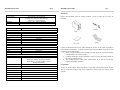
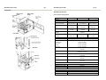
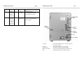
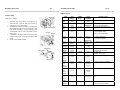
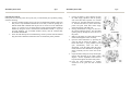
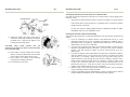
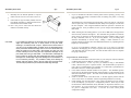
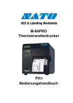
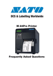
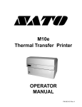
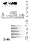
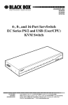
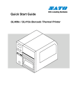
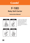
High-Performance
M-84PRO
(HQ)
(Japan)
(Singapore)
(Malaysia)
(Thailand)
(China)
(USA)
(Belgium)
(Germany)
(Poland)
(UK)
(Holland)
SATO International Pte. Ltd.
SATO Corporation
SATO Asia Pacific Pte. Ltd.
SATO Auto-ID Malaysia Sdn. Bhd.
SATO Auto-ID (Thailand) Co., Ltd
SATO Shanghai Co., Ltd
SATO America, Inc.
SATO Europe NV
SATO Deutchland GmbH
SATO Polska SP Z O.O.
SATO UK Ltd
SATO Rotterdam Logistic Center
Factory :
(Malaysia)
(Malaysia)
SATO Malaysia Electronics Manufacturing Sdn. Bhd.
SATO Labelling Malaysia Electronics Sdn.Bhd.
Quick Guide
SATO Asia Pacific Pte. Ltd.
438A Alexandra Road
#05-01/02 Alexandra Technopark
Singapore 119967
Tel : (65) 6271 5300; Fax : (65) 6273 6011
Sales Hotline : (65) 6276 2722; Service Hotline : (65) 6273 6455
Email : [email protected]
Website : www.satoworldwide.com
© Copyright 2003
SATO Asia Pacific Pte. Ltd.
Warning : This equipment complies with the requirements in Part 15 of FCC rules for a Class
A computing device. Operation of this equipment in a residential area may cause
unacceptable interference to radio and TV reception requiring the operator to take whatever
steps necessary to correct the interference.
All rights reserved. No part of this document may be reproduced or issued to third parties in
any form whatsoever without the express permission of SATO Asia Pacific Pte. Ltd. The
materials in this document are provided for general information and are subject to change
without notice. SATO Asia Pacific Pte. Ltd. assumes no responsibilities for any errors that
may appear.
SAP/M-84PRO/QG/Jan05/02
M-84PRO Quick Guide
Pg 23
Printer Overview
Accessories & Options
PCMCIA Memory Expansion
One slot for PCMCIA Memory Card (up to 4 MB SRAM or 16 MB Flash ROM). Can be
used for graphic file storage, print buffer expansion, format storage and downloaded fonts.
Flash ROM Expansion
Internal 4MB Flash ROM PCB
Real Time Clock
An internal Date/Time clock that can be used to date/time stamp labels at the time of printing.
Label Dispenser
Internally mounted attachment allowing labels to be peeled from backing for immediate (on
demand) applications. Backing not rewound.
Label Rewinder
External Option that rewinds onto a roll after they are printed.
Label Cutter
An attachment allowing labels to be cut at specified intervals.
programming.
Controlled through
Coax/Twinax Interface
Coax/Twinax Plug-In Interface module. Coax interface emulates an IBM 3287-2 printer with
a standard Type A BNC connector. Twinax interface emulates IBM 5224, 5225, 5226 or 4214
printers with auto-terminate/cable through capabilities.
Parallel Interface
IEEE1284 Bi-Directional Plug-In Interface Module.
Serial Interface
High Speed RS232 Plug-In Interface Module.
USB Interface
Universal Serial Bus Plug-In Interface Module.
Ethernet Interface
10/100 BaseT Plug-In Interface Module.
M-84PRO Quick Guide
The SATO M-84PRO Thermal Transfer Printers are complete, high-performance on-site
labelling systems. All printer parameters are user programmable using the front panel controls
and the DIP switches. All popular bar codes and 14 human-readable fonts, including a vector
font and two raster fonts, are resident in memory and thus providing a variety of available
fonts.
The Operator’s Manual will help you understand the basic operations of the printer such as
setup, installation, configuration, cleaning and maintenance.
The M-84PRO can print labels up to four inches wide and is available in three resolutions; 203
dpi, 305 dpi, 609 dpi. The resolution is determined by the print head that is installed in the
printer and can be changed in the field simply by installing the desired print head. The printer
automatically detects the resolution of the print head and loads the appropriate controlling
firmware.
The M-84PRO uses the standard SBPL. The only differences between it and other RISC
printers are the allowable values representing the print positions on the label. These values are
specified in “dots” and will vary depending on the resolution of the printer and the amount of
memory available for imaging the label. The allowable range for the various M-84PRO
models is specified in a table in the “e” and PRO Printer Programming Reference.
M-84PRO Quick Guide
Pg 1
M-84PRO Quick Guide
Pg 22
Table of Contents
Installation …………………………………………………………………….. 2
Installation ……………………………………………………………. 2
Components …………………………………………………………… 3
Media Loading ………………………………………………………………... 5
Label Stock Loading ………………………………………………….. 5
Ribbon Loading ………………………………………………………. 8
Operation Panel ………………………………………………………………... 10
Printer DIP Switch Configuration ……………………………………………. 11
RS232 Transmit/Receive Setting ……………………………………… 11
Printer Set up ………………………………………………………….. 12
Troubleshooting ………………………………………………………………..
Initial Checklist ………………………………………………………..
Using the IEEE1284 Parallel Setting ………………………………….
Using the RS232C Serial Interface ……………………………………
Using the Universal Serial Bus (USB) Interface ………………………
Using the LAN Ethernet Interface …………………………………….
Error Signals …………………………………………………………..
13
13
13
14
15
15
18
M-84PRO Specifications ………………………………………………………. 20
Accessories & Options ………………………………………………………… 22
Physical
SPECIFICATION
M-84PRO All Models
PHYSICAL
Width
10.4 in. (265 mm)
Depth
17.1 in. (435 mm)
Height
13.4 in. (341 mm)
Weight
39.7 lb. (18.0Kg)
POWER
Input Voltage
115/220 VAC +/-10%, 50/60 Hz +/-1%
Power Consumption
130 W Operating, 24W Idle
ENVIRONMENTAL
Operating
41º to 104º F (5º to 40º C)
Temperature
Storage Temperature
23º to 140º F (-5º to 60º C)
Storage Humidity
30 to 90% RH Non-Condensing
Operating Humidity
30 to 80% RH Non-Condensing
Electrostatic
8KV
Discharge
REGULATORY APPROVALS
Safety
VCCI (Class B), UL, CUL, CE, FCC (Class B)
RFI/EMI
FCC (Class B)
M-84PRO Quick Guide
Pg 21
M-84PRO Quick Guide
Pg 2
Installation
PRINT-OUTS
Vector Fonts
Rotation
Graphics
Proportional or Fixed Spacing
Font Size 50 x 50 dots to 999 x 999 dots
Helvetica, 10 Font Variations
0º , 90º , 180º , and 270º Rotation
Dot addressable, SATO Hex/Binary, BMP or PCX formats
SPECIFICATION
M-84PRO All Models
CONTROLS AND INDICATORS
Power
Green LED
On-Line
Green LED
Label
Red LED
Ribbon
Red LED
Error
Red LED
LCD Panel
2 Line x 16 Character
Label Feed
Front Panel
Power On/Off Switch
Front Panel
POTENTIOMETER ADJUSTMENTS
Print Darkness
Front Panel
Offset
Front Panel
Pitch
Font Panel
Display
Front Panel
INTERFACE CONNECTIONS
Parallel
IEEE1284 Standard
Serial
RS232C (9600 to 57600 bps) Standard
RS422/485 (9600 to 57600 bps) Optional
Ready/Busy or X-On/X-Off Flow Control
Bi-directional Status
Universal Serial Bus
USB Ver. 1.1 Standard
Ethernet
10/100 BaseT
PROCESSING
CPU
32 Bit RISC
Flash ROM
2 MB
SDRAM
16 MB
Receive Buffer
2.95 MB
Memory Expansion
See Options and Accessories
Remove the M-84PRO from the packing container. Check to make sure you have the
following:
Quick Guide
Careful consideration must be given when selecting the location of the printer, especially to
environmental considerations. To obtain optimum results from M-84PRO, always try to avoid
operation locations influenced by:
• Direct or bright sunlight, as this will make the label sensor less responsive and may
cause the label to be sensed incorrectly.
• Locations which have extreme temperature, as this can create electrical problems on
the circuits within the printer.
• The installed location of the printer should ideally be in areas free from dust,
humidity and sudden vibrations.
Consumables
Always use SATO carbon ribbons and labels or equivalent in the thermal transfer models.
The use of incorrect materials may cause malfunctions of the printer and void the printer
warranty.
M-84PRO Quick Guide
Pg 3
M-84PRO Quick Guide
Pg 20
Components
M-84PRO Specifications
General Printer Specifications
SPECIFICATION
PRINT
Method
Speed
(User Selectable)
Print Module (Dot
Size)
Resolution
Label Roll Guide
Maximum Print
Width
Maximum Print
Length
MEDIA
Minimum Width
Minimum Length
Continuous
Tear-Off
Cutter
Dispense
Maximum Width
Type
Maximum Caliper
Roll OD (max)
Face-In
Core ID (min)
SENSING
See-Thru
Reflective Eye-mark
Continuous Form
RIBBON
Maximum Width
Length (max)
Thickness
M-84PRO-2
M-84PRO-3
M-84PRO-6
Direct or Thermal Transfer
2 to 10 ips
2 to 8 ips
2 to 6 ips
50 to 250 mm/s
50 to 200 mm/s
50 to 150 mm/s
.0049 in.
.0033 in.
.0017 in.
.125 mm
.083 mm
.042 mm
203 dpi
305 dpi
609 dpi
8 d/mm
12 d/mm
24 d/mm
4.1 in.
104 mm
49.2 in.
32.8 in.
14.0 in.
1249 mm
835 mm
356 mm
.87 in. (22 mm)
0.24 in. (6 mm)
0.63 in. (16 mm)
1.18 in. (30 mm)
1.18 in. (30 mm)
5.0 in.
125 mm
Roll or Fan-Fold Die Cut Labels
Thermally Sensitive
0.008 in.
0.21 mm
8.6 in.
220 mm
3 in.
76.2 mm
Movable
Movable
Sensor Not Used
4.4 in. (111 mm)
1475 ft. (450 mm)
4.5 micron, Wound Face-In
M-84PRO Quick Guide
Error
Blinks
Ribbon
End
Download
Error R/W
Error
Mem Full
Error
CopyCard/
Format
R/W Error
No Card
Error
Mem Full
Error
Pg 19
3 Short
Ribbon End
3 Short
Download
Error
3 Short
Card Copy or
Format Error
M-84PRO Quick Guide
Pg 4
1. Needs new ribbon roll
2. Ribbon sensor needs adjustment
1. Read/Write error
2. Corrupted download file
3. Download file too large
1. R/W error during copying
2. Card not installed properly
3. File too large
AC Input
AC Fuse
Interface Slot
Memory Card Slot
EXT
Input 100-120/200-240 VAC, 50/60 Hz connector.
Use cable provided.
Input power protection. 3/1.5A rating.
Connector for Plug-In Interface Module.
Connector for optional PCMCIA Memory Card.
External signal connector, AMP 57-60140.
M-84PRO Quick Guide
Pg 5
M-84PRO Quick Guide
Pg 18
ERROR Signals
Media Loading
LED
Error
On
Error
On
Error
On
Error
On
LCD
Message
Machine
Error
EEPROM
Error
Head
Error
Sensor
Error
Audible
Beep
1 Long
Error
Blinks
Error
Blinks
Error
Blinks
Errors
Blinks
Error
Blinks
Error
On
Line
Blinks
Error
On
Line
Blinks
Error
On
Line
Blinks
Error
On
Line
Blinks
Error
Blinks
Label Stock Loading
1.
2.
3.
4.
Open the Top Access Door by swinging it up
and to the left. Open the Side Access Door by
swinging it to rear of the printer.
Open the Print Head Assembly by pushing the
Head Latch towards the rear of the printer. The
Print Head Assembly is spring-loaded and will
automatically open as soon as the Head Latch is
disengaged.
Loosen the Label Edge Guide and push it to the
outside of the printer to give the maximum label
width.
Remove the Label Roll Guide.
1 Long
Error
Condition
Machine
Error
EEPROM
Read/Write
Head
3 Short
Sensor
Card R/W
Error
1 Long
Card Low
Battery
Card No
Battery
Head
Open
Cutter
Error
Parity
Error
1 Long
3 Short
Memory
Card
Read/Write
Memory card
Battery Low
No Battery in
Card
Head Open
3 Short
Cutter
3 Short
RS232 Parity
Error
Overrun
Error
3 Short
RS232
Overrun
Error
1. RS232 parameter mismatch
Framing
Error
3 Short
RS232
Framing
Error
1. RS232 parameter
Buffer
Over
3 Short
Buffer
Overflow
1. Command stream exceeds buffer
size
Paper End
3 Short
Media End
1. No Paper
2. Paper incorrectly loaded
1 Long
1 Long
Possible Causes
1. Defective Board
1. EEPROM not installed correctly
2. Overwriting EEPROM
1. Electrical head malfunction
1. Paper jam
2. Sensor DSW setting
3. Sensor level adjustment
1. Card not formatted
2. No card recognized
1. Card battery needs adjustment
1. Card needs battery installed
1. Head not latched
2. Head latch switch bad
1. Cutter jam
2. Cutter sensor dirty
1. RS232 parameter mismatch
M-84PRO Quick Guide
Pg 17
Intermittent Problems
If the print server and the printer start up OK, but you intermittently have problems printing,
check the following:
1. Excessive NetWare polling can be a big cause of intermittent problems. Make sure
that you have only enabled the NetWare file servers that you need for printing (do a
SHOW NETWARE command from the print server console to see the enabled file
servers). If you have V3.21 or earlier firmware, make sure that NetWare polling is
disabled by using the console command SET NETWARE RANGE 0. If you are
not using NetWare, you can disable NetWare entirely with the command SET
NETWARE DISABLED.
2. Check the individual protocol troubleshooting sections provided with the Ethernet
Plug-In Interface Module for additional causes of intermittent printer problems.
M-84PRO Quick Guide
5.
If using roll labels (or tags), load the roll onto
the Label Supply Spindle so that the printing
side of the label faces upwards as it unwinds
from the roll. The labels should be wound facein. Push the roll all the way to the inside of the
printer and push Label Roll Guide snugly
against the outside of the label roll.
6. If using fanfold labels (or tags), set them on a
flat surface behind the printer. Pass the labels
(printing side up) through the slot in the rear of
the printer.
7. Make sure the labels are routed under the Label
Guide and through the Sensor Assembly.
8. Open the Label Hold-Down by squeezing the
green tab and the release tab together. The
Label Hold Down is spring loaded and will
open automatically when the latch is
disengaged. Feed the labels under the Label
Guide, under the Label Hold Down, through the
Sensor Assembly and out of the front of the
printer.
9. Inspect the label routing and verify that the path
matches that illustrated in the Label Loading
diagram. Set the Adjustable Label Guide to
keep the labels against the inside of the printer.
10. Close the Label Hold-Down by pushing
downward on the green tab until it latches
closed.
Pg 6
M-84PRO Quick Guide
Pg 7
M-84PRO Quick Guide
Pg 16
Checking the Interface between the Print Server and the Printer
First make sure that the cable between the print server and the printer is securely plugged in at
both sides. Then:
1. Wait about two minutes after the printer is powered on and then run a printer self-test.
If the self-test does not print, then there is a possibility that it is a hardware problem.
Double check the connections.
In some rare instances, disabling NBUF with the command SET PORT P1 NBUF
DISABLED will solve port compatibility issues.
11. Adjust the outside Label Edge Guide until it
touches the outside edge of the label and tighten
the thumb screw. Make sure the labels are also
touching the inside edge guides.
CAUTION: Using media narrower than the
maximum print width may cause excess head wear
due to the label edge.
12. If the ribbon is already loaded, close the Print
Head by rotating the black Head Latch towards
the front of the printer until it latches closed.
13. If the ribbon is not loaded, see the following
descriptions for loading instructions.
14. Close both the Access Doors.
Checking the Network Connection and Cabling
If the self-test page prints but you cannot print documents, first check network connection and
cabling.
1. If you are connecting to a 10baseT network, verify that the OK LED is on. If the
appropriate LEDS are not on, there is probably a bad 10BaseT or 100BaseT cable or
the hub port is bad. If possible, try a different cable and hub port, or try connecting a
different device (such as a PC) to the cable.
2. If you are using a repeater or hub, make sure that SQE (heartbeat) is turned off at the
hub (that is the default setting for most hubs). Also, if you have a hub or multiport
repeater, verify that the hub or repeater is good by trying the print server on a
different port.
3. If you have a bridge or router located between the print server and the host computer,
make sure that the device is set up to allow the print server to send and receive data
from the host. For example, a bridge can be set up to only allow certain types of
Ethernet addresses to pass through (a process known as filtering); therefore, such a
bridge must be configured to allow print server addresses. Likewise a router can be
set up to pass only certain protocols, so be sure that the desired protocol can be
passed to the print server. In the case of routers, also make sure that the protocol is
routable (LAT, NetBEUI and DLC/LLC are not routable).
4. Make sure that you are not trying to perform an illegal operation, such as attempting
to print a label larger than the printer can handle.
5. Check the individual protocol troubleshooting sections provided with the Ethernet
Interface Module for additional causes of intermittent printer problems.
M-84PRO Quick Guide
6.
7.
Pg 15
If you are still unable to get printer output, try the Hex Dump as described in Step 5
under the Parallel Interface troubleshooting. In this case, the printer monitors the
RS232C interface for incoming data.
From the Hex Dump, if you are seeing extra 0DH 0AH (CR and LF) characters, and
are using BASIC, refer to PRO Printer Programming Reference. It provides hints for
writing a SATO program in BASIC.
M-84PRO Quick Guide
Pg 8
Ribbon Loading
Using the Universal Serial Bus (USB) Interface
If nothing prints when doing a test print you will need to verify that the device drivers have
been successfully installed by doing the following:
1.
2.
3.
4.
5.
6.
7.
Click on Start, then Settings and then Control Panel.
Within the new Window you should have an Icon listed as System. Double Click on
this.
Click on the Device Manager tab.
Make sure that the View Device by type is checked. Scroll down until you get to
SATO-USB device.
Verify that it does not have any errors next to it. If it shows an error, remove the
device and then reinstall it.
Reboot the PC and the Printer.
Consult the Windows Troubleshooting guide or contact technical support for further
assistance.
1.
2.
3.
Using the LAN Ethernet Interface
4.
Printer Does Not Come Up Ready
If you cannot print to the print server after you install it, check the following:
5.
1.
2.
Make sure that the printer is powered on, that all cables are securely plugged in, and
that the printer is on-line.
If possible, connect a terminal to the serial port. If you see the boot prompt, the print
server firmware has not been loaded properly. If reloading does not fix the problem,
try setting switch 1 to ON (factory defaults) and powering the print server off and
then on again; if the problem persists, the product may be defective.
Installation Problems (Printer Comes Up Ready But You Cannot Print)
If the printer starts up OK but you cannot print, the problem could be one of the following:
1.
2.
3.
There is a problem with the interface between the print server and the printer.
There is a problem with the network connection or cabling.
There is a queue setup problem, a print server setup problem, or other protocolrelated problem.
6.
Open the Access Door by swinging it up and to the
left and the Side Access Door by swinging it toward
the rear of the printer.
Open the Print Head by rotating the Head Latch
towards the rear of the printer. The Print Head is
spring-loaded and will automatically open as soon as
the Head Latch is disengaged.
Locate the extra ribbon core supplied with the printer.
Place the core on the Ribbon Rewind Spindle,
pushing it all the way to the inside of the spindle. Note that the new empty core of
each subsequent roll becomes the next rewind core.
Load the ribbon onto the Ribbon Supply Spindle, also pushing it all the way to the
inside of the spindle. The dull side of the ribbon should be facing down as it travels
through the Print Head Assembly.
Feed the leader portion of the ribbon through the Print Head Assembly and up to the
Ribbon Rewind Spindle following the routing shown in the diagram.
Load the ribbon behind and over the top of the Ribbon Rewind Spindle and tape it to
the Extra Ribbon Core. Make sure it matches the ribbon path shown in the diagram.
M-84PRO Quick Guide
7.
Pg 9
Manually turn the Rewind Spindle to wrap the
ribbon onto the core one to two turns to secure it.
M-84PRO Quick Guide
7.
8.
9.
If the labels or tags are already loaded, close the
Print Head Assembly by pushing downwards on
the black tab until it latches closed.
10. Run a test print to ensure that the labels and
ribbons were loaded correctly.
If your labels are less than the full width of the print head, the outside
edge will eventually wear out a small portion of the print head,
resulting in an area that will not print. Special care must be taken if
you plan to use multiple widths of labels, since the damaged portion
of the print head caused from edge wear on a more narrow label may
affect the printing on a wider label. We suggest you plan your print
formats carefully to avoid using the area of possible damage on the
print head when using a wider label. The small area of damage will
have no effect on printing with the undamaged part of the print head.
Damage from a label edge is physical damage and is unavoidable. It
is not covered by warranty. It is possible to delay such damage by
always ensuring that the ribbon used is wider than the label stock.
This will help to protect the print head from label edge damage.
If you’ve checked all of the above and the printer still isn’t printing, you may want
to try a Buffer Hex Dump to determine what (if anything) the printer is receiving
from your computer.
The Parallel port is now listening for incoming data. Send your print job. The printer
will now print (only once) a Hexadecimal (Hex) Dump of everything it received from
the host computer. Each 2-digit hexadecimal character represents a character the
printer received. It may be tedious, but now you can analyze and troubleshoot the
data stream.
8.
CAUTION:
Pg 14
While checking the Hex Dump printout, if you notice 0DH 0AH (Carriage Return
and Line Feed) characters throughout. The command string should be continuous
and no CR or LF characters are allowed between the Start Command (<ESC>A) and
the Stop Command (<ESC>Z). If you are using BASIC, it may be adding these
characters automatically as the line wraps. Adding a “width” statement to your
program and help to suppress these extra 0DH 0AH characters by expanding the line
length up to 225 characters.
If you’re not programming in BASIC, check to see if you have an equivalent
statement in the language you’re using to suppress extra carriage and line feeds from
your data being sent out to the printer. We want the data stream to be one complete
line going to the printer.
Using the RS232C Serial Interface
1. Is the RS232C Serial cable connected securely to your serial port on the PC (DB-25S
or DB-9S Male) and to the RS232C connector on the printer?
2. Is the cable defective? At the very least, you should be using a “Null Modem
Cable”, which crosses pins in a specific manner. This should enable your printer to
print. But we recommend that you eventually use a cable built to specifications as
described in Section 6: Interface Specifications.
3. Is the RS232 Interface Module installed in the printer? The M-84PRO printers
require the new Hi Speed Serial Interface (PN WCL40451) to take advantage of the
faster data transmission speeds. The older Serial Interface Modules will work, but
at a reduced capability.
4. Check for obvious errors in the data stream. Is the data properly framed with the
<ESC>A and <ESC>Z commands? See the Programming Reference if necessary.
5. If after sending your job to the printer, it only “beeps” and displays an error message
on the LCD display, you may have a configuration problem. There may be some
inconsistencies with the Baud Rate, Parity, Data Bits, or Stop Bits in relation to your
host computer. If you are confused as to what the printer’s current RS232 settings
are, print a Configuration Test label. It will list all of the current printer
configuration settings.
M-84PRO Quick Guide
Pg 13
Troubleshooting
M-84PRO Quick Guide
Pg 10
Operation Panel
Initial Checklist
1.
Is the printer powered up and ON-LINE?
2.
Is the ERROR light on the front panel off? If this light is on, it may mean the
Print Head Assembly or the Label Hold-Down is not closed and latched in
position.
3.
Are the LABEL and RIBBON lights on the front panel off? If these lights are on,
the labels or ribbons may be incorrectly loaded.
Using the IEEE1284 Parallel Interface
1. Is the IEEE1284 printer cable connected securely to your parallel port (DB-25S
Female) on the PC and to the Parallel Interface connector on the printer?
2. Does the Parallel interface cable used meet IEEE1284 specifications? If it does not
and you are connected to an IEEE1284 or ECP parallel port on the computer, the
printer may not be able to communicate correctly.
3. Is there more than one parallel interface port on your PC (LPT1, LPT2, etc)? If so,
make sure you are sending data out the correct port.
4. Is the IEEE1284 Interface Module installed in the printer? Older versions of the
Parallel Interface module will not work correctly in the M-84PRO printers.
5. When you send the print job to the printer, and it does not respond, do you get an
error message on your PC that says “Device Fault” or something similar?
6.
This may mean that the computer doesn’t know the printer is there. Verify that:
a. Both ends of the cable are securely inserted into their respective connectors.
b. The printer is ONLINE.
c. The cable is not defective. There are other things that can cause this error
message on your computer, but at this stage, a defective cable may be one of
the reasons.
When you send the print job to the printer and it does not respond, and there is no
error message on the PC:
a.
b.
c.
Check your data stream for some of the basics. Is your job framed as
follows?
<ESC>A – DATA – <ESC>Z
Verify that you’ve included all required parameters in the data stream.
Verify the following:
You have not typed a “0” (zero) for an “O” (letter) or vice versa.
You have not missed any <ESC> characters where they’re needed.
Make sure all printer command codes are capital letters.
The M-84PRO Operator Panel consists of five LED indicators, two momentary contact
switches, three DIP switches, four adjustment potentiometers and one LCD Display. All of
these are accessible from the front of the printer. They are used to set the printer operating
parameters and to indicate the status of the printer to the operator. After you power on the
printer, familiarize yourself with the keys and indicators as it will help you understand the
configuration process.
PRINT
OFFSET
PITCH
DISPLAY
POWER
LABEL
RIBBON
ERROR
ON LINE
LINE
Potentiometer to adjust print darkness (fine tuning).
Potentiometer to adjust amount of back/forward feed for
dispenser/cutter/tear-off position (+/- 3.75 mm).
Potentiometer to adjust home position of the label (+/- 3.75 mm). Affects
stop position of label feed, print position and dispense position.
Potentiometer to adjust the contrast of the LCD display.
LED, illuminated when power is on.
LED, illuminated when the label supply is not detected.
LED, illuminated when the ribbon motion sensor does not detect any ribbon
motion (ribbon out condition).
LED, illuminated when there is a system fault such as an open print head.
LED, illuminated when printer is ready to receive data. Toggled on/off with
LINE key.
Momentary switch. Pressing this key toggles the printer between the on-line
and off-line mode. When the printer is on-line, it is ready to receive data
from the host. This key acts as a pause during a print job by taking the
printer off-line. It can also be used as a Pause function key to stop the
printer during the printing process.
M-84PRO Quick Guide
FEED
DSW
LCD
Pg 11
Momentary switch. Pressing this key feeds one blank label when the printer
is off-line. When the printer is on-line, another copy of the last label will be
printed (Reprint W/Feed must be enabled in the LCD panel Service Mode).
DIP switch array to set operational parameters of the printer.
2 Line x 16 Character LCD display. Used for setting operational parameters
of the printer and displaying error conditions.
M-84PRO Quick Guide
Pg 12
Printer Set Up
Print Mode Selection (DSW2-1) – Selects between direct thermal printing on thermally
sensitive paper and thermal transfer printing using a ribbon.
Sensor Type Selection (DSW2-2) – Selects between the use of a label gap or a reflective EyeMark detector.
Head Check Selection (DSW2-3) – When selected, the printer will check for heads elements
that are electrically malfunctioning.
Printer DIP Switch Configuration
There are two DIP switches (DSW2 and DSW3) located on the front panel under a protective
cover. In addition, a third DIP switch is located on the RS232C Serial Adapter card and is
used to set the RS232C transmit/receive parameters. These switches can be used to set:
• Thermal transfer or direct thermal mode
• Label sensor enable/disable
• Head check mode
• Hex dump mode
• Single Job or Multi-Job Receive buffer
• Operation mode
Each switch is an eight section toggle switch. The ON position is always up. To set the
switches, first power the unit OFF, then position the DIP switches. Finally, after placing the
switches in the desired positions, power the printer back on. The switch settings are read by
the printer electronics during the power up sequence. They will not become effective until the
power is cycled.
RS232 Transmit/Receive Setting
Data Bit Selection (DSW1-1) – This switch sets the printer to receive either 7 or 8 data bits
for each byte transmitted.
Parity Selection (DSW1-2, DSW1-3) – These switches select the type of parity used for error
detection.
Stop Bit Selection (DSW1-4) – Selects the number of stop bits to end each byte transmission.
Baud Rate Selection (DSW1-5, DSW1-6) – Selects the data rate (bps) for the RS232 port.
Protocol Selection (DSW1-7, DSW1-8) – Selects the flow control and status reporting
protocols.
Hex Dump Selection (DSW2-4) – Selects Hex Dump mode.
Receive Buffer Selection (DSW2-5) – Selects the operating mode of the receive buffer.
Firmware Download (DSW2-6) – Places the printer in the Firmware Download mode for
downloading new firmware into flash ROM.
Protocol Code Selection (DSW2-7) – Selects the command used for protocol control.
Status Select (DSW2-8) – For emulating earlier series software commands. Should be used
only if problems are encountered using existing software. This switch will also affect the
settings selected by DSW1-7 and DSW1-8.
Backfeed Sequence (DSW3-1, DSW3-2) – Backfeed is used to correctly position the label for
application and then retract the next label to the proper print position. This operation can be
performed immediately after a label is printed and used, or immediately prior to the printing of
the next label.
Label Sensor Selection (DSW3-3) – Enables or disables the Label Sensor. If the Sensor is
enabled, it will detect the edge of the label and position it automatically. If it is disabled, the
positioning must be under software control using Line Feed commands.
Back-Feed Selection (DSW3-4) – When Back-Feed is enabled, the printer will position the
last printed label for dispensing and retract it before printing the next label. The amount of
backfeed offset is adjustable.
EXT Print Start Signal Selection (DSW3-5) – Allows an external device to initiate a label
print for synchronization with the applicator. When DSW3-5 is On, the unit is in the
Continuous print mode, Backfeed is disabled and External Signals are ignored.
External Signal Type Selection (DSW3-6, DSW3-7) – Both the polarity and signal type
(level or pulse) of the external print synchronizing signal can be selected.
External Print via External Signal (DSW3-8) – Allows the applicator to reprint the current
label in the print buffer.