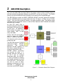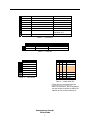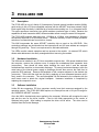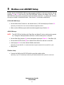
1
ARC-EVS
ARCNET Evaluation System
User Manual
# TD020200-0MA
Trademarks
Contemporary Controls and ARC Control are registered trademarks of Contemporary Control
Systems, Inc. ARCNET is a registered trademark of Datapoint Corporation. Other product
names may be trademarks or registered trademarks of their respective companies.
Copyright
© Copyright 2002, by Contemporary Control Systems, Inc. All rights reserved. No part of this
publication may be reproduced, transmitted, transcribed, stored in a retrieval system, or
translated into any language or computer language, in any form or by any means, electronic,
mechanical, magnetic, optical, chemical, manual, or otherwise, without the prior written
permission of:
Contemporary Control Systems, Inc.
2431 Curtiss Street
Downers Grove, Illinois 60515 USA
Tel:
Fax:
E-mail:
WWW:
+1-630-963-7070
+1-630-963-0109
[email protected]
http://www.ccontrols.com
Contemporary Controls Ltd
Barclays Venture Centre
University of Warwick Science Park
Sir William Lyons Road
Coventry CV4 7EZ UK
Tel:
Fax:
E-mail:
WWW:
+44 (0)24 7641 3786
+44 (0)24 7641 3923
[email protected]
http://www.ccontrols.eu
Tel:
Fax:
E-mail:
WWW:
+86-21-62551335
+86-21-62552925
[email protected]
http://www.ccontrols.com.cn
Contemporary Controls Shanghai
Representative Office
Room 1012, Zhongchuang Building
819 Nanjing Road (W.)
Shanghai 200041, China
Disclaimer
Contemporary Control Systems, Inc. reserves the right to make changes in the specifications of
the product described within this manual at any time without notice and without obligation of
Contemporary Control Systems, Inc. to notify any person of such revision or change.
Warning — This is a Class A product as defined in EN55022.
In a domestic environment this product may cause radio interference
in which case the user may be required to take adequate measures.
Contemporary Controls
TD020200-0MA
i
Table of Contents
1
Introduction ......................................................................................................... 1
1.1
Description...................................................................................................................................................1
1.2
Kit Features..................................................................................................................................................2
1.3
ARCNET Evaluation Board Specifications ..................................................................................................3
1.4
PCI22-485X Specifications ..........................................................................................................................4
1.5
Fieldbus Connectors ....................................................................................................................................5
2
ARC-EVB Description ......................................................................................... 6
3
PCI22-485X NIM .................................................................................................. 8
3.1
Description...................................................................................................................................................8
3.2
Hardware Installation..................................................................................................................................8
3.3
Software Installation ....................................................................................................................................8
3.4
Indicator Lights............................................................................................................................................9
3.5
Node ID Switch ............................................................................................................................................9
3.6
Fieldbus Connection ....................................................................................................................................9
4
Source Code ...................................................................................................... 10
5
Modbus-over-ARCNET Setup........................................................................... 11
6
Modbus-over-ARCNET Operation .................................................................... 14
7
Firmware Modification ...................................................................................... 15
8
Keil Compiler/Debugger.................................................................................... 18
9
Service................................................................................................................ 20
9.1
Warranty ....................................................................................................................................................20
9.2
Technical Support ......................................................................................................................................20
9.3
Warranty Repair ........................................................................................................................................21
9.4
Non-Warranty Repair.................................................................................................................................21
9.5
Returning Products for Repair...................................................................................................................21
10
Appendix ............................................................................................................ 22
10.1
Modbus Message Format...........................................................................................................................22
10.2
ARC-EVB Component Layout ....................................................................................................................23
10.3
ARC-EVB Schematic Diagram...................................................................................................................24
Contemporary Controls
TD020200-0MA
ii
Figures
Figure 1 — ARC-EVS Components ........................................................................... 1
Figure 2 — Evaluation Board Block Diagram........................................................... 6
Figure 3 — PCI22-485X Indicator Lights and Node ID Switch................................. 9
Figure 4 — ARC-EVB Control Panel — Inactive..................................................... 12
Figure 5 — Application Settings.............................................................................. 12
Figure 6 — ARC-EVB Control Panel — Active ....................................................... 13
Figure 7 — LED Status ............................................................................................. 14
Figure 8 — LED Control ........................................................................................... 14
Figure 9 — Atmel Flip Initial Screen........................................................................ 15
Figure 10 — Device-Specific Panel before Reading the T89C51RB2 ..................... 16
Figure 11 — RS232 Options....................................................................................... 16
Figure 12 — Device-Specific Panel after Reading the T89C51RB2 ........................ 17
Figure 13 — Evaluation Board Layout ...................................................................... 23
Tables
Table 1 — Connectors .................................................................................................. 7
Table 2 — Switches....................................................................................................... 7
Table 3 — Test Points ................................................................................................... 7
Table 4 — Data Rate (J8) .............................................................................................. 7
Contemporary Controls
TD020200-0MA
iii
1
Introduction
1.1
Description
The ARCNET Evaluation System (ARC-EVS) is a very useful tool for exploring embedded
ARCNET. The system contains:
•
one ARCNET Evaluation Board (ARC-EVB)
•
one PCI22-485X ARCNET network interface module (NIM)
•
one wall-mount power supply
•
one null-modem cable
•
one modular cable
•
one RJ-11 modular cable terminator
•
one RJ-45 modular cable terminator
•
one CD-ROM
Figure 1 —ARC-EVS Components
The ARC-EVB contains a microcontroller that allows users to upload their firmware into FLASH
and execute it. It also works with the Keil compiler, which allows users to debug their ARCNET
code on the board. The CPU is provided with external RAM to allow users to load up to 30 KB
of firmware. The PCI22-485X is a PCI-based COM20022 ARCNET card. When the card is
installed in a computer and connected to the ARC-EVB via the provided modular cable, a
complete ARCNET network is created.
Contemporary Controls
TD000800-0MA
1
1.2
Kit Features
•
ARCNET compliant (ANSI/ATA 878.1)
•
Industrial temperature range (–40ºC to +85ºC)
•
Employs standard TTL signal levels
•
Dual RJ-11 jacks for EIA-485X ARCNET
•
Dual D-Sub 9 plugs for serial communication
•
Prototyping area with dual resettable fuses for Vcc
•
Linear power supply
•
One 8-pole DIP switch for Node ID
•
One 8-pole DIP switch for data input
•
8 LEDs for input indication
•
8 LEDs for output indication
•
LED for power indication
Contemporary Controls
TD020200-0MA
2
1.3
ARCNET Evaluation Board Specifications
Electrical
Power Requirements:
Power Consumption:
1.8 W, maximum (with all LEDs lit)
Voltage:
9–24 VDC
Current:
commensurate with applied voltage
Environmental
Operating Temperature:
Storage Temperature:
0ºC to+60ºC
–40ºC to+85ºC
Data Rates
10 Mbps, 5 Mbps, 2.5 Mbps, 1.25 Mbps
Dimensions
7" x 4" (178 mm x 102 mm)
Functional
Digital Signals:
Number
Type
Input or Output:
8
TTL, 5 V
Input Signal Voltage:
0–5 V
Maximum Output Low:
450 mV, 1.6 mA
Minimum Output High:
4.5 V, 10 µA
Serial Port:
TTL, 5 V
ARCNET Compliance
ANSI/ATA 878.1
LED Indicators
Function
Number
Color
Power
1
Green
CPU Access
1
Yellow
Fieldbus Data Received
1
Green
Input Signals
8
Red
Output Signals
8
Red
Contemporary Controls
TD020200-0MA
3
1.4
PCI22-485X Specifications
Environmental
Operating Temperature:
Storage Temperature:
0ºC to+60ºC
–40ºC to+85ºC
Data Rates
10 Mbps, 5 Mbps, 2.5 Mbps, 1.25 Mbps
Dimensions
4.20" x 5.5" (107 mm x 140 mm)
I/O Mapping
Requires 16 bytes of I/O space for COM20022 controller
Interrupt Lines
Supports PCI INTA
Compatibility
Fully compatible with all of Contemporary Controls ARCNET products and PCI bus
computers.
Regulatory Compliance
CE Mark
FCC Part 15 Class A
Power Requirements
Voltage:
+5V
Current:
400mA
LED Indicators
Function
Number
Color
Host CPU Access
1
Yellow
Fieldbus Data Transmitted
1
Green
Contemporary Controls
TD020200-0MA
4
1.5
Fieldbus Connectors
Two cabling methods are provided for the fieldbus and differ by their connector type.
Identical open-wire, 3-terminal connectors are available on both the ARC-EVB and the NIM:
Open-Wire Connector
Pin Assignments
Pin
Usage
1
Signal
2
Signal
3
Shield
The ARC-EVB modular connector is of the RJ-11 type:
RJ-11 Modular Connector
Pin Assignments
Pin
Usage
1
Not Installed
2
Not Used
3
Signal
4
Signal
5
Not Used
6
Not Installed
The NIM modular connector is of the RJ-45 type:
RJ-45 Modular Connector
Pin Assignments
Pin
Usage
1
Not Used
2
Not Used
3
Not Used
4
Signal
5
Signal
6
Not Used
7
Not Used
8
Not Used
Contemporary Controls
TD020200-0MA
5
2
ARC-EVB Description
The core of the ARC-EVB is an Atmel T89C51 CPU which contains 16 KB of FLASH memory to
hold the provided test application (Modbus-over-ARCNET)—or the user’s firmware. The FLASH
memory can also hold the Keil monitor, allowing it to work with the Keil compiler/debugger.
The ARC-EVB also contains an SMSC COM20022 ARCNET controller (backward compatible
with the COM20020) which can support data rates from 156 kbps to 10 Mbps using a 20 MHz
crystal. This chip offers enhanced features over earlier generation chips. New features include
command chaining, sequential access to internal RAM, duplicate Node ID detection and variable
data rates up to 10 Mbps.
An 8-bit DIP switch (S1) is
provided as the input device and 8
associated LEDs report the state
of each input. An additional 8
LEDs indicate the states of the
output signals. LED 7 in each
array is the MSB.
Another 8-bit DIP switch (S2) is
used for setting the ARCNET
Node ID. Switch 8 is the MSB.
The data rate is set by jumpers at
jumper block J8.
The ARC-EVB uses an HYC4000
transformer-coupled
ARCNET
transceiver.
This
provides
balanced EIA-485 signaling so
that either a straight-through or a
crossover cable can be used.
ARCNET fieldbus connections
are provided by either a 3terminal open-wire connector or
an RJ-11 jack for standard
twisted-pair cable. An extra RJ11 jack is provided for installing
the modular terminator provided
in the ARC-EVS. The extra jack
can also be used for daisychaining a twisted-pair bus if the
ARC-EVB is configured with
more than one ARCNET adapter.
Figure 2 — Evaluation Board Block Diagram
Contemporary Controls
TD020200-0MA
6
J1 2-pin header
Boot ROM (for FLASH reprogramming)
Leave off in normal operation
J2 D-SUB 9
CPU UART
Firmware upload and debug
J3 D-SUB 9
Extra serial port
Customer SPI development
J4 RJ-11
ARCNET RJ-11 port
Connect to PCI22-485X
J5 RJ-11
ARCNET RJ-11 port
Connect terminator here
J6 Open 3-wire
ARCNET 3 wire port
Extra ARCNET port
J7 30-pin header
Prototyping header
J8 6-pin header
ARCNET data rate
Set to desired rate (Table 4
—
Data Rate (J8))
J9
Power input connector
Using provided power supply
Table 1 — Connectors
Type
Usage
Comment
S1 8-pin DIP
Data Input
Set to desired data value
S2 8-pin DIP
ARCNET Node ID
Set to ARC-EVB ARCNET node ID
Table 2 — Switches
Usage
DR0 DR1 DR2
Data Rate
TP1
VCC
—
—
—
2.5
Mbps
TP2
GND
X
—
—
1.25
Mbps
TP3
Pulse1 ARCNET signal
—
X
—
625 *
kbps
TP4
RXIN received ARCNET
X
X
—
312.5 *
kbps
TP5
TXEN transmit enable
—
—
X
156.25 * kbps
TP6
EIA-485 output (Φ B)
X
—
X
5
Mbps
TP7
EIA-485 output (Φ A)
—
X
X
10
Mbps
X
X
X
Table 3 — Test Points
N/A
( X = jumper installed )
Table 4 — Data Rate (J8)
* These rates are not supported by the
ARC-EVB transceiver, but are available if
the user wishes to replace the ARC-EVB
transceiver with a custom transceiver.
Contemporary Controls
TD020200-0MA
7
3
PCI22-485X NIM
3.1
Description
The PCI22-485X is one of a family of Contemporary Controls network interface modules (NIMs),
each serving to link a PCI bus compatible computer with the ARCNET local area network (LAN).
Each model within the family is identified by a model number ending in a 3- or 4-character suffix.
This suffix specifies a transceiver type which matches a particular type of cable. Because the
capabilities of each transceiver differ, different models cannot occupy the same LAN segment.
The PCI22-485X supports data rates from 1.25 Mbps to 10 Mbps and operates in a Windows
environment with one of our null stack drivers. The driver directory on the CD-ROM provides a
selection of null stack drivers from which to choose.
This NIM incorporates the same ARCNET controller chip as used on the ARC-EVB. Bus
contention problems are minimized since the interrupt level and I/O base address are assigned
through Plug and Play. There is no requirement for wait-state arbitration.
Two LEDs monitor network operation and bus access to the module. An external DIP switch
allows node addresses to be easily reassigned without removing the module.
3.2
Hardware Installation
The NIM can be installed in any PCI bus compatible computer bus. With power detached from
the computer, remove the computer cover to expose the motherboard and expansion slots
(connectors). Care should be taken when installing the card; both it and the exposed
motherboard are sensitive to electrostatic discharge. To prevent inadvertent damage, touch the
metal case of the internal power supply to discharge yourself then remove the card from its
protective ESD package. Remove the backplate of the computer adjacent to the desired slot
(connector). Then insert the card into this slot by applying an even downward pressure until it
firmly seats in the connector. The card’s backplate can be fastened to the computer with the
small screw used to attach the original backplate. Hardware installation is completed by
replacing the computer’s cover.
3.3
Software Installation
Unlike ISA bus computers, PCI bus computers usually have their resources assigned by the
operating system. The PCI22-485X NIM requires one interrupt line and a 16 byte I/O range for
the COM20022 ARCNET controller.
Once the NIM is inserted and power applied to the computer, Windows will recognize the card
and ask the user for the driver location. Point to the folder appropriate to the version of
Windows being used. After loading is complete the driver will be active. The driver can be
disabled from the Device Manager.
Contemporary Controls
TD020200-0MA
8
3.4
Indicator Lights
There are two LEDs located at the NIM’s backplate. The green LED indicates that the card is
transmitting ARCNET traffic to the network. The yellow LED indicates that the card is being
accessed from the host computer via its I/O address.
Figure 3 — PCI22-485X Indicator Lights and Node ID Switch
3.5
Node ID Switch
Although not always needed, this NIM has a separate input port that reads an 8-bit DIP switch
(SW1) located at the backplate. This switch is meant to serve as a Node ID switch, although it
can serve as a general purpose switch if desired. The switch has no connection to the
COM20022 controller chip.
The most significant bit (MSB) is switch position 8, and the least significant bit (LSB) is switch
position 1. A switch in the open position (off position or away from the printed circuit board)
introduces a logic “1.” In the example below, the switch is set to hexadecimal address AF.
3.6
Fieldbus Connection
The PCI22-485X NIM supports AC-coupled communication via its daughter board which has a
fixed-bias network isolated by a pulse transformer. Unlike DC-coupled devices, bias adjustment
is unneeded and wiring polarity is unimportant. Dual RJ-45 jacks and one three-position screw
terminal connector are the options for attaching the field bus wiring. For convenience, a
modular cable is provided for connecting the NIM to the ARC-EVB.
Each end of the fieldbus wiring must have a proper value of termination resistance. The NIM
provides two options to achieve proper termination:
Onboard Termination: Install the E1 jumper on the daughter board to apply an onboard
resistance across the twisted-pair. If the jumper is removed, no termination is applied.
External Termination: If you wish to enable or disable termination without removing the NIM
from the host computer, external termination can be used. In this case, remove jumper E1 and
insert either the provided RJ-45 modular terminator in the unused RJ-45 jack or a 120 ohm 1/4
watt resistor across pins 1 and 2 on the screw terminal connector.
NOTE: Terminating with a value less than 100 ohms will excessively load the EIA-485
transceivers—so you must only use one method of termination at a time. If more ARCNET
devices are attached to the NIM and the ARC-EVB in a bus topology, only apply termination to
the devices located at the ends of the bus.
Contemporary Controls
TD020200-0MA
9
4
Source Code
The ARC-EVB is provided with Modbus-over-ARCNET example code for both server and client.
When the server example code is executed on the ARC-EVB, it can receive one byte of output
data and can transmit one byte of input data when polled by the Modbus client. The 8 LEDs on
the ARC-EVB are used to indicate the received output data. The 8-bit DIP switch (S1) is used
to provide ARC-EVB input data.
The client software executes on a PC in which our PCI22-485X has been installed and requires
the version of our Null Stack driver appropriate to the version of Windows being used. The
Modbus client will continually request current Modbus data from the Modbus server (ARC-EVB)
and will also update server output data when modified by the user.
The ARCNET Control Panel is illustrated in Figure 4. The server application causes the current
ARC-EVB input data to be displayed in the LED Status section of the panel and can change the
ARC-EVB output data in the LED control section of the panel. The 8 output LEDs on the ARCEVB are used to display its output state.
Also included is a Keil monitor HEX file that (when copied to the ARC-EVB) allows the ARCEVB to communicate with the Keil debugger. The HEX file for the Modbus-over-ARCNET
server is also provided. This allows the user to switch between debugging with the Keil
compiler and executing the Modbus-over-ARCNET server.
Updated versions of Modbus-over-ARCNET client and server can be downloaded from
www.ccontrols.com.
Contemporary Controls
TD020200-0MA
10
5
Modbus-over-ARCNET Setup
Confirm that the PCI22-485X NIM has been properly installed in the host computer (as per
Sections 3.2 and 3.3) and that the ARC-EVB EEPROM contains the Modbus hex file. The
ARC-EVB has been factory programmed with the Modbus firmware—so loading this firmware
will only be needed if it has been erased. (See Section 7 for firmware modification).
PCI22-485X NIM Setup:
• Set the NIM’s Node ID switch to the desired value (1–255, decimal) as per Section 3.5.
Optionally, the Node ID can be set via the Windows Application below.
• Make sure the NIM has proper cable termination applied as per Section 3.6.
ARC-EVB Setup:
NOTE: The ARC-EVB will initialize with Data Rate and Node ID values existing during power
up. Changes to these parameters will have no effect unless power is recycled.
• Set the Data Rate jumpers (J8) to the desired data rate as per Table 4 — Data Rate (J8).
• Set the Node ID DIP switch (S2) to a Node ID that differs from that set on the NIM.
• Install jumper JP1 to invoke onboard fieldbus termination.
Optionally, the provided RJ-11 modular terminator may be inserted in the unused RJ-11 jack.
• Apply power.
Fieldbus Setup:
• Connect the NIM to the ARC-EVB with the provided modular cable.
Optionally, any CAT-5 twisted-pair cable may be attached between the open-wire connectors.
Contemporary Controls
TD020200-0MA
11
Windows Application Setup:
•
Launching the application will display the Control Panel in Figure 4. Until the Settings
Panel options have been entered, the Control Panel features will remain inactive.
Figure 4 — ARC-EVB Control Panel — Inactive
•
Selecting the Settings menu item will display the Settings Panel in Figure 5.
Figure 5 — Application Settings
•
In the Node ID box enter the ARCNET Node ID to be associated with the NIM (and its
host computer). A zero value causes the Node ID to be read from the NIM’s DIP switch.
•
The Board Number field specifies how many ARCNET NIMS are installed in the host
computer. The default value of “1” rarely needs changing. If more Contemporary
Controls PCI-based NIMS are installed, enter that number.
•
In the Data Rate box select the data rate which matches that set on the ARC-EVB.
Contemporary Controls
TD020200-0MA
12
After completing the settings, the Control Panel will appear as in Figure 6. Three fields are
“dimmed” because they are read-only — Read Status, Control Status and Number of Recons.
Figure 6 — ARC-EVB Control Panel — Active
•
Enter a hex value for the Destination Node ID which agrees with the DIP switch value set on
the ARC-EVB. This value must differ from the ID value set for the NIM.
•
The application is now ready for operation.
Contemporary Controls
TD020200-0MA
13
6
Modbus-over-ARCNET Operation
When the ARC-EVB and the Windows application have achieved proper communications, the
Control Panel will affect operation as follows.
Reading LED Status from the ARC-EVB
Clicking the Start Button, will initiate the transmission of
Modbus Function 3H Query Messages (see Section 10.1).
The application will continually read information from the
Input DIP switch (S1) on the ARC-EVB. Each time the
read action is successful, the message “RX OK!” will
appear in the Read Status field. As long as the ARCEVB is working, each change to the Input DIP switch will
instantly appear in the LED Status area of the Control
Panel. Turning a switch “On” lights its associated LED
on the ARC-EVB and causes its associated LED icon in
the Control Panel to glow red. In the example shown in
Figure 7, switches 4-7 have been turned on.
Figure 7 — LED Status
While the Start Button is dim, changing the value in the
Destination ID field will have no effect on the read action. Clicking the Stop Button concludes
the read action, but the last data read continues to display. The next time the Start Button is
clicked, the read function will use the current value in the Destination ID field — but the read
action will not be successful unless this new value matches the Node ID value with which the
ARC-EVB was initialized.
Controlling LEDs on the ARC-EVB
Changes in LED Control will affect the
Output LEDs on the ARC-EVB. LED
Control has 8 checkboxes. Each time
a checkbox is clicked, two things are
determined — the Destination ID and
the status of all 8 checkboxes. The
checkbox data are transmitted via a
Modbus Function 10H Query Message
(see Section 10.1) to activate the
corresponding LEDs on the ARC-EVB.
But the transmission will fail unless the
Destination ID matches the Node ID
with which the ARC-EVB was initialized.
Figure 8 — LED Control
Figure 8 shows a query to activate
LEDs 0 and 2 has been successfully sent to Node ID 1. The Control Status message “RX OK!”
only means that a properly formatted query and response were exchanged. It does not confirm
that the correct data arrived at the destination.
Number of Recons
Network reconfigurations are counted in this field. The count can be reset to zero only by
restarting the application.
Contemporary Controls
TD020200-0MA
14
7
Firmware Modification
The Atmel Flip application included on the CD-ROM is used to modify the ARC-EVB firmware.
The application includes detailed online help, but a procedural overview is presented below.
Procedure:
1. Connect the ARC-EVB to a PC via the provided null-modem cable.
2. On the ARC-EVB, install the J1 jumper to enable firmware modification.
3. Apply power to the ARC-EVB.
4. Launch the Atmel Flip application.
Figure 9 — Atmel Flip Initial Screen
5. The screen of Figure 9 appears with a lower left corner message prompting you to …
6. Open the Device menu and select a device. Choose the T89C51RB2 and click OK.
Contemporary Controls
TD020200-0MA
15
7. The screen changes to display the device-specific
panel with appropriate fields for the T89C51RB2.
As shown in Figure 10, these fields will remain
read-only and the panel will remain “dimmed” until
you specify the communication settings.
Figure 10 — Device-Specific Panel before Reading the T89C51RB2
8. Open the Settings > Communications menu
option and choose RS232. The RS232 options
depicted in Figure 11 will appear.
Figure 11 — RS232 Options
9. From the RS232 options, choose the Port appropriate to your computer and set the
Baud value to 19200. Then click Connect.
Contemporary Controls
TD020200-0MA
16
10.
If the ARC-EVB is working and the signal path between it and the PC is proper, the
device-specific panel will be updated with data read from the T89C51RB2 as shown in
the example of Figure 12. (If communication between the Flip application and the
ARC-EVB is improper, a Time Out Error will occur — check the ARC-EVB and the
fieldbus cable.) Leave the upper portion of this panel alone, but make sure (as shown
in Figure 12) that these adjustments are set in the lower portions of the panel:
•
De-select X2 Mode
•
Set Device SBV (Software Boot Vector) to FC
•
Set the Device SSB (Software Security Byte) to FF
Figure 12 — Device-Specific Panel after Reading the T89C51RB2
11.
To copy a new program to the ARC-EVB …
•
•
•
Select the menu item File > Load HEX … and open the desired file. The filename and
size will be verified in the lower center area of the Flip window.
Under the Operations Flow panel on the left of the Flip window, check these boxes —
Erase, Blank Check, Program and Verify
Click Run. The checked Operations Flow options should appear green, if successful.
When finished, close the Flip application, remove power from the ARC-EVB and remove jumper J1.
The next time you power up the board, it should execute the new firmware.
Contemporary Controls
TD020200-0MA
17
8
Keil Compiler/Debugger
The ARC-EVB has been designed to work with the Keil Compiler/Debugger. An evaluation
version of the Keil Compiler/Debugger is included on the provided CD-ROM. This evaluation
version is limited as follows:
•
The compiler, assembler, linker, and debugger are limited to 2 Kbytes of object code—
although source code may be of any size. Programs that generate more than 2 Kbytes
of object code will not compile, assemble, or link.
•
The generated startup code includes LJMPs and will not work in single-chip devices
which are limited to less than 2 Kbytes of program space.
•
The debugger supports files that are 2 Kbytes or smaller.
•
Programs begin at offset 0x0800 and cannot be programmed into single-chip devices.
•
No hardware support is available for multiple DPTR registers.
•
No support is available for user libraries or floating-point arithmetic.
The following components are present in the full version, but not in the Keil evaluation software:
•
Code-Banking Linker/Locator
•
Library Manager
•
RTX-51 Tiny Real-Time Operating System
To obtain a full-featured version of the Keil software, use the contact information below:
Keil Software, Inc.
1501 10th Street, Suite 110
Plano, TX 75074
USA
Keil Elektronik GmbH
Bretonischer Ring 15
D-85630 Grasbrunn
Germany
Toll Free:
800-348-8051
Phone:
972-312-1107
Phone:
(49) (089) 45 60 40 0
Fax:
972-312-1159
Fax:
(49) (089) 46 81 62
Sales:
[email protected]
Sales:
[email protected]
Support:
[email protected]
Support:
[email protected]
Contemporary Controls
TD020200-0MA
18
The Modbus-over-ARCNET server can be debugged on the ARC-EVB using the Keil Debugger.
Detailed built-in help screens are included with the Keil Compiler/Debugger, but a helpful
general overview of using the Keil tools is presented below:
•
Set the PC serial port to a baud rate of 19200.
•
Copy the entire Modbus-over-ARCNET server folder to your computer. *
•
Use Atmel Flip to copy the Keil monitor from the MON51 directory to the ARC-EVB.
•
Remove the J1 jumper from the ARC-EVB.
•
Recycle power to the ARC-EVB.
•
Start the Keil compiler.
•
Using the Project > Open Project menu option, open arc_eval.uv2.
•
In the Select Target box,
choose Debug Image.
•
Use the Project > Rebuild all target files option to compile, link and build the project.
•
With the Debug > Start/Stop Debug Session option, load the target to the ARC-EVB.
•
When the download is completed,
enter $=0x8000 in the Command
Line Window to set the program
counter to 0x8000.
•
Use the debugging options under the Debug menu to single step, set breakpoints or run
the application. When the debugging is finished, terminate the debug activity with the
menu option Debug > Start/Stop Debug Session. The final firmware to be written to
the board is in target Flash Image. Use the Project > Rebuild all target files option to
rebuild the flash image and generate a hex file called arc_flash.hex. Use the Atmel Flip
application to copy the hex file to the ARC-EVB.
* NOTE: When copying files from CD-ROM to hard disk, they will be created as read-only
files, but some of these files need to be updated. For such files to be used, this read-only
property must be cleared.
Contemporary Controls
TD020200-0MA
19
9
Service
9.1
Warranty
Contemporary Controls (CC) warrants its product to the original purchaser for one year from the
product’s shipping date. If a CC product fails to operate in compliance with its specification
during this period, CC will, at its option, repair or replace the product at no charge. The
customer is, however, responsible for shipping the product; CC assumes no responsibility for
the product until it is received. This warranty does not cover repair of products that have been
damaged by abuse, accident, disaster, misuse, or incorrect installation.
CC’s limited warranty covers products only as delivered. User modification may void the
warranty if the product is damaged during installation of the modifications, in which case this
warranty does not cover repair or replacement.
This warranty in no way warrants suitability of the product for any specific application.
IN NO EVENT WILL CC BE LIABLE FOR ANY DAMAGES INCLUDING LOST PROFITS, LOST
SAVINGS, OR OTHER INCIDENTAL OR CONSEQUENTIAL DAMAGES ARISING OUT OF
THE USE OR INABILITY TO USE THE PRODUCT EVEN IF CC HAS BEEN ADVISED OF THE
POSSIBILITY OF SUCH DAMAGES, OR FOR ANY CLAIM BY ANY PARTY OTHER THAN
THE PURCHASER.
THE ABOVE WARRANTY IS IN LIEU OF ANY AND ALL OTHER WARRANTIES,
EXPRESSED OR IMPLIED OR STATUTORY, INCLUDING THE WARRANTIES OF
MERCHANTABILITY, FITNESS FOR PARTICULAR PURPOSE OR USE, TITLE AND
NONINFRINGEMENT.
Repair or replacement as provided above shall be the purchaser's sole and exclusive remedy
and CC's exclusive liability for any breach of warranty.
9.2
Technical Support
Technical support is available each weekday (except holidays) during the office hours listed below.
Outside these hours, voice-mail messages can be left in our mailbox after contacting the main
phone number. Requests can also be submitted by fax or by e-mail to the numbers listed
below, but please leave a detailed description of the problem. We will contact you the next
business day by the method you request. If the problem cannot be resolved by technical
support, the customer will be given an RMA number so that the product may be returned to CC
for repair.
Contemporary Controls
(USA)
Office Hours
Contemporary Controls Ltd
(UK)
8 a.m. – 5 p.m. Central time
8 a.m. – 5 p.m. UK time
Voice
+1-630-963-7070
+44 (0)24 7641 3786
Fax
+1-630-963-0109
+44 (0)24 7641 3923
[email protected]
[email protected]
www.ccontrols.com
www.ccontrols.co.uk
Email
Web Site
Contemporary Controls
TD020200-0MA
20
9.3
Warranty Repair
Products under warranty that were not subjected to misuse or abuse will be repaired at no
charge to the customer. The customer, however, pays for shipping the product back to CC while
CC pays for the return shipment to the customer. CC normally ships ground. International
shipments may take longer. If the product has been determined to be misused or abused, CC
will provide the customer with a quotation for repair. No work will be done without customer
approval.
9.4
Non-Warranty Repair
CC provides a repair service for all its products. Repair charges are based upon a fixed fee
basis depending upon the complexity of the product. Therefore, Customer Service can provide
a quotation on the repair cost at the time a Returned Material Authorization (RMA) is requested.
Customers pay the cost of shipping the defective product to CC and will be invoiced for the
return shipment to their facility. No repair will be performed without customer approval. If a
product is determined to be unrepairable, the customer will be asked if the product can be
replaced with a refurbished product (assuming one is available). Under no circumstances will
CC replace a defective product without customer approval. Allow ten working days for repairs.
9.5
Returning Products for Repair
To schedule service for a product, please call CC Customer Service support directly at +1-630963-7070 (U.S.) or +44 (0)24 7641 3786 (U.K.). Have the product model and serial number
available, along with a description of the problem. A Customer Service representative will
record the appropriate information and issue, via fax, an RMA number—a code number by
which we track the product while it is being processed. Once you have received the RMA
number, follow the instructions of the Customer Service support representative and return the
product to us, freight prepaid, with the RMA number clearly marked on the exterior of the
package. If possible, reuse the original shipping containers and packaging. In any event, be
sure you follow good ESD-control practices when handling the product, and ensure that
antistatic bags and packing materials with adequate padding and shock-absorbing properties
are used. CC is not responsible for any damage incurred from improper packaging. Shipments
should be insured for your protection.
Ship the product, freight prepaid, to the location from which it was purchased:
Contemporary Control Systems, Inc.
2431 Curtiss Street
Downers Grove, IL 60515
U.S.A.
Contemporary Controls Ltd
Barclays Venture Centre
University of Warwick Science Park
Sir William Lyons Rd.
Coventry CV4 7EZ
U.K.
Contemporary Controls
TD020200-0MA
21
10 Appendix
10.1
Modbus Message Format
The Modbus protocol uses serial transmission. One Modbus transaction consists of a Query message
and a Response message. A Modbus-over-ARCNET message consists of:
•
ARCNET Header
•
Modbus Message
The ARC-EVS supports the use of two Modbus functions:
•
Function Read Holding Registers (3H) — which reads the status of the input LEDs on the AEB
•
Function Preset Multiple Registers (10H) — which writes a value to the output LEDs on the AEB
The formatting of these two functions is illustrated below:
Format of the Read Holding Registers Function (3H)
Query Message
System
Code
Split Flag
Sequence Sequence
Number
Number
LSB
MSB
Slave
Address
Function
Number
(3H)
Starting
Address
MSB
Starting
Address
LSB
Slave
Address
Function
Number
(3H)
Byte
Count
Data
MSB
Number of Number of
Points
Points
MSB
LSB
Response Message
System
Code
Split Flag
Sequence Sequence
Number
Number
LSB
MSB
ARCNET Header
Data
LSB
Modbus Message
Input LED Status
Occupies LSB
Data to Output LED
Occupies LSB
Format of the Preset Multiple Registers Function (10H)
Query Message
System
Code
Split
Flag
Sequence Sequence
Function Starting Starting Register Register
Slave
Byte
Number Number
Number Address Address Number Number
Address
Count
(10H)
LSB
MSB
MSB
LSB
MSB
LSB
Data
MSB
Response Message
System
Code
Split Flag
Sequence Sequence
Number
Number
LSB
MSB
Function
Number
(10H)
Slave
Address
ARCNET Header
Byte
Count
Data
MSB
Modbus Message
Contemporary Controls
TD020200-0MA
22
Data
LSB
Data
LSB
10.2
ARC-EVB Component Layout
Figure 13 — Evaluation Board Layout
Contemporary Controls
TD020200-0MA
23
10.3
1
2
Schematic Diagram — Sheet 1
3
4
6
5
D
D
CPU, Memory, Logic, & UART
CPU.SCH
AD[0..15]
RD#
WR#
ALE
CLOCK
CS_ARC#
INT_ARC#
ARC_RES#
CS_IO#
CS_ARCID#
CS_ARCDR#
MOSI
MISO
SCK
P1_0
P1_1
P1_2
P1_3
P1_4
C
RESET#
ARCNET Controller & Transceiver
ARC.SCH
AD[0..15]
RD#
WR#
ALE
CLOCK
CS_ARC#
INT_ARC#
ARC_RES#
Power Supply
PWR.SCH
AD[0..15]
RD#
WR#
ALE
CLOCK
CS_ARC#
INT_ARC#
ARC_RES#
CS_IO#
CS_ARCID#
CS_ARCDR#
MOSI
MISO
SCK
P1_0
P1_1
P1_2
P1_3
P1_4
C
Digital I/O
IO.SCH
RESET#
AD[0..15]
RD#
WR#
CS_IO#
CS_ARCID#
CS_ARCDR#
MOSI
MISO
SCK
P1_0
P1_1
P1_2
P1_3
P1_4
B
B
RESET#
CHASSIS
MP1
MTGPAD
MP2
MTGPAD
MP3
MP4
MTGPAD
MTGPAD
Contemporary Control
Systems, Inc.
A
Title
Size
Date:
File:
1
2
3
4
5
B
2431 Curtiss Street
Downers Grove, IL 60515
ARCNET Evaluation Board
Revision
B
TD020200-0SA
Number
23-Apr-2002
Sheet 1
Drawn By:
of
6
RCW
6
A
10.3
1
2
3
R2
VCC
VCC
OE VCC
D
C17
.1uF
4
2
3
GND OUT
CLOCK
20MHz
GND
VCC
MISO
SCK
MOSI
RxD
TxD
U2
1
2
3
4
C1
.1uF
2
3
4
5
6
7
8
9
MR
VCC
GND
PFI
8
7
RES
RES
RESET
RESET#
INT_ARC#
RESET#
5
PFO
WR#
RD#
ADM708AR
GND
INT_UART#
RESET2#
CS_UART#
WR#
RD#
11
13
14
15
16
17
18
19
RESET
10
U20C
RESET
9
R18
8
10
680
GND
D21 GREEN
VCC
POWER OK
CLOCK
21
P0.0/AD0
P0.1/AD1
P0.2/AD2
P0.3/AD3
P0.4/AD4
P0.5/AD5
P0.6/AD6
P0.7/AD7
P3.0/RxD
P3.1/TxD
P3.2/INT0#
P3.3/INT1#
P3.4/T0
P3.5/T1
P3.6/WR#
P3.7/RD#
P2.0/A8
P2.1/A9
P2.2/A10
P2.3/A11
P2.4/A12
P2.5/A13
P2.6/A14
P2.7/A15
XTAL2
ALE
PSEN#
EA#
XTAL1
VCC
GND
43
42
41
40
39
38
37
36
AD0
AD1
AD2
AD3
AD4
AD5
AD6
AD7
24
25
26
27
28
29
30
31
AD8
AD9
AD10
AD11
AD12
AD13
AD14
AD15
33
32
35
ALE
PSEN#
VCC
ALE
GND
AD0
AD1
AD2
AD3
AD4
AD5
AD6
AD7
1
11
3
4
7
8
13
14
17
18
OC
C
VCC
GND
1D
2D
3D
4D
5D
6D
7D
8D
C20
.1uF
20
10
GND
2
5
6
9
12
15
16
19
1Q
2Q
3Q
4Q
5Q
6Q
7Q
8Q
BA0
BA1
BA2
BA3
BA4
BA5
BA6
BA7
AD8
AD9
AD10
AD11
AD12
AD13
AD14
AD15
MM74HC373
AD[0..15]
AD[0..15]
ALE
20
19
18
17
16
15
14
13
3
2
31
1
12
4
11
7
10
GND
44
22
U5
A0
A1
A2
A3
A4
A5
A6
A7
A8
A9
A10
A11
A12
A13
A14
A15
A16
AD0
AD1
AD2
AD3
AD4
AD5
AD6
AD7
21
22
23
25
26
27
28
29
D0
D1
D2
D3
D4
D5
D6
D7
D
VCC
8
VCC
GND
CE1
CE2
OE
WE
24
C21
.1uF
30
6
32
5
CS_RAM#
VCC
MRD#
WR#
GND
RAM/128K/TSOP32
VCC
C22
.1uF
AT89C51RC2
MM74HC32
VCC
U4
P1.0/T2
P1.1/T2EX/SS
P1.2/EC1
P1.3/CEX0
P1.4/CEX1
P1.5/CEX2/MISO
P1.6/CEX3/SCK
P1.7/CEX4/MOSI
RESET
20
6
5
Socket
U3
P1_0
P1_1
P1_2
P1_3
P1_4
MISO
SCK
MOSI
CLOCK
4
MISO
10K
R1
390
U1
1
Schematic Diagram — Sheet 2
GND
C
C
Chip Select & Boot Logic
LOGIC.Sch
BOOT PROCESS:
AD[0..15]
PSEN#
ALE
CLOCK
RESET
Instal boot jumper to enable internal boot ROM on startup so
you can program flash memory.
PSEN# and ALE are sampled on falling edge of RESET to
determine boot mode. These signals must be released prior
to the 24th clock cycle after the falling edge of RESET.
AD[0..15]
PSEN#
ALE
CLOCK
RESET
U6A
VCC
CS_ARC#
CS_IO#
CS_ARCID#
CS_ARCDR#
VCC
1
RD#
2
U6B
RESET#
4
RESET2#
5
GND
6
R3
2
ARC_RES#
MM74HC08
GND
10K
MRD#
MM74HC08
C2
.1uF
BOOT_ROM
J1
1
3
CS_RAM#
CS_RAM#
CS_ARC#
CS_IO#
CS_ARCID#
CS_ARCDR#
PSEN#
BOOT ROM
VCC
C4
.1uF 1
3
B
C3
.1uF
U8
MOSI
MISO
SCK
CS_UART#
INT_UART#
VCC
U7
1
C18
.1uF
2
OE VCC
GND OUT
4
3
VCC
1
2
3
4
6
7
10
TxD
DIN
DOUT
SCLK
CS
IRQ
SHDN
TX
RX
RTS
CTS
15
14
13
11
GND
11
10
12
9
C1+
C1-
IVCC
IGND
C2+
C2-
V+
V-
T1_IN
T2_IN
TTL
R1_OUT
R2_OUT
T1_OUT
T2_OUT
RS232
R1_IN
R2_IN
C5
.1uF
16
15
2
6
V+
V-
1
6
2
7
3
8
4
9
5
GND
C6
.1uF
C7
.1uF
14
7
13
8
X1
IVCC
X2
IGND
MAX3100/QSOP16
10
J3
1
6
2
7
3
8
4
9
5
C8
.1uF
8
CPU UART
DB9 MALE
MAX232
GND
Program can be loaded into RAM from 8000H to F3FFH. The PSEN#
signal is only active above 32K. This will allow 29,696 bytes for program
storage during debugging.
RAM can be accessed as XDATA anywhere except between
F400H to F7FFH. The internal boot ROM is located between F800H and
FFFFH, so RAM will not be available in that region, either.
11
SPI UART
10
CHASSIS
GND
A
Contemporary Control
Systems, Inc.
DB9 MALE
Title
Size
Date:
File:
1
2
3
4
B
All I/O is memory mapped in a 1K memory region from F400H to F7FFH.
RAM is mapped in all other addresses.
11
CHASSIS
GND
VCC
16
1.8432MHz
9
RxD
4
5
CHIP SELECT NOTES:
J2
U9
5
B
2431 Curtiss Street
Downers Grove, IL 60515
CPU, Memory, Logic, & UART
Number
Revision
B
TD020200-0SA
23-Apr-2002
Sheet 2
Drawn By:
of
6
RCW
6
A
10.3
1
Schematic Diagram - Sheet 3
2
3
4
U6C
AD15
U14
9
8
AD14
AD8
AD9
U11A
10
U11B
1
D
MM74HC08
U6D
AD13
3
6
12
A
B
C
4
2
6
4
5
5
11
AD12
1
2
3
MM74HC08
G1
G2A
G2B
MM74HC08
13
GND
AD11
AD9
AD8
4
9
10
VCC
HIGH: F400H - F7FFH
C11
.1uF
8
HC14/SINGLE
AD10
VCC
C9
.1uF
GND
CS_RAM#
Chip Select Addresses
CS_RAM#
CS_ARC#
CS_IO#
CS_ARCID#
CS_ARCBR#
GND
AD[0..15]
D
GND
MM74HC08
C10
.1uF
C
CS_ARC#
CS_IO#
CS_ARCID#
CS_ARCDR#
U11C
U12
2
15
14
13
12
11
10
9
7
MM74HC138
VCC
MM74HC08
Y0
Y1
Y2
Y3
Y4
Y5
Y6
Y7
AD[0..15]
0000H - F3FFH
F400H - F4FFH
F500H - F5FFH
F600H - F6FFH
F700H - F7FFH
C
BOOT_ROM
Q0
Q1
Q2
Q3
Q4
Q5
Q6
B
3
4
7
8
13
14
17
18
1D
2D
3D
4D
5D
6D
7D
8D
2
5
6
9
12
15
16
19
1Q
2Q
3Q
4Q
5Q
6Q
7Q
8Q
Q0
Q1
Q2
Q3
Q4
Q5
Q6
GND
6
PSEN#
VCC
2
B
U16B
MM74HC126
C13
.1uF
3
U16A
MM74HC126
MM74HC273
5
10
RESET
CLR
CLK
1
CLOCK
1
11
4
U15
VCC
R19
10K
VCC
GND
9
8
ALE
VCC
GND
U16C
MM74HC126
C12
.1uF
GND
Contemporary Control
Systems, Inc.
Title
A
Size
Date:
File:
1
2
3
A
2431 Curtiss Street
Downers Grove, IL 60515
Chip Select & Boot Logic
Number
Revision
B
TD020200-0SA
23-Apr-2002
Sheet 3
Drawn By:
of
6
RCW
4
A
10.3
1
2
Schematic Diagram — Sheet 4
3
TP3
PULSE1
4
TP4
RXIN
6
5
TP5
TXEN
TP6
RS485B
TP7
RS485A
D
D
CHASSIS
J6
1
2
3
U18
8
CLOCK
7
U17
C
GND
ALE
44
45
46
37
39
36
WR#
RD#
CS_ARC#
42
26
VCC
33
35
38
40
34
31
INT_ARC#
ARC_RES#
AD0
AD1
AD2
D3
D4
D5
D6
D7
D8
D9
D10
D11
D12
D13
D14
D15
XTAL1
IOCS16
BUSTMG
DREQ
DACK
TC
REFEX
INT
RESET
3
2
VCC
XTAL2
C32
10uF
22
C19
.1uF
6
PH_B
4
RX485AC_B
C23
RXIN
VCC
GND
Vref
1
TWISTED PAIR
J4
R5
5.6K, 1/2W
R6
5.6K, 1/2W
6
5
4
3
2
1
R7
5.6K, 1/2W
S1
S2
RJ11
PULSE1
PULSE2
TXEN
RXIN
24
J5
25
CHASSIS
CHASSIS
6
5
4
3
2
1
29
JP1
2
28
1
TERMINATION
R20
100
S1
S2
VCC
VCC
VCC
VCC
GND
GND
GND
GND
GND
GND
NC
NC
8
20
32
43
VCC
6
11
18
23
30
41
C25
.1uF
C26
.1uF
GREEN
U13
2
C40
.1uF
C27
.1uF
U19A
4
VCC
HC14/SINGLE
VCC
R10
GND
C15
.1uF
C
CHASSIS
RJ11
VCC
150K
1
2
3
14
15
+
C33
100pF
A
B
CLR
Cext
Rext/Cext
Q
Q
VCC
GND
13
4
16
8
D1
R8
VCC
470
DATA
VCC
C16
.1uF
MM74HC423A
GND
GND
19
27
GND
YELLOW
U11D
12
COM20022/TQFP48
U19B
11
13
U20A
B
C24
R4
5.6K, 1/2W
HYC4000
GND
A0/MUX
A1
A2/ALE
WR
RD
CS
21
TXEN
27pF, 1KV
AD[0..15]
1
2
4
7
9
10
12
13
47
48
3
5
14
15
16
17
PH_A
RX485AC_A
27pF, 1KV
AD[0..15]
AD0
AD1
AD2
AD3
AD4
AD5
AD6
AD7
PULSE_1
5
1
VCC
MM74HC08
3
2
VCC
VCC
MM74HC32
U20B
R11
150K
C14
.1uF
4
+
C34
.1uF
9
10
11
6
7
A
B
CLR
Cext
Rext/Cext
Q
Q
5
12
D2
R9
VCC
470
B
ACCESS
MM74HC423A
GND
6
5
GND
MM74HC32
Contemporary Control
Systems, Inc.
A
Title
Size
ARCNET Controller & Transceiver
Number
Revision
B
B
TD020200-0SA
Date: 23-Apr-2002
File: S3_ARC.SCH
1
2
3
4
5
2431 Curtiss Street
Downers Grove, IL 60515
Sheet 4
Drawn By:
of
6
RCW
6
A
10.3
1
2
AD[0..15]
Schematic Diagram — Sheet 5
3
4
D3
RESET#
D
U21A
CS_IO#
WR#
Prototype Area Header
Outputs
AD[0..15]
U23
1
11
1
3
2
AD0
AD1
AD2
AD3
AD4
AD5
AD6
AD7
MM74HC32
3
4
7
8
13
14
17
18
U21B
4
CLR
CLK
1D
2D
3D
4D
5D
6D
7D
8D
RED
RP1
2
5
6
9
12
15
16
19
1Q
2Q
3Q
4Q
5Q
6Q
7Q
8Q
OUT0
OUT1
OUT2
OUT3
OUT4
OUT5
OUT6
OUT7
1
2
3
4
5
6
7
8
16
15
14
13
12
11
10
9
D5
RED
D6
D7
RED
RED
D8
D9
330
J7
INP7
INP5
INP3
INP1
OUT7
OUT5
OUT3
OUT1
XIN3
XIN1
RED
D4
MOSI
MISO
SCK
P1_4
RED
RED
D10
MM74HC273
F1
2
4
6
8
10
12
14
16
18
20
22
24
26
28
30
INP6
INP4
INP2
INP0
OUT6
OUT4
OUT2
OUT0
XIN2
XIN0
D
P1_0
P1_1
P1_2
P1_3
GND
PROTOTYPE HEADER
RESETTABLE
5
GND
U24
MM74HC32
AD0
AD1
AD2
AD3
AD4
AD5
AD6
AD7
C
19
18
17
16
15
14
13
12
1Q
2Q
3Q
4Q
5Q
6Q
7Q
8Q
D11
1
11
OC
C
INP0
S1
2
3
4
5
6
7
8
9
1D
2D
3D
4D
5D
6D
7D
8D
INP0
INP1
INP2
INP3
INP4
INP5
INP6
INP7
RED
RP2
1
2
3
4
5
6
7
8
16
15
14
13
12
11
10
9
MM74HC573
Inputs
VCC
GND
SW-DIP8
1
2
3
4
5
6
7
8
16
15
14
13
12
11
10
9
D13
RED
D15
RED
D17
330
RED
U21C
CS_ARCID#
1
3
5
7
9
11
13
15
17
19
21
23
25
27
29
VCC
RED
6
RD#
6
5
9
D12
RP3
INP1
RED
16
15
14
13
12
11
10
9
INP2
D14
INP3
RED
INP4
D16
INP5
RED
INP6
1
2
3
4
5
6
7
8
C
GND
10K
D18
INP7
RED
8
10
U25
MM74HC32
AD0
AD1
AD2
AD3
AD4
AD5
AD6
AD7
B
19
18
17
16
15
14
13
12
1Q
2Q
3Q
4Q
5Q
6Q
7Q
8Q
U21D
CS_ARCDR#
1
11
OC
C
S2
2
3
4
5
6
7
8
9
1D
2D
3D
4D
5D
6D
7D
8D
ARCID0
ARCID1
ARCID2
ARCID3
ARCID4
ARCID5
ARCID6
ARCID7
16
15
14
13
12
11
10
9
MM74HC573
12
RP4
1
2
3
4
5
6
7
8
ARCNET ID
GND
ARCID0
ARCID1
ARCID2
ARCID3
ARCID4
ARCID5
ARCID6
ARCID7
1
2
3
4
5
6
7
8
ARCNET NODE ID
16
15
14
13
12
11
10
9
VCC
B
10K
11
13
U26
MM74HC32
19
18
17
16
15
14
13
12
AD0
AD1
AD2
AD3
AD4
AD5
AD6
AD7
1Q
2Q
3Q
4Q
5Q
6Q
7Q
8Q
1
11
OC
C
RP5
J8
2
3
4
5
6
7
8
9
1D
2D
3D
4D
5D
6D
7D
8D
BAUD0
BAUD1
BAUD2
XIN0
XIN1
XIN2
XIN3
XIN4
1
3
5
2
4
6
DATARATE
GND
ARCNET Datarate
VCC
MM74HC573
F2
C42
.1uF
C43
.1uF
.1uF
1
2
3
4
5
6
7
8
16
15
14
13
12
11
10
9
VCC
10K
VCC
C41
.1uF
BAUD0
BAUD1
BAUD2
XIN0
XIN1
XIN2
XIN3
XIN4
VCC
C44
.1uF
FUSE2
A
TP2
GND
VCC
VCCP
PROTOTYPE POWER
TP1
VCC
Contemporary Control
Systems, Inc.
GND C45
Title
GND
Size
Date:
File:
1
2
3
4
5
B
Number
23-Apr-2002
2431 Curtiss Street
Downers Grove, IL 60515
Digital I/O
TD020200-0SA
Revision
Sheet 5
Drawn By:
of
B
6
RCW
6
A
10.3
1
2
Schematic Diagram — Sheet 6
3
4
6
5
D
3
4
D
L1
R15
R13
PWR JACK
10 OHM, 1%
C
C28
.1uF
R14
10 OHM, 1%
2
2.8K, 1%
+
C35
2200uF
C29
.1uF
C30
.1uF
C31
.1uF
3
4
VSW
VC
GND
D20
MBRS340T3
VCC
2
VIN
1
5
10 OHM, 1%
1N4004
CTX100-4
U27
R12
GND
D19
1
2
3
R16
2.80K, 1%
1
FB
LT1076
R17
2.21K, 1%
6
J9
+
C36
220uF
+
C37
220uF
+
C38
220uF
C
+
C39
220uF
GND
B
13
B
U20D
12
12
11
11
13
GND
U16D
MM74HC126
GND
MM74HC32
Spare Gates
Contemporary Control
Systems, Inc.
A
Title
Size
B
Number
Power Supply
TD020200-0SA
Date: 23-Apr-2002
File: PWR_SUPPLY.SCH
1
2
3
4
5
2431 Curtiss Street
Downers Grove, IL 60515
Revision
Sheet 6
Drawn By:
of
B
6
RCW
6
A