1
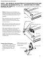
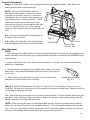
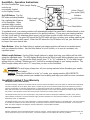
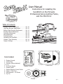
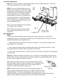
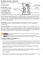
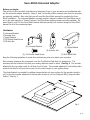
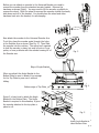
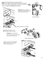
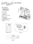
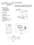
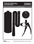
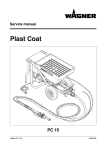
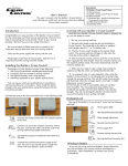
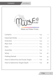
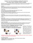
Table of Contents
User Manual
Wooden Quilting Frames
Display Console Attachment. . . . . . . . . Pg.
Top Plate Encoder Attachment . . . . . . . Pg.
Bottom Plate Encoder Attachment . . . . Pg.
Encoder Wheel Attachment . . . . . . . . . Pg.
Controller Attachment . . . . . . . . . . . . . Pg.
Wire Attachment. . . . . . . . . . . . . . . . . Pg.
Troubleshooting . . . . . . . . . . . . . . . . . Pg.
Operating the SureStitch . . . . . . . . . . . Pg.
Limited 1 Year Warranty. . . . . . . . . . . . Pg.
Jumper Settings . . . . . . . . . . . . . . . . . Pg.
3
3
4
4
5
5
6
7
7
8
Pinnacle Quilting Frames
Display Console Attachment. . . . . . . . . Pg.
Top Plate Encoder Attachment . . . . . . . Pg.
Bottom Plate Encoder Attachment . . . . Pg.
Encoder Wheel Attachment . . . . . . . . . Pg.
Controller Attachment . . . . . . . . . . . . . Pg.
Wire Attachment. . . . . . . . . . . . . . . . . Pg.
Troubleshooting . . . . . . . . . . . . . . . . . Pg.
Operating the SureStitch . . . . . . . . . . . Pg.
Limited 1 Year Warranty. . . . . . . . . . . . Pg.
Jumper Settings . . . . . . . . . . . . . . . . . Pg.
10
10
11
11
12
12
13
14
14
15
Accessory for other quilting frames
Uiversal Adaptor . . . . . . . . . . . . . . . . . Pg. 16 - 19
Pg. 1
User Manual for installation
on Wooden Quilting Frames
Table of Contents
Display Console Attachment. . . . . . . . . Pg.
Top Plate Encoder Attachment . . . . . . . Pg.
Bottom Plate Encoder Attachment . . . . Pg.
Encoder Wheel Attachment . . . . . . . . . Pg.
Controller Attachment . . . . . . . . . . . . . Pg.
Wire Attachment. . . . . . . . . . . . . . . . . Pg.
Troubleshooting . . . . . . . . . . . . . . . . . Pg.
Operating the SureStitch . . . . . . . . . . . Pg.
Limited 1 Year Warranty. . . . . . . . . . . . Pg.
Jumper Settings . . . . . . . . . . . . . . . . . Pg.
3
3
4
4
5
5
6
7
7
8
Parts Included:
1: Display Console
1: Control Box
2: Encoder (Wires attached)
(Not Shown)
1:
1:
1:
6:
2:
2:
5v Power Supply
Display Cable
Sewing Machine Control Cable
Velcro - Cable Ties
Self Adhesive - Tie Mount
Zip Tie
Display Console
Encoder
Control Box
Pg. 2
SureStitch - Assembly
Display Console Attachment
Step 1: Secure the Display Console to your quilting frame with the included velcro strap.
Place the Display Console so that it’s controls will be easily accessible while you are quilting.
(NOTE: Wait to attach all wires until Step 5.)
Step 1
Step
Step
Step
Step
1:
2:
3:
4:
Display Console
Top Plate Encoder
Bottom Plate Encoder
Controller
Step 4
Fig. 1
Step 2
Step 3
Top Plate Encoder Attachment
Step 2-1: If your sewing machine is in place on the carriage, remove it before continuing.
You will also need to turn the top plate up-side down, to be able to access the supporting
hardware.
2-2: Remove one of the front wheels from the top plate before attaching the encoder.
(Attach this encoder to the same side of the carriage that you will attach the Controller, in Step
4, to keep wires more organized.)
2-3: Remove the 6mm Hex nut, and the first washer from the encoder with the shorter bolt
through the wheel (25mm).
2-4: Place the exposed end of the bolt on the Encoder through the hole that the wheel that
you just removed, was in.
2-5: Apply the Washer, and 6mm nut back onto the bolt. Tighten the nut securely. When
you tighten the nut, make sure that the encoders moving parts don’t contact any part of the
carriage. When the top plate is sitting upright, the encoder should be angled up slightly, so
that the encoder’s wheel doesn’t touch the track on the Bottom Plate. (See Fig. 1).
6mm Hex nut
Washer
Encoder with 25mm bolt
Fig. 2
Pg. 3
Bottom Plate Encoder Attachment
NOTE: THE WHEELS ON ONE END OF THE BOTTOM PLATE ARE
ATTACHED AS SHOWN IN Fig. 3-1. REMOVE ONE OF THESE
WHEELS IN STEP 3-1. The wheels attached to the other end of the Bottom Plate can’t be
used to attach an encoder.
Step 3-1: Remove one of the wheels from
the bottom plate before attaching the encoder.
(Attach this encoder to the opposite side of the
carriage as you attached the encoder on the
top plate.)
3-2: Remove the 6mm Hex nut, and the first
washer from the remaining encoder. This
encoder should have the longer bolt through
the wheel (40mm).
Phillips Head Screw
Fig. 3-1
6mm Hex Nut
Washer
Encoder with 40mm bolt
3-3: Place the exposed end of the bolt on the
Encoder through the hole that the wheel that
you just removed, was in. Fig. 3-2
3-4: Apply the Washer, and 6mm nut back
onto the bolt. Tighten the nut securely.
When you tighten the nut make sure that the
encoders moving parts don’t contact any part of
the carriage. When the bottom plate is sitting
upright, the encoder should be angled up
slightly, so that the encoder wheel won’t touch
the Table Track..
Encoder Wheel Attachment
This section is provided so you can
properly attach a wheel to your
encoder, if you ever need to put
a wheel onto the encoder. The
process is identical for any bolt
used.
Fig. 3-2
Slide Encoder up, to allow
Encoder Wheel to fit into
Carriage Wheel
6mm Hex Bolt
CarriageWheel
Washer
Pg. 4
Controller Attachment
Step 4-1: Place your bottom, and top plates back onto your quilting machine. Also, Place your
sewing machine back onto the carriage.
NOTE: One end of all SureStitch wires are
attached to the Controller. Determine a place
to mount the Controller where it, or the wires
attached to it do not obstruct other features on
your quilting frame, or sewing machine. (Ideal
locations to mount the Controller are on the
lower portion of one of the carriage handles (see
Fig. 4), or directly to the back of your sewing
machine, other locations may also work better for
you.)
4-2: Remove the backing from the adhesive on
the back of the Controller.
4-3: Adhere the Controller to the location that
you have determined to be the most convenient.
Fig. 4
Controller
Tie Mount
Bottom Plate
Encoder Wire
Wire Attachment
NOTE:
• When wiring the SureStitch make sure that your sewing machine is turned off, and unplugged from
power, (this will ensure that when your sewing machine is turned on and accept the SureStitch as it’s
speed control).
• Leave a little slack in the wires near the wire connectors, to prevent the connector from being
pulled out, or damaged.
• Secure wires to carriage with the included velcro straps, tie mounts,
and zip ties. Keep wires taut between the velcro straps, and keep the
wires neat.
• When there is more wire than you need, coil up the extra wire,
and secure it to the carriage out of the way.
Display Wire Connector
Fig. 5-1
Step 5-1: Attach the Display wire (See Fig. 5-1, and Fig 5-2) to the Display Console, and to the
Controller. Be sure to line up the pins in the connectors to prevent bending them. Secure the wire to
the carriage to keep the wire neat.
5-2: Attach the wires from each of the encoders to the controller. It doesn’t matter which wire goes
into either of the (Telephone Type) connectors. Secure the encoder wires to the carriage using Tie
Mounts, and Zip Ties to keep the wires neat.
NOTE: When securing the wires for the bottom plate encoder, be sure to include enough slack to
allow your top plate to travel it’s entire available distance. This will prevent damage to the encoder
wire. Also, use a tie mount to secure the encoder wire to the bottom plate to prevent the wire from
rubbing on the quilting machine table when the carriage is being moved.
Pg. 5
Wiring Diagram
To Sewing Machine
Display
3 Prong Plug
Viking, PFAFF,
Janomi 1600
Power Supply
(Appearance may vary)
Control Box
1 Prong Plug
All other compatible
Sewing Machines
Note: You will recieve one (1) of the cords
shown above depending on the model of
sewing machine that your have.
Encoders
Fig. 5-2
5-3: Connect the sewing machine control wire to the Controller, and also to the location on
your sewing machine where the foot pedal attaches.
5-4: Plug your sewing machine into an available power outlet, but do not turn on your sewing
machine. Connect the 5 volt power supply to the Controller. Plug the 5 volt power supply
into an available power outlet. (The power supply needs to be connected to a cord that is
long enough to allow the carriage to travel the entire length of the quilting frame.) It is OK to
leave the SureStitch connected to a power source, when not in use. If you do disconnect the
SureStitch from power, be sure to re-attach the unit to power before turning on your sewing
machine.
5-5: Verify that all wires are correctly attached. When the SureStitch is first connected to
power, the LED panel on the display should show a number 5.
Troubleshooting
If you are experiencing problems.
T-1:
T-2:
T-3:
T-4:
Turn the sewing machine off.
Pull power cord out of SureStitch control box.
Plug power cord back into SureStitch.
Turn sewing machine on.
Because of your sewing machine’s built-in safety features, sometimes the machine will not
respond to your movement of the carriage and needs to be reset.
If your machine is running at an unusually slow speed, reset your machine and SureStitch
using the following steps.
T2-1:
T2-2:
T2-3:
T2-4:
T2-5:
Turn sewing machine off.
Unplug sewing machine from the wall, wait 5 seconds, and plug back in.
Pull power cord out of SureStitch control box.
Plug power cord back into SureStitch.
Turn sewing machine back on.
Pg. 6
SureStitch - Operation Instructions
All of the SureStitches Stitch Length Display
controls are
conveniently located
on the Display Console.
Active (Green)/
Over-speed (Red)
Indicator
On/Off Button: The On/
Off button activates/disables
Stitch Length
On/Off Button
the regulated stitch feature
Buttons
of the SureStitch. When
regulated stitch is active,
Pulse Button
the green LED light directly
above the button will be lit.
In regulated mode, your sewing machine will automatically adjust the speed that it stitches based on how
fast you move your sewing machine around on the quilting machine. If you move your sewing machine
too fast, it will reach it’s maximum stitch speed, and no longer be able to stitch fast enough to keep a
constant stitch size. The green LED above the On/Off button will turn red when your sewing machine has
reached it’s maximum stitch speed. When the LED above the On/Off button is lit red, your stitches will
be longer than your desired size.
Pulse Button: When the Pulse button is pushed your sewing machine will sew at a constant speed,
until you release the button. Use the Pulse button to tie off a stitch, or to sew at a constant, nonregulated speed.
Stitch Length Buttons: Use the Stitch Length buttons to adjust how long your stitches will be while
using the regulated mode. The LED display directly above the Stitch Length buttons displays your current
Stitch Length setting. You can set the Stitch Length from “1” to “10”, indicated by “0”, the stitch length
setting does not indicate “Stitches per inch”, but will be consistent based on your sewing machine. The
Stitch Length setting will be set to “5” every time you turn on the SureStitch.
WARNING! To avoid injury, always turn off your sewing machine before threading your needle,
or changing your bobbin.
Caution: When the SureStitch is in the “on” mode, your sewing machine WILL BEGIN TO
STITCH! This helps prevent your needles from breaking and helps your stitch be more consistent.
SureStitch Limited 1 Year Warranty
SureStitch Limited 1 Year Warranty
The Grace Company, warrants to the original end user customer that the SureStitch is free from defects in material and workmanship.
The Grace Company will, at its option, either repair or replace any part of the SureStitch system that proves defective by reason of
improper workmanship or materials. Repaired parts or replacement products will be provided by The Grace Company on an exchange
basis, and will be either new or refurbished to be functionally equivalent to new. If The Grace Company is unable to repair or replace
the product, it will refund the current value of the product at the time the warranty claim is made.
This limited warranty does not cover any damage to this product that results from improper installation, accident, abuse, misuse,
natural disaster, insufficient or excessive electrical supply, abnormal mechanical or environmental conditions, or any unauthorized
disassembly, repair, or modification.
This limited warranty covers only repair, replacement or refund for defective SureStitch devices, as provided above. The Grace Company
is not liable for, and does not cover under warranty, any damage caused to machinery attached to the SureStitch. In the event of a
claim, The Grace Company’s sole obligation shall be replacement of the SureStitch hardware.
Warranty Registration:
Warranty registration must be postmarked within 30 days of purchace. Please complete the included warranty registration card, and
mail it, along with a copy of your sales recipt to: The Grace Company, P.O. Box 27823, Salt Lake City, UT 84127
Pg. 7
Your SureStitch has been preset to configuration #1, if you have a sewing machine other than those
listed for the #1 configuration, place jumpers in the indicated locations for the configuration that lists
your sewing machine model.
If you own a Brother 1500, or Baby Lock QC Pro you will need a different model of the SureStitch.
If you sewing machine model is not listed please call The Grace Company at 1-800-264-0644 to see if
there is a model of the SureStitch that will work with your machine.
#1
Janome 1600
Pfaff Grand Quilter
Viking Mega Quilter
JP2
JP2
JP1
JP1
JP2
JP1
JP2
JP1
#4
Juki TL98E
JP2
Janome 6500, 6600,
Elna 7200
JP2
JP1
JP1
#3
#2
Juki TL98Q, TL98QE
JP2
JP1
JP2
JP1
Pg. 8
User Manual
Instructions for installing the
SureStitch on the Pinnacle
Professional Series Quilting Frame,
and the Mini-Pinni.
Table of Contents
Display Console Attachment. . . . . . . . . Pg.
Top Plate Encoder Attachment . . . . . . . Pg.
Bottom Plate Encoder Attachment . . . . Pg.
Encoder Wheel Attachment . . . . . . . . . Pg.
Controller Attachment . . . . . . . . . . . . . Pg.
Wire Attachment. . . . . . . . . . . . . . . . . Pg.
Troubleshooting . . . . . . . . . . . . . . . . . Pg.
Operating the SureStitch . . . . . . . . . . . Pg.
Limited 1 Year Warranty. . . . . . . . . . . . Pg.
Jumper Settings . . . . . . . . . . . . . . . . . Pg.
10
10
11
11
12
12
13
14
14
15
Parts Included:
1: Display Console
1: Control Box
2: Encoder (Wires attached)
(Not Shown)
1:
1:
1:
6:
2:
2:
Display Console
5v Power Supply
Display Cable
Sewing Machine Control Cable
Velcro - Cable Ties
Self Adhesive - Tie Mount
Zip Tie
Encoder
Control Box
Pg. 9
SureStitch - Assembly
Display Console Attachment
Step 1: Secure the Display Console to your quilting frame with the included velcro strap.
Place the Display Console so that it’s controls will be easily accessible while you are quilting.
(NOTE: Wait to attach all wires until Step 5.)
Step
Step
Step
Step
1:
2:
3:
4:
Display Console
Top Plate Encoder
Bottom Plate Encoder
Controller
Step 3
Step 1
Step 2
Step 4
Top Plate Encoder Attachment
Step 2-1: If your sewing machine is in place on the carriage, remove it before continuing.
You will also need to turn the top plate up-side down, to be able to access the supporting
hardware.
2-2: Remove one of the front wheels from the top plate before attaching the encoder.
(Attach this encoder to the same side of the carriage that you will attach the Controller, in Step
4, to keep the wires more organized.)
2-3: Remove the 6mm Hex nut, and the first washer from the encoder with the shorter bolt
through the wheel (25mm).
2-4: Place the exposed end of the bolt on the Encoder through the hole that the wheel that
you just removed, was in.
2-5: Apply the Washer, and 6mm nut back onto the bolt. Tighten the nut securely. When
you tighten the nut, make sure that the encoders moving parts don’t contact any part of the
carriage. When the top plate is sitting upright, the encoder should be angled up slightly, so
that the encoder’s wheel doesn’t touch the track on the Bottom Plate. (See Fig. 1)
Encoder with 25mm bolt
Washer
6mm Hex nut
Fig. 2
Pg. 10
Place encoder on one of
the wheels with bearings
on the inside carriage edge
6mm Hex Nut
Bottom Plate Encoder Attachment
Step 3-1: Remove one of the wheels from
the bottom plate before attaching the encoder.
(Attach this encoder to the opposite side of the
carriage as you attached the encoder on the
top plate.)
Fig. 3-1
Washer
3-2: Remove the 6mm Hex nut, and the first
washer from the remaining encoder. This
encoder should have the longer bolt through
the wheel (40mm).
3-3: Place the exposed end of the bolt on the
Encoder through the hole that the wheel that
you just removed, was in. Fig. 3-1
Encoder with 40mm bolt
3-4: Apply the Washer, and 6mm nut back
onto the bolt. Tighten the nut securely.
When you tighten the nut make sure that the
encoders moving parts don’t contact any part of
the carriage. When the bottom plate is sitting
upright, the encoder should be angled up
slightly, so that the encoder wheel won’t touch
the Track.
Encoder Wheel Attachment
This section is provided so you can
properly attach a wheel to your
encoder, if you ever need to put a
wheel onto the encoder. The process
is identical for any bolt used.
Tie Mount can be
places on bottem
edge
Slide Encoder up, to allow
Encoder Wheel to fit into
Carriage Wheel
6mm Hex Bolt
CarriageWheel
Washer
Pg. 11
Controller Attachment
Step 4-1: Place your bottom, and top plates back onto your quilting machine. Also, Place
your sewing machine back onto the carriage.
NOTE: One end of all SureStitch wires are
attached to the Controller. Determine a place
to mount the Controller where it, or the wires
attached to it do not obstruct other features
on your quilting frame, or sewing machine.
(Ideal locations to mount the Controller are
on the lower portion of one of the carriage
handles (see Fig. 4), or directly to the back
of your sewing machine, other locations may
also work better for you.)
4-2: Remove the backing from the adhesive
on the back of the Controller.
Fig. 4
4-3: Adhere the Controller to the location
Bottom Plate
that you have determined to be the most
Encoder Wire
convenient.
Controller
Wire Attachment
NOTE:
• When wiring the SureStitch make sure that your sewing machine is turned off, and
unplugged from power, (this will ensure that when your sewing machine is turned on, it will
accept the SureStitch as it’s speed control).
• Leave a little slack in the wires near the wire connectors, to prevent the connector from
being pulled out, or damaged.
• Secure wires to carriage with the included velcro straps, tie mounts, and zip ties. Keep
wires taut between the velcro straps, and keep the wires neat.
• When there is more wire than you need, coil up the extra wire, and secure it to the carriage
out of the way.
Step 5-1: Attach the Display wire (See Fig. 5-1, and Fig 5-2) to the Display Console, and to
the Controller. Be sure to line up the pins in the connectors to prevent bending them. Secure
the wire to the carriage to keep the wire neat.
5-2: Attach the wires from each of the encoders to the controller.
It doesn’t matter which wire goes into either of the (Telephone Type)
connectors. Secure the encoder wires to the carriage using Tie
Mounts, and Zip Ties to keep the wires neat.
Display Wire Connector
Fig. 5-1
NOTE: When securing the wires for the bottom plate encoder, be
sure to include enough slack to allow your top plate to travel it’s entire
available distance. This will prevent damage to the encoder wire. Also,
use a tie mount to secure the encoder wire to the bottom plate to prevent the wire from
rubbing on the quilting machine table when the carriage is being moved.
Pg. 12
Wiring Diagram
To Sewing Machine
3 Prong Plug
Display
Viking, PFAFF, Janomi,
Baby Lock
Power Supply
(Appearance may vary)
Control Box
Encoders
Fig. 5-2
5-3: Connect the sewing machine control wire to the Controller, and also to the location on
your sewing machine where the foot pedal attaches.
5-4: Plug your sewing machine into an available power outlet, but do not turn on your sewing
machine. Connect the 5 volt power supply to the Controller. Plug the 5 volt power supply into
an available power outlet. (The power supply needs to be connected to a cord that is long
enough to allow the carriage to travel the entire length of the quilting frame.) It is OK to leave
the SureStitch connected to a power source. If you do disconnect the SureStitch from power,
be sure to re-attach the unit to power before turning on your sewing machine.
5-5: Verify that all wires are correctly attached. When the SureStitch is first connected to
power, the LED panel on the display should show a number 5.
Troubleshooting
If you are experiencing problems.
T-1:
T-2:
T-3:
T-4:
Turn the sewing machine off.
Pull power cord out of SureStitch control box.
Plug power cord back into SureStitch.
Turn sewing machine on.
Because of your sewing machine’s built-in safety features, sometimes the machine will not
respond to your movement of the carriage and needs to be reset.
If your machine is running at an unusually slow speed, reset your machine and SureStitch
using the following steps.
T2-1:
T2-2:
T2-3:
T2-4:
T2-5:
Turn sewing machine off.
Unplug sewing machine from the wall, wait 5 seconds, and plug back in.
Pull power cord out of SureStitch control box.
Plug power cord back into SureStitch.
Turn sewing machine back on.
Pg. 13
SureStitch - Operation Instructions
All of the SureStitches Stitch Length Display
controls are
conveniently located
on the Display Console.
Active (Green)/
Over-speed (Red)
Indicator
On/Off Button: The On/
Off button activates/disables
Stitch Length
On/Off Button
the regulated stitch feature
Buttons
of the SureStitch. When
regulated stitch is active,
Pulse Button
the green LED light directly
above the button will be lit.
In regulated mode, your sewing machine will automatically adjust the speed that it stitches based on how
fast you move your sewing machine around on the quilting machine. If you move your sewing machine
too fast, it will reach it’s maximum stitch speed, and no longer be able to stitch fast enough to keep a
constant stitch size. The green LED above the On/Off button will turn red when your sewing machine has
reached it’s maximum stitch speed. When the LED above the On/Off button is lit red, your stitches will
be longer than your desired size.
Pulse Button: When the Pulse button is pushed your sewing machine will sew at a constant speed,
until you release the button. Use the Pulse button to tie off a stitch, or to sew at a constant, nonregulated speed.
Stitch Length Buttons: Use the Stitch Length buttons to adjust how long your stitches will be while
using the regulated mode. The LED display directly above the Stitch Length buttons displays your current
Stitch Length setting. You can set the Stitch Length from “1” to “10”, indicated by “0”, the stitch length
setting does not indicate “Stitches per inch”, but will be consistent based on your sewing machine. The
Stitch Length setting will be set to “5” every time you turn on the SureStitch.
WARNING! To avoid injury, always turn off your sewing machine before threading your needle,
or changing your bobbin.
Caution: When the SureStitch is in the “on” mode, your sewing machine WILL BEGIN TO
STITCH! This helps prevent your needles from breaking and helps your stitch be more consistent.
SureStitch Limited 1 Year Warranty
SureStitch Limited 1 Year Warranty
The Grace Company, warrants to the original end user customer that the SureStitch is free from defects in material and workmanship.
The Grace Company will, at its option, either repair or replace any part of the SureStitch system that proves defective by reason of
improper workmanship or materials. Repaired parts or replacement products will be provided by The Grace Company on an exchange
basis, and will be either new or refurbished to be functionally equivalent to new. If The Grace Company is unable to repair or replace
the product, it will refund the current value of the product at the time the warranty claim is made.
This limited warranty does not cover any damage to this product that results from improper installation, accident, abuse, misuse,
natural disaster, insufficient or excessive electrical supply, abnormal mechanical or environmental conditions, or any unauthorized
disassembly, repair, or modification.
This limited warranty covers only repair, replacement or refund for defective SureStitch devices, as provided above. The Grace Company
is not liable for, and does not cover under warranty, any damage caused to machinery attached to the SureStitch. In the event of a
claim, The Grace Company’s sole obligation shall be replacement of the SureStitch hardware.
Warranty Registration:
Warranty registration must be postmarked within 30 days of purchace. Please complete the included warranty registration card, and
mail it, along with a copy of your sales recipt to: The Grace Company, P.O. Box 27823, Salt Lake City, UT 84127
Pg. 14
Your SureStitch has been preset to configuration #1, if you have a sewing machine other than those
listed for the #1 configuration, place jumpers in the indicated locations for the configuration that lists
your sewing machine model.
If you own a Brother 1500, or Baby Lock QC Pro you will need a different model of the SureStitch.
If you sewing machine model is not listed please call The Grace Company at 1-800-264-0644 to see if
there is a model of the SureStitch that will work with your machine.
#1
Janome 1600
Pfaff Grand Quilter
Viking Mega Quilter
JP2
JP2
JP1
JP1
JP2
JP1
JP2
JP1
#4
Juki TL98E
JP2
Janome 6500, 6600,
Elna 7200
JP2
JP1
JP1
#3
#2
Juki TL98Q, TL98QE
JP2
JP1
JP2
JP1
Pg. 15
Sure-Stitch Universal Adaptor
Before you begin:
Take a look at the sure-stitch instructions to determine if any of your encoders can be attached without the universal adaptor brackets. Steps 2, and 3 of the Sure-Stitch manual show how the encoders
are typically installed. Also note that you will need the Sure-Stitch manual to complete the SureStitch installation. The Universal Adaptor is simply another method to attach the Sure-Stitch encoders to the vast majority of “Grace Company” and Non-Grace quilting frames currently available. Replace Steps 2, and 3 in the Sure-Stitch manual with this manual, but continue using the Sure-Stitch
manual for all of the remaining steps.
Hardware:
2)
2)
1)
2)
2)
Universal Bracket
Encoder Arm
Angle Bracket
M5 Socket Head Screw
M5 Hex Nut
(2) Universal Bracket
(1) Angle Bracket
(2) Encoder Arm
(2) #10 Nylock Nut
(2) #10 Socket Head Screw
Keep the following guidelines in mind when determining where to attach your encoders.
Each encoder measures the movement from the Top/Bottom Plate that it is attached to. The
encoders tell the controller how fast your sewing machine needs to stitch. See Fig. 1 The encoder
attached to the top plate needs to roll from front to back. The encoder attached to the bottom plate
needs to be able to roll from side to side, for the entire length of your quilting frame.
The Angle Bracket is provided for quilting frames that do not have a place for the encoder wheel to
roll, to give the encoder attached to the top plate a place to roll on.(Origional GMQ, Origional Little
Gracie). See Fig. 2
Bottom Plate
Top Plate
Fig. 1
Pg. 16
Before you can attach an encoder to the Universal Bracket you need to
remove the encoder from the standard encoder bracket. Remove the
hardware as shown (Right). You may need to lift the encoder up slightly to
remove the wheel. After the wheel is removed the encoder should now easily
slide down and off of the bracket. You should place the wheel and other
hardware back onto the bracket, for safe keeping.
Fig. 2
Now attach the encoder to the Universal Encoder Arm.
To do this, place the encoder posts through the holes
in the Encoder Arm as shown (See Fig. 3). Then Slide
the encoder into the notches. The spring isn’t required
to hold the encoder in place, but may be put on if you
prefer, or have problems with the encoder coming off of
the Encoder arm.
Fig. 3
Edge of Angle Bracket
When you attach the Angle Bracket to the
Bottom Plate be sure to attach it low enough
for the Top Plate to pass over it without
hitting.
Bottom edge of Top Plate
Fig. 4
Figure 5, shows how to attach the Angle
Bracket to the Bottom Plate. The Angle
Bracket is required in this situation, it gives
the encoder attached to the top plate a
place to roll.
Fig. 5
Attach Angle Bracket to
side of Bottom Plate
Pg. 17
Assemble the Top Plate encoder as shown in Fig. 6.
NOTE: It is critical that you have the Top Plate in it’s furthest
back position, with the sewing machine in place, and the take-up
rail in place (before attaching the encoder).
Attention: Do not tighten
Nylock nut completely. Encoder
Arm needs to pivot freely.
Fig. 6
Top Plate Encoder
Fig. 7
Encoder Attached to Top Plate
Assemble the Encoder for the
Bottom Plate as shown in Fig. 8.
Attention: Do not tighten
Nylock nut completely. Encoder
Arm needs to pivot freely.
Fig. 8
Bottom Plate Encoder
Attach the encoder to the Bottom
plate so that it rolls on the track
that the Carriage rolls on.
Fig. 9
Pg. 18
There are many other possible ways to attach
the Sure-Stitch to a quilting frame. If you don’t
see a picture matching your type of Frame in
this manual, there is still very likely a way to
attach the encoders. (See Right)
Quilting Frame without continous table.
Quilting Frame with continous Table
Pg. 19