1
Aids to Navigation
5-1
CHAPTER
5
An incorrectly identified mark is a
hazard, not an aid, to navigation.
Alton B. Moody
Aids to Navigation
Introduction and Overview
According to accepted NOAA Nautical
Chart Manual nomenclature, an Aid to Navigation (ATON)
...is a man-made structure/device external to a craft designed to assist in determining the crafts position or a safe
course or to warn of dangers or obstructions. When the information is transmitted by light waves, the device is a visual
aid to navigation; if by sound waves, an
audible aid to navigation; if by radio
waves, a radio aid to navigation. Any aid
to navigation using electronic equipment, whether or not radio waves are
involved, may be considered an electronic aid to navigation. The term aid
to navigation should not be confused
with the more general term navigational aid which covers any instrument,
device, chart, method, etc., intended to
assist in the navigation of a craft.
A more complete list of ATONs and associated
information normally found on nautical charts
is provided later in this chapter. Briefly, however, ATONs include such objects as buoys,
lights, fog signals, daybeacons, range markers,
radiobeacons and LORAN-C and Omega lattices. Although the GPS certainly satisfies the
definition of an ATON, this system is not discussed in this chapter, because GPS information is not provided on nautical charts. Omega
is also not discussed in this manual even
though Omega information is provided on certain nautical charts because small craft are not
generally equipped with these receivers. Finally, charted LORAN-C information is not included in this manual because this is covered
at length in the USCG LORAN-C User Handbook, to which the reader is referred.
ATONs may be fixed (land-based or fixed
structures in the water) or floating (e.g.,
buoys). Landmarks are the functional equivalent of ATONs but, because these have not
been especially constructed for this purpose,
are not formally classified as ATONs. Landmarks are treated in a separate chapter
(Chapter 6. Landmarks) of this manual.
This chapter provides information on the
type and utility of ATONs and how these are
depicted on nautical charts. (Because ATONs
are so important to safe navigation and, therefore, charted in great detail, this chapter is long
and detailed.) The chapter also identifies the
sources of additional information (e.g., the
Chart No. 1, U.S. Coast Pilot and the Light List)
which supplement that provided on the nautical chart. As appropriate, practical comments
are made throughout the chapter on the correct
use of ATONs for marine navigation. (See also
5-2
Chapter 6 for additional perspectives applicable
to ATONs as well as landmarks.) Numerous references are given at the end of this chapter for
those interested in additional detail. Names
enclosed in parentheses (e.g., Bowditch) denote
particularly pertinent references. The Glossary
in appendix A provides definitions of key terms
related to ATONs.
Brief Historical Asides
As might be expected, what are now called
ATONs have a long history (see, e.g.,
Bowditch, Naish). As the later history of
ATONs may be familiar to readers of this
manual, it is interesting to provide some brief
asides on the early periods. Towers (used
originally as landmarks, and later as lighthouses) were reportedly constructed to aid
passage along the Mediterranean coast as
early as 660 B.C. Between 283 and 277 B.C.,
Sostratus of Cnidus built a large (500 ft) structure on the island of Pharos which marked
the harbor of Alexandria from the north. The
Romans established a network of fire towers
along the Mediterranean.
By medieval times, beacons and range markers were in use to facilitate entrance to the ports
of Genoa and Pisa. In the so-called Dark Ages in
Europe, hermits and monks located on remote
islands and promontories displayed light signals
in chapels and participated in salvage operations
for wrecked vessels. (Today this might be viewed
as a conflict of interest!)
The organization of the Hanseatic League not
only provided for economic cooperation but also
advanced the use of ATONs (and mechanisms
for collecting what would now be termed user
fees) for navigation. A surviving chart of the approaches to Bruge dating from about 1500 A.D.
shows buoys as well as towers. (A seamans
manual of 1295 A.D. refers to buoys marking the
river channels to Seville.) In England, Trinity
House was established in the early 1500s as a
pilotage authority charged with (among other
things) the responsibility of constructing and
maintaining marks on the land.
By the 1700s ATONs had become relatively
sophisticated and widespread. The first recorded range marks in America were two light
towers placed in line on Plumb Island to mark
NOAA Chart User's Manual
the channel to Newburyport, MA, on the
Merrimack River.
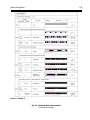
Importance of ATONs in Coastal
Navigation
As with landmarks, ATONs are charted objects used for determining LOP (e.g., with a
hand-bearing compass or radar or by direct
plotting in the case of range markers) and
curves of position (e.g., circles of position with
an optical range finder for ATONs with charted
height information, such as certain lights or hyperbolas of position with LORAN-C) so as to
determine a fix or estimated position for the
vessel. ATONs also mark hazards to navigation,
identify the limits to safe channels, designate
special-use areas (quarantine and anchorages),
and provide other relevant information. Table
51 provides both general and specific illustrations of how information derived from ATONs
can be used for marine navigation. ATONs can
be used to fix the vessels position, to serve as
homing or tracking aids, to ensure that the vessel remains clear of dangerous waters (e.g., by
using danger bearings, danger circles, or passing on the safe side of buoys) to identify turn
points, and for a variety of specialized purposes
such as compass calibration or (less frequently
with ATONs) to determine whether or not the
vessels anchor is dragging.
Importance of Positive Identification and
Related Matters
Before discussing the various types of
ATONs, charting practices, and related matters, it is appropriate to emphasize several key
points noted throughout this manual.
The mariner should be fully familiar with the charting conventions
employed to depict ATONs. And important textual material (e.g., Chart
No. 1, and the appropriate USCG
Light List) should be readily available for reference.
Any observed ATON (or landmark)
should be positively identified by the
mariner prior to its use for navigation. Published texts (e.g., Cahill,
Aids to Navigation
5-3
Table 5-1
Utility of ATONs Shown on Nautical Chart
GENERAL:
•
Used for determining range or bearing by visual means (or radar) in coastal waters so as to
determine a fix or estimated position;
SPECIFIC ILLUSTRATIONS:
•
Used for determination of fix, running fix, estimated position, set and drift of current;
•
Used for plotting danger bearings, danger circles, horizontal danger angles;
•
Used (in conjunction with danger bearing or circle) for evaluation of vessel’s position with
respect to unobservable hazards to navigation;
•
Used to determine a safe course which avoids unobservable hazards to navigation;
•
Used for establishing vessel turning bearings;
•
Used for homing or tracking purposes;
•
Used for compass calibration; and
•
(Less frequently) Used for determining whether or not an anchor is dragging.
Milligan, Maxim) and USCG accident files are replete with examples
of mishaps or accidents which resulted from the incorrect identification of an ATON. Bowditch (see references) lists failure to identify aids
to navigation as the second of 16
common errors in navigation. The
mere observation of an ATON (or
landmark) at approximately the
right position and at approximately
the right timealthough relevant
is not sufficient proof that the aid observed is the same as that shown on
the chart. ATONs are equipped with
numerous characteristics (e.g., the
flash characteristics and color of a
light, the Morse code identifier of a
radiobeacon, the number and color
of an unlighted buoy or daybeacon)
to facilitate positive identification.
Closely related to the above point,
it is important that charts (and such
publications as the Light List and
U.S. Coast Pilot) be amended as described in the latest published cor-
rections. ATONs are moved, renumbered, removed, and/or characteristics changed periodically. This can
have significant consequences (see
Cahill) for the uninformed mariner.
Bowditch also lists failure to correct charts among the common errors in navigation.
Whenever observations are taken on
any fixed ATON or landmark, this
information should be plotted on the
nautical chart by the mariner. Even
a single LOP can be useful, and frequent fixes are typically necessary
in coastal waters where ATONs are
placed. Differences between the
vessels dead reckoning position and
the plotted fix enable currents to be
estimated and/or should alert the
mariner to the possibility of other
errors.
Finally, all available means (e.g.,
maintenance of a dead reckoning
plot, use of GPS, LORAN-C, depth
sounder or other means) should be
5-4
NOAA Chart User's Manual
used for navigation. Reliance on only
one method is unprofessional and
unwise.
ATONs and Related Chart Information
(General)
This chapter includes the following
ATONs: lights, buoys, fog signals, daybeacons,
ranges, and radiobeacons. These are discussed
in order in the following sections. Brief comments on trial courses are also included in
this chapter. The symbols used in charting
these aids are illustrated in Sections P, Q, R,
and S of Chart No. 1, Nautical Chart Symbols,
Abbreviations, and Terms (Ninth Ed.) to which
the reader is referred. (Pertinent excerpts from
Chart No. 1 are included in this chapter for
ready reference.)
ATONs are placed in appropriate locations
in harbors and inland waterways to facilitate
navigation. The placement of these ATONs follow a particular pattern or convention termed
the lateral system, in which the colors, shapes,
and numbering of lights, buoys, and
daybeacons are determined by their position
in relation to safe water. (In virtually all U.S.
waters the International Association of Lighthouse Authorities (IALA) System B is followed.
Therefore, the IALA-B system is discussed in
this manual.) These designations are applied
to navigable channels proceeding from seaward toward the head (limit) of navigation. The
colors and numbers of buoys and lights along
the coasts and along traffic routes not leading
distinctly from seaward or toward headwaters
follow the same system, but applied so that
even-numbered aids mark the starboard side
when proceeding in southerly direction along
the Atlantic coast, in a northerly and westerly
direction along the gulf coast, and in a northerly direction along the Pacific coast. Table 5
2 provides a capsule summary of the characteristics of lateral aid in most U.S. waters. Additional information on buoyage systems can
be found in the Light List and other references
(e.g., Coast Guard Aids to Navigation,
Chapman).
Most ATONs used by mariners on a day-
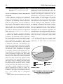
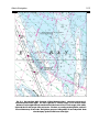
to-day basis for navigation purposes are maintained by the USCG. In 1993, there were approximately 50,500 federal ATONs in U.S. waters (Ihnat)! These aids include lights, buoys
(lighted and unlighted), daybeacons, and approximately 200 marine radiobeacons. As
shown in figure 51, the majority (51 percent)
of these ATONs are buoyslights (25 percent)
and daybeacons (24 percent) account for about
equal portions of the remainder. (Fog signals
are not included in this tabulation, as these
are typically collocated with a buoy or light.)
In addition to federally maintained ATONs,
there are approximately the same number of
privately maintained ATONs. Some privately
maintained aids are useful for navigation and
are tabulated in the Light List and shown on
nautical charts. Charting federal aids (let alone
some fraction of the private aids) and keeping
charts up to date, is obviously a large undertaking.
An ATON is charted if it is in the Light
List or is assigned a Light List number when
published in the LNM. Thus, any ATON found
/,*+76
/,*+7('%82<6
81/,*+7('%82<6
'$<%($&216
SOURCE: USCG
Fig. 5-1. Distribution of the more than 50,500
Federal ATONs in U.S. waters in 1993;
buoys are most numerous.
Aids to Navigation
5-5
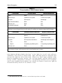
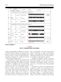
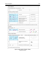
Table 5-2
Characteristics of IALA-B Lateral System
Characteristic
Port Hand Marks
Starboard Hand Marks
Color
Green
Red
Shape (buoys)
Cylindrical (can) or pillar
Conical (nun) or pillar
Daymark
Green square
Red triangle
Light color (when fitted)
Green
Red
Reflector color
Green
Red
Numbers (if numbered)
Odd
Even
At a point where a channel divides, when proceeding in the “conventional direction of buoyage,” a
preferred channel in Region B may be indicated by a modified port or starboard lateral mark as follows:
Characteristic
Preferred Channel to Starboard
Preferred Channel to Port
Color
Green with one broad red horizontal band
Red with one broad green
horizontal band
Shape (buoys)
Cylindrical (can) or pillar
Conical (nun) or pillar
Daymark
Green square, lower half red
Red triangle, lower half green
Color
Green
Red
Rhythm
Composite group flashing (2+1)
Composite group flashing (2+1)
Green
Red
Reflector color
CAUTION: When proceeding toward sea, it may not always be possible to pass on either side of preferred
channel aids to navigation. The appropriate nautical chart should always be consulted.
in the Light List will also be found on the chart.1
Additionally, some ATONs are charted which
are not in the Light List, such as those established by neighboring foreign countries, aids
having reliable maintenance authorities
(such as those established by the military), and
environmental buoys which are not included
1
in the Light List. As well, radar reflectors,
lights, and sound signals are charted for those
features (e.g., floats, targets, platforms, dredging range markers, and data collection buoys)
not specifically intended for use in navigation,
whether the feature is listed in the Light List
or not.
This assumes that the chart has been corrected based upon data in the LNM.
5-6
NOAA Chart User's Manual
ATON information provided on nautical
charts includes a symbol unique to each class
of aid and a set of characteristics such as number, height, color, and nominal range. These
characteristics are provided in labels. Symbols
and characteristics are placed so as to be
readily identified by the chart user (not obscured by less important information) and to
avoid overlap with any charted channels.
These standard symbols are reserved for
ATONs which appear in the Light List.
Charted lights and beacons not intended as
guides for normal surface navigation are
shown with a landmark symbol (see Nautical
Chart Manual, Chapter 6. Landmarks) and
identifying label. Any identifying navigational
light or beacon that is not established by the
USCG or equivalent authority is identified on
the charts either by the label Priv (for privately maintained aids) or by naming the
agency that is responsible for its maintenance.
Temporary aids are seldom charted unless
given a Light List number. ATONs established
(and/or aid characteristics that are changed)
for the winter navigation season are considered temporary aids and these (changes) are
not charted. However, specific details for important aids, such as seasonal fog signals at
major aids, are charted in all areas. A seasonal
aid note is found on all Great Lakes charts and
on east coast charts from Cape Henry, VA,
northward. This note reads as follows:
SEASONAL AIDS
During some winter months or when
endangered by ice, certain aids to navigation are replaced by other types or
removed. For details see the U.S. Coast
Guard Light List.
2
text.
Lights
According to official charting definitions
in the Desk Reference Guide, a light
is a luminous signal emitted by a fixed
structure 2 to aid navigation that marks
channels, warns of dangers or obstructions to navigation, and assists the
mariner in determining his position.
Lights are identified by their characteristics at night and by the shape and
color of their daymarks. Light characteristics include flash sequence, length
of light and dark periods, color, and
range of visibility. Lights are categorized by function (e.g., junction light,
directional light, range light, leading
light, sector light, passing light, and
aeronautical light). [Emphasis added.]
There were approximately 12,200 federally
maintained lights in U.S. waters in 1993.
Most lighted ATONs (including lights and
lighted buoys) are equipped with controls that
automatically cause the light to operate during darkness and to be extinguished during
daylight. These devices are not of equal sensitivity and, in consequence, all lights do not
come on or go off at the same time. The lighting apparatus is serviced at periodic intervals,
but there is always the possibility that the light
is extinguished or operating improperly.
Lights can be used for navigation during
the hours of daylight or darkness. During daylight, the fixed structures associated with
these lights serve as landmarks for bearing
or range determination. During daylight
hours, the identification of the light is based
upon the position of the light and its physical
appearance. (The physical appearance of a
Lighted buoys are classified by NOAA as buoys, rather than lights, and are discussed later in the main
Aids to Navigation
5-7
light structure is not found on the chart, however, as noted below.) At night, the light is
used in much the same manner except that the
identification of the light is based primarily
upon the characteristics of the light, such as
the color, flash sequence, and position.
Charting Practices
This section provides information on charting practices for lights and related information. Charting conventions consist of a light
symbol, associated labels and notes, and (for
sectored lights or where lights have obscured
sectors) information on the sector(s).
Symbol (P)
Major lights, minor lights, and lighthouses
are charted as shown in Section P of Chart No.
1. In particular, the position of the light is
shown by a black 0.75 mm dot (or open black
circle 1.0 mm in diameter in the case of an articulated light), with a magenta flare (3.4 mm
in length with a rounded end of 0.6 mm radius) drawn about 1 mm from the light dot.
This light symbol has the visual appearance
of an exclamation mark (!) in print. The flare
is generally oriented toward the label and is
drawn to avoid obscuring other relevant chart
detail. Where possible, the flare orientation
is aligned with those of neighboring buoy symbols (see below). Leading lights (i.e., those arranged, similar to range lightsexcept that
only a single light is usedto indicate a path
to be followed) may be charted with the flare
oriented seaward along the line.
Labels and Notes
The label and note(s) provide information
on the name of the light and the lights characteristics, including the light number (if any).
This information is very useful for identifying
the light and for determining whether it can
be seen from the vessels approximate position.
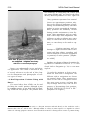
Miah Maull shoal light in Delaware Bay
Official U.S. Coast Guard photograph
If the name of the light appears in the Light
List and space permits, the name of the light
is shown in black conventional (vertical) type
above the light characteristics.3 The name may
be omitted if it is the same as the name of the
geographic feature in the immediate vicinity
and space is at a premium. Thus, for example,
if the geographic name Pt Judith were
shown in the chart, the name Pt Judith Lt
would not be given.
The characteristics of the light include its
flash characteristic, color, period, height, visibility (nominal range), and number.
Flash characteristics include the sequence
and timing of the flashes and include fixed,
occulting (single occulting, group occulting,
and composite group occulting) isophase,
3
These are shown in conventional, rather than italic type because italic type refers, among other things, to
floating structures. See also Chapter 4.
5-8
NOAA Chart User's Manual
flashing (including single flashing, group
flashing, composite group flashing, quick,
very quick, and ultra quick), Morse code (e.g.,
Morse A), fixed and flashing, and alternating. Illustrative flash characteristics and associated chart labels are shown in Section P
(10.1 to 10.11) of Chart No. 1, which is reproduced in figure 52. Although not particularly
complex, this diagram requires some study.
Study of this illustration should be supplemented with on-the-water practice in identifying the characteristics of lights. Mariners
are also cautioned that if a vessel has considerable vertical motion due to pitching in
heavy seas, a light sighted on or near the horizon may alternately appear and disappear
with the possible result that its true characteristic will not be apparent. In consequence,
the light could be misidentified. Under these
conditions, the true characteristic may not be
apparent until the vessel is closer to the light.
The watch stander should be placed at the
highest convenient station for such observation.
The color of lights is shown using standard abbreviation (e.g., R for red, G for green,
W for white, etc., as shown in Sections P 11.2
through 11.8 of Chart No. 1) following the
flash characteristics of the light. Generally,
white lights are not so labeled (and if no color
is shown, on the chart, white can be assumed)
except where a light exhibits more than one
color, in which case W is shown. Amber lights
are charted as yellow and abbreviated Y.
Although the color of a light is important to
its identification, mariners should be aware
that the apparent color of the light may
change with distance, because the various
colored lights may have different nominal
ranges (see below). Additionally, ice or snow
may cover the panes of unattended lights,
greatly reducing the visibility of lights (see
below) and may cause colored lights to appear white.
The period of a light is defined as the time
(in seconds) required to exhibit a full pattern
together with the interval between patterns.
Periods are shown on the nautical chart, to
the nearest tenth of a second expressed as a
decimal, after the flash characteristic. Mariners should time a light using a stopwatch.
To increase the precision of measurement for
lights with short periods, the aggregate time
required to complete several cycles should be
measured. Thus, for example, if 60 seconds
were required for 10 cycles, the period would
be 6 seconds.
Taken together, the flash characteristic,
color, and period provide key information necessary to identify the light when it is in operation. According to both the Admiralty Manual
of Navigation and Bowditch, the characteristics of a light must always be checked on sighting. As noted by Moody, An incorrectly identified mark is a hazard, not an aid, to navigation.
The height of the light is the vertical distance between the light source (not the top of
the light!) and the shoreline reference datum.
Height is shown in feet using the abbreviation
ft except on metric charts, where height is
shown in meters using the abbreviation m.
Height information is important for distanceoff calculations (see Bowditch) in daytime or
for estimating the distance at which a light
can be seen at night (see below). Normally, the
mariner should search for the highest lights
first when approaching a coastas these are
likely to be seen most easily. However, the
mariner should bear in mind that lights
placed at high elevations are more frequently
obscured by clouds, mist, or fog than those
lights located at or near sea level.
The visibility of the light is expressed as
the nominal range, and is charted except in
the case of range lights or privately maintained lights.4 The nominal range is the maximum distance (in nautical miles on most
charts, in statute miles on most Great Lakes
charts) a light may be seen at night in clear
The nominal range is not given in the USCG Light List either, because these are very short-range
ATONs.
4
Aids to Navigation
5-9
Source: Chart No. 1.
Fig. 5-2. Illustrative Flash Characteristics
Continued on next page
5-10
NOAA Chart User's Manual
Source: Chart No. 1.
Continued
Fig. 5-2. Illustrative Flash Characteristics
weather (meteorological visibility of 10 nautical miles) without regard for the height of the
light or the observer. For those lights with two
or more colors (see below) either both nominal ranges are shown (e.g., 15/10M) or the lesser
of the two ranges will be given.
Calculation procedures for estimating the
actual distance from which a light can be seen
at night, considering the height of the light
and observer, nominal range, and prevailing
visibility, are detailed in the Light List and
other references (e.g., Bowditch, Dutton,
Maxim). Common practice for the navigator
is to draw circles around these lights on the
chart with radius equal to the distance at
which the light is likely to be visible (see
Schlereth) and to estimate the corresponding time when these should first be seen.
These calculations are only approximate
(Burch). Nonetheless, if lights are not sighted
within a reasonable time after that predicted,
a dangerous situation may exist and the mariner should be appropriately cautious.
Finally, the assigned number or letter(s)
of the light structure (if any) are shown following the visibility, and enclosed in quotation marks. The number or letter can be observed (e.g., with binoculars) during daylight
hours.
On large-scale charts, the characteristics
of lights are shown in the following order:
flash characteristic, color, period, height, visibility, and number. For example, an 85 foot
red light (number 2) of nominal range 10
miles which exhibits a group of three flashes
within a period of 10 seconds would include
Aids to Navigation
the light symbol, light name (if appropriate)
and the label: Fl (3) R 10s 85ft 10M 2.
Small-scale charts show complete information regarding characteristics for major seacoast lights expected to be used for coastal
navigation, but may omit certain information
in cases where congestion is a problem. In this
event, characteristics are omitted in the following order: height, period, number of flashes
in groups, the number or letter on the structure, and the nominal visibility.
Sectors, and Related Matters
In some cases, terrain masking (e.g., a
mountain or island) may limit the area over
which a light may be seen. Knowledge of these
blind areas is obviously useful to mariners.
(There is, after all, no point in looking for
something that cannot be seen. Moreover, a
prudent mariner might well alter the intended track so as to avoid an obscured sector
of a major light.) An obscured sector (sometimes termed dark sector) is a portion of the
light sector of a navigational light in which the
light is not visible. Where a LNM reports its
establishment, the obscured sector (see Section P 43 of Chart No. 1) is charted with dashed
rays marking the limits of the obscured sector. Additionally a dashed arc in the sector
centered on the light indicates the obscured
sector. Directional arrows are used to mark
the points where the dashed arc intersects the
dashed ray line. A label, LT OBSC or DARK
SECTOR, is added for clarity. See figure 53
for an illustration of a light with an observed
sector taken from NOS Chart No. 13218.
In other cases, sectors are deliberately created by placing colored glass in the lanterns
of lights to provide additional information to
the mariner. Sector lights (see Sections P 40
and 42 of Chart No. 1 for symbology) are used
primarily to warn mariners of dangerous
shoals or other hazards to surface navigation.
The danger sectors are usually red and are
charted (in degrees true) from the perspective
of the mariner looking toward the light. Mariners are cautioned not to alter course based
solely on the observed sectors, but rather to
note the correct compass bearing. This is because it is difficult to determine the sector
5-11
boundaries with accuracy because the edges
of a colored sector cannot be sharply demarcated.
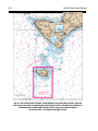
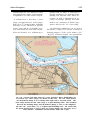
Figure 54 presents an excerpt from NOS
Chart No. 12304 which shows a red sector on
the Brandywine Shoals Light warning of
shoals in this area.
Directional Lights
Several types of directional lights are in use
(see Section P 30 of Chart No. 1 for chart conventions). These lights have a very narrow sector designed to mark a direction to be followed. The narrow sector may be flanked by
an obscured or intensified light, or by lights
of a different color or characteristic. A direc-
Fourteen Ft. Bank Light in Delaware Bay.
Note differences in appearance with
Miah Maull shown earlier.
Official U.S. Coast Guard Photograph.
5-12
NOAA Chart User's Manual
Fig. 5-3. Excerpt from NOS Chart No. 13218 (Martha’s Vineyard to Block Island). Note the
obscured sector of the Gay Head Light south of Nomans Land. The light at Gay Head is an
alternating red and white with a period of 15 seconds and a nominal range of
20 nautical miles. The height of this light is 170 ft.
Aids to Navigation
5-13
Fig. 5-4. Excerpt from NOS Chart No. 12304 (Delaware Bay). Note the red sector of
the Brandywine Shoal Light. The 60 ft. light has a nominal range of 13 nautical miles.
Reference to the Light List indicates that this is the lesser of the 17-mile range of the white
light and the 13-mile range of the red sector. The horn, according to the Light List, emits a 2second blast every 15 seconds. The light is a group occulting with a 12-second period. Note
also the riprap symbol at the base of the light.
5-14
tional light normally shows three adjoining
sectors of red, white, and green, with the center white beam oriented to mark the channel.
Leading Light
A leading light (see Section P 20 of Chart
No. 1 for chart conventions) is similar to a
range light or marker (see below) except that
it marks a channel with a single light (with
ray lines) rather than with two separate lights.
It is usually a high intensity beam marking the
safe channel which diminishes to much lower
intensities around the remainder of the horizon. It differs from a directional light (see
above) in that it shows only one color of light
instead of the three-color sectors of the directional light.
Aeronautical Lights
Aeronautical lights (see Section P 60 of
Chart No. 1 for chart conventions) are white
and green navigation lights associated with airports and often found atop the control tower.
Because these are generally attended during
their hours of operation, the lights are highly
dependable. Moreover, these are often the most
conspicuous of the nonstrobe lights and their
nominal range may be greater than those established for marine navigation. The aeronautical light is charted by a standard light dot
with magenta flare. The light symbol is accompanied by its characteristics and the label
AERO.
Articulated Lights
An articulated light is a floating light, also
called a buoyant beacon. It is basically a vertical pipe structure that oscillates around a universal coupling connected to a sinker. The light
structure (which is typically 10 feet to 15 feet
NOAA Chart User's Manual
above the water surface at high tide) is kept
upright by the buoyancy of a submerged floatation chamber. Unlike other buoys (see below)
it has no scope of chain and the light is directly over the sinker, i.e., this structure has
no watch circle. It is designed primarily to
mark narrow channels with greater precision
than conventional buoys in situations where
the depth of water, up to 60 feet, is too great
for a normal pile or dolphin light structure (see
Dutton).
When first introduced, this type of ATON,
which is neither a true buoy nor exactly a fixed
light, required a new symbol for charting (see
Section P 5 of Chart No. 1). This symbol is a
black open circle 1.0 mm in diameter (the approximate position symbol for a landmark explained in Chapter 6) centered on the published position with a magenta flare. The open
circle is chosen in lieu of a dot (used for other
fixed lights) because the structure may be displaced more than 10 feet of its true position.
The articulated light is labeled Art in Newton Medium italic type. 5
Strobe Lights
Many charted features are marked with
very quick-flashing high-intensity lights,
called strobe lights. The light is usually a xenon gas condenser-discharge flash lamp or
flash tube. Strobe lights are used on certain
USCG-maintained ATONs and on aeronautical hazards, such as stacks, towers, and buildings. ATONs published in the NM and Light
List as well as landmarks with a strobe light
include the label Strobe as well as other label elements (see above). The flash period of a
strobe light is usually (but not always) omitted because of its extremely short duration
(much less than 1 second).
The reason italics are used (in lieu of the vertical lettering found on other lights) is that articulated
lightsthough classified as fixed structuresare floating lights. Buoys are also labeled in italic type.
5
Aids to Navigation
Riprap
Riprap are mounds of broken rock, cobbles,
boulders, or fragments that are often placed
around light structures as protection against
ice damage and scouring by fast-moving currents. Desirable as the use of riprap may be
from the point of view of protecting the structureand helping to ensure the reliability of
the lightriprap also presents a hazard to
navigation for vessels that pass too close
aboard. Riprap is denoted on nautical charts
by a special symbol (see Section P a of Chart
No. 1).
Supplemental Information Regarding
Lights and Other ATONs
In addition to the nautical chart, the Light
List, the U.S. Coast Pilot, and commercial
cruising guides offer relevant information on
ATONs. Additional information provided in
these sources is briefly discussed below.
The Light List
The Light List is the authoritative source
of information on ATONs. It is published annually by the USCG in several volumes, covering various geographic areas. The Light List
is a valuable complement to the nautical chart
and provides specific information on ATONs.
Contrary to the implication of its title, the
Light List offers information on unlighted as
well as lighted ATONs. In addition to general
information regarding ATONs the Light List
includes specific information on each ATON
such as its LLNR, the name and location of the
ATON, the geographic coordinates (latitude
and longitude), characteristics, height, nominal range (for a wider variety of ATONs than
found on the nautical chart), an identification
of the structure, and pertinent remarks.
The organization of the Light List is actually quite logical, but requires some study to
be used effectively. When all else fails, the
5-15
index at the back of each volume is helpful.
Much of the information on ATONs shown
in the Light List is identical to that provided
on nautical charts. However, the Light List
does contain information not found on charts
and, additionally, is revised more frequently
than most nautical charts and, therefore, is
more likely to contain up-to-date information.
(However, a properly corrected chart is also
up to date.)
Perhaps the most useful information contained in the Light List that does not appear
in the nautical chart is a brief description of
the structure and the accompanying remarks.
The description of the structure is particularly
useful for identifying lights during daylight
conditions. For example, the route from seaward up the Delaware Bay is marked by several lighthouses, including the Brandywine
Shoal Light (see figure 54), Fourteen Foot
Bank Light, Miah Maull Shoal Light, Elbow of
Cross Ledge Light, and Ship John Shoal Light.
(Photographs in this chapter show two of these
lights.) Mariners with local knowledge can
readily identify these lights by their distinctive physical appearance. 6 However, those
without local knowledge would certainly benefit from the following descriptions taken from
the Light List, Volume II, Atlantic Coast, Toms
River, New Jersey to Little River, South Carolina (1993):
Brandywine Shoal Light-Cylindrical
concrete structure, adjacent to old
screwpile with red sector from 151 degrees to 338 degrees covering shoal
area southwest of Cape May. As with
several other lights in the area, this
light is equipped with an emergency
light of lower intensity with same characteristic as main light when main light
is extinguished.
In SAR cases on the Delaware Bay in which the distressed mariner reports a position near one of these
lights, rescue authorities often ask the mariner to describe the light. This procedure can save fruitless search
hours in cases where the distressed vessel does not have an accurate position fix and misidentifies the light.
6
5-16
Fourteen Foot Bank Light-White
tower and dwelling on black cylindrical pile.
Miah Maull Shoal Light-Red conical
tower, on gray conical pier; red cylindrical watch room and black lantern.
Elbow of Cross Ledge Light-Red skeleton tower with small white house on
international orange cylindrical base.
Ship John Shoal Light-Brown octagonal dwelling with pyramidal roof; on
cylindrical pier. Light has red sector
from 138 degrees to 321.5 degrees covers shoals on east channel. High intensity beam down Miah Maul Range.
Additionally, the Light List provides specific information on ATONs which are seasonalinformation not shown on the nautical
chart. For example, this same volume of the
Light List notes that the Deadman Shoal
Lighted Buoy IDS which is normally equipped
with a flashing green light with a 4-second
period is replaced by an unlighted winter
marker from December 15 to April 1 of each
year.
The U.S. Coast Pilot
The U.S. Coast Pilot also provides information on lights and other ATONs. The scope
of the material provided in the U.S. Coast Pilot is quite broad (see other chapters of this
manual) and, as a result, coverage of ATONs
is less complete than can be found in the Light
List. Nonetheless, the U. S. Coast Pilot does
contain useful information on selected ATONs.
In particular, the U. S. Coast Pilot often provides descriptions of lights that are useful for
identifying the light structure during daylight
hours. For example, here are a few descriptions of lights taken from the U.S. Coast Pilot
Volume 3 (1993), Atlantic Coast: Sandy Hook
to Cape Henry:
NOAA Chart User's Manual
The entrance to South River is between Saunders Point and Thomas
Point, 1.8 miles northeastward.
Thomas Point Shoal Light (38° 53.9'
N, 76° 26.2' W), 43 feet above the
water, is shown from a white hexagonal tower on piles, in depths of
5 feet near the outer end of the shoal
1.2 miles east-southeastward of the
point; a fog signal is at the light. The
light is 1.5 miles due west of a point
on the bay ship channel 124.2 miles
above the Capes. (p. 176)
Solomons Lump Light (38° 02.9' N,
76° 00.9' W), 47 feet above the water, is shown from a white octagonal dwelling, with a square tower,
on a brown cylindrical base, in
depths of 7 feet on the Smith Island
side of Kedges Straits. (p. 190)
Sharps Island Light (38° 38.3' N,
76° 22.5' W), 54 feet above the water, is shown from a leaning, brown
tower on a cylindrical pier, in 10 feet
at the north end of a shoal that
bares at the east end
. (p. 194)
[This description is particularly
valuable to those without local
knowledge. The structure actually
leans a great deal, and it is difficult
to believe that this is an ATON
when approaching from certain
angles in daylight!]
Published Guides and Other Books
Published cruising guides and other books
often have descriptions and photographs
which are useful to the mariner. Books on
lighthouses (e.g., Caldwell, de Gast, Holland),
in particular, often contain photographs which
facilitate daylight identification. These books
are not designed for navigational purposes,
however, and the appearance of the light may
have changed since the photograph was
taken. 7
Aids to Navigation
Buoys
According to the somewhat lengthy offic ial de fi nitio n in the D e s k R e f e r e n c e
Guide, a buoy
is a floating object, other than a
lightship, moored or anchored to the
bottom as an aid to navigation. Buoys
may be classified according to shape,
as spar, cylindrical or can, conical, nun,
spherical, barrel, or pillar buoy. They
may also be classified according to the
color scheme, as a red, green, or checkered buoy. A buoy fitted with a characteristic shape at the top to aid in its
identification is called a topmark buoy.
A sound buoy is one equipped with a
characteristic sound signal, and may be
further classified according to the manner in which the sound is produced, as
a bell, gong, horn, trumpet, or whistle
buoy. A lighted buoy is one with a light
having definite characteristics for detection and identification during darkness. If the light is produced by gas it
may be called a gas buoy. A buoy
equipped with a marker radiobeacon is
called a radiobeacon buoy. A buoy with
equipment for automatically transmitting a radio signal when triggered by
an underwater sound signal is called a
sonobuoy. A combination buoy has more
than one means of conveying intelligence; it may be called a lighted sound
buoy if it is a lighted buoy provided with
a sound signal. Buoys may be classified
according to location, as channel, midchannel, middle ground, turning, fairway, bifurcation, junction or sea buoy.
A bar buoy marks the location of a bar.
5-17
A buoy marking a hazard to navigation
may be classified according to the nature of the hazard, as obstruction,
wreck, telegraph, cable, fish net, dredging, or spoilground buoy. Buoys used
for particular purposes may be classified according to their use, as anchor,
anchorage, quarantine, mooring, warping, swinging, marker, station, watch,
or position buoy. A light-weight buoy
especially designed to withstand
strong currents is called a river buoy.
An ice buoy is a sturdy one used to replace a more easily damaged buoy during a period when heavy ice is anticipated.
The above definition also identifies some
of the many navigational uses of buoys. Perhaps the most significant use of a buoy is to
enable the mariner to stay in safe water and
avoid unseen hazards to navigation.
As noted, buoys are the most common
ATON. Approximately 25,500 federal buoys
marked U.S. waters in 1993. Buoys may be
lighted and/or have fog signals (see below),
but most (82 percent) are unlighted can or nun
buoys.
Physically, buoys are floating ATONs that
are moored to the seabed by concrete sinkers attached to the body of the buoy with
chain or synthetic rope of various lengths.
Buoy moorings vary in length, being sufficiently long to accommodate the water depth
where the buoy is located, plus an allowance
for variations in water depth. The mooring
lengths define a watch circle, and buoys
move within this circle depending upon wind,
current, and tidal height. The size of the
watch circle is not reflected in the chart.
As an example of this point, an attractively illustrated book (see de Gast) reprinted in 1993, contains a
dramatic photograph of the Sharps Island Light referred to above. This light (correctly described in the USCG
Light List) is leaning as a result of ice damage in 1977. The photograph of this light, unchanged since the
original 1973 edition of this book, does not reflect this damage. No doubt the light looks better in its undamaged
state, and the author did not intend to write a navigation text.
7
5-18
NOAA Chart User's Manual
ner should try to avoid fixing the vessels position using floating aids.8 As noted in the introductory material published in each Light List:
Buoy positions represented on nautical
charts are approximate positions only,
due to the practical limitations of positioning and maintaining buoys and their
sinkers in precise geographical locations.
Buoy positions are normally verified
during periodic maintenance visits. Between visits, atmospheric and sea conditions, seabed slope and composition, and
collisions or other accidents may cause
buoys to shift from their charted locations, or cause buoys to be sunk or capsized
.
More than 80 percent of buoys in U.S. waters
are unlighted. Unlighted nun buoy.
Official U.S. Coast Guard photograph.
Buoys vary substantially in size and physical appearance. The reader is directed to any
of several references at the end of this chapter for illustrations and photographs of various types of buoys.
A Brief Digression: Position Fixing with
Buoys
It is noted above that ATONs can be used
for fixing the vessels position. Although it may
be common practice to use both fixed and floating ATONs for this purpose, the prudent mari-
Prudent mariners will use
bearings or angles from fixed aids to navigation and shore objects, soundings, and
various methods of electronic navigation
to positively fix their position. [Emphasis added.]
Guidance on the use of buoys for position fixing offered in COMDTPUB P16502.8, U. S. Coast
Guard Aids to Navigation (p. 39) is even more
explicit:
In order for mariners to derive maximum use from aids to navigation, the
different aids to navigation are shown
on nautical charts. Thus, mariners are
aware of the aids to navigation which
they may expect to pass, and may plot
any bearings which they take for the
purpose of determining their position.
DO NOT USE BUOYS TO PLOT A FIX.
[Emphasis in original.]
An articulated light (see main text) is a buoyant structure tethered directly to the seabed in such a
manner that it has no watch circle. Although similar to a buoy in some respects, it is regarded as a fixed
ATON for charting purposes. However, these should be treated as floating aids in terms of position fixing.
8
Aids to Navigation
5-19
Buoys could be off-station at any time, but
are more likely to be off-station after storms,
and in icy conditions. During the severe flooding of the Midwest in the summer of 1993, for
example, it was estimated (Professional Mariner, Issue No. 3) that as many as 70 percent of
the thousands of ATONs in the area needed
to be replaced. Severe ice and snow storms in
the Northeast in the following year also re-
quired numerous buoys to be reset in the Delaware Bay and New York harbor.
It is recognized that there are circumstances where fixed ATONs may not be available for position fixing yet numerous buoys
might be present in the area. Any position
based solely on buoys should be regarded with
a healthy skepticism and verified using fixed
ATONs at the first opportunity.
Buoys can be damaged and moved off station by ice, one of the reasons
that position-fixing with buoys is not recommended. Here crew from the
USCG Red Oak work on an ice-damaged buoy.
Official U.S. Coast Guard photograph.
5-20
NOAA Chart User's Manual
Charting Practices
As with other ATONs, buoys are charted
with a symbol and one or more labels providing capsule information about the buoy. As
noted, generally only buoys listed in the Light
List are charted. In most cases this presents
no difficulty for the mariner. However, there
are numerous buoys that are not charted. In
particular, buoys marking channels along the
Atlantic coast and gulf coast that shift frequently are generally omitted. (Charting these
would require excessively frequent revisions.)
Where these buoys are not charted, a note is
added explaining that these buoys are omitted. In this case a standard note is added to
the chart:
Entrance to Inlets
The entrance channels at the inlets not
protected by jetties are subject to frequent changes. The buoys are not
charted because they are frequently
shifted in position. Buoys are removed
if shoaling makes inlets unnavigable.
Entries for such buoys in the Light List do
not contain latitude and longitude coordinates.
Note also that a given chart may omit
buoys (and other information) which are
shown on a larger scale chart of the area.
Symbols (Q)
There are numerous charting symbols used
to depict buoys of various types. Figure 55,
taken from Chart No. 1, provides a sample for
review. Chart No. 1 should be studied in some
detail to ensure familiarity with the various
buoy symbols. Refer to table 52 for guidance
on the significance of lateral aids. Definitions
of various types of buoys can be found in the
Glossary in appendix A of this manual and the
Light List. Additionally, the Light List provides an explanation of the significance of each
buoy to the mariner.
The position of a buoy is shown with a
small circle, the approximate position symbol (see Chapter 6) because of the practical
limitations in positioning and maintaining
buoys and their sinkers in accurate geographic locations. Buoys are charted, insofar
as possible, in their published position on
large-scale charts. In cases where a buoy position coincides with the symbol for another
critical feature, such as a rock awash, the
buoy may be charted slightly off position for
clarity, but always on the same azimuth as
the feature that it marks. If buoys are on opposite sides of a dredged channel and plot
less than 0.5 mm apart, the aids may be separated to 0.5 mm.
Channel buoy symbols (e.g., the diamond
shape) are generally shown at a 65° angle from
the channel lines, with the symbol pointing toward the top of the chart. Buoy symbols marking the limits of fish trap areas are oriented
so as to fall inside the area. For other buoys
the orientation of the buoy symbols is approximately 25° from the vertical with the symbol
inclined toward the label.
Lighted buoys, except superbuoys, are
charted with a magenta disk 2.5 mm in diameter, centered on the circle located at the base
of the buoy symbol. The few buoys equipped
with a RACON9 are charted with a 7.1 mm diameter magenta circle centered on the circle
located at the base of the buoy.
Superbuoys, including single point mooring buoys, oceanographic data acquisition systems buoys (ODAS), and large automated navigation buoys (LNB or LANBY), share a unique
symbol (Sections P 8 and Q 26 of Chart No. 1).
See figure 56 for an illustration.
The word RACON is derived from RAdar beaCON. A RACON produces a coded response (Morse) when
triggered by a radar signal.
9
Aids to Navigation
5-21
Fig. 5-5. An Excerpt From Chart No. 1: Buoys
Continued on next page
5-22
NOAA Chart User's Manual
Continued
Fig. 5-5. An Excerpt From Chart No. 1: Buoys
Aids to Navigation
5-23
LANBY silhouetted against rising sun.
Official U.S. Coast Guard photograph.
As a point of interest the present
LANBYsbuilt
originally
to
replace
lightshipsare now nearing the end of their
service life and are being replaced by smaller,
solar-powered exposed location buoys (ELBs).
The newer ELBs are cheaper to buy and maintain than the older diesel-powered LNBs
(Walsh).
Charted Characteristics
The characteristics of buoys include
color and shape, and, if so equipped, the
color and period of their light. Characteristics are abbreviated as shown in Chart
No. 1 (Sections Q 2 through Q 71, and a
through U) and the Light List. These characteristics are important to the mariner
for identification purposes. Indeed, as with
lights, all mariners are cautioned to establish positive identification of each buoy in
the vicinity of the vessels track. Noticeably absent from this list of characteristics are the height of the buoy and the
nominal range (if lighted). (Nominal
ranges for selected buoys can be found in
the Light List, a n d t y p i c a l l y v a r i e s f r o m
about 4- to 6-nautical miles for most lighted
buoys.)
5-24
NOAA Chart User's Manual
spherical buoy, spar buoy, or pillar buoy) and
by any audible signal they emit (bell, whistle,
gong). Buoys (with the exception of mooring
buoys) are labeled as to their color using specified abbreviations given in Chart No. 1.11 For
example, red buoys are shown with magenta
fill, labeled R, and green buoys with green
fill and labeled G.
The identifying number (or letter(s))
painted on the buoy (not the LLNR) is shown
in quotation marks, e.g., 22.
Light characteristics and period are also
presented in the label in much the same manner as noted above for lights.
Private buoys listed in the Light List are
identified with the label Priv in italic print.
The service name is charted on military
ATONs, e.g., Navy. Privately maintained
buoys not listed in the Light List are not generally charted.
A radar-enhancing structure or reflective
material has been installed on nearly all major buoys and many minor buoys. Therefore,
reference to this feature is not charted as part
of the buoys characteristics. Instead, the following note is included on the chart:
Fig. 5-6. Excerpt from NOS Chart No. 12214 (Cape
May to Fenwick Island). Note the LANBY in this
illustration. This buoy has a RACON with the
identifier (— —) as well as a light and a horn.
Buoy characteristics are shown in italic
type. 10 These labels are placed so as not to
overlap with wreck symbols, shoals, least
depths, and other critical features. Buoys are
identified on charts by their shape (can, nun,
Radar reflectors have been placed on
many floating aids to navigation. Individual radar reflector identification on
these aids has been omitted from this
chart.
On large-scale charts, the characteristics
of buoys are shown in the following standardized order; color (omit if black) shape, (if unlighted), number (or letter(s)), flash character
(if lighted), light color (if lighted), light period
(if lighted), and fog signal (if so equipped). For
example, the complete legend would be
charted as follows:
This is consistent with the convention that floating objects are shown in italics.
Black buoys are not discussed in this manual as these are being phased out.
10
11
Aids to Navigation
5-25
Lighted Buoy
Unlighted Buoy
R 22
Fl R 4s BELL
R
N 22
In congested areas and on smaller scale
charts, some of these characteristics are sometimes omitted. Characteristics of lighted buoys
are omitted in the following order: period,
color, number, light color, and flash characteristics. For unlighted buoys, the corresponding order is: color then number.
Space constraints do not permit an exhaustive discussion of the many types of buoys
found in U.S. waters. However, three of the
most common types of buoys are briefly reviewed.
Channel Buoys
These buoys mark the edges of navigable
channels. In the IALA-B system, red buoys
mark the starboard side of the channel, and
green the port side of the channel when proceeding from seaward. Unlighted red buoys
have a conical shape, called a nun, and bear
even numbers, increasing from seaward. These
would be charted using the first symbol shown
in Section Q 3 (Q 20) of Chart No. 1 and carry
the label R (for red), N (for nun), and the number of the buoy (e.g., 6) in quotation marks.
If lighted, this buoy would have a somewhat
different physical appearance (e.g., a larger
buoy rather than the simple nun), a red light
atop the buoy, and would be charted by adding the magenta disc and the characteristics
of the light would be noted as discussed above.
Unlighted green buoys have a cylindrical
shape, called a can, and bear odd numbers, increasing from seaward. These would be
charted using the first of the symbols shown
in Section Q 2 (Q 21) of Chart No. 1, and carry
the label G (for green), C (for can), and the
number of the buoy (e.g., 7) in quotation
marks. If lighted, this buoy would have a somewhat different physical appearance (e.g., a
larger buoy rather than the simple can), a
green light atop the buoy, and would be
charted by adding the magenta disc and the
characteristics of the light would be noted as
discussed above.
Incidentally, mariners are sometimes confused by the exact meaning of the phrase returning from seaward in certain instances.
The nautical chart should always be consulted
to verify the safe side for passing any buoy with
lateral significance. Additionally it is worth
noting that no buoy should be passed very
close aboard; buoys can move throughout the
watch circle (endangering the vessel). Moreover, buoys may be located outside of the channel (generally noted in the Light List) in cases
where the channel is deep. A vessel that ventures too close to the buoy may no longer be in
the channel.
A Standard Lighted Radar Reflective Buoy
(no sound).
Official U.S. Coast Guard Photograph.
5-26
NOAA Chart User's Manual
Junction Buoys
Junction buoys typically mark a junction
of two channels and can be passed safely on
either side. As with other buoys, these can be
lighted or unlighted.
If unlighted, the buoy would resemble a green can (if the preferred
channel were to the right when approaching from seaward) or a red
nun (if the preferred channel were
to the left when approaching from
seaward). The nun would have horizontal red and green bands with the
topmost band red. It would be
charted by the symbol shown in Section Q 4 of Chart No. 1. The diamond
shape would have two fillsred and
green (topmost red)and the letters RG along with the letter(s) on
the buoy shown in quotation marks.
If lighted, these would be larger
buoys, but retain the same physical
color and lettering scheme. The
color of the light matches the color
of the topmost band. These would
be charted using the same symbols
as given above, except that the magenta disc would be added, along
with the light characteristics as
noted above.
Midchannel Buoys
Midchannel buoys (also called fairway
buoys) mark safe water at or near the center
of the channel and can be passed on either
side. Physically these can be lighted (with a
white light blinking the Morse A) or unlighted, with either the characteristic shape
of the lighted buoy or a spherical shape. These
are vertically striped red and white. These are
charted by the first of the symbols shown in
Section Q 5 of Chart No. 1, with or without
the magenta disc depending upon whether the
buoy is lighted or not. The label would contain the color code RW (for red and white), and
the identifying letter on the buoy, together
with the light characteristic Mo (A) if appropriate.
Fog Signals (R)
According to official charting definitions
in the Nautical Chart Manual, fog signals
are audible aids used to warn of danger
and to provide the mariner with a means
of determining a crafts position when visibility is obscured by fog, snow, rain,
smoke, or thick weather. Among the devices in common use as fog signals are the
following:
Diaphones produce sound by means of
a slotted reciprocating piston actuated
by compressed air. 'Two-tone' blasts
consist of two tones of different pitch,
beginning with a high-pitched blast and
ending on a low pitch.
Diaphragm horns produce sound by
means of a disc diaphragm vibrated by
compressed air or electricity. Duplex
or triplex horn units of differing pitch
produce a chime signal.
Sirens produce sound by means of either a disk or a cup-shaped rotor actuated by compressed air or electricity.
Whistles produce sound by compressed air emitted through a circumferential slot into a cylindrical bell
chamber.
Bells produce a distinctive sound by
the vibration of a hollow, cup-shaped
metallic vessel which gives forth a ringing sound when struck.
Gongs produce a sound by the vibration of a resonant disc.
There were approximately 1,620 fog signals on federally maintained ATONs in 1993,
the majority (75 percent) of which were installed on buoys.
These fog signals are used by the mariner
in much the same manner as lights or buoys.
And, indeed, these signals are often collocated
with fixed or floating aids to navigation. Each
Aids to Navigation
fog signal has specific characteristics by which
it can be distinguished. The signal characteristic is the phase relationship of the recurring
sound emissions. Here are a few pointers to
keep in mind relative to fog signals and operation in fog:
Fog signals on fixed stations and
large navigational buoys produce a
specific number of blasts and silent
periods each minute, when operating, to facilitate positive identification.
Fog signals on buoys are generally
activated by the motion of the sea:
therefore, they do not emit regular
signal characteristics and, when
the sea is calm, may emit no sound
signals.
Fog signals can be activated by several means (including manually, remotely, or with a fog detector). In
cases where a fog detector is employed, there may be a delay in the
automatic activation of the signal.
Additionally, fog detectors may not
be capable of detecting patchy fog
conditions.
The sound from a fog signal may not
be sufficiently loud to be heard over
the noise of an engine. Therefore,
it may be useful to periodically reduce the engine to idle poweror
turn it off completelyto listen for
these signals.
Remember to sound the appropriate signals when operating in fog.
If visibility is so impaired to necessitate reliance on fog signals, it is
sufficiently poor to require appropriate sound signals from all vessels. Note also that speed should
also be adjusted to the prevailing
circumstances.
5-27
Particular attention should be paid
to positive identification of buoys in
sequence. When a buoy in sequence
is missed, consider running a
search pattern to find the buoy.
Moreover, use all available means
of navigation, including electronic
position-finding aids, radar, and
depth-sounder information.
Finally, as noted in the Light List,
mariners should not rely on
sound signals to determine their
position. Distance cannot be accurately determined by sound intensity. Occasionally, sound signals
may not be heard in areas close to
their location. Signals may not
sound in cases where fog exists
close to, but not at, the location of
the sound signal.
These important caveats aside, fog signals
can be very useful aids to navigation in circumstances of restricted visibility.
Charting Practices
Fog signals are depicted by a symbol and
appropriate labels and notes. In most cases,
fog signals are located on fixed or floating aids
to navigation. Therefore, the fog signal is
charted using the appropriate symbol for the
light or buoy. Information on the fog signal is
included in the labels associated with the
ATON. In some cases, fog signals are included
on structures not normally used for navigation. In this case the landmark symbol (see
Chapter 6) is used, and the appropriate label
appended.
Labels and Notes
Fog signals are labeled as DIAPHONE,
HORN, SIREN, WHISTLE, BELL, or
GONG. The appropriate designation (see
Section R of Chart No. 1) is used as part of the
characteristic of the aid. Refer to the Light List
for a detailed presentation of the sound sequence and period.
5-28
NOAA Chart User's Manual
U. S. Coast Guard ATON personnel servicing daymark and light, Miami, Florida.
Official U.S. Coast Guard Photograph
Daybeacons (Q)
According to official charting definitions in
the Desk Reference Guide, a daybeacon
...is an unlighted fixed aid, specifically
designated for navigation, placed on
shore or on marine sites. They are established and maintained by the U.S.
Coast Guard. They are identified by
their color and the shape of the
daymark. Reflective borders are placed
on certain daybeacons to assist the
navigator using a searchlight to more
readily locate them at night. The color
of the reflectors has the same significance as the color of the aid. [Emphasis added.]
Key words in the above definition are beacon and fixed. Contrary to the popular sense
of the word beacon, daybeacons are unlighted aids.12 Moreover, these are fixed structures and, therefore, admonitions against
According to Naish (see references), the word beacon comes from the German word bake. The meaning of
this word in Frisia and North Germany is a signal pole or construction placed in or near the water. The plural
form, baken, is the source of the English word beacon.
12
Aids to Navigation
using floating structures (noted in the above
section on buoys) for position fixing do not
apply. Daybeacons are used by mariners in the
same manner as lights and landmarkse.g.,
to identify channels and to fix the vessels position. The lack of lighting limits the utility of
these aids for night navigation but, despite this
limitation, daybeacons appear surprisingly
bright in the reflected glare of the vessels
searchlight. Daybeacons include lateral
daybeacons (in red or green), preferred channel daybeacons, safe water daybeacons (in redand-white), and special-purpose daybeacons
(yellow quarantine area daybeacons, regulatory warning daybeacons).
There were approximately 11,900 federally
maintained daybeacons in U.S. waters in 1993,
less than one-half the number of buoys.
Daybeacons are often used in shallow inland
waters, because these are less expensive to install and maintain than buoys. Additionally,
these have the advantage of being fixed, rather
than floating structures. Physically, these consist of one or more piles driven into the bottom, surmounted by signboards called
daymarks.
Charting Practices
This section provides information on charting practices for daybeacons and related information. Charting conventions consist of a
symbol and associated labels to describe the
characteristics of the daybeacon.
Daybeacon Symbols
The daybeacon symbols are shown in Section Q (80 through 83) of Chart No. 1. The center of the daybeacon symbol is located at its
geographic position. Daybeacons along
dredged channels are also charted in their
true positions, unless they are on opposite
sides of a channel and plot less than 0.5 mm
5-29
apart. In this case, to add clarity, the aids may
be separated to 0.5 mm. However, daybeacons
are not moved off ranges (see below) nor natural objects.
There are two principal standard symbols
used to depict daybeacons; a triangle and a
square. Triangular daybeacons (starboard
hand red marks with even numbers in the
IALA-B system) are typically represented by
an equilateral triangle 2.0 mm on each side.
(To avoid chart clutter in congested areas, a
1.5 mm triangle may be substituted.) Red triangular daybeacons are shown with a magenta
fill, those with other colors (e.g., preferred
channel daybeacons) are unfilled and the colors and identifying numbers or letters are included in the label.
Square daybeacons (port hand marks with
odd numbers in the IALA-B system) are typically represented by a square 1.65 mm on each
side (or a smaller 1.3 mm square). The square
symbol is also used to represent rectangular,
round,
octagonal
or
diamond-shaped
daybeacons). Green daybeacons are shown
with a green fill, those with other colors (e.g.,
preferred channel, safe water, or special purpose daybeacons) are left unfilled, and the colors and identifying numbers or letters are included in the label.
Figure 57 shows daybeacons in the vicinity of Hereford Inlet, New Jersey.
Daybeacon Labels
Labels include the color(s) of the daybeacon
and the identifying numbers and letter(s),
charted in black vertical type. 13 Color choices
include red (starboard hand markers), designated with an R, red and green (junction beacons with preferred channel to port), designated with an RG, red and white (fairway
beacons), designated with an RW, green
(port hand markers), designated with a G,
Note that these are depicted in upright letters, rather than italics, because these are fixed structures.
13
5-30
NOAA Chart User's Manual
Fig. 5-7. Excerpt from NOS Chart No. 12316 (Little Egg Harbor to Cape May, New Jersey). Note
that the buoys in Hereford Inlet are not charted. Note also the daymark symbols
marking the Great Flat Thoro. Cupolas and a standpipe can be seen as landmarks.
Lights, lighted, and unlighted buoys are also shown.
green and red (junction beacons with preferred
channel to starboard), designated with a GR,
yellow (quarantine area, practice area), designated with a Y, and white (regulatory warning, state boundary), designated with a W.
Numbers and letters are charted as appropriate. The abbreviation Bn is used to de-
pict daybeacons which do not have identifying numbers or letters.
Daybeacons that have information written
on the dayboards may have that information
(e.g., Rock) charted as an optional part of the
aid characteristic. P r i v a t e d a y b e a c o n s a r e
labeled Priv.
Aids to Navigation
Ranges (M)
According to the Light List, ranges
are non-lateral aids to navigation systems employing dual beacons which,
when the structures appear to be in
line, assist the mariner in maintaining
a safe course. The appropriate nautical chart must be consulted when using ranges to determine whether the
range marks the centerline of the navigation channel and also what section
of the range may be safely traversed.
Ranges display rectangular dayboards
of various colors and are generally, but
not always lighted. When lighted,
ranges may display lights of any color.
As constructed, a range consists of two
beacons, one is called the front range marker
and is lower in height than the other, called
the rear range marker. The rear marker is
usually located some distance from the front
marker. (Often the front range marker is on
a fixed structure in the water, and the rear
range marker is on land.) When these two
markers appear directly in line (one behind
the other, but both visible because the rear
marker is higher) they are said to be in
range, or in transit in British usage. The
line defined by the range is called a range
line or leading line. Daybeacons and other
charted objects forming a range are often
called leading marks. Likewise range
lights are sometimes termed leading
lights.
Approaching the front range marker, if the
two marks are exactly in range, the vessels
position is exactly along the range line. If the
lower marker is to the left (right), the vessel
must alter course to the left (right) to rejoin
the range. Because of geometric considerations, the horizontal angle between the range
markers seen by a vessel a fixed distance away
from the channel centerline increases with
decreasing distance (Brogden). Thus, the sensitivity of the angle to side-to-side excursions
5-31
increases as the vessel draws closer to the
markers. The range markers provide an accurate and easily obtained line of position. Artificial ranges (lighted or unlighted) have been
installed in line with channels in many ports.
In cases, such as the Delaware River, where
the river has many bends, separate ranges
mark each of the straight sections, and navigation amounts to following a sequence of
ranges throughout the voyage. Most ranges
are aligned with the center of the channel, but
in some areas more than one range is used to
define the inbound and outbound ranges of the
channel.
Range lights may be of any standard light
color or period, the principal requirement being that these stand out from their surroundings. Thus, for example, green rather than red
or white lights might be used to mark a range
that would be aligned with the setting sun.
Most range lights show a high intensity beam
within only a very narrow arc of visibility
marking the channel centerline and are obscured around the remainder of the horizon.
These lights appear to lose brilliance rapidly
as the vessel strays from the range line. Range
lights are often visible at distances considerably greater than the actual usable range, to
ensure that they can be seen in adverse
weather conditions.
After extensive research and testing, the
USCG is preparing to install light pipes
on many channel ranges around the country
(Professional Mariner, 1994). These light
pipes are fiberglass tubes, approximately 15
feet long and 6 inches in diameter with a
special film on the inside and a light source
at one end. The light pipe is placed directly
in front of the boards of the range markers.
The light pipes are highly conspicuous at
ranges up to several miles, andcompared
to conventional lightsit is much easier to
detect the alignment (or misalignment) of
two vertical lines of light. Light pipes will
be supplied with various colors and characteristics in the same manner as conventional
range lights.
5-32
Charting Practices
Only ranges published in the Light List are
charted. As with other ATONs charting conventions consist of a symbol and associated
labels.
Range lights are separately charted as
noted above in the section on lights. If the scale
is too small to chart a pair of range lights individually, these are shown with one light dot
and labeled, for example, 2F. A passing light,
if installed, is generally placed on the front
light of a range structure located in the water. The passing light serves as an extra precaution to alert mariners to the existence of
the range light structure when approaching
the light from its dark side at night. (Not all
ranges are equipped with passing lights, however.) Because the passing light is of secondary importance to the range light, its characteristic is charted on a separate line below the
range light labelin the same order as shown
in the Light List. If the visibility of the passing light is included in the Light List, it is also
included in the chart label.
Symbol (M 1)
The range symbol is shown in Section M 1
of Chart No. 1. The usable portion of ranges is
shown by a solid line to the point where the
vessel should leave the range. (Defining the
limits of the range is obviously of key importance for curving channels.)
From the point where the range should be
left, the range is continued with a short-dashed
line to the rear navigational aid.
In the event of extreme shoaling or shoaling over a large area in an improved channel,
range lines may be dashed, or even omitted,
through a shoaling area that is depicted by hydrography.
Figure 58 shows ranges used to mark a
section of the upper Delaware River, as shown
on NOS Chart 12314 (Delaware River, Philadelphia, PA, to Trenton, NJ).
Range Labels
The range label shows the name of the range
and the bearing of the range (in degrees true
along the range in the direction of the front
marker) if these are published in the Light List
and considered useful to the mariner.
NOAA Chart User's Manual
Dredging Ranges
The USACE has established ranges in some
areas to control channel maintenance dredging. These ranges (often unlighted) are not intended for navigation and are charted only as
a DREDGING RANGE. Structures comprising this range are charted as landmarks (see
Chapter 6). If the dredging structure is listed
in the Light List, the structure label provides
light and fog signal information.
Natural Ranges
Spires, cupolas, towers, tanks, and other
artificial or natural features may form natural ranges which chart users sometimes recommend for charting. These natural ranges
are not charted unless recommended by the
USCG and published in the LNM.
Radiobeacons and Related Aids (S)
A brief introduction to radiobeacons provided in the Light List states,
As the first electronic navigation system of navigation, radiobeacons provided offshore coverage and also became the first all-weather electronic
aid to navigation. The Coast Guard operates about 200 radiobeacons located
on the Atlantic, Gulf, and Pacific
coasts, and on the Great Lakes. These
radiobeacons are located at lighthouses, on large buoys and along the
coasts. All positions are charted.
In order to use this system, the mariner needs a radio direction finder,
which is a specifically designed radio
receiver with a directional antenna.
This antenna is used to determine the
direction of the signal being emitted by
the shore station, relative to the vessel.
The basic value of the radiobeacon system lies in its simplicity of operation and
its relatively low user costs, even though
the results obtained may be somewhat
limited. The general problems and practices of navigation when using
Aids to Navigation
radiobeacons are very similar to those
encountered when using visual bearings
of lighthouses or other charted objects.
A radiobeacon is basically a short
range navigational aid, with ranges
from 10 to 175 nautical miles. Although
bearings can be obtained at greater
ranges, they will be of doubtful accuracy and should be used with caution.
When the distance to a radiobeacon is
5-33
greater than 50 miles, a correction is
usually applied to the bearing before
plotting on a Mercator chart. These corrections, as well as information on accuracy of bearings, plotting, and other
matters are contained in
Radio Navigation Aids
[or the U.S. Coast Pilot].
An individual radiobeacon can be used to
determine a single LOP and for tracking or
homing purposes. If the vessel makes a 90°
dog leg of known length, the approximate
Fig. 5-8. Excerpt from NOS Chart No. 12314 (Delaware River, Philadelphia, PA,
to Trenton, NJ). Three ranges are shown on this inset. The rear range marker
for the Kinkora Range is an occulting white light with a 4-second period. The
front range marker for this same range is a quick-flashing white. The boundary
between the Roebling Range and the Kinkora Range is close to the unlighted
red nun 70. Green buoy 71 is a lighted quick-flashing buoy. The reason that
the quick characteristic is used is that two course changes are necessary over a
short distance. Landmarks shown include tanks and a spire.
5-34
NOAA Chart User's Manual
distance off (Maxim) a single radiobeacon can
be calculated from the length of the dog leg
and the degrees of bearing change.
Radiobeacons are typically located at or nearharbor entrances to maximize the utility of the
homing or tracking capability of the system.
The LOP from a radiobeacon can be crossed
with another LOP (e.g., from a nearby
radiobeacon or visual aid) to determine a fix.
Mariners using radiobeacons for tracking or
homing purposes are cautioned to keep track
of the vessels position so as to avoid running
aground or into hazardous waters. Historical
examples (see Maxim) of homing without distance checks abound. Additional material on
radiobeacons can be found in the references
listed at the end of this chapter (e.g., Bowditch,
Dutton, Hobbs).
For many years, this system, also called radio direction finder (RDF), had the largest number of users of any radionavigation system. In
recent years, LORAN-C and GPS have become
systems of choice for marine navigation. However, many radiobeacons are being modified
to broadcast differential GPS corrections, so
radiobeacons will continue in service for some
time to come.
Marine radiobeacons operate in the 200 to
400 kilohertz region, just beneath the AM
broadcast band. These radiobeacons transmit
a Morse code identifier for 50 seconds, followed by a 10-second continuous tone at the
end of each operating minute:
The function of the Morse code sequence is to provide positive identification of the radiobeacon. Positive identification of radiobeacons
is as important as positive identification of any ATON. Morse code
identifiers are often (but not always) an abbreviation of the facility name. Thus, for example, the two
letter Morse code identifier for
Cape May is CM, and that for
Barnegat Inlet is BI. However,
there are exceptions (Cape Henry,
for example, carries the identifier
CB), so it is necessary to consult
the Light List for authoritative in-
formation. The Light List provides
the Morse symbols (e.g., Cape May
is .. ) so it is not necessary to
know Morse code to use the system.
The function of the continuous tone
is to provide the best signal for determining an aural null in rotating the antenna to determine the
bearing to the station.
Charting Practices
All marine radiobeacons transmitting signals in areas where hydrography and other
navigational information is provided are
charted. The useful range of the radiobeacon,
along with other pertinent information for
radiobeacons in U.S. waters is provided in the
Light List. On charts of scale 1:500,000 and
smaller, radiobeacons are not shown if the
chart does not permit navigation within their
range. (Low power radiobeacons with a useful range of 10 miles or less are normally omitted from small-scale charts where larger scale
charts are available.)
This section provides information on charting practices for radiobeacons and related information. Charting conventions consist of a
radiobeacon symbol and associated label(s).
Symbol (S 1)
Most radiobeacons are collocated with another visual aid to navigation. If so, the chart
symbol will include that for the co-located aid,
together with a radiobeacon symbol (see Section S 1 of Chart No. 1) consisting of a 7.1 mm
diameter magenta circle centered on the position of the aid. For stand-alone radiobeacons,
the black position accurate landmark symbol (see Chapter 6) is placed at the center of
the magenta circle.
Labels
In addition to providing information about
the host aid (e.g., buoy, light, etc.), if one exists, the label provides information about the
radiobeacon. The label is given in black vertical type if the antenna is attached to a fixed
aid, and italic type if the antenna is attached
to a floating aid.
Aids to Navigation
5-35
The label includes the abbreviation R Bn,
the frequency (in kilohertz), and the Morse
code characteristics, regardless of the chart
scale.
Aeronautical Radiobeacons
Aeronautical radiobeacons (which operate
on similar frequencies to marine radiobeacons
and can be received by the same equipment)
are sometimes useful for marine navigation,
particularly if located in close proximity to the
coastline or if there is no rough terrain between the beacons and the coastline that
might distort signal propagation.
If charted, the aeronautical radiobeacon is
depicted with a black position accurate landmark symbol and a 7.1 mm diameter magenta
circle centered on the landmark symbol. A label in conventional black type is placed adjacent to the symbol and clear of the magenta
circle. The label includes the abbreviation
AERO R Bn and the frequency and characteristics of the radiobeacon.
Miscellaneous Related Information
Nautical charts also include information on
courses, recommended and alternate courses,
routing systems, traffic schemes, and areas and
limits. These are discussed in Chapter 7. Trial
courses, however are included in this chapter.
Measured Course (Q 122)
A trial course is a course at sea, the ends
of which are marked by ranges ashore and the
length of which has been accurately measured.
Trial courses are used by vessels to calibrate
logs and other instruments that measure
speed, as well as to prepare graphs or tables
of engine revolutions per minute (RPM) versus speed through the water. (See Maxim or
other references for details.)
A standard symbol (see the excerpt noted
in Section Q 122 from Chart No. 1 and reproduced here in figure 59) is used to mark the
range or measured course ashore. The course
and length of the trial course are indicated by
a label.
Fig. 5-9. Trial course symbols shown on Chart No. 1.
5-36
NOAA Chart User's Manual
U.S. Coast Guard Buoy Tender passing by green-lighted radar-reflective buoy.
Angle of buoy suggests current is moving from right to left in this photograph.
Approximately 4,600 lighted buoys mark U.S. waters.
Official U.S. Coast Guard photograph.
Concluding Remarks
As noted, this chapter is long and quite detailed. Nonetheless, the information presented is very important, and bears reading
(preferably with a nautical chart and Chart No.
1 readily at hand) and rereading to ensure
complete familiarity with this important topic.
Unlike many of the other objects or features
depicted on the chart, ATONs are deliberately
placed so as to optimize information provided
to the mariner. Because the cost of establishment and periodic maintenance are sufficiently
high, ATONs are not casually placed. So it is
certain that if an ATON has been put in a given
place, it is because this location has real significance to the mariner. Therefore, it is particularly important that the mariner be familiar with the uses, significance, and chart conventions employed to depict this aid.
The consequences [of poor cartography] could
be dire. During the Napoleonic Wars, British losses
by shipwreck, caused by bad charts as well as bad
weather, were eight times as great as those inflicted
by the enemy.
Wilford
Aids to Navigation
5-37
References
Anon. Charthouse Chatter, Professional
Mariner, Issue No. 3, October/November,
1993, p. 7.
Holland, F. R., Jr., Americas Lighthouses An
Illustrated History, Dover Publications,
New York, NY, 1981.
Anon. Charthouse Chatter, Professional
Mariner, Issue No. 4, December/Jarnuary
1994, pp. 67.
Human Technology, Inc. Desk Reference Guide:
Specifications Unit, Chart and Map, Feature: Buoy. Report developed for National
Ocean Service, Charting and Geodetic Services, Marine Chart Branch, Under Contract OPM-85-77, McLean, VA, October
1985.
: Daybeacon.
: Light.
: Marker.
: Obscured Sector.
: Range Line.
: Riprap.
Brogden, W., Inside Ranges A Look at What
Makes These NAVAIDS so Useful, Ocean
Navigator, Issue No. 60, March/April 1994,
pp. 74, et seq.
Burch, D., Emergency Navigation, International Marine Publishing Company,
Camden, ME, 1986.
Cahill, R. A., Strandings and Their Causes,
Fairplay Publications, London, UK, 1985.
Caldwell, B., Lighthouses of Maine, Gannett
Books, Portland, ME, 1986.
Dahl, N., The Yacht Navigators Handbook,
Hearst Books, New York, NY, 1983.
National Imagery and Mapping Agency. American Practical Navigator, An Epitome of Navigation (Bowditch), Publication No. 9, NIMA
Stock No. NV PUB 9 V1, Bethesda, MD,
1984.
National Imagery and Mapping Agency.
Radionavigation Aids, RAPUB 117,
Bethesda, MD, (Annual).
de Gast, R., The Lighthouses of the Chesapeake,
The Johns Hopkins University Press, Baltimore, MD, 1993.
Duttons Navigation and Piloting, Fourteenth
Edition, Naval Institute Press, Annapolis,
MD, 1985.
Eyges, L., The Practical Pilot, Coastal Navigation by Eye, Intuition, and Common Sense,
International Marine Publishing, Camden,
ME, 1989.
Hobbs, R. R., Marine Navigation Piloting and
Celestial and Electronic Navigation, Third
Edition, Naval Institute Press, Annapolis,
MD, 1990.
Ihnat, D. J., CDR, U.S. Coast Guard. Quarterly
Report of Short Range Aids to Navigation,
Commandant (G-NSR-1), quarter ending 31
March 1993. Data updated to January 1994
with personal communication, Lt. Mike
Peterson, USCG.
Maloney, E. S., Chapman Piloting, 60th Edition,
Hearst Marine Books, New York, NY, 1991.
Maxim, L. D., Advanced Coastal Navigation,
Second Edition, United States Coast
Guard Auxiliary, Coast Guard Auxiliary
National Board, Inc., Washington, DC,
1990.
Mellor, J., The Art of Pilotage, Sheridan House,
Dobbs Ferry, NY, 1990.
Milligan, J. E., The Amateur Pilot, Cornell Maritime Press, Centreville, MD, 1982.
Ministry of Defence, Directorate of Naval Warfare. BR 45(1) Admiralty Manual of Navigation, Vol. 1, Her Majestys Stationary Office, London, UK, 1987.
Moody, A. B., Navigation Afloat, Van Nostrand
Reinhold, New York, NY, 1980.
Naish, J., Seamarks, Their History and Development, Stanford Maritime, London, UK,
1985.
5-38
Schlereth, H., Commonsense Coastal Navigation, W. W. Norton Co., New York, NY,
1982.
U.S. Department of Commerce, National
Oceanic and Atmospheric Administration, National Ocean Service, and Department of Defense, National Imagery
and Mapping Agency. Chart No. 1 United
States of America Nautical Chart Symbols Abbreviations and Terms, Ninth Edition, Washington, DC, January 1990.
U.S. Department of Commerce, Coast and
Geodetic Survey,
Nautical
Chart
Manual, Volume One: Policies and Procedures, Seventh Edition, Washington,
DC, 1992
U.S. Department of Transportation. United
States Coast Guard Aids to Navigation,
NOAA Chart User's Manual
COMDTPUB P16502.8, Washington, DC,
May 1988.
U.S. Department of Transportation. United
States Coast Guard, Light List, Volume
1, Atlantic Coast, St. Croix River, Maine
to Toms River, New Jersey, COMDTPUB
P16502.1, Washington, DC, 1991.
U.S. Department of Transportation. United
States Coast Guard,
LORAN-C User
Handbook, COMDTPUB P16562.6, Washington, DC, 1992.
Walsh, G., Chartroom Chatter, Ocean
Navigator, Issue No. 60, March/April
1994, p. 14.
Wilford, J.N., The Mapmakers: The story of
the great pioneers in cartography from antiquity to the space age, Vintage Books,
New York, NY 1982.