1
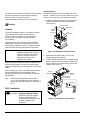
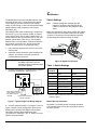
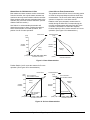
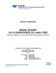
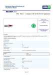
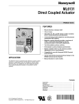
FANs 268.1, 1628.3, 977
Installation Bulletin
Issue Date
M100C
0600
M100C Series Actuator with Digital Control Signal Input
and R81CAA-2 Interface Board
I nstallation
Parts Included
Take the following precautions for the actuator:
•
proportional spring return or non-spring return
actuator (R81CAA-2 electronics installed)
•
•
five 1/4 in. female quick connect terminals
•
LVR27A-602 crank arm (only included with the
spring return models)
Do not install the actuator in atmospheres where
explosive vapors or gases could be present, or
environments where substances corrosive to the
device’s internal components could be present.
•
Seal wiring entering into return air systems to
prevent aspiration of corrosive air into the actuator.
R81CAA-2:
•
top cover electronics assembly
•
terminal board
•
two No. 6-32 x 5/16 in. Phillips-head screws
Tools Needed
•
No. 2 Phillips screwdriver
•
3/16 in. (5 mm) flat-blade screwdriver
•
punch and hammer
Precautions
IMPORTANT:
All M100C Series actuators are
intended to control equipment
under normal operating conditions.
Where failure or malfunction of
M100C actuators could lead to an
abnormal operating condition that
could cause personal injury or
damage to the equipment or other
property, other devices (limit or
safety controls) or systems (alarm
or supervisory) intended to warn of,
or protect against, failure or
malfunction of M100C actuators
must be incorporated into and
maintained as part of the control
system.
C ontrol Input
M100C Series actuators receive and interpret digital
commands from a controller for accurate positioning of
the output shaft. The M100CAA-2 is a dual direct and
reverse acting model replacing the M100CAA-1 (direct
acting only) and M100DAA-1 (reverse acting only)
models.
The actuator’s travel is factory set at 90° and is
field adjustable from 65 to 270°. The timing of the
actuator is 38 seconds for 90° rotation and 60 seconds
for 160° rotation.
D irection of Rotation
The actuators are factory set at the zero position and
for 90° travel. The zero position is 10° Clockwise (CW)
from vertical. (See Figure 2.) Spring return models
always return Counterclockwise (CCW) to the zero
position when power is removed.
Direction of Drive Rotation
Terminals CW and T1 Shorted
Keyway
10°
Zero
Position
Drive Shaft
Direction of Drive Rotation
Terminals CCW and
T1 Shorted
LOAD END
Figure 1: Direction of Rotation
© 2000 Johnson Controls, Inc.
Part No. 34-636-70, Rev. A
Code No. LIT-2681113
1
www.johnsoncontrols.com
Installing Boards
All reference to the direction of rotation is when viewing
the load end stamped on the actuator housing as
shown in Figure 1. From this view, the
Counterclockwise (CCW) limit is the zero position.
M ounting
M100X base actuators are not provided with circuit
boards. To install one, loosen the actuator’s two cover
screws, remove the cover, and proceed as follows:
1. Install the terminal board by carefully placing the
terminal receptacles onto the pin terminals.
(See Figure 2.)
Terminal Board
Receptacles
Actuator
Follow the installation steps for the linkage kit used to
couple the actuator and the controlled device.
When not utilizing a damper or valve linkage kit,
use four 1/4 x 1 in. bolts to mount the actuator
(not included).
Terminal
Board
Screws (2)
Pin
Terminals
Upright mounting of the actuator is recommended.
Multi-position mounting is acceptable as long as the
output shaft is parallel to the floor. Locate the actuator
where the shaft and wiring terminals are accessible.
IMPORTANT:
For installations using the
CVR83A-600R Weather Cover Kit,
mount the actuator in an upright
position to prevent water from
entering the enclosure and
damaging the actuator.
Make all linkage connections to the drive shaft on the
load end of the actuator, rated for up to 200 lb dead
weight. Limit the load on the auxiliary end to 10 lb dead
weight.
When mounting on a valve, mount the actuator above
the horizontal plane of the valve piping to avoid
damage to the actuator if the valve leaks or develops
condensation.
Note:
Valve medium temperatures above 250°F
(121°C) are acceptable only if the actuator’s
maximum ambient temperature is below 105°F
(41°C).
R81C Installation
!
2
CAUTION: Equipment Damage Hazard.
Disconnect all power supplies
before removing the wiring
connections and boards to avoid
possible damage to the
equipment.
Figure 2: Installing the Terminal Board
2. Fasten the board with the No. 6-32 x 0.312
Phillips-head screws supplied.
3. Install the ribbon attached cover-mounted vertical
board, carefully placing the terminal receptacles
onto the two sets of pin terminals so all pins are
aligned. (See Figure 3.)
Terminal
Receptacles
Attached
Cover
Vertical Board
Pin Terminals
Receptacles
Pin Terminals
Figure 3: Installing the Vertical Board
M100C Series Actuator with Digital Control Signal Input and R81CAA-2 Board Installation Bulletin
4. Place the bracket, supplied with the actuator, over
the vertical board and fasten it in place with the
captive screw. (See Figure 4.)
3. Pull the vertical board straight upward, being
careful not to bend or damage the pin terminals.
4. Remove the two screws from the terminal board.
5. Grasp the receptacles and remove the terminal
board by lifting upward, being careful not to bend
or damage the pin terminals.
Bracket
Captive
Screw
Vertical Board
W iring
!
Figure 4: Installing the Bracket
5. Apply the adhesive-backed identification label
provided to the actuator bracket. (See Figure 5.)
Bracket
M150 X GA-1
C
Identification Label
CAUTION: Equipment Damage Hazard.
Disconnect all power supplies
before wiring connections are
made. Check all wiring
connections before applying
power to the system.
Short-circuited or improperly
connected wires will result in
permanent damage to the
equipment.
Follow these procedures to wire the actuator:
•
Make all wiring connections using copper
conductors only. Wire in accordance with the
National Electrical Code and local regulations.
•
Use separate transformers on each M100 actuator
to avoid potential miswiring or control signal
problems.
•
Locate all splicing and excess wiring outside the
actuator wiring compartment. If desired, add a
standard electrical box to the actuator’s wiring
compartment. (See Figure 6.)
Note: The letter on the label completes the
model number of the M100 actuator
after R81 installation.
Figure 5: Installing the Identification Label
Wiring
Compartment
Removing Boards
To remove a circuit board, loosen the cover screws
and remove the actuator cover. (The old cover will be
replaced by the new furnished cover.)
1. Disconnect all wiring to the terminal board.
2. Loosen the captive screw, and remove the
bracket. (See Figure 4.)
Figure 6: Wiring Compartment
M100C Series Actuator with Digital Control Signal Input and R81CAA-2 Interface Board Installation Bulletin
3
C alibration
The M100C does not require shielded cable on runs
less than 50 feet (15 m). Avoid running low voltage
control wiring in the same conduit as line voltage
wiring, 24 VAC wiring, or other conductors that supply
highly inductive loads (contactors, coils, motors,
generators, etc.)
Use shielded cable if the control wiring is longer than
50 feet (15 m), run in a common conduit, or located
near inductive loads. Use 22 AWG, Beldfoil 8761, or
an equivalent for runs up to 250 feet (76 m). For runs
between 250 to 500 ft (76 to 152 m), use 18 AWG,
Beldfoil 8760, or an equivalent. Connect the shield to
the controller (Common) only. Do not connect the
shield to any other point. To connect the wiring:
Switch Settings
Note:
If switch settings are changed after the
actuator is powered, short the BUS to the
COM for a moment for the changes to take
effect.
Make field adjustments using the 8-position DIP switch
located on the cover-mounted circuit board as shown
in Figure 8. The position of these switches specifies
the operating parameters as shown in Table 1.
1 2 3 4 5 6 7 8
1. Use a hammer and punch to drive out one of the
access holes.
O
N
2. Install the conduit connector (not provided) to the
actuator, and secure it using the conduit nut
provided with the connector.
IMPORTANT:
Proper wiring polarity of the COM
and BUS connections must be
maintained when multiple actuators
are wired in parallel.
CW
CC
CCW BUS
Tape off the shield end
at the actuator. Connect
the shield only at the
controller.
Level 1 Bus or Zone Bus
from the Controller
Switch
Number
24 VAC
Power
Supply
Figure 7: Typical Single Unit Wiring Diagram
4. Connect isolated 24 VAC to Terminals T1 and T2.
Figure 7 shows a wiring configuration. Refer to the
M100C Series Actuator with Digital Control Signal
R81CAA-2 Interface Board Application Note
(LIT-2681132 in FAN 268.1, 977, or 1628.3) for more
specific wiring information.
4
ST
M
T1
2
Table 1: Switch Settings
T1
T2
BU
Figure 8: Digital Circuit Board
3. Connect the controller to COM and BUS located in
the wiring compartment. (See Figure 7.)
M100C
COM
CW
W
CO
*
On Function
Off Function
1
Slave
Master
2
S-curve
Linear
3
Reverse Acting
Direct Acting
4
Zone Bus
L1 Bus
5*
Address Selection
Address Selection
6*
Address Selection
Address Selection
7*
Address Selection
Address Selection
8*
Address Selection
Address Selection
Refer to Address Selection section for complete address
selection options.
Master/Slave for Zone Bus
Set Switch 1 to the Off position for master operation.
The Zone Bus does not use the On position, which is
the slave function.
M100C Series Actuator with Digital Control Signal Input and R81CAA-2 Board Installation Bulletin
Master/Slave for DSC1000 Level 1 Bus
Linear/S-Curve Flow Characteristics
Both master and slave actuators receive commands
from the controller, but only the master actuator has
continuous two way communication with the controller.
Slave actuators send response messages back to the
controller only if an error occurs at the slave. (See the
Address Selection section.)
The greatest amount of flow occurs in the early portion
of travel for valves and dampers with non-linear flow
characteristics. The S-curve switch setting allows the
actuator to respond in a non-linear manner.
Use Switch 1 to select whether the actuator will
respond as a master or slave. Position the switch to
Off to set the actuator for master operation, and
position it to On for slave operation.
Percent Flow
(CW)
100%
Relative to the input command, actuator travel is
smaller during the initial 20%, increases during the
mid 60%, and decreases during the final 20% of the
command. Use Switch 2 to select the response.
Position Switch 2 to On to set the actuator for S-curve
operation. (See Figure 9 for characteristics.)
Actuator Rotation
(CW)
100%
80%
80%
Actuator 60%
Rotation
Actuator 60%
Rotation
40%
40%
Direct
Acting
20%
Reverse
Acting
20%
0%
(CCW) 0% 20% 40% 60% 80% 100%
Controller Command
0%
(CCW) 0% 20% 40% 60% 80% 100%
Controller Command
Figure 9: Linear Characteristics
Position Switch 2 to On to set the actuator for S-curve
operation. (See Figure 10 for characteristics.)
(CW)
100%
Percent Flow
80% Command =
90% Actuator Rotation
80%
0%
(CCW) 0%
(CW)
100%
20% Command =
90% Actuator Rotation
80%
Direct
Acting
Actuator 60%
Rotation
40%
20%
Actuator Rotation
Actuator
Rotation
Reverse
Acting
60%
40%
20%
20% Command =
10% Actuator
Rotation
20% 40% 60% 80% 100%
Controller Command
0%
(CCW) 0%
80% Command =
10% Actuator
Rotation
20% 40% 60% 80%
Controller Command
100%
Figure 10: S-Curve Characteristics
M100C Series Actuator with Digital Control Signal Input and R81CAA-2 Interface Board Installation Bulletin
5
Direct/Reverse Acting
The M100C is factory set for DA. A 0 to 100%
command will cause the load end output shaft to rotate
fully CCW at 0% and fully CW at 100%. Switch 3 is set
to Off.
!
When set for RA, a 0 to 100% command will cause the
load end output shaft to rotate fully CCW at 100% and
fully CW at 0%. Change Switch 3 to On.
CAUTION: Equipment Damage Hazard.
The phone jack connector on the
terminal board is for single-point
connection of the HVAC PRO
configuration tool. Do not connect
any other device at the phone
jack. This could result in damage
to the equipment or wiring.
L1/Zone Bus
C500 Controllers use the L1 Bus. Application Specific
Controllers (ASC) use the Zone Bus. Set Switch 4 to
the Off position to allow the actuator to communicate
with a C500 and to On to communicate with an ASC.
Note:
Refer to M100C Series Actuator with
R81CAA-2 Interface Board for C500 Digital
Controllers Application Note (LIT-2681132 in
FAN 268.1, 977, or 1628.3).
O4
N
5 6
O4
N
5 6
Note:
Refer to M100C Series Actuator with
R81CAA-2 Interface Board for C500 Digital
Controllers Application Note (LIT-2681132 in
FAN 268.1, 977, or 1628.3).
Zone Bus Controller Address Selection
7 8
4
5 6
7 8
O4
N
5 6
7 8
O4
N
O
N
5 6
7 8
O4
4
Address 22
5 6 7 8
5 6
7 8
N
Address 27
Figure 11: Address Switch Settings
for the Zone Bus
Table 2: Switch Values for the Zone Bus
Switch Number
On Value
Off Value
5
0
—
6
0
4
7
0
2
8
0
1
Note:
Switch 5 must be On and an additional value of 20
added to the total of the switch settings for
selection of the Zone Bus.
For example: To select Zone Bus Address 25, set
Switches 6 and 8 to Off and Switches 5 and 7 to On
(25 = 0 + 4 + 0 + 1 from the switch settings and +20
because of Zone Bus selection). Select any Zone Bus
address between 20 and 27 using the switches.
The addresses used by the ASC are 20 through 27.
Make the address assignment during HVAC PRO™
configuration for analog outputs. (See Figure 11.)
Refer to the HVAC PRO User’s Manual (FAN 637.5
or 1637.5) for details.
6
7 8
Address 25
Address 24
5 6
Address 26
1. Set all units as the master with the same address
when used with an ASC.
2. Set one unit as the master, and the remaining
units as slaves with the same address when used
with a C500.
4
Address 21
Address 23
Address Selection
Configure multiple actuators with a separate address
when each one performs a different function. When all
the actuators perform the same function:
O
N
Address 20
O
N
The controlled device will respond only to a command
preceded by its assigned address code number. The
positioning of Switches 5, 6, 7, and 8 provides address
information to the controller. The switches are each
positioned so that the sum of their individual values
provides the desired address value.
7 8
M100C Series Actuator with Digital Control Signal Input and R81CAA-2 Board Installation Bulletin
Travel Adjustment
The rotation range of M100C is adjustable from
65 to 270°. The controller sends position commands to
the actuator ranging from 0 to 100%. The actuator
responds to these commands only over its selected
range of travel. (See Figure 12.)
100%
(CW)
Reverse
Acting
Note:
Manually driving the actuator will override the
controller's command. Be sure to disconnect
any control wiring before manually driving the
actuator.
1. Remove all control wires, and make sure the travel
adjustment potentiometer is set fully CCW.
Actuator
Rotation
2. Apply 24 VAC between T1 and T2.
3. Jumper Terminals COM and CW to drive the
actuator to the full CW position.
Direct
Acting
(CCW)
0%
0%
Use the following procedures to make the adjustments,
or refer to the appropriate valve or damper linkage
literature.
Controller Command
100%
Figure 12: Full Range Rotation
For example: If a DA actuator has its travel set at 120°,
a 50% command from the controller would position the
actuator at 60° of rotation. A 100% command would
position the actuator at 120° of rotation.
4. Slowly rotate the travel adjustment potentiometer
CW to increase rotation until the corresponding
valve or damper is in the desired position.
5. Move the jumper from Terminal CW to
Terminal CCW to allow the actuator to return to
the full CCW position.
6. Make sure the power is off, and connect the
control wires.
For RA actuators with a travel set at 120° rotation, the
50% command positions the actuator at 60° rotation,
and a command of 100% positions the actuator at 0° of
rotation.
The travel adjustment potentiometer mounted on the
terminal board enables positioning of the M100
actuator within the range of 65 and 270° rotation.
Changing the travel adjustment affects the CW rotation
limit. Turning the adjustment CW increases the total
travel, and turning it CCW reduces it.
M100C Series Actuator with Digital Control Signal Input and R81CAA-2 Interface Board Installation Bulletin
7
T roubleshooting
A dditional Information
After installation and wiring are complete, make
system settings and apply power. Cycle the actuator
using the controller after assembling the linkage and
actuator to the valve or damper.
See Table 3 for accessories, and contact the nearest
Johnson Controls representative. Refer to Table 4 for
product specifications.
8
M100C Series Actuator with Digital Control Signal Input and R81CAA-2 Board Installation Bulletin
Table 3: Accessories
Product
Code Number
Description
Y68AA-1
Transformer, 120/24 VAC, 40 VA, 60 Hz, Class 2
Y68DA-1
Transformer, 240/24 VAC, 40 VA, 60 Hz, Class 2
Y68HA-1
Transformer, 24/24 VAC, 40 VA, 60 Hz, Class 2
S91DJ-1
Auxiliary switch kit with one Single-Pole, Double-Throw (SPDT) switch
S91EJ-1
Auxiliary switch kit with two SPDT switches
S91PT-1
Auxiliary potentiometer kit, 1000 ohm, 1/3 watt
CVR83A-600R
Weather cover kit
Y20DAA-2
Mounts the actuator to the top of a duct or any flat surface. Contains the LVR27A-602, LVR27A-600,
ROD16-3, and SWL10A-603Y (2).
Y20DAB-2
Mounts the actuator to the side of a duct or wall. Contains all items in the Y20DAA-2 plus
one BKT22A-602.
Y20EBA-1
Valve linkage kit for mounting Honeywell® valves with 1/4-28 stem connection to M120 or
M130 actuators
Y20EBA-2
Valve linkage kit for mounting Honeywell valves with 1/4-28 stem connection to M150 actuators
Y20EBA-3
Valve linkage kit for mounting Barber-Colman® valves with 1/4-28 stem connection to M120 or
M130 actuators
Y20EBA-4
Valve linkage kit for mounting Barber-Colman valves with 1/4-28 stem connection to M150 actuators
Y20EBD-1
Linkage kit for M120 or M130 actuators and 1-1/4 in. (DN 32) valves, produces 75 lb (334 N) seating
force
Y20EBD-2
Linkage kit for M140 actuators and 1-1/4 in. (DN 32) valves, produces 150 lb (607 N) seating force
Y20EBD-3
Linkage kit for M150 actuators and 1-1/4 in. (DN 32) valves, produces 270 lb (1202 N) seating force
Y20EBD-5
Linkage kit for M110 actuators and 1-1/4 in. (DN 32) valves, produces 40 lb (178 N) seating force
Y20EBD-6
Linkage kit for M120 or M130 actuators and 1-1/4 in. (DN 32) valves, produces 100 lb (449 N) seating
force
Y20EBE-1
Coupling adaptor to convert valves with a 5/16 in. stem and a hold down nut for Johnson Controls
1/2 to 3 in. valves manufactured prior to March 1969.
Y20EBE-2
Stem adaptor and centerpiece collar to adapt VT Series valves with slotted stems. (Y20EBD-5 also
required.)
Y20EBE-3
Hold down nut for cast iron and VB Series 2-1/2 to 4 in. valves and yoke nut for Barber-Colman
1/2 to 2 in. valves
Y20EBE-4*
Stem connector for Barber-Colman 2-1/2 to 4 in. valves, 5 per package. (Use with Y20EBD-3 or -6.)
Y20EBE-11
Valve Linkage Adaptor Kit for VG7000 valves. (Y20EBD Series kit also required.)
VG7000-M110
Mounting Kit for M110 actuator and 1/2 through 2 in. (DN15 through DN50) valves
VG7000-M130
Mounting Kit for M130 actuator and 1/2 through 2 in. (DN15 through DN50) valves
VG7000-M140
Mounting Kit for M140 actuator and 1/2 through 2 in. (DN15 through DN50) valves
VG7000-M150
Mounting Kit for M150 actuator and 1/2 through 2 in. (DN15 through DN50) valves
Y20DFC-1
Damper linkage kit for mounting the actuator to CD-1300 dampers only (includes a universal mounting
bracket for inside or outside damper frame mounting)
M100C Series Actuator with Digital Control Signal Input and R81CAA-2 Interface Board Installation Bulletin
9
Table 4: Specifications
Product
M100C Series Actuator with Digital Control Signal Input R81CAA-2 Interface Board
Power Requirements
24 VAC, Class 2, (20 to 30 VAC) at 50/60 Hz; 25 VA spring return, 20 VA non-spring return
Input Signal
Digital from Johnson Controls application specific controllers or the DSC1000
Input Signal Adjustments
Direct Acting (DA) or Reverse Acting (RA), Master or Slave, L1 Bus or Zone Bus, Linear or
S-curve flow characteristics, Address Selection: 10 through 27
Factory Settings: DA, Master, Linear, L1 Bus, Address 27
Mechanical Connection
3/8 in. (9.5 mm) square shaft, both ends
Maximum dead weight on output shaft: 200 lb (91 kg), load end; 10 lb (4.5 kg), auxiliary end
Mechanical Output
M110
M120
M130
M140
M150
Running Torque:
25 lb∙in (2.8 N∙m) spring return
35 lb∙in (4.0 N∙m)
50 lb∙in (5.6 N∙m) spring return
75 lb∙in (8.5 N∙m)
150 lb∙in (17 N∙m)
Breakaway and Stall (minimum):
100 lb∙in (11 N∙m)
70 lb∙in (7.9 N∙m)
200 lb∙in (23 N∙m)
150 lb∙in (17 N∙m)
300 lb∙in (34 N∙m)
Rotation Range
Fixed zero, adjustable full travel 65 to 270°; factory set at 90° full travel
Rotation Timing
(at Rated Load)
60 seconds for 160° travel nominal, 60 Hz
38 seconds for 90° travel nominal, 60 Hz
75 seconds for 90° spring return
Cycle Life
M110 and M130 spring return models:
150,000 cycles at rated load
M120, M140 and M150 non-spring return models: 200,000 cycles at rated load
Electrical Connection
1/4 in. quick-connect spade terminals
Action
CW rotation on 0 to 100% command (DA) and CCW rotation on 0 to 100% command (RA);
factory set for DA
Ambient Operating
Conditions
Non-spring Return:
Spring Return:
Ambient Storage
Conditions
-40 to 140°F (-40 to 60°C), 90% RH
Enclosure
NEMA 2, IP32
Dimensions (H x W x D)
Spring Return:
Non-spring Return:
6.23 x 5.64 x 7.68 in. (158 x 143 x 195 mm)
6.23 x 5.64 x 4.94 in. (158 x 143 x 125 mm)
Shipping Weight
Spring Return:
9 lb (4.1 kg)
Agency Compliance
UL:
UL 916 Listed, File E107041, CCN PAZX
UL 873 Recognized, File E27734, CCN XAPX2
EU Directive Compliance
M100C:
-40 to 125°F (-40 to 52°C), 90% RH, 25% duty cycle
-35 to 125°F (-37 to 52°C), 90% RH, 25% duty cycle
Non-spring Return:
6.5 lb (2.9 kg)
CSA: M100C:
C22.2 No. 24 Certified, File LR948, Class 4813 02
M100X and R81:
No UL Listing or CSA Certification
89/336/EEC (CE Mark)
The performance specifications are nominal and conform to acceptable industry standards. For application at conditions beyond these
specifications, consult the local Johnson Controls office. Johnson Controls, Inc. shall not be liable for damages resulting from misapplication
or misuse of its products.
10
M100C Series Actuator with Digital Control Signal Input and R81CAA-2 Board Installation Bulletin
Notes
M100C Series Actuator with Digital Control Signal Input and R81CAA-2 Interface Board Installation Bulletin
11
Notes
Controls Group
507 E. Michigan Street
P.O. Box 423
Milwaukee, WI 53201
12
Printed in U.S.A.
www.johnsoncontrols.com
M100C Series Actuator with Digital Control Signal Input and R81CAA-2 Board Installation Bulletin