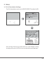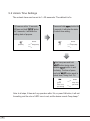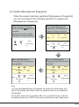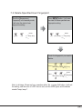
1
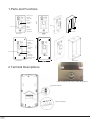
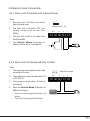
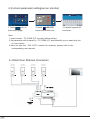
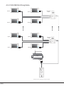
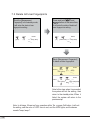
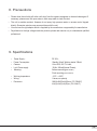
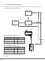
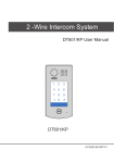
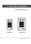
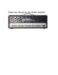
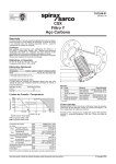
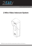
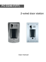
PC-D248-F(FF)
2-wired door station
User manual
1.Parts and Functions
Camera Lens
Speaker
Fingerprint
window
KEY 1
182 mm
Night Light
LED 1
30 mm
KEY 2
LED 2
Call Button
Microphone
Rainy Cover
DPC-D248-F
Camera Lens
Night Light
LED 1
Fingerprint
window
KEY 1
220 mm
Speaker
KEY 2
LED 2
Call Button
Microphone
Screws for panel
mounting
DPC-D248-FF
Side View
Mounting box
2.Terminal Descriptions
KEY1 and KEY2 work only for a while after power on
1 2 3
Lock Control Jumper
Main Connect Port
-1-
• Lock Control Jumper: To select the lock type.
•
•
•
•
•
Main Connect Port: To connect the bus line and the electronic locks.
BUS: Connect to the bus line, no polarity.
PL: External lock power input, connect to the power positive(power +).
S+: Lock power(+) output.
S-: Lock power(-) output, connect to the power(-) input of locks(only when using the door
station to power the locks, if using the external power supply for the locks, the S- will not be
connected).
3.Door Station Mounting
3.1 PC -D248-F Mounting
-2-
3.2 PC -D248-FF Mounting
4. System Wiring and Electric Lock Connection
4.1 Basic Connection
AC~
1 2 3
D IPS
-3-
ON
PC6
4.2 Electric Lock Connection
4.2.1 Door Lock Controlled with Internal Power
Note:
1.
Electronic lock of Power-on-to-unlock
type should be used.
2.
The door lock is limited to 12V, and
holding current must be less than
250mA.
3.
The door lock control is not timed from
Exit Button(EB).
4.
The Unlock Mode Parameter of
Monitor must be set to 0 (by default).
1 2 3
Jumper position in 2-3
BUS
PL
S+
S-
* EB
LOCK
4.2.2 Door Lock Controlled with Dry Contact
Note:
1.
The external power supply must be used
according to the lock.
2.
The inside relay contact is restricted to AC
or DC 24V/1A.
3.
The jumper must be taken off before
connecting.
4.
Setup the Unlock Mode of Monitor for
different lock types.
• Power-on-to-unlock type:Unlock Mode=0 (by
default)
• Power-off-to-unlock type:Unlock Mode=1
Take off the Jumper
BUS
PL
S+
S-
POWER
SUPPLY
LOCK
-4-
4.3 Unlock parameter setting(set on monitor)
ALLER SETUP
123
_
1.Touch
icon on
main menu page.
2.Touch
UNLOCK
button and hold for 2s.
3.A digital keypad will
be shown.
Note:
1. must connect PC -D248-(F)F correctly before setting.
2. the parameter will be saved in PC -D248-(F)F automatically,so you need only set
on one monitor.
3. Here we take the P M - D2 7 5 monitor for example, please refer to the
corresponding user manual.
4.4 Multi Door Stations Connection
-5-
4# Camera
3# Camera
2# Camera
1# Camera
(Device Address:3)
(Device Address:2)
(Device Address:1)
(Device Address:0)
4.5 Multi Monitors Connection
4.5.1 Basic IN-OUT Wiring Mode
Code=15
Code=14
Code=0
AC~
(Device Address:0)
NOTE:Here we take PM -D275 (the monitor) for example.
-6-
4.5.2 With DBC4A Wiring Mode
Code=12
Code=3
Code=2
A B C D
Impedance
switch
Code=1
Code=0
AC~
100~240VAC
PC6
BUS(IM) BUS(DS)
(Device Address:0)
NOTE:Here we take PM -D275(the monitor) for example.
-7-
OFF ON
DBC4A
Code=13
Impedance
switch
A B C D
Code=14
OFF ON
DBC4A
Code=15
5. Setup
5.1 ID of Doorstation Settings
The ID of doorstation can be set to ID0/ID1/ID2/ID3.The default is ID0.
Press and hold
and
button for 3 seconds at
the same time, it will enter the
state of setting.
1
Buzzer
beep+, beep
(off)
Followed by pressing the
button, each time you press
to replace the
Note:The will cycle between
ID0
ID1
ID2
ID3.
1
ID2: (green,flash 3 times)
Buzzer
beep one
beep twice
beep 3 times
beep 4 times
Note: In all steps, if there isn’t any operation within 10s, or press Call button, it will exit
the setting, and the color of LED1 turns to red, and the buzzer sounds "beep, beep+".
-8-
5.2 Unlock Time Settings
The unlock time can be set to 1~30 seconds. The default is 1s.
1)Power-on within 10 seconds;
2)Press and hold
button
for 3 seconds, it will enter the
setting state of prepare.
1
(red,flash)
Press and hold
button for
3 seconds, it will enter the state
of unlock time setting.
Buzzer
beep+,beep
1
Buzzer
beep+,beep
(off)
this time press and hold
button,timing starts;
release
button to end
the timing. The time of press
and hold
button equal to
unlock time.(Timing Unit: 1s)
1
(green,
fl ash once
per second
Buzzer
beep once
per second
Note: In all steps, if there isn’t any operation within 10s, or press Call button, it will exit
the setting, and the color of LED1 turns to red, and the buzzer sounds "beep, beep+".
-9-
5.3 Ringtone Mode Settings
The system supports three ringtone modes: [A]one ringtone, [B]
continuous ringtone, [C]forbid ringtone. The default is one ringtone.
1)Power-on within 10 seconds;
2)Press and hold
button
for 3 seconds, it will enter the
setting state of prepare.
1
(red,flash)
Press and hold
button for
3 seconds, it will enter the state
of ringtone mode setting.
Buzzer
beep+,beep
1
Buzzer
beep+, beep
(off)
Followed by pressing the
button,each time you press
to replace the ringtone mode;
Note:The ringtone mode will cycle
between
1
Buzzer
beep one
beep twice
beep 3 times
Note: In all steps, if there isn’t any operation within 10s, or press Call button, it will exit
the setting, and the color of LED1 turns to red, and the buzzer sounds "beep, beep+".
-10-
6. Register [Management Fingerprint]
[Management Fingerprint] will serve as a registered or delete
credential of user fingerprint. The system can only store a
management fingerprint.
6.1 Register [Management Fingerprint]
When the system has never been registered [Management
Fingerprint], you can according to the following operation to
register [Management Fingerprint].
1)Power-on within 10 seconds;
2)Press and hold
button for
3 seconds;
3)It will enter the state of registered
[Management Fingerprint] setting.
Touch finger in the fingerprint
window, get on the first time
identified;
1
Success:
2
green,
(off)
flash 3 times)
Buzzer
beep+,beep
(blue)
1
(off)
2
(off)
Buzzer
beep+,beep
1
Failure:
2
red,
(off)
flash 3 times)
Buzzer
beep,beep,beep
(off)
Note: 1)In the second identified,
when it succeeded, the system will
exit the setting, then return to the
standby state; When it failed, the
system will return to the operation
of first identified.
2)In all steps, if there isn’t any
operation within 10s, or press Call
button, it will exit the setting, and
the color of LED1 turns to red, and
the buzzer sounds "beep, beep+".
Touch finger in the fingerprint
window, get on the second time
identified.
1
Success:
green,
(on)
flash 3 times)
Failure:
red,
(off)
flash 3 times)
1
2
Buzzer
beep+
2
Buzzer
beep,beep,beep
(off)
-10-
6.2 Update [Management fingerprint]
When the system has been registered [Management Fingerprint],
you can according to the following operation to register new
[Management Fingerprint].
1)Power-on within 10 seconds;
2)Press and hold
button for
3 seconds;
3)It will enter the state of update
[Management Fingerprint] setting.
Touch original [Management
Fingerprint], make [Management
Fingerprint] change confirmed;
Success:
1
2
LED 1
LED 2
(off)
(off)
LED 1
LED 2
Buzzer
beep+,beep
Buzzer
beep+,beep
(off)
Failure: ( red,
(off)
flash 3 times)
Buzzer
beep,beep,beep
(red)
ouch new [Management
Fingerprint], get on the second
time identified.
1
Success:
2
green,
(on)
flash 3 times)
ouch new [Management
Fingerprint], get on the first time
identified.
1
Buzzer
beep+
Success:
2
green,
(off)
flash 3 times)
Buzzer
beep+,beep
(blue)
1
Failure:
red,
(off)
flash 3 times)
(off)
2
1
Buzzer
beep,beep,beep
Failure:
red,
(off)
flash 3 times)
2
Buzzer
beep,beep,beep
(off)
Note:
1)In the second identified,when it succeeded, the system will exit the setting, then
return to the standby state; When it failed, the system will return to the operation of
first identified.
2)In all steps, if there isn’t any operation within 10s, or press Call button, it will exit
the setting, and the color of LED1 turns to red, and the buzzer sounds "beep, beep+".
-12-
7. Register User Fingerprints
User fingerprints will serve as a unlock credential for user. The
system can store 200 user fingerprints.
7.1 Add User Fingerprints
onch the [Management
Fingerprint] In the standby mode;
It will enter the state of user
fingerprints setting.
1
2
(green)
Buzzer
beep+,beep
(off)
Touch new fingerprint you need,
get on the second time identified.
1
Success:
Press
button, It will enter
the state of add user fingerprints
setting.
2
1
(off)
1
Success:
2
Buzzer
green,
(flash
flash 3 times) slowly) beep+,beep
(blue)
1
2
1
Buzzer
red,
(flash
beep,beep,beep
flash 3 times) slowly)
(off)
beep+,beep
(flash slowly)
Buzzer
green,
(flash
flash 3 times) slowly) beep+
Buzzer
Touch new fingerprint you need,
get on the first time identified.
(off)
Failure:
2
Failure:
2
Buzzer
red,
(flash
beep,beep,beep
flash 3 times) slowly)
(off)
Note:
1)In the second identified, regardless of success or failure, the system will
return to the operation of first identified, you can continue to add new fingerprint;
2)In all steps, if there isn’t any operation within 10s, or press Call button, it will exit the
setting, and the color of LED1 turns to red, and the buzzer sounds "beep, beep+".
-13-
7.2 Delete Specified User Fingerprint
onch the [Management
Fingerprint] In the standby mode;
It will enter the state of user
fingerprints setting.
1
(green)
2
(off)
Press
button, It will enter
the state of delete specified user
fingerprints setting.
Buzzer
beep+,beep
1
(off)
2
Buzzer
beep+,beep
(flash quickly)
Touch the fingerprint you need to
delete.
1
Success:
2
Buzzer
green,
(flash
flash 3 times) quickly beep+,beep
(off)
1
Failure:
2
Buzzer
red,
(flash beep,beep,beep
flash 3 times) quickly
(off)
Note: In all steps, if there isn’t any operation within 10s, or press Call button, it will exit
the setting, and the color of LED1 turns to red, and the LED2 lights, and the buzzer
sounds "beep, beep+".
-14-
7.3 Delete All User Fingerprints
onch the [Management
Fingerprint] In the standby mode;
It will enter the state of user
fingerprints setting.
1
(green)
2
(off)
Press and hold
and
button at the same time,
It will enter the state of delete all
user fingerprints setting.
Buzzer
beep+,beep
1
(off)
2
Buzzer
beep+,beep
(double flash)
onch [Management Fingerprint]
to delete all user fingerprints.
1
Success:
1
Failure:
2
green,
on
flash 3 times)
red,
Buzzer
beep+
2
Buzzer
double
flash 3 times) flash beep+,beep,beep
(off)
Note:In this step, when it succeeded,
the system will exit the setting, then
return to the standby state; When it
failed, the system will return to the
previous step.
Note: In all steps, if there isn’t any operation within 10s, or press Call button, it will exit
the setting, and the color of LED1 turns to red, and the LED2 lights, and the buzzer
sounds "beep, beep+".
-15-
8. Precaustions
• Please clean the unit with soft cotton cloth, don't use the organic impregnant or chemical clean agent. If
necessary, please use a little pure water or dilute soap water to clean the dust.
• The unit is weather resistant. However do not spray high pressure water on access control keypad
directly. Excessive moisture may cause problems with the unit.
• You must use the right adaptor which is supplied by the manufacture or approved by the manufacture.
• Pay attention to the high voltage inside the products, please refer service only to a trained and qualified
professional.
9. Specifications
•
•
•
•
•
Power Supply :
Power Consumption:
Camera:
Lock Power supply:
Mounting:
• Working temperature:
• Wiring:
• Dimension:
DC 24V ;
Standby 34mA; Working status 158mA;
Color ARS; 500 TV Lines;
12Vdc, 280mA(Internal Power);
Surface mounting(DPC-D248-F)
Flush mounting (DPC-D248-FF)
-15ºC ~ +55ºC
2 wires,non-polarity
182(H)×93(W)×44(D)mm (PC -D248-F)
220(H)×120(W)×50(D)mm (PC -D248-FF)
-16-
10. Cables Requirements
The maximum distance of the wiring is limited in the 2-wired system. Using different cables may also affect
the maximum distance which the system can reach.
The farest monitor
monitor
with two or four monitors
monitor
monitor
DBC4A
B
C
AC~
100~240VAC
PC6
When Monitor quantity < 20
Cable Usage
2
Twisted cable 2x0.75 mm
2
Twisted cable 2x1 mm
BUS(IM) BUS(DS)
A
B
C
60
60
30
80
80
40
When Monitor quantity > 20
Cable Usage
2
Twisted cable 2x1 mm
2
Twisted cable 2x1.5 mm
A
B
C
70
30
20
70
50
30
Note:If the monitor has been specified the distance,refer to
the parameter
-17-