1
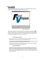
FASTCAMERA SERIES FAST VIEWER USER’S MANUAL COPYRIGHT NOTICE Copyright 2003 by FastVision, LLC. All rights reserved. This document, in whole or in part, may not be copied, photocopied, reproduced, translated, or reduced to any other electronic medium or machine-readable form without the express written consent of FastVision, LLC. FastVision makes no warranty for the use of its products, assumes no responsibility for any error, which may appear in this document, and makes no commitment to update the information contained herein. FastVision, LLC. retains the right to make changes to this manual at any time without notice. Document Name: Fast Motion User’s Manual Document Number: xxxxxxxxx Revision History: 1.0 Dec 25, 2002 Trademarks: FastVision is a registered trademark of FastVision, LLC. AltiVec is a trademark of Motorola Inc. Channel Link is a trademark of National Semiconductor CodeWarrior is a registered trademark of Metrowerks Corp. FastChannel is a registered trademark of Alacron, Inc.. FastSeries is a registered trademark of Alacron, inc.. Fast4, FastFrame 1300, FastImage, and FastI/Oare registered trademarks of Alacron, Inc.. FireWire is a registered trademark of Apple Computer Inc. 3M is a trademark of 3M Company MS DOS is a registered trademark of Microsoft Corporation SelectRAM is a trademark of Xilinx Inc. Solaris is a trademark of Sun Microsystems Inc. TriMedia is a trademark of Philips Electronics North America Corp. Unix is a registered trademark of Sun Microsystems Inc. Virtex is a trademark of Xilinx Inc. Windows, Windows 95, Windows 98, Windows 2000, Windows NT, and Windows XP are trademarks of Microsoft All trademarks are the property of their respective holders. FastVision, LLC. 131 Daniel Webster Highway, #529 Nashua, NH 03060 USA Telephone: 603-891-2750 Fax: 603-891-1881 Web Site: http://www.fast-vision.com/ Email: [email protected], or [email protected] TABLE OF CONTENTS Copyright Notice ………………………………………………………………………………….. Table of Contents ………………………………………………………………………………… Manual Figures & Tables ………………………………………………………………..………. I. ii iii iii INTRODUCTION.................................................................................................................... 5 A. Installation ..................................................................................................................... 5 B. Introduction ................................................................................................................... 5 II. USER’S GUIDE .................................................................................................................. 6 A. Camera Settings............................................................................................................ 6 B. 1. 2. 3. Recording Options........................................................................................................ 6 Grab button ..................................................................................................................... 6 Grab To HD button.......................................................................................................... 6 Stop Grab button............................................................................................................. 7 C. 1. 2. Triggered Grabbing....................................................................................................... 7 Trigger Settings............................................................................................................... 8 Fire Trigger button........................................................................................................... 9 D. 1. 2. Video/Frame Manager................................................................................................. 10 Play back buttons.......................................................................................................... 10 Recording Schedule...................................................................................................... 11 E. 1. 2. Relations Between Record Sequence Table and Grabbing Mode......................... 12 Continuous Grabbing .................................................................................................... 12 Triggered Grabbing ....................................................................................................... 12 1. 2. Fast Viewer...................................................................................................................... 13 Zoom and panning options ........................................................................................... 13 Play back buttons.......................................................................................................... 13 III. IV. TROUBLESHOOTING ..................................................................................................... 14 V. FASTVISION TECHNICAL SUPPORT............................................................................ 15 A. Contacting Technical Support................................................................................... 15 B. Returning Products for Repair or Replacements .................................................... 15 C. Reporting Bugs ........................................................................................................... 17 LIST OF FIGURES Figure 1: Select Camera dialog box ...............................................................................................6 Figure 2: Trigger setup dialog box..................................................................................................8 Figure 3: Video/Frame Manager controls.....................................................................................10 Figure 4: Recording schedule .....................................................................................................11 Figure 5: Fast Viewer ...................................................................................................................13 I. INTRODUCTION A. Installation Follow these instructions to install the FastViewer software: 1. Insert the FastViewer installation CD-ROM into your CD-ROM drive. 2. Access your CD-ROM drive, go to ”\Setup” directory and double click “fastViewer2-win2k-obj-x.y.z.exe” to run the FastViewer installation. 3. Follow the “InstallShield Wizard” on screen instructions. 4. After the installation is complete, reboot the PC System to complete the software installation and the environment setup. B. Introduction FastViewer is a digital recording system that is based on the Alacron’s FastSeries1300 family of frame grabbers. The application works under Windows 2000/NT operating systems. The FastViewer system enables recording of video from a variety of digital and analog sources. FastViewer enables recording of high frame rate images into system memory (RAM) and/or disk files. The maximum recording rate to the system memory is 90 MB/s. The Frame rate to the disk files depends on the hardware configuration. FastViewer software includes the FastViewer, that allows offline browsing of directories that contain images saved in TIFF format as recorded by the FastViewer system. II. USER’S GUIDE A. Camera Settings After initiating the FastViewer application, the first step to start using the FastViewer software, is to select the camera type by opening the “Select Camera” Dialog (Figure 1). This dialog enables to select the camera type, camera frame size and rate and the shutter speed. Additional attributes of camera parameters (if any) are displayed at the bottom of the dialog. After selecting the camera type, the camera details appear in the camera setting frame at the main application window. Figure 1: Select Camera dialog box B. Recording Options 1. Grab button Pressing the Grab button starts a continuous grabbing operation. Video frames captured from the camera are stored in the system memory in a circular buffer. During grabbing, the image area at the main application window is continuously updated with the latest video image from the camera at a refresh rate that depends on camera characteristics and system configuration. Zooming and panning functions are available by using the mouse. The grabbing operation continues until the user presses the Stop Grab button or until a trigger signal is received - according to trigger definition (see Triggered Grabbing par.). 2. Grab To HD button Pressing the Grab To HD button opens up a standard save file dialog. The user should choose a folder and provide a filename – under which all captured frames will be saved. . Immediately after confirming the filename, the system will begin saving the grabbed images to the selected directory as RAW data. If a recording schedule is defined the data is saved according to that schedule.(See Para. D.2 below). There are 3 options to stop the grabbing process: • Grabbing terminates per definitions in the recording schedule. • If a recording schedule is not defined, the system stops the grabbing after saving 1000 images. • Manual termination by pressing the Stop Grab button. At the end of the grabbing process, the images that were previously stored as RAW data, are converted to a TIFF format. A progress bar that appears at that time enables viewing the progress of saving and converting. The maximum conversion rate is dependent on image size and system configuration (Hard drive type, controller, RAM size, etc.). Using relatively large system RAM allows achieving burst writing at high frame rates. During garbing to the system hard disk, the image area at the main window is updated at a lower refresh rate - to prevent disturbance to system performance. 3. Stop Grab button After any one of the Grab commands was selected, the Stop Grab button stops the acquisition process of the images and storing of images to the buffer. When the Grab to HD command is selected the Stop Grab button stops the grabbing process manually. The saved RAW data images are converted to a TIFF image format. Zooming and panning features are available. C. Triggered Grabbing FastViewer provides a Trigger feature that enables capturing and viewing of images that occurred before and after a “trigger” signal was initiated. The amount of images to be captured prior to “Trigger” is defined by the Trigger % - see Figure 2: Trigger setup dialog box. The FastViewer trigger function in a “Stop On Trigger” function, i.e. the system has to be in a “Grab” mode before receipt of the trigger signal. The trigger signal can be either software driven - using the Fire Trigger button, or hardwaredriven - using one of the trigger input lines in the frame grabber connector. When a trigger signal is received, the current frame in the frames buffer is marked as a reference ID frame 0. All the frames accumulated prior to “Trigger” will be marked with a negative ID frame numberrelative to their position to the trigger, and all frames accumulated past the “trigger” – will be bear a positive ID number. The trigger percent – to be defined by user - determines the size of the frames buffer to be allocated to the pre–trigger images. The recordings process ends when the buffer filled up or when the user activated the Stop Grab button. After recording, the images are stored in the system RAM and may be viewed by using the preview buttons, or they may be saved by pressing the Save TIFF button. Note: The images are not saved automatically to the hard disk. Table 1 summarizes the system behavior at different trigger percentage options : Table 1: Trigger definitions Trigger Percent Buffer State 0% Full 0% Partial 100% Full 100% Partial Betwee n 0% to 100% Betwee n 0% to 100% Full Partial Process Continue to record one full-length buffer after receiving the trigger. If the user stops the recording, the frames that were recorded until then are available. Continue to record one full buffer. If the user stops the recording the frames that were recorded are available. The recording stops immediately and a full buffer is available- with all “historic” frames that were grabbed prior to “trigger”. The recording stops and the frames that were recorded are available. Continue recording until the post-trigger value is achieved and return a full buffer. If the user stops the recording a full buffer is returned Continue recording until the post-trigger value is achieved and return a full buffer, which includes the post-trigger frames and the pre-trigger frames. When the user stops the recording The pretrigger frames and the post-trigger frames that were recorded are returned. Note: The size of the buffer depends on the amount of system RAM reserved for the FastViewer system. 1. Trigger Settings Pressing the Trigger Setup button opens the trigger setup dialog as shown in Figure 2 Figure 2: Trigger setup dialog box Trigger Setup enables to define the trigger percentage value and trigger mode. The default trigger percentage is 0%, which means that the system will perform full buffer recording after receiving a trigger command. Trigger percentages are between 0% to 100% in 1% increments . A progress bar –located bellow the trigger percentage indicates the % value graphically. The default trigger mode is manual, which means that the user fires the trigger. The external trigger mode inhibits the software trigger operation and passes the trigger control to the frame grabber. The trigger set up and mode are part of the trigger settings frame at the main application window. 2. Fire Trigger button Pressing this button fires the software trigger to control the triggered grabbing operation as described above. D. Video/Frame Manager FastViewer provides Video/Frame controls to enable the user to view the images that were stored in the system memory and to save them as a collection of TIFF files or as an AVI movie file. The user can also determines the frame rate and “zoom in” and “zoom out” scale. Figure 3 and Table 2 present all the Video/Frame Manager controls Figure 3: Video/Frame Manager controls 1. Play back buttons Table 2: Play back buttons Play the recorded images from the current frame to the end of the recorded buffer according to the frame rate. Play the recorded images from the current frame to the beginning of the recorded buffer according to the frame rate. Pauses the images play process Moves to the beginning of the buffer and displays the first image in the recorded buffer. Moves to the end of the buffer and displays the last image in the recorded buffer. Moves forward through the recorded buffer manually frame by frame. Moves backwards through the recorded buffer manually frame by frame. 2. Recording Schedule Pressing the Open Record Table button opens up the recording schedule table, shown in Figure 4,which enables the definition of frames that have to be captured and allows skipping unwanted frames. The recording table can be fragmented to many recording strips to allow flexibility of capture. While working in ‘Triggered Grabbing’ mode, the frames are stored in the system RAM memory, and the recording table determines the frames that should be saved to hard disk when the Save TIFF button is activated. While working in ‘continuous grabbing to HD’ (activating the Grab to HD button), the recording table determines the frames that should be saved to the hard disk. Using the recording table in this mode allow the user to save long video frames sequence limited only by the amount of free hard disk space. Figure 4: Recording schedule To add a new entry to the table the user has to define the desired “From frame number”, the “To frame number” and the frame skip “Gap” - in the new frames parameters and press the “Add” button. In case of a conflict between the new parameters and the table, an error message will appear. In order to delete an entry in the table the user has to select that line in the table and press the “Delete” button. The record table data can be saved to a file by pressing the “save” button, and can be loaded from a file by pressing the “Load” button and selecting a desired file. E. Relations Between Record Sequence Table and Grabbing Mode 1. Continuous Grabbing When the record table is defined the grabbing and saving to hard disk process will be performed according to that table. If the table is empty, it will be considered as a one-line table starting from frame number 1 to frame number 1000 recording every frame. 2. Triggered Grabbing (see Figure 3) • Save TIFF button – After the trigger operation is terminated, the raw data located in the system RAM can be stored to the hard disk. The save option follows the recording schedule- if defined, . Otherwise, the whole content of the frame buffer will be saved. • Save AVI button - In Triggered Grabbing mode, after the trigger stops the user can save the raw data to the disk in an AVI movie format. This save option does not work according to the recording schedule even if it is defined. III. FAST VIEWER The FastViewer (Fig 5)allows viewing a sequence of video frames that were previously grabbed and saved to hard disk using the FastViewer system. Figure 5: Fast Viewer The first step in viewing is to load an image file from the disk files by pressing the “Browse Directories” button. The viewer displays the first image in the directory that can contain up to 10000 images. Attributes of the camera settings and the image description are presented at the bottom of the viewer for each image. 1. Zoom and pan options Zoom in button - Every click on that button will enlarge the image size by a factor of 2 in both dimensions. The mouse wheel can also operate the zoom. Zoom out button - Every click on that button will scale the image size down by a factor of 2. Moving the mouse wheel backward also operates the zoom. Panning is available when the image is greater then the viewer window. Dragging the image with the mouse left button activates panning. 2. Play back buttons The play back buttons enable to display forward and backwards all the images in the directory according to the defined frame rate (msec/frame). Displaying of the images begins at the current image that appears in the viewer. The track bar represents the current image position. Dragging the arrow in the track bar enables browsing manually through the images. 13 IV. TROUBLESHOOTING There are several things you can try before you call FastVision Technical Support for help. _____ Make sure the computer is plugged in. Make sure the power source is on. _____ Go back over the hardware installation to make sure that the system is properly installed. _____ Go back over the software installation to make sure you have installed all necessary software. _____ Run the Installation User Test to verify correct installation of both hardware and software. _____ Run the user-diagnostics test for your main board to make sure it’s working properly. _____ Insert the FastVision CD-ROM and check the various Release Notes to see if there is any information relevant to the problem you are experiencing. The release notes are available in the directory: \usr\fastvision\alinfo 14 V. FASTVISION TECHNICAL SUPPORT FastVision offers technical support to any licensed user during the normal business hours of 9 a.m. to 5 p.m. EST. We offer assistance on all aspects of processor board and PMC installation and operation. A. Contacting Technical Support To speak with a Technical Support Representative on the telephone, call the number below and ask for Technical Support: Telephone: 603-891-4317 If you would rather FAX a written description of the problem, make sure you address the FAX to Technical Support and send it to: Fax: 603-891-1881 You can email a description of the problem to [email protected] B. Returning Products for Repair or Replacements Our first concern is that you be pleased with your FastVision products. If, after trying everything you can do yourself, and after contacting FastVision Technical Support, you feel your hardware or software is not functioning properly, you can return the product to FastVision for service or replacement. Service or replacement may be covered by your warranty, depending upon your warranty. The first step is to call FastVision and request a “Return Materials Authorization” (RMA) number. This is the number assigned both to your returning product and to all records of your communications with Technical Support. When an FastVision technician receives your returned hardware or software he will match its RMA number to the on-file information you have given us, so he can solve the problem you’ve cited. When calling for an RMA number, please have the following information ready: _____ Serial numbers and descriptions of product(s) being shipped back _____ A listing including revision numbers for all software, libraries, applications, daughter cards, etc. _____ A clear and detailed description of the problem and when it occurs _____ Exact code that will cause the failure _____ A description of any environmental condition that can cause the problem 15 All of this information will be logged into the RMA report so it’s there for the technician when your product arrives at FastVision.Put boards inside their anti-static protective bags. Then pack the product(s) securely in the original shipping materials, if possible, and ship to: FastVision, LLC. 131 Daniel Webster Highway, #529 Nashua, NH 03060 USA Clearly mark the outside of your package: Attention RMA #XXX Remember to include your return address and the name and number of the person who should be contacted if we have questions. 16 C. Reporting Bugs We at FastVision are continually improving our products to ensure the success of your projects. In addition to ongoing improvements, every FastVision product is put through extensive and varied testing. Even so, occasionally situations can come up in the fields that were not encountered during our testing at FastVision. If you encounter a software or hardware problem or anomaly, please contact us immediately for assistance. If a fix is not available right away, often we can devise a work-around that allows you to move forward with your project while we continue to work on the problem you’ve encountered. It is important that we are able to reproduce your error in an isolated test case. You can help if you create a stand-alone code module that is isolated from your application and yet clearly demonstrates the anomaly or flaw. Describe the error that occurs with the particular code module and email the file to us at: [email protected] We will compile and run the module to track down the anomaly you’ve found. If you do not have Internet access, or if it is inconvenient for you to get to access, copy the code to a disk, describe the error, and mail the disk to Technical Support at the FastVision address below. If the code is small enough, you can also: FAX the code module to us at 603-891-1881 If you are faxing the code, write everything large and legibly and remember to include your description of the error. When you are describing a software problem, include revision numbers of all associated software. For documentation errors, photocopy the passages in question, mark on the page the number and title of the manual, and either FAX or mail the photocopy to FastVision. Remember to include the name and telephone number of the person we should contact if we have questions. FastVision, LLC. 71 Spit Brook Road, Suite 200 Nashua, NH 03060 USA Telephone: 603-891-4317 FAX: 603-891-1881 Web site: http://www.fast-vision.com/ Electronic Mail: [email protected] [email protected] 17