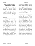
1
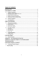
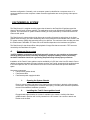
FASTCAMERA SERIES FAST-XL FASTVIEWER USER’S MANUAL FVM-00396 i COPYRIGHT NOTICE Copyright 2004 by FastVision LLC. All rights reserved. This document, in whole or in part, may not be copied, photocopied, reproduced, translated, or reduced to any other electronic medium or machine-readable form without the express written consent of FastVision LLC. FastVision makes no warranty for the use of its products, assumes no responsibility for any error, which may appear in this document, and makes no commitment to update the information contained herein. FastVision LLC. retains the right to make changes to this manual at any time without notice. Document Name: FastViewer-XL User’s Manual Document Number: FVM-00396. Revision History: 1.0 Aug. 19, 2004 2.0 Sept. 21, 2004 Trademarks: FastVision is a registered trademark of FastVision LLC. Channel Link is a trademark of National Semiconductor 3M is a trademark of 3M Company Windows, Windows 95, Windows 98, Windows 2000, Windows NT, and Windows XP are trademarks of Microsoft All trademarks are the property of their respective holders. FastVision LLC. 131 Daniel Webster Hwy #529 Nashua, NH 03060 USA Telephone: 603-891-4317 Fax: 603-891-1881 Web Site: http://www.Fast-Vision.com/ Email: [email protected], or [email protected] ii TABLE OF CONTENTS INTRODUCTION............................................................................................................. 4 FASTVIEWER-XL SYSTEM ........................................................................................... 5 A. 1. 2. 3. 4. 5. 6. Hardware Installation.....................................................................................................5 Opening the System Chassis ......................................................................................................... 5 Installing the Fast-XL frame grabber board................................................................................... 5 Closing the System Chassis........................................................................................................... 6 Attaching CLs to the frame grabber ............................................................................................... 6 Attaching CL cables to the FastCamera......................................................................................... 6 Connecting the FastCamera power supply .................................................................................... 7 B. Software Installation......................................................................................................7 C. Operating Modes............................................................................................................7 VIDEO CAPTURE MODE ............................................................................................... 9 D. 1. 2. 3. 4. E. 1. 2. 3. 4. F. Using Camera Controls .................................................................................................9 Frame Rate and ROI Selection .................................................................................................... 10 Exposure Control.......................................................................................................................... 11 Capturing Color Video .................................................................................................................. 12 Image sensor calibration .............................................................................................................. 13 Recording Controls .....................................................................................................14 Grab button................................................................................................................................... 14 Stop Grab button .......................................................................................................................... 14 Save Files button .......................................................................................................................... 15 Record Table ................................................................................................................................ 15 Triggered Grabbing .....................................................................................................16 1. 2. Trigger Settings ............................................................................................................................ 18 Fire Trigger button ........................................................................................................................ 18 PLAY BACK MODE...................................................................................................... 20 G. Play back buttons ........................................................................................................20 APPENDIX A. CAPTURE DESCRIPTION FILE .......................................................... 22 APPENDIX B. CHANGING FORMAT OF CAPTURED IMAGES................................. 23 TROUBLESHOOTING.................................................................................................. 26 FASTVISION TECHNICAL SUPPORT......................................................................... 26 H. I. Contacting Technical Support....................................................................................26 Reporting Bugs ...............................................................................................................28 iii INTRODUCTION This manual covers the FastVision FASTVIEWER-XL system and software. The FastViewer-XL system consists of a FastCamera connected by two custom Camera LinkL cables to the Fast-XL frame grabbers, see below, working in parallel to support the camera at the highest video rate. The FastViewer-XL application is a Windows GUI based application making the frame grabbers and camera work together for easy configuration and acquisition. The simplified board diagram is presented below. Proper operation of the FastViewer-XL relies on carefully selected hardware components integrated in a well balanced computer system. Achieving the digital video rate heavily depends on the underlying iv hardware configuration. Generally, such a computer system is classified as a computer server. It is recommended that no other computer or data movement applications are running during video capture operations. FASTVIEWER-XL SYSTEM The FastViewer-XL is a digital recording system that is based on the FastVision FastCamera and the Alacron Fast-XL family of frame grabbers. The application works under Windows XP/2000/NT operating systems. The FastViewer-XL system enables recording of video presented by a FastCamera at the full Camera LinkL speed. The FastViewer-XL system achieves high frame rate recording of images by storing them in the frame grabber internal memory first, than assembling video record collection into a seamless video record in the PC system memory (RAM) and (optionally) storing it in disk files. The maximum video recording rate from the FastCamera is 660 MB/s. The frame rate to the disk files depends on the hardware configuration. The FastViewer-XL also allows offline video playback of image files that were saved in TIFF format as recorded by the FastViewer-XL system. A. HARDWARE INSTALLATION **NOTE: Hardware components of the FastCamera-XL system are very sensitive to electrostatic discharge (ESD) and can be irreversibly damaged by improper handling. Persons performing hardware installation should use a grounding strip and strictly follow proper procedures. Installation of the Fast-XL frame grabber requires availability of a PCI slot in the Host PC chassis. Due to additional clearance needed by the board memory modules, the Fast-XL board should be positioned next to an unoccupied PCI slot or in the farthermost PCI slot on the motherboard that provides additional space. Necessary components: • Fast-XL frame grabber board, • FastCamera cable, • FastCamera power supply and cable 1. Opening the System Chassis Remove screws holding side pane of the chassis closest to the fans in the back, slide the panel out and put it away protecting from scratches and warping. The side panel should be replaced at the end of the hardware installation procedure. 2. Installing the Fast-XL frame grabber board Engage board support bracket in a holder if available in the chassis. Carefully slide frame grabber board in position until it is fully inserted in the PCI socket. Use a screw to attach rear bracket to the chassis. 5 Figure 1. Installing the Fast-XL frame grabber board in a chassis 3. Closing the System Chassis Reverse steps taken to open chassis restoring and affixing the side panel. 4. Attaching CLs to the frame grabber Take two standard Camera LinkL cables and attach one end of each cable to both CL connectors on the Fast-XL frame grabber board. Both connector screws should be evenly tightened for a reliable signal connection. (See Figure 2 below) 5. Attaching CL cables to the FastCamera Carefully attach CL cables from the frame grabber to the FastCamera following the picture in the Figure 2 below. 6 to J1 to J2 J2 J1 Power Figure 2. Connecting FastCamera to the Fast-XL frame grabber board 6. Connecting the FastCamera power supply Connect the round connector from the FastCamera power supply to the corresponding connector on the camera. Plug power cord from the AC outlet into receptacle on the FastCamera power supply. (See Figure 2 above) B. SOFTWARE INSTALLATION Follow these instructions to install the FastViewer-XL software: • Insert the FastViewer-XL installation CD-ROM into your CD-ROM drive. • Access your CD-ROM drive, by going to ”\Fast-XL” directory and double clicking Setup.exe to run the FastViewer-XL installation. • Follow the FastViewer-XL on screen instructions. • After the installation is complete, reboot the PC System to complete the software installation and the environment setup. Install the driver for the frame grabber board after reboot. The Plug-and-play dialog box will ask for the driver, point browser to C:\FastVision\FastViewer-XL\Drivers\win2k. Answer “Yes’” to allow installation for “PIXCI CL3SD PCI card” driver from that location. Reboot your PC system to load the driver. You can check successful installation by verifying that Settings->Control Panel->System->Hardware>Device Manager->Imaging devices->PIXCI CL3SD operates correctly and doesn’t have a yellow question mark attached to its name in the list. C. OPERATING MODES 7 The FastViewer-XL system operates in one of two self-descriptive distinct modes: Video Capture or Video Playback and Review. No special reconfiguration is required to transition between these operating modes and the operator can switch modes at will. Immediately after starting the FastViewer-XL application the users will see a large main screen that can be positioned anywhere in the system window. The screen displays video camera parameters and contains the most often used controls for both operating modes. The first step immediately after the FastViewer-XL application starts is to initialize the FastCamera by pressing the Camera Control button and set the appropriate frame rate and exposure. The application retains this information from session to session. If you see the right parameters in the Camera Control screen simply click OK and return back to the main screen. Figure 3. FastViewer-XL Main Screen Diagrams in Fig. 4 and Fig.13 below represent the sequence of controls in both operating modes. 8 Video Capture Sequence Start Program Camera Control Trigger Settings Grab Stop Grab Fire Trigger Record Table Save Files Figure 4. Sequence of controls in the Video Capture Mode VIDEO CAPTURE MODE D. USING CAMERA CONTROLS 9 The first step to start capturing video with the FastViewer-XL software is to initialize the FastCamera by pressing the Camera Control button. That action opens a new window displaying the camera setting in great detail and allowing the user to change the frame rate, frame exposure setting, position and size of the frame area that will be actually captured called Region-of-Interest or ROI. Figure 5. Camera Control screen 1. Frame Rate and ROI Selection There is a strong relationship between the size of the capture area on each frame and the video frame rate that can be captured by the camera and transferred to the frame grabbers defined by the Camera Link interconnect bandwidth. The user is free to change either frame rate or ROI depending on the purpose of the video capture application. The frame rate change is the easiest. It can be accomplished by either moving the slider under the Frame-Rate display box, or directly typing a value in the box. After approximately two seconds delay the application will accept new values and the typed value will be replaced by a more verbose message describing the new frame rate. Simultaneously, the box above frame rate display will show the video capture data rate generated by the frame rate necessary to transport video data to the Host PC. If displayed data rate exceeds capability of a chosen interconnect (Camera Link Basic, Medium, Full, or USB), video capture at such frame rate must be stored in the FastCamera internal memory and later forwarded to the Host PC at the slower rate. The FastViewer-XL application helps the user balance the effects of the changes. The FastViewer-XL adjusts size (but not position) of the ROI if the desired frame rate was changed beyond the capacity of the interconnect rate. On the other side, if the user makes the ROI a bit too large, the software reduces the frame rate. Once the selection is made, the software preserves it during and between sessions. The last set of user’s choices will be loaded and displayed the next time the FastViewer-XL is started. 10 The current ROI selection is indicated by a blinking green frame that can be dragged and repositioned by the user over the desired location in the frame. Actual values of ROI parameters will be displayed in the ROI parameter boxes. User can change them directly and activate new values by clicking on the Set button. The Full Frame button restores ROI parameters to the full resolution of the camera sensor. When it is necessary for the ROI of capture to be smaller then the full frame, it can be interactively positioned over the desired area in the frame justifying its name and region-of-interest. That operation can be done by directly specifying the position of the upper-left-corner of the ROI. It is done by editing values in the boxes called Top and Left or dragging the thin wire frame that appears in the center of the image preview panel when the ROI is less then the full frame. 2. Exposure Control Exposure control complements the function of mechanical lens aperture controls to match sensitivity of the camera CMOS image sensor to available lighting and get the best deal out of limited number of bit per pixel. Difference in signals from dark and bright regions of captured images should be spread as far as possible over sensor’s digitization range to extract most video information from the sensor. Figure 6. Histogram of Image captured with Optimal Exposure Setting The insufficient Exposure will have the video signal confined to a small segment of the digitization range and results in fewer effective bits of difference between these regions. The relative effects of sensor noise and rounding will play a stronger role with fewer bit differences between pixels. On the other hand, longer than necessary Exposure will have two adverse effects: blurring images of fast moving objects and loss of video information due to the video signal saturation. 11 Underexposure Saturation Figure 7. Histograms of Images with Incorrect Exposure Settings 3. Capturing Color Video The color version of the FastCamera uses a Bayer color filter superimposed directly on the CMOS image sensor. Each pixel is responsible for only one of the primary colors. The color component of video data has to be reconstructed after video capture from non-overlapping sets of pixels that are responsible for each color. G R G R G R G B G B G B G R G R G R B G B G B G G R G R G R B G B G B G Figure 8. Bayer color filter The FastViewer-XL application can handle only one color or monochrome FastCamera at a time. The camera type is reflected in the BAYER entry in the FastCamera.ini file placed in the $(WINDIR) directory (usually C:\WINDOWS\) during the FastViewer-XL installation (See Appendix A). Setting BAYER=1 enables color controls on the Main screen of FastViewer-XL application: Figure 9. Color image capture controls The first control, De-bayer and shrink display affects only the Image Display area on the Main screen. It uses a simple and fast algorithm to restore color image for operator’s convenience. When captured frames are to be stored to the disk, the operator will be queried again if color information should be restored. A more sophisticated, resolution preserving algorithm will be applied to frames during the Save Files operation. The second color camera control deals with a specifically color problem caused by variations in the color spectrum of illumination sources. Color images captured in different illumination setups can appear to a human observer as having a “wrong” tinted color. Such effect can be easily monitored in image areas known to be white or gray. Human vision will automatically adjust and compensate for changes in illumination; the CMOS camera sensor has to be programmed to do so. An evenly lighted white or gray object has to be introduced in the FastCamera field of view and Do white balance 12 button clicked. The object should cover most or all of the camera view to support this operation. Successful operation will eliminate tint in white and gray areas producing “natural”, “correctly colored images. White Balance Calibration Object Tinted Image White-Balanced Color Image Figure 10. Correcting White Balance The White Balance correction sets the Color Gains special parameters that will be displayed in the Camera Control screen and used by the color image reconstruction software. These values are preset or generated by the white-balancing operation and, usually, not expected to be changed by the user. 4. Image sensor calibration Reading accurate video information from the camera sensor requires its calibration. An uncalibrated sensor output could display vertical streaks: 13 Figure 11. Image from uncalibrated sensor Sensor calibration happens automatically on exit from the Camera Controls. The user can force sensor calibration by clicking on the Cal Sensor button. E. RECORDING CONTROLS 1. Grab button Pressing the Grab button starts a continuous grabbing operation. Video frames captured from the camera are stored in the memory of each frame grabber in a circular buffer but not transferred to the host system memory. During grabbing, the image preview area at the main application window is continuously updated with the latest video image from the camera for operator information only and at a refresh rate that is typically much slower then actual frame capture rate. Zooming and panning functions are available by using the mouse. The grabbing operation continues until the user clicks on the Stop Grab button or until a trigger signal is received - according to Trigger definition (see Triggered Grabbing section C). 2. Stop Grab button Once a grab command is initiated, the Stop Grab button stops the acquisition process of the images and freezes the images already stored in the buffer. The image set will include as many preceding image frames as the buffer will hold prior to clicking the Stop Grab button. 14 3. Save Files button After the trigger operation is terminated, the raw image data located in the frame grabbers RAM can be stored to the hard disk. This is a necessary step if image data will be archived or used in postprocessing. Saving gigabytes of image data can take a significant time. The progress bar will show the status of the save operation and the Save Files button will become the Abort Save button in case the user will decide to postpone the saving operation till a later time. A better way to control saving captured video frames to disk is to use Record Table facility described below. 4. Record Table Quite often not all video information captured and held in the frame grabber memory is worth preserving on the hard disk for post-processing or archiving. Pressing the Record Table button opens up the recording schedule dialog box, shown in Figure , which enables the definition of frame sequences that have to be saved on disk and allows skipping unwanted frames inside and outside these sequences. The recording table can be fragmented to include as many recording sequences as necessary tailoring the capture process to the needs of the application. Variety of Record Tables can be conveniently saved as files and re-used later in recurring operations. Figure 12: Creating and Editing Record Table To add a new entry to the table the user has to define a frame sequence by specifying the desired From # (frame number), the To # (frame number) and the frame sequence stride, Gap. The new frame sequence is inserted into the Record Table by pressing the Add button. An error message will appear in case of a conflict between the new parameters and the existing entries in the table. In order to delete an entry in the Record Table the user has to select that line in the table and press the Delete button. The Record Table data can be saved to a file by pressing the Save button, and can be loaded from a file by pressing the Load button and selecting a desired file. Record Table modifies the behavior of the Save Files facility, screening out all unwanted frames and reducing clutter in the image file storage. It doesn’t have any other effects on the application. The best time to define Record Table parameters is in a Playback session navigating among captured frames by means of a frame slider of forward / back buttons and observing the frame number indicator: 15 Figure 13: Creating and Editing Record Table Figure 14. Save Files operation in progress F. TRIGGERED GRABBING FastViewer-XL provides a Trigger feature that enables a more flexible way of when to stop capturing images in the frame grabber memory: it allows the user a more precise definition of an image capture 16 set that includes a specified number of images before and after a Trigger signal was initiated. In a matter of speaking, captured images surround the Trigger event. The amount of images to be acquired prior to the Trigger is defined by the Trigger Percent parameter – see Figure 15. below. Figure 15. Trigger Setup dialog box The FastViewer-XL trigger function is a “Stop On Trigger” function, i.e. the system has to be in a “Grab” mode before it can receive the Trigger signal. The Trigger signal can be either software driven - using the Fire Trigger button or hardware-driven using one of the trigger input lines in the frame grabber connector. When a trigger signal is received, the current frame in the frames buffer is marked as a reference ID frame 0. All the frames accumulated prior to Trigger will be marked with a negative ID frame number-relative to their position to the trigger, and all frames accumulated past the Trigger – will be bear a positive ID number. The Trigger Percent – to be defined by user - determines the size of the frames buffer to be allocated to the pre–trigger images. The recording process ends when all image buffers in the frame grabbers are filled up in the Trigger mode or unconditionally when the user activates the Stop Grab button. After recording, the images are stored in the frame grabber RAM and may be viewed by using the preview buttons, or they may be saved on disk by pressing the Save Files button. Note: The captured images are kept in memory and not saved automatically to the hard disk. Captured images will be lost if system is turned off before Save Files operation. Table 1 summarizes the system behavior at different trigger percentage options: 17 Table 1: Trigger definitions Trigger Percent Buffer State Process 0% Full 0% Partial 100% Full 100% Partial Betwee n 0% to 100% Betwee n 0% to 100% Full Continue to record one full-length buffer after receiving the trigger. If the user stops the recording, the frames that were recorded until then are available. Continue to record one full buffer. If the user stops the recording the frames that were recorded are available. The recording stops immediately and a full buffer is made availablewith all “historic” frames that were grabbed prior to “trigger”. The recording stops and the frames that were recorded are available. Continue recording until the post-trigger value is achieved and return a full buffer. If the user stops the recording a full buffer is returned. Continue recording until the post-trigger value is achieved and return a full buffer, which includes the post-trigger frames and the pre-trigger frames. When the user stops the recording the pretrigger frames and the post-trigger frames that were recorded are returned. Partial Note: The size of the buffer depends on the amount of system RAM reserved for the FastViewer system. 1. Trigger Settings Pressing the Trigger Setup button opens the trigger setup dialog as shown in the Figure 5, above. Trigger Setup enables you to define the trigger percentage value and trigger mode. The default trigger percentage is 0%, which means that the system will perform full buffer recording after receiving a trigger command. Trigger percentages are set from 0% to 100% in 1% increments. A progress bar – located below the trigger percentage - indicates the % value graphically. The default trigger mode is manual, which means that the user fires the trigger. The external trigger mode inhibits the software trigger operation and passes the trigger control to the frame grabber. The trigger set up and mode is part of the trigger settings frame at the main application window. 2. Fire Trigger button Pressing this button fires the software trigger to control the triggered grabbing operation as described above. The FastViewer-XL (Fig 16) allows viewing a sequence of video frames that were previously grabbed and saved to the hard disk using the FastViewer-XL system. 18 Figure 16: FastViewer-XL in Play Back mode FastViewer-XL main screen provides PlayBack controls to enable the user to play back and review the captured images that were stored on disk. The user can also set the frame rate for the continuous viewing, select the “zoom in” and “zoom out” scale, and even pan a viewable portion of the image when the image becomes larger then the Image Preview panel. The first step in viewing is to load an image file from the disk files by clicking on the Load Files button. The viewer displays the first image in the directory that can contain up to 10000 images. The zoom and pan options can be very useful during playback and image review. The message above the Image Preview panel reminds the user of the way to control zoom and pan options: With the Shift key pressed - Clicking the right mouse button will enlarge the image size by a factor of 2 in both dimensions. The mouse wheel can also operate the zoom. - Clicking the left mouse button will scale the image size down by a factor of 2. Moving the mouse wheel backward also operates the zoom. - Dragging the image with the mouse will pan, i.e. move viewable portion of an image when the image is greater then the viewer window. Figure 17 and Table 2 present all PlayBack Manager Controls 19 Figure 17: Play Back Manager controls PLAY BACK MODE The track bar below the Image Preview panel presents an alternative control. The user can view any image frame in the selected set simply by moving the slider in the track bar. The left-most and the right-most positions of the slider correspond to the first and the last frames of the set. G. PLAY BACK BUTTONS Table 2: Play back buttons Play the recorded images from the current frame to the end of the recorded buffer according to the frame rate. Play the recorded images from the current frame to the beginning of the recorded buffer according to the frame rate. Pauses the images play process. Moves to the beginning of the buffer and displays the first image in the recorded buffer. Moves to the end of the buffer and displays the last image in the recorded buffer. Moves forward through the recorded buffer manually frame by frame. Moves backwards through the recorded buffer manually frame by frame. 20 Video Playback Controls Select Use Files in Play Back Grab Images Play Fast Reverse << Play Reverse < Play Normal > Load Files Play Fast Normal >> Stop Play || Start Of File |<< Previous Frame |< End Of File >>| Figure 18. Sequence of controls in the Play Back Mode 21 Next Frame >| APPENDIX A. CAPTURE DESCRIPTION FILE The FastViewer-XL application operation depends on the capture description file, FastCamera.ini, that holds information about the camera type, exposure, frame rate, ROI, etc. This file is located in the $(WINDIR) (usually C:\WINDOWS) and it keeps the most recent parameter set between sessions: [Capture] EnableBoard=1 TriggerMode=0 Bayer=1 TriggerPosition=0 ColumnStart=1 ColumnEnd=1280 RowStart=1 RowEnd=1024 LineLength=1600 Exposure=24.000000 ExposureDelay=0.000000 FrameRate=30.000000 RedGain=79 GreenGain=93 BlueGain=188 Figure 19: Capture Description File FastCamera.ini The file is created and maintained by the application itself. It can be directly edited by user with the help of a text editor (e.g., Wordpad) but caution is recommended since user errors can lead to application malfunction. Only two lines BAYER and LINE LENGTH are outside the dynamic application control. User needs to set BAYER=1 for the color FastCamera and BAYER=0 for the monochrome version. 22 APPENDIX B. CHANGING FORMAT OF CAPTURED IMAGES The FastViewer-XL always saves captured images in the TIFF (Tagged Image File Format) preserving all video information. A significant (6-20 times) reduction in the image file size and better utilization of the available disk storage can be achieved by switching to other image file formats, JPEG or other, and selecting an appropriate level of image quality. A very popular and reliable utility program for the image conversion is the freely distributable IrfanView developed by Irfan Skiljan (www.irfanview.com). Irfan Skiljan is doing an outstanding job in supporting a very large selection of various video and graphical image formats. Figure 20: The IrfanView Main screen This utility program supports batch conversion and re-sizing / re-sampling of images that is fast and easy to accomplish. Simply start the IrfanView and select File->Batch Conversion/Rename command: 23 Figure 21: Batch File Conversion screen in the IrfanView 1. Select file in the browser window on the right and use Add button to include selected files in the Input files list on the left. Or use Add all button to include them all. 2. Make sure that Output directory is the one you have chosen to receive converted file. 3. Once you have added all desired files to the Input list, click Start and wait for completion of the conversion process. 24 TIFF To JPEG Conversion Start IrfanView Select File / Batch Conversion Find Folder and Files for Conversion Select Files and Click Add Button Select Output Directory Choose Output Format Click on Start Button and watch it roll Figure 22: Batch File Conversion from TIFF to JPEG in the IrfanView 25 TROUBLESHOOTING There are several things you can try before you call FastVision Technical Support for help. _____ Make sure the computer is plugged in. Make sure the power source is on. _____ Go back over the hardware installation to make sure that the system is properly installed. _____ Go back over the software installation to make sure you have installed all necessary software. _____ Run the Installation User Test to verify correct installation of both hardware and software. _____ Run the user-diagnostics test for your main board to make sure it’s working properly. _____ Insert the FastVision CD-ROM and check the various Release Notes to see if there is any information relevant to the problem you are experiencing. The release notes are available in the directory: C:\Program Files\FastVision\FastViewerXL\alinfo FASTVISION TECHNICAL SUPPORT FastVision offers technical support to any licensed user during the normal business hours of 9 a.m. to 5 p.m. EST. We offer assistance on all aspects of processor board and PMC installation and operation. H. CONTACTING TECHNICAL SUPPORT To speak with a Technical Support Representative on the telephone, call the number below and ask for Technical Support: Telephone: 603-891-4317 If you would rather FAX a written description of the problem, make sure you address the FAX to Technical Support and send it to: Fax: 603-891-1881 You can email a description of the problem to [email protected] 26 Before you contact technical support have the following information ready: _____ Serial numbers and hardware revision numbers of all of your products. This information is written on the invoice that was shipped with your products. _____ Also, each product has its serial number and revision number written on either in ink or in bar-code form. _____ The version of the FASTVIEWER-XL software that you are using. _____ The type and version of the host operating system, i.e., Windows 98. _____ Note the types and numbers of all your software revisions, daughter card libraries, the application library and the compiler _____ Returning Products for Repair or Replacements Our first concern is that you be pleased with your FastVision products. If, after trying everything you can do yourself, and after contacting FastVision Technical Support, you feel your hardware or software is not functioning properly, you can return the product to FastVision for service or replacement. Service or replacement may be covered by your warranty, depending upon your warranty. The first step is to call FastVision and request a “Return Materials Authorization” (RMA) number. This is the number assigned both to your returning product and to all records of your communications with Technical Support. When a FastVision technician receives your returned hardware or software he will match its RMA number to the on-file information you have given us, so he can solve the problem you’ve cited. When calling for an RMA number, please have the following information ready: _____ Serial numbers and descriptions of product(s) being shipped back _____ A listing including revision numbers for all software, libraries, applications, daughter cards, etc. _____ A clear and detailed description of the problem and when it occurs _____ Exact code that will cause the failure _____ A description of any environmental condition that can cause the problem All of this information will be logged into the RMA report so it’s there for the technician when your product arrives at FastVision. Put boards inside their anti-static protective bags. Then pack the product(s) securely in the original shipping materials, if possible, and ship to: 27 FastVision LLC. 71 Spit Brook Rd. Suite 200 Nashua, NH 03060 USA Clearly mark the outside of your package: Attention RMA #90XXX Remember to include your return address and the name and number of the person who should be contacted if we have questions. I. REPORTING BUGS We at FastVision are continually improving our products to ensure the success of your projects. In addition to ongoing improvements, every FastVision product is put through extensive and varied testing. Even so, occasionally situations can come up in the fields that were not encountered during our testing at FastVision. If you encounter a software or hardware problem or anomaly, please contact us immediately for assistance. If a fix is not available right away, often we can devise a work-around that allows you to move forward with your project while we continue to work on the problem you’ve encountered. It is important that we are able to reproduce your error in an isolated test case. You can help if you create a stand-alone code module that is isolated from your application and yet clearly demonstrates the anomaly or flaw. Describe the error that occurs with the particular code module and email the file to us at: [email protected] We will compile and run the module to track down the anomaly you’ve found. If you do not have Internet access, or if it is inconvenient for you to get to access, copy the code to a disk, describe the error, and mail the disk to Technical Support at the FastVision address below. If the code is small enough, you can also: FAX the code module to us at 603-891-1881 If you are faxing the code, write everything large and legibly and remember to include your description of the error. When you are describing a software problem, include revision numbers of all associated software. For documentation errors, photocopy the passages in question, mark on the page the number and title of the manual, and either FAX or mail the photocopy to FastVision. Remember to include the name and telephone number of the person we should contact if we have questions. 28 FastVision LLC. 131 Daniel Webster Highway, #529 Nashua, NH 03060 USA Telephone: 603-891-4317 FAX: 603-891-1881 Web site: http://www.FastVision.com/ Electronic Mail: [email protected] [email protected] 29