1
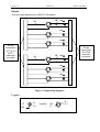
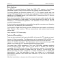
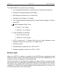
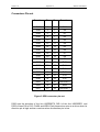
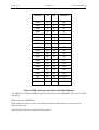
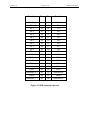
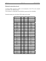
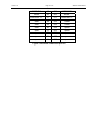
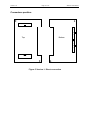
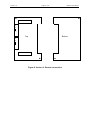
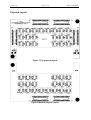
SMT373
User Manual
This Document is intended only for the use of the individual or entity to which it is
addressed and contains information that is privileged and confidential. If the reader of
this message is not the intended recipient or the employee or agent responsible for
delivering the message to the recipient, you are hereby notified that any
dissemination, distribution or copying of this communication is strictly prohibited. If
you have received this communication in error, please notify sender immediately by
telephone and return the original message to sender. Thank you.
User Manual (QCF42); Version 3;8/11/00 © Sundance Multiprocessor Technonlogy Ltd. 2000
Version 1.8
Page 2 of 15
SMT373 User Manual
Revision History
Date
Comments
17/09/99
Initial release
12/10/99
Pin-out name modified
possibility added
31/10/99
Engineer
Version
J.V.
1.0
RS422/485 J.V.
1.1
Physical layout added
J.V.
1.2
05/11/99
External connector pin-out
J.V.
1.3
18/11/99
Height of the module added
J.V.
1.4
28/02/00
External connector pin-out update
J.V.
1.5
07/04/00
Storage temperature added
J.V.
1.6
30/11/00
Changed the document layout to the new M.A.
template. Also changed some of the text so it
used a consistent font.
27/01/05
Pinout corrected for DIR2 and DIR0
and
Update for shb compatibility using shb2sdb
adaptor.
J.V.
1.7
1.8
Version 1.8
Page 3 of 15
SMT373 User Manual
Table of Contents
Table of Contents ....................................................................................................... 3
Table of figure............................................................................................................. 4
Scope ......................................................................................................................... 5
Scope ......................................................................................................................... 5
Main features.............................................................................................................. 6
Technical Description ................................................................................................. 6
Module height ............................................................................................................. 7
Connectors Pin-out..................................................................................................... 8
External connector pin-out........................................................................................ 11
Connectors position.................................................................................................. 13
Physical Layout ........................................................................................................ 15
Version 1.8
Page 4 of 15
SMT373 User Manual
Table of figure
Figure 1 Connectivity diagram .................................................................................... 5
Figure 2 SDB connector pin-out ................................................................................. 8
Figure 3 LVDS connector pin-out ............................................................................. 10
Figure 4 External connector pin-out.......................................................................... 12
Figure 5 Version 1: Direct connection....................................................................... 13
Figure 6 Version 2: Remote connection ................................................................... 14
Figure 7 Top physical layout..................................................................................... 15
Figure 8 Bottom physical layout................................................................................ 15
Version 1.8
Page 5 of 15
SMT373 User Manual
Scope
This document describes the SMT373 I/O module.
18
18
100 Ω
18
100 Ω
100 Ω
40-way
connectors
40-way
connectors
23 TTL or
LVTTL
usable per
connector
18
18
20 LVDS
pairs per
connector
100 Ω
18
100 Ω
100 Ω
Figure 1 Connectivity diagram
Legend
D
EN
DD+
Signifies
EN
D
DD+
Version 1.8
Page 6 of 15
SMT373 User Manual
Main features
The SMT373 converts Sundance Digital Bus SDB LVTTL signals to Low-Voltage
Differential Signals (LVDS) and can connect two systems several meters apart.
The board operates a conversion between LVTTL (TTL tolerant) signals and Low
Voltage Differential Signals. It provides two bi-directional 20-bit channels that can
transfer up to 2 GBytes/s thanks to 40 SN65LVDM176 transceivers from TI that can
individually reach 400Mbits/s.
Each channel provides 16 bits of data, a clock and a clock-enable signals with their
direction controlled by a single signal. Two other signals can be used for the bus
arbitration in a bi-directional application. The direction of each of them can be
controlled independently.
All the direction control signals are accessible through the connectors and therefore
can be set by the board they are connected to.
The Sundance Digital Bus already provides 200Mbytes/s data transfer rate between
TIMs. Thanks to this module a TIM can communicate with another board several
meters away.
It only requires 3.3V Power supply.
Technical Description
There are two versions of the board, which differ in the way the TTL signals are input.
Version 1: Direct connection. The Mezzanine card is connected PCB to PCB on a
carrier TIM through well-positioned SDB connector as they are on the SMT358.
Version 2: Remote connection. The Mezzanine card is connected through SDB
cables. It only needs the 3.3V provided through the mounting holes.
The board uses LVDM transceivers. They are TIA/EIA-644 standard compliant
devices except that the output current of the drivers is doubled. The board is
compatible with LVDS drivers and has 100Ω termination resistors. It is compatible
with LVDS receivers because it outputs twice the current of a LVDS driver and
therefor will keep the same voltage for a double terminated line. In half-duplex
transmissions it has the advantage to keep the voltage as in unidirectional
transmissions whereas LVDS would have reduced it by two due to the double
terminated lines.
If the line is not driven or in open-circuit, the output is forced high.
Version 1.8
Page 7 of 15
SMT373 User Manual
The SN65LVDM176 main features are following:
•
Low-Voltage Differential Driver and Receiver for Half-Duplex Operation
•
Designed for Signalling Rates of 400 Mbit/s
•
ESD Protection Exceeds 12 kV on Bus Pins
•
Operates from a Single 3.3 V Supply
•
Low-Voltage Differential Signalling with Typical Output Voltages of 350 mV
and a 50 Ω
•
Load Propagation Delay Times
Driver: 1.7 ns Typical
Receiver: 3.7 ns Typical
•
Power Dissipation at 200 MHz
Driver: 50 mW Typical
Receiver: 60 mW Typical
•
LVTTL Levels are 5 V Tolerant Bus Pins are High Impedance when
Disabled or With VCC Less Than 1.5 V Open-Circuit
•
Fail-safe receiver
•
Characterised for operation from -40°C to 85°C.
•
Storage temperature range from -65°C to 150°C.
Module height
When the SMT373 is directly connected to the SMT358 as a piggy-back board
(Direct connection version) the resulting height with the top LVDS cables fitted is 1,25
inches (3 cm) from the top layer of the carrier board.
The Remote version of the board can be fitted on a spare TIM site or anywhere else
(as long as 3.3V is provided) and uses SDB cables to be connected to the module.
The height of the module itself including the connectors is 0.5 inches (1.3 cm). So for
example on a TIM slot the maximum height with the cable fitted is 0.75 inches (1.9
cm) from the top layer of the carrier board.
Version 1.8
Page 8 of 15
SMT373 User Manual
Connectors Pin-out
Function
Pin
Pin
Function
GND
2
1
CLK
GND
4
3
D0
GND
6
5
D1
GND
8
7
D2
GND
10
9
D3
GND
12
11
D4
GND
14
13
D5
GND
16
15
D6
GND
18
17
D7
GND
20
19
D8
GND
22
21
D9
GND
24
23
D10
GND
26
25
D11
GND
28
27
D12
GND
30
29
D13
GND
32
31
D14
GND
34
33
D15
DIR2
36
35
USERDEF0
DIR0
38
37
WEN
DIR1
40
39
USERDEF1
Figure 2 SDB connector pin-out
DIR0 sets the direction of the line USERDEF0, DIR1 of the line USERDEF1 and
DIR2 of lines D0 to D15, CLKIN and WEN. Each transceiver acts as a driver when its
direction pin is high and as a receiver when its direction pin is low.
Version 1.8
Page 9 of 15
SMT373 User Manual
Function
Pin
Pin
Function
GND
2
1
CLK
GND
4
3
D0
GND
6
5
D1
GND
8
7
D2
GND
10
9
D3
GND
12
11
D4
GND
14
13
D5
GND
16
15
D6
GND
18
17
D7
GND
20
19
D8
GND
22
21
D9
GND
24
23
D10
GND
26
25
D11
GND
28
27
D12
GND
30
29
D13
GND
32
31
D14
GND
34
33
D15
NC
36
35
USERDEF0
DIR0
38
37
WEN
DIR1
40
39
USERDEF1
Figure 3 SDB connector pin-out for shb2sdb adaptors
The SMT373 is modified. DIR0 sets the direction of the line USERDEF0, D0 to D15, CLKIN
and WEN.
DIR1 of the line USERDEF1.
Each transceiver acts as a driver when its direction pin is high and as a receiver when its
direction pin is low.
This allows for direction control and flow control.
Version 1.8
Page 10 of 15
SMT373 User Manual
Function
Pin
Pin
Function
CLKIN +
2
1
CLKIN -
D0 +
4
3
D0 -
D1 +
6
5
D1 -
D2 +
8
7
D2 -
D3 +
10
9
D3 -
D4 +
12
11
D4 -
D5 +
14
13
D5 -
D6 +
16
15
D6 -
D7 +
18
17
D7 -
D8 +
20
19
D8 -
D9 +
22
21
D9 -
D10 +
24
23
D10 -
D11 +
26
25
D11 -
D12 +
28
27
D12 -
D13 +
30
29
D13 -
D14 +
32
31
D14 -
D15 +
34
33
D15 -
USERDEF0 +
36
35
USERDEF0 -
WEN+
38
37
WEN -
USERDEF1 +
40
39
USERDEF1 -
Figure 3 LVDS connector pin-out
Version 1.8
Page 11 of 15
SMT373 User Manual
External connector pin-out
A 68-way SCSI connector is fitted on the back-plate of the PC for the external
transmission. Ref: SMT373-CAB.
The connector is a HARTING 60 04 068 5344 (screw lock 60 01 000 9020).
Standard twisted pair or flat ribbon SCSI cables can be used.
Signal Name
Pin
Pin
Signal Name
Open
1
35
open
Open
2
36
open
Open
3
37
open
Open
4
38
open
Open
5
39
GND
GND
6
40
GND
GND
7
41
GND
CLKIN +
8
42
CLKIN -
D0 +
9
43
D0 -
D1 +
10
44
D1 -
D2 +
11
45
D2 -
D3 +
12
46
D3 -
D4 +
13
47
D4 -
D5 +
14
48
D5 -
D6 +
15
49
D6 -
D7 +
16
50
D7 -
D8 +
17
51
D8 -
D9 +
18
52
D9 -
D10 +
19
53
D10 -
D11 +
20
54
D11 -
D12 +
21
55
D12 -
D13 +
22
56
D13 -
D14 +
23
57
D14 -
D15 +
24
58
D15 -
Version 1.8
Page 12 of 15
SMT373 User Manual
USERDEF0 +
25
59
USERDEF0 -
WEN+
26
60
WEN -
USERDEF1 +
27
61
USERDEF1 -
GND
28
62
GND
GND
29
63
GND
GND
30
64
open
open
31
65
open
open
32
66
open
open
33
67
open
open
34
68
open
Figure 4 External connector pin-out
Version 1.8
Page 13 of 15
SMT373 User Manual
Connectors position
LVDS0
S
D
B
0
Top
Bottom
S
D
B
1
LVDS1
Figure 5 Version 1: Direct connection
Version 1.8
Page 14 of 15
SMT373 User Manual
LVDS0
S
D
B
0
Top
Bottom
S
D
B
1
LVDS1
Figure 6 Version 2: Remote connection
Version 1.8
Page 15 of 15
Physical Layout
Figure 7 Top physical layout
Figure 8 Bottom physical layout
SMT373 User Manual