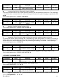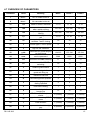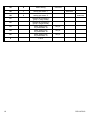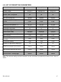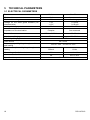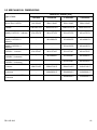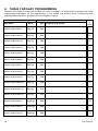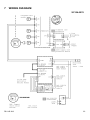
1
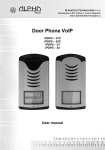
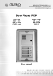
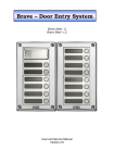
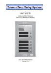
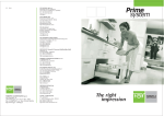
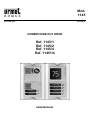
Mod.
1145
DS1145-019
LBT8072
COMBIPHONE OUT DOOR
Ref. 1145/1
Ref. 1145/2
Ref. 1145/4
Ref. 1145/14
USER MANUAL
TABLE OF CONTENTS
TABLE OF CONTENTS................................................................................................ 2
1
BASIC DESCRIPTION ............................................................................. 3
1.1
1.2
1.3
Features.................................................................................................... 3
Module Assembly ..................................................................................... 3
Module Features....................................................................................... 4
NUDV Basic Module
4 Buttons Module 1145/4, 1145/14
1.4
Installation of Guard Assembly ................................................................. 7
Installation on Plaster
Flush-Mounted Installation
2
2.3
Guard
8
Call............................................................................................................ 8
2.3.1
2.3.2
Outgoing Call
Incoming Call
8
8
PROGRAMMING OF PARAMETERS................................................................. 9
3.1
Programming through Phone.................................................................... 9
3.1.1
3.1.2
4
7
7
ALL-PURPOSE GUARD OPERATION ............................................................... 7
2.1
Signaling Overview ................................................................................... 7
2.2
Combi Out Door........................................................................................ 8
2.2.1
3
4
6
Entry to Programming
Programming of parameters
9
9
6
7
DESCRIPTION OF PARAMETERS .................................................................. 10
4.1
Direct Dialing – Memories....................................................................... 10
4.2
Switches.................................................................................................. 10
4.3
Basic Parameters ................................................................................... 11
4.4
Time Parameters .................................................................................... 12
4.5
Presetting and Deleting .......................................................................... 14
4.6
Programming Termination ...................................................................... 14
4.7
Overview of Parameters ......................................................................... 15
4.8
List of Presetting Parameters ................................................................. 17
TECHNICAL PARAMETERS............................................................................. 18
5.1
Electrical Parameters.............................................................................. 18
5.2
Mechanical dimensions .......................................................................... 19
TABLE FOR EASY PROGRAMMING ............................................................... 20
WIRING DIAGRAM............................................................................................ 23
2
DS1145-019
5
1
BASIC DESCRIPTION
1.1 FEATURES
•
•
•
•
•
•
•
•
•
•
•
•
•
•
•
•
•
•
•
Modular system allows to connect max 64 buttons
Voice communication is supplied only from telephone line
Impulse and tone dialing (DTMF)
Two 16digit numbers with each button (day/night mode)
Day/night switching
Possibility of the call extension by * or # choice
Possible to connect two independent locks for door opening (DTMF activation)
Possible use of 5 switch modes (e.g. camera, lighting, gradual opening)
Two codes for hanging up the guard from telephone
Two codes for door opening from telephone
Optional number of rings before taking an incoming call
Optional time among button pressing by code entry
Optional time of hanging up when the choice is repeated
Optional time before choice start
Optional parameters of tone choice, length of Flash and Pause
Possible programming by remote control
Integrated heating of printed circuit for climatically hostile atmospheres installation
Permanent lighting through visiting cards (optional power supply)
Protection against static electricity
1.2 MODULE ASSEMBLY
The Door Guard structural elements are the basic modules with two (1145/2) or one (1145/1) buttons and
extending button module 1145/4 and 1145/14 with four buttons.
1145/2
1145/62
DS1145-019
1145/1
1145/312
1145/612
1145/4
1145/14
1145/712
1145/52
3
Examples of frame configuration
1.3 MODULE FEATURES
NUDV Basic Module
The 1145 basic module is supplied in two variants, with two buttons 1145/2 and one button 1145/1.
Setting volume of
speaker
Programming jumper (short –
don’t needed password)
Setting volume of
microphone
1145/4
Expansion
Jumper – short is switch on
temperature heating basic
board
TRH
Setting level for
activation microphone
Connect flat cable for
extending up to 64 buttons or
for connect keyboard
Connect telephone line
Connecting to earth –
protect against static
electricity
Contact 1 switch
Contact 2 switch
Power supply 12V ac/dc
For two switches, lighting
heating
and
Fig. 1 Rear view of basic module
To ensure the basic function the terminal “a b LINE” can be connected to a PABX extension. It is
connected in the same way as any telephone to any branch exchange to the maximum distance of 300m.
The guard’s circuits are supplied from telephone line, so that nothing should be connected for voice
communication.
If one or two switches are necessary to be used, the A.C. voltage of min. 10Vst - max. 15V or D.C. voltage
of min. 12V to max. 18V must be energized to "12V" terminal. This source loading depends on number of
modules, since it simultaneously serves feeding of lighting through visiting cards – at max. number of
connected modules the demand will not exceed 300mA. This source can be also used for feeding of
lock(s), and then it is necessary to consider the electrical lock demand. In practice the alternating feeder
12V/1A mostly meets these demands.
The connection of switch contact terminals is shown on fig. 1. The "NO" designation means an idledisconnected contact, "COM" means a pin contact (middle) and "NC" means an idle-connected contact.
The contacts of both switches are galvanically isolated each other and from other guard circuits.
The variants of connection are shown on fig. 2.
The "G" Faston 2.8mm necessary to connect the device to earthing.
The "HEAT" jumper serves the switching of board heating. This function requires the connection of 12V
supply on "12V" marked terminal.
The "EXPANSION" marked connector serves the connection of extending modules by means of flat cable.
The "PRG" marked connector provides the guard adjustment from PC by means of serial cable (KAB) and
serves to the service for diagnostics and new software load.
The "SERVICE" jumper serves to direct access to programming. It can be used, for example by absence of
password for programming.
4
DS1145-019
Note: It’s better to connect the device on the expansion not interested to the emergency condition (when
the power supply is not connected)
1145/1-2
1145/1-2
For lighting and control
of switch
Power
Supply
12V/1A
Lock 1
Lock 2
Power.
Aliment
Supply
12V/0.3A
12V/0,3A
Lock 1
Lock 2
For power lock
(other voltage)
1145/1-2
+
Camera
Electromagnetic
holding lock
-
Power
Aliment.
Supply
12Vcc with
12Vcc
back-up
Lock 1
Power
Aliment.
Supply
24V/1A
24V/1A
Additional bell
Power
Aliment.
Supply
12V/1A
12V/1A
Fig. 2 Examples of switch connections
Setting voice communication
Position trimmers are presetting from manufacture and in majority case agree with, therefore changes
setting altering only in necessary case.
Trimmer "MIC" be instrumental to setting loudness of microphone, trimmer "SPK" be instrumental to setting
loudness loudspeaker. In this version is big reserve in gain, therefore isn't recommended adjust more than
on half, typical is in 1/3 from minimum gain. Trimmer "TRH" be instrumental to setting levels activation of
microphone, it means, so as doorphone "non whoop" owing to acoustic loop so selection, which direction
has priority, whether from microphone, or into loudspeaker. Level from which volume with "switch on"
direction from microphone doorphone setting trimmer „TRH". This setting interact level surrounding noise
and setting gain of microphone „MIC".
Progress of setting: setting the TRH, SPK and MIC trimmer like in figure (base setting) and test the
comunication. Setting the SPK and MIC trimmer if there are problems or particular working situation.
DS1145-019
5
Other Setting
If the audio level of the telephone is too low set the MIC trimmer in hour sense until the level is good.
If the audio level of the telephone is too high set the MIC trimmer in anti hour sense until the level is good.
If the audio level of Combiphone Out Door (1145/X) speaker is too low set the SPK trimmer in hour sense
until the level is good
If the audio level of Combiphone Out Door (1145/X) speaker is too high or distorted set the SPK trimmer in
anti hour sense until the level is good
If after these setting the audio level is not satisfactory set the TRH trimmer in hour sense.
Note: In case of regulation of TRH trimmer it could be necessary to set again the SPK and MIC trimmer.
4 Buttons Module 1145/4, 1145/14
This module is supplied in two designs. The Ref.1145/4 module has four buttons and includes the
electronics to be connected to the basic module or to previous Ref.1145/4 module. This module is only
connected by flat cable – buttons and lighting through is already interconnected, the flat cable connection is
facilitated by connector locks, preventing from rotation, but to keep the connection routing is imperative.
The Ref.1145/14 module is always connected to previous Ref.1145/4. The connection is not prepared and
should be done by conductors (see system installation).
Connection flat cable
direction
to
basic
modul
Connection flat cable
direction to 1145/4
1145/X
To
1145/84
To 1145/4
1145/X
1145/4
1145/4
Alternative connect
power for lighting
Connecting 4 buttons
and common (GND)
Connecting two
wires use for
connect power for
lighting
1145/14
1145/4
1145/14
1145/14
Fig. 3 Connection of 1145/4 to 1145/14 and connection of modules
6
DS1145-019
1.4 INSTALLATION OF GUARD ASSEMBLY
Installation on Plaster
By installation on plaster the only compact box 1145/5X - Rain-Protective
Cover 1145/3XX is used, which will supersede all mechanical parts. The
installation is made by screwing to the wall by means of dowels. See 1145/311
on figure.
Flush-Mounted Installation
The 1145/5X mounting box is built-in wall. Be careful in orientation of assembling holes when nearly
1145/51 square box is used – it must be in vertical axis.
The Protecting Frame (provides overlapping of unevenness after mounting box walling-in) and Canopy
(necessary for installation in external areas) form other accessories for flush-mounted installation. When
installed in surroundings with possible water condensation (temperature changes) or rain, it is
recommended to connect the jumper on basic module – heating ON.
The board heating has two positive functions partly it heats up the electronics in winter and partly avoids
water condensation occurs on basic guard board.
2
ALL-PURPOSE GUARD OPERATION
2.1 SIGNALING OVERVIEW
The all-purpose guard signals an acoustic conditions they may occur during operation. Another signaling
can be done by means of red LED (placed under microphone hole). You can listen the signaling samples
in Nset setting program.
Condition
Tones
Tone frequency
LED
Line lifting up
–▄–■–▀–
425-850-1275
glows
Line hanging up
–▀–■–▄
1275-850-425
goes
out
Report after calling
–▄–■–▀–
425-850-1275
glows
––█––
425
Command
phone
confirmation
from
Dialing
goes
out
DTMF/Pulse
Call
glows
Notice about call end
–■–■–■–
1275
glows
Entry to programming from phone
–■–■–■–
850
glows
––▓–▓–––––
mod. 850
glows
Programming from phone
Parameter confirmation
Connection to line (Reset)
––█––
glows
–■–▄–■–
1275-850-1275
Error (anything, if unsuitable)
–■–■–■–■–■–■–
425….
Empty memory (no progr. numb.)
–█–▄–■–▄–■–▄–
850-1275-1700…
DS1145-019
blinks
7
2.2 COMBI OUT DOOR
The Combi out door is influenced partly by used guard assembly and partly by setting of guard parameters
(see chapter “Parameter Overview”).
2.2.1
Guard
The guard buttons are provided by nameplates or positions of persons inside the object. The incoming
person will press the corresponding button, the guard will lift up the line neither immediately (the button is
not the first number from code lock), or with delay (parameter 53) and after period given by parameter 55
will dial the programmed phone number. The dialing number differs by choice mode, which is set in the
guard (parameter 47):
•
Day/night mode = being the guard in Day mode, so it is always dialing a number set in
parameter 1, in Night mode, it is always dialing a number set in parameter 2. The mode
switchover is set in parameters 45,46.
•
mode of second number group = first press – it always dials a number set in parameter 1. By
repeated press of the same button or detection of busy tone after dialing the guard will select the
number from the second group (parameter 2). The next press of the same button again selects a
number of the first group, etc..……
If a visitor presses the button after guard lifting up, so the guard will hang up for a period given by
parameter 54, lift up the line and dial a new number. The number choice is carried out both tone (DTMF),
and pulse dialing according to parameter 41 setting.
2.3 CALL
2.3.1
Outgoing Call
The outgoing call is the call from guard (caused by visitor) to the telephone. After guard choice the
telephone is ringing inside object and the lifting up will allow speaking to the visitor at door. It’s possible
with DTMF code
•
close the switch (parameter 35)
•
change over the Day/Night modes (parameters 45,46)
•
hang up (parameter 43).
The guard in 10 seconds before call end (parameter 52) will send a notice about call end and the call may
be extended by sign selection (parameter 42). The telephone hanging up will end the call (the exchange is
sending a busy tone on guard’s line and the guard also will hang up).
To end the call digit the default number 34 (parameter 43), if you don’t digit that number the call end will
arrive from PABX if it recognize the tone or when the conversation time, setting from parameter 52 (1
minute default), will finish.
2.3.2
Incoming Call
The incoming call is the call from guard (caused by person inside object). After exchange number selection,
where the guard is connected, the guard’s line is ringing and when set number of rings is over (parameter
51), the guard will lift up and it is possible to speak. The possibilities are the same as with outgoing call
(Chapter 2.3.1).
Except the first 10 seconds, where extra "# and service password" (parameter 44) can be entered, the
guard then will proceed with programming mode.
The other exception of incoming call is by connected “SERVICE” jumper. The guard after line lifting up
proceeds then with programming mode (without service password).
To end the call digit the default number 34 (parameter 43), if you don’t digit that number the call end will
arrive from PABX if it recognize the tone or when the conversation time, setting from parameter 52 (1
minute default), will finish.
8
DS1145-019
3
PROGRAMMING OF PARAMETERS
3.1 PROGRAMMING THROUGH PHONE
3.1.1
Entry to Programming
The all-purpose door guard will be set to programming mode in two ways:
1.
by password – hook off the telephone and dial a number, where the guard is connected. The
guard will answer (you hear tone for answering – see Chapter 2.1 of complete manual) up to
10 sec dial #xxxx, where xxxx is the service number for entry to programming and if O.K., the
registration tone to programming will sound and afterwards the programming tone is heard.
2.
by "SERVICE" jumper – you will realize the connection with guard in the same way as in art. 1,
but when the SERVICE jumper is connected, then the guard after answering directly comes to
programming mode – you hear tone for answering, registration tone to programming and
afterwards the programming tone is heard.
3.1.2
Programming of parameters
The initial state for programming is signaled by programming tone and the guard will come back to this
state always after time expiration (5 seconds) even if the programming is not finished.
When programming two types of parameters will occur. Partly they are parameters with fixed length – the
majority of them they are, then the programming is affirmed and the parameter is always recorded
immediately after mandatory length fulfillment by acknowledge tone and partly the parameters with variable
length (parameter 1,2,32,33,34), followed with confirmation and the recording of the parameter after
inactivity period expires (5 sec). The only case with immediate recording of parameters is the fulfillment of
max. number of recorded signs (numbers) – by parameters 1 and 2 it is 16, by parameters 32,33,34 it is 6.
If during programming you enter number (sign) not allowable by its extent then the guard immediately emits
an error tone, the parameter will not be recorded nor changed, the guard will come to initial state and it is
possible to repeat the parameter setting or program another parameter.
The guard stays inactive in programming mode for 34 seconds, then he will automatically hang up. By
every dialing of DTMF tone this period is set up repeatedly. The selection of parameter 9 can also end the
programming mode.
Note: if you wish to keep the connection (extend the 34 seconds period) than the customer will think over
the other setting, so pressing e.g.. 6, 7, 0, * or # form time to time will be sufficient and the guard
immediately responds by error tone, but he will extend the period to hanging up..
Note: The # sign is not used by entering of 32,33,34 parameters can be used for immediate parameter
entering.
DS1145-019
9
4
DESCRIPTION OF PARAMETERS
4.1 DIRECT DIALING – MEMORIES
Parameter
Value
Meaning
Basic
Exam.1
Exam.2
1
tt nn…
No. nn under button tt
-
-
-
tt
nn
Button number (memory), always set in two-digit manner [01-64]
telephone number up to 16 digits, we want to store. To store other choice
flags the assignment given in table is used.
The numbers stored in parameter 1 are the number of the first group or numbers of
Day mode.
Neither basic setting nor settings per examples do not change or delete the stored
numbers.
mean.
0-9
#
*
Flash
Pause
choice
0-9
#
**
*#
*0
Parameter
Value
Meaning
Basic
Exam.1
Exam.2
2
tt nn…
No. nn under button tt
-
-
-
tt
nn
Button number (memory), always set in two-digit manner [01-64]
telephone number up to 16 digits, we want to store. To store other
choice flags the assignment given in table is used..
The numbers stored in parameter 2 are the number of the second group or
numbers of Night mode.
Neither basic setting nor settings per examples do not change or delete the stored
numbers.
List of related parameters: 41 45 46 47 48 49 57 58 59 50 81 82
mean.
0-9
#
*
Flash
Pause
choice
0-9
#
**
*#
*0
4.2 SWITCHES
Parameter
Value
Meaning
Basic
Exam.1
Exam.2
31
rm
switch r works in m mode
11 21
11 22
11 25
r
m
m=1
switch number [1-2]
switch mode [for r=1 1-4 , for r=2 1-5]
switch mode – it will close on command or password for ss period (used for electrical locks, gate
opening etc.)
m=2
camera mode – it will close by guard lifting up and open by hanging up.
m=3
lighting mode – it will close by guard lifting up and stay closed even for ss period after guard
hanging up (the line is engaged for this period).
m=4
switch mode – it will close after button pressing and open after ss period (used for e.g. external
bell or horn connections).
m=5
gradual opening mode – in this mode the only switch 2 will be set together with switch 1 set to
mode 1. The switch 1 is activated for ss period, then the time xx is proceeding before switch 2
closing. Then the switch 2 is activated for ss period and afterwards the guard hangs up.
Note: The only switch 1 can be activated from phone and all sequence started. Besides that the switch 2
can be separately activated from buttons by password.
List of related parameters: 32 33 34 35 36 37 38 8# 83
10
DS1145-019
Parameter
Value
Meaning
Basic
Exam.1
Exam.2
35
r aa
command aa from phone
after r switch closing
155 266
155 266
155 266
r
switch number [1-2]
aa
command from phone after switch closing [2 digits]
The same command can be set for both switches, then they are activated at the same time. The advantage
is to set the same command both for switch closing and command to guard hanging up (parameter 43)
aa=bb.
List of related parameters: 31 36 37 38 43 8# 83
Parameter
Value
Meaning
Basic
Exam.1
Exam.2
36
r ss
ss period [sec] of r switch
closing
105 205
102 202
105 205
r
switch number [1-2]
ss
duration of switch closing [2 digits 01-99]
List of related parameters: 31 32 33 34 35 37 38 8# 83
Parameter
Value
Meaning
Basic
Exam.1
Exam.2
37
rp
r switch control by incoming
call
11 21
11 21
11 21
r
switch number [1-2]
p
parameter, if p=1 allowed or p=0 prohibited to control the switch during incoming call.
To prohibit the control during incoming call is important e.g. when using switch 2 in mode 1 for control of
garage gate opening, when the electronics opens the gate and the gate is closed by car passage. Then the
control from phone could undesirably cause the permanent gate opening (not closed – no car passage).
List of related parameters: 31 35 8# 83
Parameter
38
Value
Meaning
Basic
Exam.1
Exam.2
xx
xx period [sec] between
switches 1 and 2 closing
10
10
15
xx – time between close switches 1 and 2 by m=5 mode setting (gradual opening) [2 digits 01-99]
List of related parameters: 31 32 33 34 35 36 37 8# 83
4.3 BASIC PARAMETERS
Parameter
Value
Meaning
Basic
Exam.1
Exam.2
41
v
choice type v – tone / pulse
0
0
0
v
choice type v=0 is DTMF tone choice, v=1 is pulse choice
List of related parameters: 1 2 8# 84
z
Parameter
Value
Meaning
Basic
Exam.1
Exam.2
42
z
sign for call extension
*
*
*
sign for call extension * or # (10sec before call end the guard will send a notice, then the call may
be extended)
List of related parameters: 52 8# 84
DS1145-019
11
Parameter
Value
Meaning
Basic
Exam.1
Exam.2
43
g bb
command for guard hanging
up from phone
134 235
155 244
155 244
g
command order [1-2] (two commands in order to hang up the guard using both switches)
bb
command for guard hanging up from phone [2 digits]
List of related parameters: 35 8# 84
Parameter
Value
Meaning
Basic
Exam.1
Exam.2
44
xxxx
service password
0000
0000
0000
xxxx
service password for entry to programming
List of related parameters: 8# 84
Parameter
Value
Meaning
Basic
Exam.1
Exam.2
45
dd
command for DAY switching
11
11
11
46
nn
command for NIGHT
switching
10
10
10
dd
command for DAY mode switching [2 digits]
nn
command for NIGHT mode switching [2 digits]
Note: The switchover to Day/Night mode remains set in guard even after line disconnection.
List of related parameters: 1 2 33 34 47 8# 84
Parameter
Value
Meaning
Basic
Exam.1
Exam.2
47
e
mode of guard choice
1
1
0
e
mode of guard choice e=0 selects numbers of the first and second groups, e=1 selects number
per Day/Night guard mode.
List of related parameters: 1 2 8# 84
Parameter
Value
Meaning
Basic
Exam.1
Exam.2
48
c
keyboard connection
0
0
1
c
c=0 only NC-mode connected to the basic module
ATTENTION: This parameter setting will sharply influence whole guard function.
List of related parameters: 1 2 32 33 34 47 49 53 8# 84
4.4
TIME PARAMETERS
Parameter
Value
Meaning
Basic
Exam.1
Exam.2
51
q
number of rings before
guard call lifting up
2
1
2
q
Number of incoming call rings, the guard lifts up among rings namely 2 sec. after detection q –
times rings. The number can be set from 1 to 9.
List of related parameters: 44 8# 85
12
DS1145-019
Parameter
Value
Meaning
Basic
Exam.1
Exam.2
52
d
max. call time
1
2
1
d –
max. time, for which the guard is hanging up, this time can be extended
during call by sign choice from telephone (* or #). Time setting is per table.
List of related parameters: 42 8# 85
time [min]
0,5
1-9
15
30
choice
0
1-9
*
#
Parameter
Value
Meaning
Basic
Exam.1
Exam.2
53
w
time among button presses
2
2
2
w
max. time [sec] among button presses [range 1-9]
Note: switch closing – if time between two next presses is bigger than w time, the code is not evaluated
correctly.
List of related parameters: 1 2 32 33 34 47 48 49 8# 85
Parameter
Value
Meaning
Basic
Exam.1
Exam.2
54
z
time of hanging up when
dialing repeated
2
2
2
z
time [sec] for which the guard will hang up, before repeated dialing (button pressing during call or
dialing, busy tone detection) [range 1-5]
List of related parameters: 8# 85
Parameter
Value
Meaning
Basic
Exam.1
Exam.2
55
z
time before dialing
1
1
1
z
time [sec] after guard lifting up before dialing [range 1-5]. This time is different for each
exchange, but most central exchanges usually manage to process dialing up to 2 seconds after
line lifting up.
List of related parameters: 8# 85
Parameter
Value
Meaning
Basic
Exam.1
Exam.2
56
h
number of rings before
hanging up
12
12
12
h
after finishing the dialing it calculates number of KVT (ringing tones). If the number exceeds h
value, it will hang up [range 04-99]. The dialing is repeated in case, when the dialing mode of 2
groups is set.
List of related parameters: 47 8# 85
Parameter
Value
Meaning
Basic
Exam.1
Exam.2
57
t
DTMF tone duration (tone)
choice
5 (100ms)
5 (100ms)
5 (100ms)
DS1145-019
13
58
m
gap duration among DTMF
tones
5 (100ms)
5 (100ms)
5 (100ms)
59
f
Flash duration
1 (100ms)
1 (100ms)
1 (100ms)
50
p
pause duration / interdigit
gap
8 (800ms)
8 (800ms)
8 (800ms)
t
DTMF tone duration is determined per formula:
(entered number + 5) x 10 = tone duration [ms]
[range 1-0 i.e. 60-150ms]
gap duration among DTMF tones is determined per formula:
(entered number + 5) x 10 = gap duration [ms]
[range 1-0 i.e. 60-150ms]
Flash duration is determined per formula:
entered number x 100 = Flash duration [ms]
[range 1-6 i.e. 100-600ms]
pause duration is determined per formula:
entered number x 100 = pause duration [ms]
[range 5-0 i.e. 500-1000ms]
p time is simultaneously the duration of interdigit gap at pulse dialing.
m
f
p
List of related parameters: 1 2 41 8# 85
4.5
PRESETTING AND DELETING
Parameter
Value
Meaning
Basic
8#
#
basic setting
executes
8#
1
setting per exam. 1
8#
2
setting per exam. 2
Exam.1
Exam.2
executes
executes
This setting does not influence 1 and 2 (numbers stored in memory)
Parameter
Value
81
82
83
84
85
Meaning
Basic
deletes all numbers in
group 1 (Day mode)
deletes all numbers in
group 2 (Night mode)
basic setting only
for parameters 3x
basic setting only
for parameters 4x
basic setting only
for parameters 5x
only 3..
Exam.1
Exam.2
only 4..
only 5..
The parameters 81 and 82 will execute deleting of all numbers stored in memories for buttons.
The parameters 83 – 85 will execute a selective basic setting only for parameters starting with 3.. – 5..
ATTENTION the deleting is non-reversible !!!, It is then necessary to program it again.
4.6
Parameter
9
PROGRAMMING TERMINATION
Value
Meaning
Basic
Exam.1
Exam.2
END
After dialing 9 to programming tone the guard will hang up.
14
DS1145-019
4.7 OVERVIEW OF PARAMETERS
Parameter
Value
Meaning
Basic
Exam.1
Exam.2
1
tt nn…
No. nn under button tt
-
-
-
2
tt nn…
No. nn under button tt
-
-
-
31
rm
switch r works in m mode
11 21
11 22
11 25
35
r aa
155 266
155 266
155 266
36
r ss
105 205
102 202
105 205
37
rp
11 21
11 21
11 21
38
xx
10
10
15
41
v
choice type v – tone / pulse
0
0
0
42
z
sign for call extension
*
*
*
43
g bb
command for guard hanging
up from phone
134 235
155 244
155 244
44
xxxx
service password
0000
0000
0000
45
dd
command for DAY switching
11
11
11
46
nn
command for NIGHT
switching
10
10
10
47
e
mode of guard choice
1
1
0
51
q
number of rings before
guard call lifting up
2
1
2
52
d
maximum call time
1
2
1
53
w
time among button presses
2
2
2
54
z
time of hanging up when
dialing repeated
2
2
2
55
z
time before dialing
1
1
1
56
h
57
t
58
m
59
50
DS1145-019
command aa from phone
after r switch closing
ss period [sec] of r switch
closing
r switch control by incoming
call
xx period [sec] between
switches 1 and 2 closing
number of rings before
hanging up
DTMF tone duration (tone)
choice
gap duration among DTMF
tones
12
12
12
5 (100ms)
5 (100ms)
5 (100ms)
5 (100ms)
5 (100ms)
5 (100ms)
f
Flash duration
1 (100ms)
1 (100ms)
1 (100ms)
p
pause duration / interdigit
gap
8 (800ms)
8 (800ms)
8 (800ms)
15
8#
#
basic setting
8#
1
setting per exam. 1
8#
2
setting per exam. 2
81
82
83
84
85
9
16
deletes all numbers in
group 1 (Day mode)
deletes all numbers in
group 2 (Night mode)
basic setting only
for parameters 3x
basic setting only
for parameters 4x
basic setting only
for parameters 5x
executes
executes
executes
only 3..
only 4..
only 5..
END
DS1145-019
4.8 LIST OF PRESETTING PARAMETERS
parameter
bas. cast.
example 1
example 2
Switch 1 mode
lock m=1
lock m=1
lock m=1
Switch 2 mode
lock m=1
camera m=2
prog. m=5
Switch 1 activ. from phone
55
55
55
Switch 2 activ. from phone
66
66
66
5 sec
2 sec
5 sec
Con. by incoming call
allowed
allowed
allowed
Delay among ap. during oper.
10 sec
10 sec
15 sec
Choice
DTMF
DTMF
DTMF
*
*
*
34 / 35
55 / 44
55 / 44
0000
0000
0000
Switching to day mode
11
11
11
Switching to night mode
10
10
10
Day/Night
Day/Night
2 groups
2
1
2
Max. call time
1 min
2 min
1 min
Time among button presses
2 sec
2 sec
2 sec
Time of hanging up when dialing
repeated
2 sec
2 sec
2 sec
Time before dialing
1 sec
1 sec
1 sec
Number of rings before hanging up
12
12
12
DTMF tone duration (tone) choice
100ms
100ms
100ms
Gap duration among DTMF tones
100ms
100ms
100ms
Closing time of switch 1 and 2
Sign of call extension
Hanging up from phone 1 / 2
Service password
Guard choice mode
Number of rings of incoming call
Flash duration
100ms
100ms
100ms
Pause duration / interdigit gap
800ms
800ms
800ms
Note: The minimum setting and both examples can be customized by expected purchase of min. 10pcs of
NUDV.
DS1145-019
17
5
TECHNICAL PARAMETERS
5.1 ELECTRICAL PARAMETERS
Parameter
Value
Conditions
Minimum line current
Minimum line voltage
18mA
18V
line answered
line hang up
Voltage on line while guard answers (VA
characteristics)
< 8V
< 12V
I = 20mA
I = 60 mA
Leakage in hang up status
< 50uA
U = 60V
Complex
line answered
Impedance of line termination
Band width
Impedance of ringing
Sensitivity of ringing detector
300Hz – 3400 Hz
> 2Kohm
min. 10 – 25 V
Pulse choice
Power supply of lighting through, switches
and heating
Max. consumption of lighting through and
heating
Max. voltage of switch contact
Max. current of switch contact
Operational temperature
18
20 - 60mA
25 – 60 Hz
40 / 60 ms
12V d.c. ± 2V , 10-12V a.c. ± 2V
300mA
12Vss
48V
2A
at I < 1A
at U < 30 V
- 20 to + 50°C
DS1145-019
5.2 MECHANICAL DIMENSIONS
Dimension HxWxD [mm]
Type of item
Mount. Box 1145/5X
Fixing frame
1145/6X
Rain protective cover (on
plaster) 1145/31X 1 column
1 module
2 modules
3 modules
4 modules
114x118x45
204x118x45
294x118x45
384x118x45
119x125x12.6
209x125x12.6
299x125x12.6
389x125x12.6
151x157x79
241x157x79
331x157x79
421x157x79
-
241x286x79
331x286x79
421x286x79
Rain protective cover (on
plaster) 1145/32X 2
columns
Rain protective cover (on
plaster) 1145/33X 3
columns
flush -mounted with canopy
1145/61X 1 column
-
-
331x415x79
421x415x79
151x157x47
241x157x47
331x157x47
421x157x47
flush -mounted with canopy
1145/62X 2 columns
-
241x286x47
331x286x47
421x286x47
flush -mounted with canopy
1145/63X 3 columns
-
-
331x415x47
421x415x47
flush -mounted 1145/71X
1 column
148x151x2.5
238x151x2.5
328x151x2.5
418x151x2.5
flush -mounted 1145/72X
2 columns
-
238x280x2.5
328x280x2.5
418x280x2.5
flush -mounted 1145/73X
3 columns
-
-
328x409x2.5
418x409x2.5
DS1145-019
19
6
TABLE FOR EASY PROGRAMMING
Complete the values in empty part of table you want to program. In double-frame part there are whole
programming commands, so the programming is very simple and without errors. Furthermore such
programmed values will be available for next changes in manual.
Meaning
Description
Programming sequence
Spec.
par. Complete your values
num.
of
point
Number under button 1
Day/1gr.
101
16
Number under button 2
Day/1gr.
102
16
Number under button 3
Day/1gr.
103
16
Number under button 4
Day/1gr.
104
16
Number under button 5
Day/1gr.
105
16
Number under button 6
Day/1gr.
106
16
Number under button 7
Day/1gr.
107
16
Number under button 8
Day/1gr.
108
16
Number under button 9
Day/1gr.
109
16
Number under button 10
Day/1gr.
110
16
Number under button 11
Day/1gr.
111
16
Number under button 12
Day/1gr.
112
16
Number under button 1
Night/2gr.
201
16
Number under button 2
Night/2gr.
202
16
Number under button 3
Night/2gr.
203
16
20
DS1145-019
Number under button 4
Night/2gr.
204
16
Number under button 5
Night/2gr.
205
16
Number under button 6
Night/2gr.
206
16
Number under button 7
Night/2gr.
207
16
Number under button 8
Night/2gr.
208
16
Number under button 9
Night/2gr.
209
16
Number under button 10
Night/2gr.
210
16
Number under button 11
Night/2gr.
211
16
Number under button 12
Night/2gr.
212
16
Switch 1 works in mode
m=1 - 4
311
1
Switch 2 works in mode
m=1 - 5
312
1
Clos. of switch 1 fr. phone
351
2
Clos. of switch 2 fr. phone
352
2
Closing time of switch 1
[sec]
361
2
Closing time of switch 2
[sec]
362
2
Sw. cont.1 by incoming
call
1/0
371
1
Sw. cont.2 by incoming
call
1/0
372
1
Time between 1 and 2
switch closing
[sec]
38
2
Tone/pulse tone choice
1/0
41
1
DS1145-019
21
Sign of call extension
*/#
42
1
1
431
2
2
432
2
Service password
44
4
Comm. to DAY switching
45
2
Comm.
switching
46
2
1/0
47
1
0/1/2/3
48
1
1/0
49
1
51
1
Guard
phone
hang.
up
from
Guard
phone
hang.
up
from
to
NIGHT
Guard choice mode
Keyboard connection
Keyboard mode
Number
ringing
of
rings
for
Maximum call duration
[min]
52
1
Time among button press.
[sec]
53
1
Hang. up time
dialing repeated
[sec]
54
1
[sec]
55
1
56
2
when
Time before dialing start
Num. of rings bef. hang.
up
Duration of dialing tone
(n+5)x10
57
ms
1
Gap among DTMF tones
(n+5)x10
58
ms
1
Flash duration
nx100
59
ms
1
Pause durat. / interdigit
gap
nx100
50
ms
1
22
DS1145-019
7
WIRING DIAGRAM
SC104-0076
DS1145-019
23
DS1145-019
FILIALI
20151 MILANO – V.Gallarate 218
Tel. 02.380.111.75 - Fax 02.380.111.80
00043 CIAMPINO (ROMA) V.L.Einaudi 17/19A
Tel. 06.791.07.30 - Fax 06.791.48.97
80013 CASALNUOVO (NA) V.Nazionale delle Puglie 3
Tel. 081.193.661.20 - Fax 081.193.661.04
30030 VIGONOVO (VE) – V.del Lavoro 71
Tel. 049.738.63.00 r.a. - Fax 049.738.63.11
66020 S.GIOVANNI TEATINO (CH) – V.Nenni 17
24 loc. Sambuceto Tel. 085.44.64.851
Tel. 085.44.64.033 - Fax 085.44.61.862
LBT8072
STABILIMENTO
URMET DOMUS S.p.A.
10154 TORINO (ITALY)
VIA BOLOGNA 188/C
Telef.
011.24.00.000 (RIC.AUT.)
Fax
011.24.00.300 - 323
Area tecnica
servizio clienti 011.23.39.810
http://www.urmetdomus.com
e-mail: [email protected]
DS1145-019