1
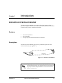
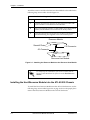
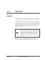
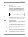
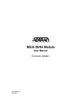
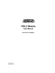
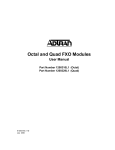
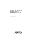
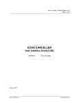
Resource Host Module
User Manual
Part Number 1200324L1
61200324L1-1A
May 2000
901 Explorer Boulevard
P.O. Box 140000
Huntsville, AL 35814-4000
(256) 963-8000
© 2000 ADTRAN, Inc.
All Rights Reserved.
Printed in U.S.A.
Federal Communications Commission (FCC) Radio Frequency Interference Statement
This equipment has been tested and found to comply with the limits for a Class A digital device, pursuant to Part 15 of the FCC Rules. These limits are designed to provide reasonable protection against
harmful interference when the equipment is operated in a commercial environment. This equipment
generates, uses, and can radiate radio frequency energy and, if not installed and used in accordance
with the instruction manual, may cause harmful interference to radio frequencies. Operation of this
equipment in a residential area is likely to cause harmful interference in which case the user will be required to correct the interference at his own expense.
Shielded cables must be used with this unit to ensure compliance with Class A FCC limits.
Change or modifications to this unit not expressly approved by the party responsible for compliance
could void the user’s authority to operate the equipment.
Warranty and Customer Service
ADTRAN will replace or repair this product within five years from the date of shipment if the product
does not meet its published specification, or if it fails while in service. For detailed warranty, repair, and
return information, refer to the ADTRAN Equipment Warranty and Repair and Return Policy Procedure (see the last page of this manual).
A return material authorization (RMA) is required prior to returning equipment to ADTRAN.
For service, RMA requests, or more information, see the last page of this manual for the toll-free contact
number.
iii
Limited Product Warranty
ADTRAN warrants that for five (5) years from the date of shipment to Customer, all products manufactured by ADTRAN will be free from defects in materials and workmanship. ADTRAN also warrants
that products will conform to the applicable specifications and drawings for such products, as contained in the Product Manual or in ADTRAN's internal specifications and drawings for such products
(which may or may not be reflected in the Product Manual). This warranty only applies if Customer
gives ADTRAN written notice of defects during the warranty period. Upon such notice, ADTRAN will,
at its option, either repair or replace the defective item. If ADTRAN is unable, in a reasonable time, to
repair or replace any equipment to a condition as warranted, Customer is entitled to a full refund of the
purchase price upon return of the equipment to ADTRAN. This warranty applies only to the original
purchaser and is not transferable without ADTRAN's express written permission. This warranty becomes null and void if Customer modifies or alters the equipment in any way, other than as specifically
authorized by ADTRAN.
EXCEPT FOR THE LIMITED WARRANTY DESCRIBED ABOVE, THE FOREGOING CONSTITUTES
THE SOLE AND EXCLUSIVE REMEDY OF THE CUSTOMER AND THE EXCLUSIVE LIABILITY OF
ADTRAN AND IS IN LIEU OF ANY AND ALL OTHER WARRANTIES (EXPRESSED OR IMPLIED).
ADTRAN SPECIFICALLY DISCLAIMS ALL OTHER WARRANTIES, INCLUDING (WITHOUT LIMITATION), ALL WARRANTIES OF MERCHANTABILITY AND FITNESS FOR A PARTICULAR PURPOSE. SOME STATES DO NOT ALLOW THE EXCLUSION OF IMPLIED WARRANTIES, SO THIS
EXCLUSION MAY NOT APPLY TO CUSTOMER.
In no event will ADTRAN or its suppliers be liable to Customer for any incidental, special, punitive,
exemplary or consequential damages experienced by either Customer or a third party (including, but
not limited to, loss of data or information, loss of profits, or loss of use). ADTRAN is not liable for damages for any cause whatsoever (whether based in contract, tort, or otherwise) in excess of the amount
paid for the item. Some states do not allow the limitation or exclusion of liability for incidental or consequential damages, so the above limitation or exclusion may not apply to Customer.
iv
Table of Contents
List of Figures ....................................................................................................................................................vii
Chapter 1
Introduction .............................................................................................................................. 1-1
Resource Host Module overview ................................................................................................................... 1-1
Features ....................................................................................................................................................... 1-1
Description.................................................................................................................................................. 1-1
Chapter 2
Installation ................................................................................................................................ 2-1
Unpack and Inspect .......................................................................................................................................... 2-1
ADTRAN Shipment Includes .................................................................................................................. 2-1
Option Slots and Network Interface Slots ..................................................................................................... 2-1
Installing the Resource Module onto the Resource Host Module...................................................... 2-1
Installing the Host/Resource Module into the ATLAS 550 Chassis.................................................. 2-2
Power-Up Testing and Initialization.............................................................................................................. 2-3
Chapter 3
Operation .................................................................................................................................. 3-1
Overview ............................................................................................................................................................ 3-1
Terminal Menu Structure................................................................................................................................. 3-2
Modules Menu .................................................................................................................................................. 3-3
Slt ................................................................................................................................................................. 3-3
Type ............................................................................................................................................................ 3-3
Menu ........................................................................................................................................................... 3-3
State ............................................................................................................................................................. 3-3
Status .......................................................................................................................................................... 3-3
Online .................................................................................................................................................. 3-3
No Response ....................................................................................................................................... 3-3
Empty .................................................................................................................................................. 3-3
Offline .................................................................................................................................................. 3-4
Rev ............................................................................................................................................................. 3-4
Resource Host Module Menu Options .......................................................................................................... 3-4
Info ...................................................................................................................................................................... 3-4
Part Number .............................................................................................................................................. 3-4
Serial Number ........................................................................................................................................... 3-4
Assembly Revision ................................................................................................................................... 3-4
Index ...........................................................................................................................................................Index-1
61200324L1-1
Resource Host Module User Manual
v
Table of Contents
vi
Resource Host Module User Manual
61200324L1-1
List of Figures
Figure 1-1.
Figure 2-1.
Figure 2-2.
Figure 3-1.
Figure 3-2.
Figure 3-3.
Resource Host Module ............................................................................................................... 1-1
Attaching the Resource Module to the Resource Host Module ........................................... 2-2
Installing the Host/Resource Module...................................................................................... 2-3
Modules Menu............................................................................................................................. 3-2
Modules Menu Tree .................................................................................................................... 3-2
Resource Host Module Menu Options..................................................................................... 3-4
61200324L1-1
Resource Host Module User Manual
vii
List of Figures
viii
Resource Host Module User Manual
61200324L1-1
Chapter 1
Introduction
RESOURCE HOST MODULE OVERVIEW
The Resource Host Module is one of the ATLAS 500 Series modules. It
provides a cheaper solution than standard 500 series modules for customers
that need only resource module functionality.
Features
•
No external interfaces
•
Hot-swappable
•
Accepts any ATLAS 500 Series Resource Module
Description
The Resource Host Module plugs into any available option slot in the
ATLAS 550 chassis (see Figure 1-1).
500 Series
ST
RESOURCE HO
Figure 1-1. Resource Host Module
The four Option slots (labeled 1 — 4) only accept Option Modules,
and the Network Interface slots (labeled Network 1 and Network 2)
only accept Network Interface Modules. (See the ATLAS 550 in
Figure 2-2 on page 2-3.)
61200324L1-1
Resource Host Module User Manual
1-1
Chapter 1. Introduction
1-2
Resource Host Module User Manual
61200324L1-1
Chapter 2
Installation
UNPACK AND INSPECT
Carefully inspect the Resource Host Module for any shipping damage. If
damage is suspected, file a claim immediately with the carrier and contact
ADTRAN Technical Support. (See the last page of this manual for information on contacting Technical Support.) If possible, keep the original shipping
container for use in returning the Resource Host Module for repair or for
verification of damage during shipment.
ADTRAN Shipment Includes
•
The Resource Host Module
•
The Resource Host Module User Manual (insert into the appropriate
section of the ATLAS 550 User Manual)
OPTION SLOTS AND NETWORK INTERFACE SLOTS
The ATLAS 500 base unit contains four option slots and two network interface slots. The option slots and cards are not interchangeable with the network interface slots and cards. You can only install the Resource Host
Module into one of the four option slots.
Installing the Resource Module onto the Resource Host Module
The resource module cannot be installed into an ATLAS 550
chassis without first being attached to the Resource Host Module
or other ATLAS 500 series option modules.
61200324L1-1
Resource Host Module User Manual
2-1
Chapter 2. Installation
Attach the resource module to the Resource Host Module as described in the
following Step/Action table. See also Figure 2-1.
Instructions for Attaching the Resource Module to the Host Module
Step
Action
1
Carefully align the P10 connector on the resource module with
the J10 connector on the Resource Host Module.
2
Using only fingertip pressure, so that neither circuit board bends
or flexes, ensure that the two connectors are firmly seated.
3
Secure the opposite end of the resource module to the Resource
Host Module using the supplied screws and standoff posts.
Resource Module
Standoff Posts
P10 Connector
J10 Connector
500 Series
Resource Host Module
Figure 2-1. Attaching the Resource Module to the Resource Host Module
For simplicity, the combination of the resource module and the
Resource Host Module will be referred to as the Host/Resource
Module.
Installing the Host/Resource Module into the ATLAS 550 Chassis
To install the Host/Resource Module into the ATLAS 550 base unit, use the
following Step/Action table. Figure 2-2 on page 2-3 shows the proper placement of the Host/Resource Module in the ATLAS 550 chassis.
2-2
Resource Host Module User Manual
61200324L1-1
Chapter 2. Installation
Instructions for Installing the Host/Resource Module
Step
Action
1
Remove the cover plate from the appropriate option slot.
2
Slide the Host/Resource Module into the ATLAS 550 chassis until
the module is firmly seated in theATLAS 550.
3
Fasten the thumbscrews at both edges of the Host/Resource
Module faceplate. Tighten with a screwdriver.
4
Install any additional modules into the base unit, as specified in
the Installation chapter of the ATLAS 550 user manual.
Remove Cover Plate
O
O I
I
90-240VAC, 2A, 50/60Hz
4
2
ALL EMPTY SLOTS MUST BE
COVERED WITH BLANK PANELS
Option Slot
500 Series
FUSE RATING: 2A/250V SLO-BLO
ETHERNET
CONTROL
T
H
C
U
O
S
E
R
Network Slot
Insert
Host/Resource Module
into any option slot.
IN
OUT
RELAY
MON
CAUTION: FOR CONTINUED PROTECTION
AGAINST RISK OF FIRE, REPLACE ONLY
WITH SAME TYPE AND RATING OF FUSE.
Option Slot
Option Slot
ALARM
NC NO COM GND
Network Slot
Figure 2-2. Installing the Host/Resource Module
Option modules are intended to be serviced by qualified service
personnel only.
POWER-UP TESTING AND INITIALIZATION
After installing the Host/Resource Module into the ATLAS 550 chassis, the
front panel Status indicator blinks red and green for a time. The Status indicator remains solid green when the Host/Resource Module is ready to use.
Also, the online LED will constantly blink green.
Upon power-up, any previously configured setting for the Host/Resource
Module is automatically restored.
Return to Chapter 2 (Installation) of the ATLAS User Manual to continue system set-up.
61200324L1-1
Resource Host Module User Manual
2-3
Chapter 2. Installation
2-4
Resource Host Module User Manual
61200324L1-1
Chapter 3
Operation
OVERVIEW
The Host/Resource Module can be configured and controlled as follows:
•
Terminal menus - used for detailed configuration, status, and diagnostics
•
SNMP - used primarily for reporting alarm conditions and system status
The terminal menu is accessed using either a VT-100 terminal attached to the
ATLAS 550 Base Unit’s control port, or through a Telnet session established
through the Base Unit’s Ethernet port. Detailed instructions on the operation
of each of the supported management approaches are presented in the
ATLAS 550 User Manual.
To edit items in the terminal menus, you must have the
appropriate password level. Each menu description in this
section indicates the password level required for write and read
access. See the section Access Passwords in the ATLAS 550
User Manual for detailed information on working with
passwords. Security level 1 users can view and edit every
available field. Security level 5 users can view any field but
cannot edit.
The remainder of this section describes the menu items presented when
managing the Host/Resource Module using the terminal menus.
61200324L1-1
Resource Host Module User Manual
3-1
Chapter 3. Operation
TERMINAL MENU STRUCTURE
The ATLAS 550 uses hierarchical menus to access all features. The topmost
menu level leads to submenus which are grouped by functionality. All menu
items display in the terminal window.
Refer to the ATLAS 550 User Manual for detailed instructions
on navigating through the terminal menu.
The ATLAS 550 System Controller automatically detects the presence of the
Host/Resource Module when it is installed in the system. To view the
menus for the Host/Resource Module via the terminal menu, use the arrow
keys to scroll to the MODULES menu and press Enter to access the module
choices. Figure 3-1 shows the MODULES menu. (Also see the menu tree in Figure 3-2.) The following sections describe all the menu options.
Figure 3-1. Modules Menu
Slt
Type
Menu
Modules
Rsc Host Menus
Info
Part Number
Alarm
Serial Number
Test
Assembly Revision
State
Status
Rev
Figure 3-2. Modules Menu Tree
3-2
Resource Host Module User Manual
61200324L1-1
Chapter 3. Operation
MODULES MENU
SLT
Read security: 5
Displays the number of all the available slots in the ATLAS 550 chassis. Slot
0 refers to the ATLAS 550 base unit. This field is read-only.
TYPE
Write security: 3; Read security: 5
Displays the type of module actually installed in the slot or the type of
module you plan to install in the slot. If a Resource Host Module is
installed, the TYPE field automatically defaults to RSCHOST (the Resource
Host Module). You can use this field to pre-configure a system before actually installing modules simply by specifying the module that you want to
install in each slot.
TYPE automatically displays the name of an installed module. If
you want to preconfigure the slot for a different type of module,
you must set this field to EMPTY before selecting another module
type.
MENU
Displays additional status and configuration menus about the selected module. (To access the submenus for this item, use the arrow keys to scroll to the
MENU column for the module you want to edit, and press Enter.) For detailed
information on each submenu item, see the section Resource Host Module
Menu Options on page 3-4.
STATE
Write security: 3; Read security: 5
Even though a module is physically installed, it must be marked ONLINE for
it to be considered an available resource. This parameter allows an installed
module to be marked OFFLINE, which may be useful in system troubleshooting.
STATUS
Read security: 5
This is a read-only field presenting status information on the Resource Host
Module. The following messages may display:
ONLINE
The module is enabled, and is responding to the System Controller’s status
polls. This is the normal response of the system.
NO RESPONSE
The module is enabled, but is not responding to the System Controller’s status polls. This response indicates either a problem in the system or that the
module is not installed.
EMPTY
The System Controller has not detected the presence of a module in the slot,
nor has a module been manually enabled for this option slot.
61200324L1-1
Resource Host Module User Manual
3-3
Chapter 3. Operation
OFFLINE
REV
The module is installed, but has been taken offline by a user. The module is
still responding to controller polls.
Read security: 5
This is a read-only field that displays the assembly revision of the Host
Module.
RESOURCE HOST MODULE MENU OPTIONS
Figure 3-3 shows the menu options available for the Host Module. The following sections describe these options.
Figure 3-3. Resource Host Module Menu Options
INFO
Read security: 5
The RESOURCE HOST INFO submenu indicates the status of the module.
PART NUMBER
Displays the part number of the module. This field is read-only.
SERIAL NUMBER
Displays the Resource Host Module’s serial number. This field is read-only.
ASSEMBLY REVISION Displays assembly revision number. This field is read-only.
3-4
Resource Host Module User Manual
61200324L1-1
Index
A
M
ADTRAN shipments include 2-1
ATLAS menus and submenus
MODULES 3-3
MENU 3-3
REV 3-4
SLT 3-3
STATE 3-3
STATUS 3-3
EMPTY 3-3
NO RESPONSE 3-3
OFFLINE 3-4
ONLINE 3-3
TYPE 3-3
marking module online 3-3
menu structure 3-2
C
Resource Host Module
features 1-1
overview 1-1
physical description 1-1
Resource Host Module menus and submenus
INFO 3-4
PART NUMBER 3-4
SERIAL NUMBER 3-4
returning the module 2-1
RMA requests iii
customer service iii
D
description of product 1-1
F
features 1-1
O
operation 3-1
overview 1-1
P
physical description 1-1
power-up testing 2-3
R
I
initialization 2-3
inspecting the shipment 2-1
installation 2-1
S
service iii
state 3-3
status 3-3
L
limited product warranty iv
W
warranty iii
61200324L1-1
Resource Host Module User Manual
Index-1
Index
Index-2
Resource Host Module User Manual
61200324L1-1
Product Support Information
Pre-sales Inquiries and Applications Support
Please contact your local distributor, ADTRAN Applications Engineering, or ADTRAN Sales:
Applications Engineering
(800) 615-1176
Sales
(800) 827-0807
Post-Sale Support
Please contact your local distributor first. If your local distributor cannot help, please contact ADTRAN
Technical Support and have the unit serial number available.
Technical Support
(888) 4ADTRAN
Repair and Return
If ADTRAN Technical Support determines that a repair is needed, Technical Support will coordinate with
the Custom and Product Service (CAPS) department to issue an RMA number. For information regarding
equipment currently in house or possible fees associated with repair, contact CAPS directly at the following
number:
CAPS Department
(256) 963-8722
Identify the RMA number clearly on the package (below address), and return to the following address:
ADTRAN Customer and Product Service
6767 Old Madison Pike
Building #6 Suite 690
Huntsville, Alabama 35807
RMA # _____________