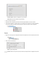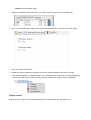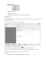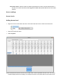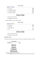
1
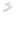
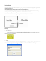
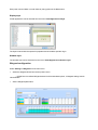
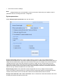
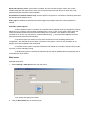
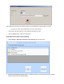
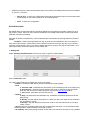
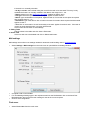
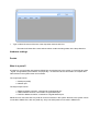
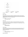
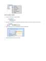
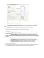
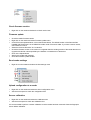
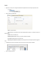
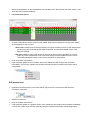
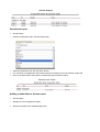
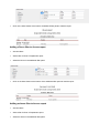
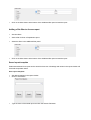
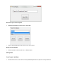
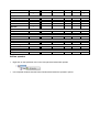
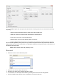
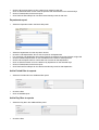
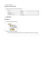
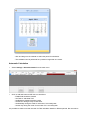
Visual Plus Corporation
http://www.visual-plus.com
PROS Plus Professional
Version 1.0.0
User Manual
02/2013
Copyright © 2012 XPR
Table of Contents
Getting Started 5
Starting 5
Create a Portal 6
Adding a control panel 6
Adding a user 7
Upload users to a controller 8
Manual 9
Program menu 9
Operator log in 9
Display options 9
Wiegand configuration 10
System parameters 11
Web server 12
Automatic Evacuation report printing 13
Scheduled tasks 14
Mail settings 15
Find users 15
Hardware settings 16
Portals 16
What is a portal? 16
Hardware 17
Add a Serial Portal 17
Add a Network portal 18
Search network portals 19
Configure the portal 19
Edit a portal 21
Delete a portal 22
Firmware update 22
Control panels 23
Add a controller 23
Edit a controller 24
Start/stop pooling 27
Upload configuration to a controller 27
Set controller time 27
Upload users database 27
Firmware update 27
Check firmware version 28
Doors 28
Door control 31
Readers 32
Fingerprint readers 33
Add or modify a reader 34
Check firmware version 36
Firmware update 36
Read reader settings 36
Upload configuration to a reader 36
Sensor calibration 36
Inputs 37
Outputs 38
Output control 39
Function cards 40
Access settings 41
Access levels 41
Adding Access level 41
Edit access level 42
Delete Access Level 43
Departments 43
Add a Department 43
Edit a Department 43
Delete a Department 43
Users 44
Add a user 44
Edit a user 45
Delete a user 46
Fingerprints 46
Read me first 47
Enrolling Fingerprints from a reader 47
Enrollment from a desktop Reader 48
Uploading the fingerprints to the Fingerprint readers 49
Deleting Fingerprints 49
Deleting one user from the fingerprint Reader 49
Deleting all users from the fingerprint Reader 49
Deleting user finger templates from the Software 49
Complex upload 50
Reports 50
User list report 51
Access reports 51
Load report window 51
Set time filters 52
User report 52
Unknown ID report 53
Department report 54
Adding a reader filter to Access report 54
Adding a Doors filter to Access report 55
Adding an Areas filter to Access report 55
Adding a Site filter to Access report 56
Saved report template 56
I/O reports 57
Load report window 57
Set time and controllers filters 58
Inputs report 58
Outputs report 58
Doors report 59
HardwareReport 59
Evacuation report 60
Program operators 61
Add an operator 62
Edit an operator 63
Delete an operator 63
Time and Attendance 63
Workgroups 63
Shifts 64
Public holidays 66
All day absences 68
Reports 69
Edit Reports 69
User report 70
Department report 71
Add a Period filter to reports 71
Add a Day filter to reports 71
Add a Event filter to report 72
Calculation 72
Automatic Calculation 73
Manual Punch 74
Function cards 74
Web report server 75
Time filter 75
Access & Attendance report 75
Basic filter 75
User report 76
Department report 76
Additional filter 77
T & A filter 78
Hardware report 79
Reports options 80
Troubleshouting 81
Biometry 81
Glossary 84
Getting Started
This Getting Started Guide will use examples to guide you through the minimum configuration required after
installing the PROS Plus.
This example assumes that the system contains the following elements:
1. Access controller EWSi (2 Reader controller with a built-in CNV1000 TCP/RS485 network converter),
controlling main entry to the building with Reader 1 outside and Reader 2 inside.
2. Both readers should be standard proximity readers with a Wiegand 26 bit interface.
Starting
o Run PROS Plus
Select PROS Plus from the Start>All Programs>XPR>PROS Plus menu or double-click on the
PROS Plus icon on your desktop.
o Login
On the PROS Plus main menu, select Program>Log in. On the login window, select operator and
enter the password (The default setting is Operator name = "Admin" and Password = "admin")
Create a Portal
o Right-click on the Portals item and select Add portal
o Consult your installer for the portal IP address and Port, and fill in the Portal properties window with the
data.
o Click on Add & Exit
o The new portal will be shown below the Portals item
Adding a control panel
o Right-click on the new portal Local CNV1000 item and select Add controller>EWS
o Consult your installer for the controller Serial number and fill in the controller properties window with the
data.
o Click on Save & Exit button
o The new controller and controller peripherals are shown under the portal item.
Adding a user
o Double-click on the Users item
o On the Users window click on New user. The button caption will change to "Save".
o Enter the Name of the user, the user ID (card number), select Unlimited in the Access level drop-down
list box, select General in the Department drop-down list box and select the validity period from-until.
o Click on Save
o The entered user will be added to the user table on the left
Upload users to a controller
o Right-click on controller item and select Reload keys
o Information about the controller update will be added to the event table
Manual
Program menu
Operator log in
PROS Plus starts without an operator logged in. Only event pulling will be running. Logging in allows
changing operator options.
How to log in:
Select Program>Log in in the PROS Plus main menu. On the login window select operator and
enter the password. The default password for the user Administrator is "admin".
How to log off:
In the PROS Plus main menu select Program >Log out.
Display options
Display panels
PROS Plus main area is divided into Hardware management, Users management and Events displaying
panels.
Each panel can be hidden or made visible by using options in the View menu.
Display style
Visual appearance can be selected from the menu View>Appearance>Style
The Style is stored with the operator's properties and is loaded at operator log in.
Shadow style
The shadow style can be selected from the menu View>Appearance>Shadow style
Wiegand configuration
Select Settings > Wiegand from the main menu.
o Select the Wiegand format from the drop-down menu.
- PROS Plus has defined Wiegand 26 and 34 bit as standard options; 3 Wiegand settings remain
user definable.
o Set the Wiegand parameters.
o Click Save to save the settings.
Note:
Wiegand settings are not accessible to common end users. Please ask your installer to set the
parameters and do not change them later. configuration
System parameters
Select Settings>System parameters from the main menu
Access Code length: Defines the number of digits used for a keyed-in code, if the installed hardware
supports Access Code access. This value is valid for all equipment. If entered values for the Access Code are
longer than the selected value, digits will be removed from left to right. For example, if the Access Code was
12345678 and the Access Code was reduced to a length of 5 digits, the new Access Code sent to the
equipment would be 45678. If the length was increased, the necessary number of zero (0) digits would be
added to the left side of the Access Code so that the required length is achieved. If the Access Code has a
value of zero (0), it will be considered as "no Access Code".
Events display control: The events table contains images that can use up a large amount of system
memory and reduce system performance. Therefore when the events table reaches a pre-defined maximum
number of events shown, the row number will be reduced to the latest defined number of events.
Display events with Site code + User card format: If this is checked the events table instead of the User's
ID it will give the Site code and the User code.
Allow web report for users: If this option is enabled, all users can take a report of their own access
activities using the web report server. Users can access the web server with his or her name and a web
password that was entered in Personal Details.
Use default PC network interface only: Use this option if the system is connected to something other than
the default network interface in PC.
Auto Logon: If enabled, the selected user will be logged in at program start if the correct password is
entered.
Automatic update options:
- If this Controller’s option is checked, the controllers will be updated when any changes are made by
PROS Plus. For example, if the Controller properties form is open, a click on the "Save & Exit" button will
invoke the update procedure and send the new settings to the controller. If the update is not possible
(controller is not on-line, not mounted yet, network malfunctioning ...), the event will be added to the event
panel and must be performed manually later.
- If the Users option is checked, for every Save command on forms containing relevant user
configuration, user data will be sent to all the controllers in the system. If some of the controllers do not
respond, the event will added to the event panel.
- If the Date & Time option is checked, PROS Plus will update the controller’s date and time on start
and every 12 hours if already running.
- If the Biometry option is checked, the biometric devices will be updated when the properties form is
closed with the "Save" button.
Web server
Start/Stop web server
o Select Settings > Web Service from the main menu.
- Port: set the web page port number.
o Click the Start web button to start the server .
After starting the web server the program will give you the Application ID and the URL for the web.
- Url: gives you a list of the possible links for access via the internet.
o If the service cannot be started, try with a different web page Port value
o Click the Check button to open the selected link.
Automatic Evacuation report printing
o Select Settings > Automatic Evacuation report printing from the main menu.
o Generate automatic Evacuation report - if enabled, PROS Plus automatically will print Evacuation
report in case of a fire on selected printers.
o Select the printers you want the Evacuation report to be printed ( the listed printers are the one installed
on your PC ) and click
o Save & Test - to save your configuration and to test the Evacuation report. An Evacuation report
should appear on the screen and print on the selected printers.
o Save - to save your configuration.
Scheduled tasks
Scheduled tasks are tasks that will be executed by PROS Plus at regular time periods. Periods can be a
day, week or month. Each hour from when the PROS Plus has started a task routine is performed and all
tasks are executed by schedule.
Each task is performed retroactively. The first tasks that are executed are the missing tasks from previous
periods.
Example: if Task1 should generate each day at 10:00 hour and PROS Plus was not running for 3
days at the first execution of task routine Task1 it will be executed as running 2 days ago, on the second
execution of task routine Task1 (1 hour later) it will be executed as running 1 day ago and then after 1 hour
task routine Task1 will be executed as a normal daily task.
1. Adding task
Select Settings>Scheduled tasks from the main menu to open the Tasks window
Click the Add task button.
The newly created task row will display the columns as follows:
- Enable: If checked the task will be performed otherwise it will be ignored.
- Task:
a. Calculate T&A - calculates T&A data (same as the calculate function in the T&A menu).
b. Send by mail - generate a report and send it by email. In order to be able to send an
email the mail account for sending should be set up in the Mail settings window.
c. Save to file - generate a report and save to file.
- Repeat:
a. Daily– the task will be executed each day. Calculation and reports will be done for the
previous day.
b. Weekly– the task will be executed once a week, the day of the week can be selected in
the "At weekday" column.
c. Monthly – the task will be executed each month on the date selected in the "At day in
month" column.
- At hour: select at what period during the day the task will be executed. If 10 is selected the task
will be executed in a period between 10:00 and 10:59:59.
- At weekday: select a day during the week for the task to be executed. This entry is only available
if the task is on a weekly schedule.
- At day in month: select a date during the month for the task to be executed. This entry is only
available the if task is on monthly schedule. Use dates in the range from 1 - 28.
- Report: select one of the saved report templates. Applies for tasks b and c.
- File type: select the report file format for export. Applies for tasks b and c.
- Mail to: type email address of recipients. Applies to task b, If more than one recipient is required
then separate them by , or ; .
- Destination: type in the field or click on button to browse for location where report should be saved.
Applies to task c.
- Test: Click on this button to check functionality of the task. Applies for tasks b and c. If the task is
correct an email should be sent or a report will be saved.
Click on Save & Exit button to save settings.
2. Editing Tasks
Edit the values in the table and click Save & Exit button.
3. Delete Task
Click on a task row to be deleted and click on Delete task button.
Mail settings
Mail settings are email account settings needed for automatic email sending used in Scheduled tasks.
o Select Settings > Mail settings from the main menu to open Mail Server Settings window.
o Complete email account details.
o For Test Message Settings type in the recipients email into the TO field then click on the Send Test
o
Message button and check if the test message is sent to the correct recipient.
Click on Save configuration.
Find users
o Select Find > User from the main menu.
o Type or select the name of the user in the drop-down list and click Find.
- The search will show all the users whose names contain the string written in the drop-down box.
Hardware settings
Portals
What is a portal?
A Portal is a communication link between PROS Plus and the devices in the system. A Portal has two parts
- logical, recognizable by the software, and physically – an electronic device connected to a computer and
other devices in the system known as converters.
The Logical part can be:
1. Serial port (COM)
2. Network port
The Physical part can be:
1. RS232 to RS485 converter, connected to a logical Serial port
2. USB to RS485 converter, connected to a logical Serial port
3. TCP/IP to RS485 converter, connected to a logical Network port
PROS Plus can use more than one portal to connect to devices in the system. Devices in the system can be
connected to PROS Plus, with one portal only. Only one Serial portal can be used in PROS Plus.
Hardware
RS232 to RS485
This converter is connected to the PC’s COM port. It is powered by the COM port so it does not require a
separate power supply, except in the case that the PC’s COM port does not have all its signal outputs used
for power (DTR, RTS) or enough power to drive the converter. This converter does not require any drivers to be
installed if the COM port on the PC side is installed properly.
Requirements:
- Available PC COM port (RS232)
- RS232 to RS485 converter
USB to RS485
This converter is connected to the PC’s USB port. It is powered by the USB port so it does not require a
separate power supply, except in the case that the PC’s USB port does not have enough power to drive a
converter. This converter needs the suitable driver to be installed before use. If installed using the PC’s driver
manager it will appear as a COM port.
Requirements:
- Available PC USB port
- USB to RS485 converter
TCP/IP to RS485
This converter is connected to the PC over a local network or directly with a network patch cable. It uses an
external power supply. This converter does not need any drivers to be installed. Some Access control
equipment may have a built-in TCP converter used by the same device and other devices in the system to
communicate with PROS Plus.
Requirements:
- Access to local network or PC network card.
- TCP/IP to RS485 converter
Add a Serial Portal
o Right-click on the Portals item and select "Add portal"
o Enter the portal name
o Make sure that the Network communication option is not checked
o Select the COM port from the Serial port drop-down list
o Click on Add & Exit
o The New portal is shown below the Portals item with a given name and a picture of the serial portal
Add a Network portal
o Right-click on the Portals item and select "Add portal"
o Check the Network communication option
o Consult your installer for the portal's IP address and Port, and fill in the Portal properties window with the
data.
o Click on Add & Exit
o The new portal is shown bellow the Portals item with a given name and a picture of the network portal
Search network portals
This procedure is valid only if you have a CNV1000 TCP convertor or device with built-in CNV1000
o Right-click on the Portals icon and select the Search network portals
o On the Search portal window select the port to search (default is 8000)
o Click on the Search button and wait
o If any portal is found, it will be displayed in the table
o If the Portal does not exist in PROS Plus, click on the Add column button in the portal row.
o The Portal will be added to your collection of Portals with the same name as the found device IP
Configure the portal
o Right-click on the Portals icon and select the Search network portals
o On the Search portal window select the port to search (the default is 8000)
o Click on the Search button and wait
o If any portal is found, it will be displayed in the table
o Enter an 8 digit device password (factory default is 00000000)
o Find a row with a portal to configure and click on the appropriate Setup button
o The setup portal window is shown with the portal settings. If the values are empty, reading settings from
CNV1000 will not be possible
o Enter new settings:
- IP: IP address of device
- Setup port: Network port for search and setup. Changing is not recommended
- Password: Password for access to read and change the settings of the CNV1000. It is
recommended to change the default password and use it for all converters in the system.
- Mask: Enter the device subnet mask
- Gateway: Default gateway
- MAC: Physical address of the device. Changing is not recommended
- DHCP Enable: Enable the DHCP client
- DNS: Address of the DNS server
- Data port: Port used for communication between PROS Plus and devices behind the converter
- Dedicated client: To forbid unauthorized access to devices connected to the portal from another
system, select one of the following options
a. Disabled - no source security checking
b. MAC only
- the source MAC address must be equal to the Dedicated MAC value
c. IP only– the source IP address must be equal to the Dedicated IP value
d. IP or MAC - at least one of the conditions from point b and c must be true
e. IP and MAC - both b and c conditions must be true
- Enable web interface: enable or disable the CNV1000 web interface for configuration
- Web port: Web interface port
- Version: Read-only field displaying the firmware version of the converter
o Click on Send settings to configure the device, wait for the result message
Edit a portal
o Right-click on portal and select Properties
o Change the settings on the properties window
o Click on the Save & Exit button
Delete a portal
The Portal can be deleted only if there is no device added to it
o Right-click on the portal and select the Delete menu
o Confirm deletion
Firmware update
A Firmware update can only be done to a CNV1000 standalone or embedded converter
o Check the portal firmware version by using the Configure CNV1000procedure
o Right-click on the portal to be updated and select the Firmware update menu
o On the Firmware update window, click the Browse button. The default location of the firmware files
installed with PROS Plus is in the PROS Plus folder under "Firmware" folder. If you have a newer version,
use browse to locate it.
o Select the firmware file with a "xhc" extension
o Check the firmware version. If the version is not greater than the existing version of the CNV1000 then do
not upgrade with this file, unless specified by the installer or manufacturer of this device.
o Click on the Upload button
o Wait for the "Update End Message"
o Close the Firmware update window
Control panels
Add a controller
o Right-click on a portal connected to the controller and select Add controller>EWS
o Enter Name and Serial number of the controller. The Serial number is provided on the controller’s board.
o Click on the Save and Exit button
o The New controller and the controller peripherals are shown under the portal item
o In order to see if EWS is online and communicating with the PC, right click on the Controller and select
“Check Version” from the controller drop-down menu. In the event panel it will be indicated if the controller
is on line or not. If the Serial Number does not match, the controller will not go on line. If there is no
communication, the controller name will have a red background color in the tree view.
Edit a controller
o Right-click on the controller and select the Properties menu
o On the controller properties window select the Advanced tab
- Recycle events: When option is checked then the EWS will delete the events from its memory
when it is full.
- Enable communication: If the Enable communication is not checked,when PROS Plus is started,
the event pooling from the controller will not run until it is started manually via the controller menu option
"Start pooling"
- Mantrap doors: If the mantrap option is used,check the doors to be used in the mantrap
o Select APB tab (anti-passback)
o Configure two Anti-passback reader groups if required
- Anti-passback group readers: select the readers in the APB group
- Select IN reader: Select the readers allowing entry to the protected area in the APB group. The
selected readers must also be selected in the Anti-passback group readers.
- Timeout: Set the time period, in minutes, required to allow the user to enter the protected area
again without exiting the same area. If this option is not required, enter 0.
- Reset at: The time of the day for the APB options to be reset. All users will be considered as out of
the protected area.
- Reset APB by Inputs: Assign Inputs to reset APB.
- Reset APB on power failure:APB status will be reset whenever the EWS controller is powered
down and then powered back up again (power switched back ON).
o Select Time Zones tab.
- Set the time zone per controller.
Time zones are time periods with validity defined by a start and stop time in a day. The total number
of time zones is 24. Planning the time zones should be done carefully because the same zones are used for
access levels, doors, readers and input and output configuration. It is recommended to plan these steps
carefully before starting system configuration.
- Time zone name: enter the time zone name.
- Begin: enter the time zone start time of the day.
- End: enter the time zone end time of the day.
- Hol: set if the time zone is valid for holidays.
- Mon-Sun: set the weekday validity.
o Select Holidays tab.
- Set Holidays per controller.
- Holiday column: enter the holiday name.
- Repeat column: check to make the holiday valid annually.
- Day column: enter the holiday date or click on the right side and select the date in the new
calendar window.
o Click on the Save & Exit button.
o If the Automatic update for controller’s option is set, PROS Plus will configure the controller immediately.
If it is not set, update the controller manually via the controller menu option "Send configuration"
Start/stop pooling
o Right-click on the controller and select the Start or Stop pooling menu
This setting will be valid until PROS Plus is closed.
Upload configuration to a controller
o Right-click on the controller and select the Send configuration menu
o See the events panel to check the configuration flow
Set controller time
o Right-click on the controller and select the Set time menu
The Time and Date value from the PC will be sent to the controller. Check the PC’s time and date
accuracy before using this command.
Upload users database
o Right-click on the controller and select the Reload keys menu
This command will erase the controller user database and upload users from the PC database
Firmware update
o Check the controller firmware version
o Right-click on the controller and select the Firmware update menu
o On the Firmware update window, click the Browse button. The default location of the firmware files
installed with PROS Plus is in the PROS Plus folder under "Firmware" folder. If you have a newer version,
use browse to locate it.
o Select the firmware file with an "xhc" extension.
o Check the firmware version. If the version is not greater than the existing version of the controller then do
not upgrade with this file unless specified by the installer or manufacturer of this device.
o Click on the Upload button
o Wait for the "Update End Message"
o Close the Firmware update window
Check firmware version
o Right-click on the controller and select the Check version menu
The version is displayed in the events panel
Doors
o Expand the controller item to see the doors
o Right-click on the door to be configured and select the Properties item from the door drop-down menu
o Set the values in the Door Basic tab
- Name: Enter Door Name
- Enabled by time zones: enable the settings in the Time zones tab for the Door.
- Type:Select door type. This option will only change the door image/icon in the list underneath the
name of the EWS controller, but no changes will be done in system behaviour.
- Lock release time: The lock release time can have a value between 1 to 255 seconds. If toggle
operation is needed, enter 0.
- Door has not been closed timer: The time allowed for the door to be left open after authorized
access and before the Door open too long event (alarm) is invoked. If there is no limit, enter 0.
- Door open too long time: The time allowed for the door to be open after authorized access and
before the Door open too long event (alarm) is invoked. If there is no limit, enter 0.
- Enable door sensor: can be set to enabled or disabled.
- Door sensor type: can be set to Normally Close (NC) or Normally Open (NO), depending on the
type of sensor (state at closed door).
- Push button type: can be set to Normally Close (NC) or Normally Open (NO).
- Push button enabled: allows the door to be opened using the push button.
- Enabled by time zones: enable the settings in the Time zones tab for the Push button.
o Set the values in the Auxiliaries tab
- OUTPUTS: Select the door event(s) that will activate the relay outputs (except door relays; door
relays follow the authorization rule)
- INPUTS: Select if any input should disable the door
o Select the Time zones tab and check the time zones during which the door lock should be released
o Select the Alarms tab
- Assign relays for alarms listed
- After alarm, deactivate Output: the behaviour of the ouput after the alarm has triggered.
When door is closed: the output will be deactivated when the door is closed.
By Output timeout setting: Output will behave as configured.
o Click on the Save & Exit button
o Repeat the door configuration procedure on the other doors driven by the same controller
o If the Automatic update for controllers option is set, PROS Plus will configure the controller immediately,
if it is not set, update the controller manually with the controller menu option "Send configuration"
Door control
o Right-click on the door to control and select the control item from the door drop-down menu
- Open: Acts as legal access to the door, door behavior is the same as normal access
- Lock: Locks the door so that it can't be opened by users
- Unlock: Cancels the Lock command
Readers
o Expand the Door item to view the readers
o Right-click on the reader to be configured and select the Properties item from the reader drop-down menu
o Set the values in the Basic tab
- Name: Enter the Reader's Name
- Type: Select the Reader's Type
- Entry mode:This selection is optional and is visible if reader supports different modes of entry. E.g.
if using an LCSP card/Access Code reader then four modes of entry are available.
- Door: Select which controller door the reader is attached to.
- Wiegand type: Select the Wiegand type of the Reader
- Enable access by time zones: enables the settings in the Free Access Time Zones tab.
- Bypass Antipassback: if this is checked antipassback will not be valid for this reader.
- Exit from: set the area which is exited.
- Entry to: set the area which is entered.
- Antipassback reset time: set the duration time of antipassback.
- Free access 24/7: grant all users 24/7 utilisation.
- In the event of (number) illegal attempts disable for (number) minutes: set the number of
illegal attempts and the time of disabling the reader.
- Required number of valid users for access: Number of different users that must be registered at
the reader to grant access.
o Select the Free Access Time Zones.
- Apply the time zones for the reader.
o Click on the Save & Exit button
o Repeat the reader configuration procedure on the other readers driven by the same controller
o If the Automatic update for controllers option is set, PROS Plus will configure the controller immediately,
if it is not set, update the controller manually using the controller menu option "Send configuration"
Fingerprint readers
If fingerprint readers are used, additional reader menu items are available
Add or modify a reader
o Expand the Door item to view the readers
o Right-click on the reader to be configured and select the Properties item from the reader drop-down menu
o Set the reader type to one of the fingerprint models in the Basic tab
o Select the Biometric tab and set the values
- Serial: Fingerprint Reader Serial Number
- Sound level: Sound level of the device
- Finger Acceptance Flexibility: Acceptedtolerance. The recommended value is “Automatic
Secure”.
- Sensitivity: Bio-sensor sensitivity, the recommended value is 7, most sensitive.
o If devices have a keypad (BioXr, BioXrC), further settings will be available:
- Entry mode:
“Finger” (the keypad is inactive)
“Finger or keypad” (The Fingerprint Reader will be configured to accept either PIN
Codes or fingers)
“Finger and Keypad” (The Fingerprint Reader will be configured for double security,
requiring a PIN Code and a corresponding finger. Only the right combination will send the user Wiegand
to EWS)
- Send This ID for:
Unknown Finger sends the desired Wiegand when an unknown finger is applied.
Unknown PIN sends the desired Wiegand when an unknown Pin Code is applied.
Button “A” Pressed sends the desired Wiegand when button “A” is pressed.
Button “B” Pressed sends the desired Wiegand when button “B” is pressed.
o Click on the Save & Exit button
o If the Automatic update for biometry option is set, PROS Plus will configure the reader immediately, if it
is not set, update the reader manually using the reader menu option "Send configuration"
Check firmware version
o Right-click on the reader and select the Check version item
Firmware update
o Check the reader firmware version
o Right-click on the reader and select Firmware update menu
o On the Firmware update window, click on the Browse button. The default location of the firmware files
o
o
o
o
o
installed with PROS Plus is in the PROS Plus folder under "Firmware" folder. If you have a newer version,
use browse to locate it.
Select the firmware file with a "xhc" extension
Check the firmware version. If the version is not greater than the existing version of the reader then do not
upgrade with this file unless specified by the Installer or manufacturer of the device.
Click on the Upload button
Wait for the update end message
Close the Firmware update window
Read reader settings
o Right-click on the reader and select the Get settings menu
Upload configuration to a reader
o Right-click on the reader and select the Send configuration menu
o See the events panel to check the configuration flow
Sensor calibration
o Right-click on the reader and select the Calibrate menu
o See the events panel to check the Calibration flow
It is recommended to perform a sensor calibration once the reader has been mounted. Clean the fingerprint
sensor before calibration.
Inputs
o Right-click on the input to configure and select the Properties item from the input drop-down menu
o Set the values in the Basic tab
- Name: Type Input Name
- Type: Select the normal state of the contact energizing the input (NO = no voltage on input, NC =
input powered)
- Enable: Check to enable input
- Enabled by Time zones: Check if you need to enable time periods
- Fire alarm: Dedicate input to Fire alarm input
- Required pulse duration to activate: Set the length of time of the signal required to trigger the
input.
o If Enabled (Time zones are checked), set the time zones for which the input is enabled
o Set the Auxiliaries options
- Activate outputs: Outputs to be triggered on input activation
- Open doors: Doors to be released on input activation
o Click on the Save & Exit button
o Repeat the reader configuration procedure for the other inputs available on the same controller
o If the Automatic update for controllers option is set, PROS Plus will configure the controller immediately,
if it is not set, update the controller manually using the controller menu option "Send configuration"
Outputs
o Right-click on the output to be configured and select the Properties item from the output drop-down menu
o Set the values in the Basic tab
- Name: Type the Output Name
- ON time: Select how long the output relay should stay energized. Enter 0 to toggle the relay state
on event.
- Enable: Check to enable output
o Select the Activated at Time zones tab if you need to use the output as a time activated relay
o Click on the Auxiliaries tab to select if the output relay should follow the door sensors or door relays
o Click on the Save & Exit button
o Repeat the output configuration procedure on the other outputs available on the same controller
o If the Automatic update for controllers option is set, PROS Plus will configure the controller immediately,
if it is not set, update the controller manually using the controller menu option "Send configuration"
Output control
Right-click on the output to be controlled and select the control item from the drop-down menu
- Enable: Enables output
- Disable: Disables output
- Activate: Output responds as programmed to behave when it is ON
Function cards
Function cards are special type of users that can invoke some action from the access controller. These cards
cannot be used for access.
Double-click on the Function cards icon in the Users Panel.
Function cards can be managed in a same way as users.
Function cards will be valid on EWS controllers having readers in selected Access levels.
The action of the function cards will be conducted only on EWS controllers where the card is presented.
A function card can be used as an access Access Code or Finger print.
Functions:
APB reset: Controller will reset APB status of all users to "nowhere".
Reset door alarm: If the door alarm is activated, presenting the function card will reset the alarm. If
the door is not closed, the alarm will be triggered ON again after periods defined in the door alarm
settings.
Access settings
Access levels
Adding Access level
o Right-click on the Access level main item in the Users Panel and click on "Add new Access level"
o Enter the Access level name
o For Lite option:
Check the Allowed access time zones for each reader. Each column represents one time zone. The column
headers display the time zone setting. For example, as shown in the picture above, the Access level is
defined by authorization on the readers Main entry and Main exit in the first time zone (from 9:00 to 17:00
each day of the week and holidays).
o For professional option:
o Check the Allowed access time zones for each reader. Each column represents one time zone. Setting
access depends on the row color.
- Green color: Reader is set for access without a time zone schedule. Access on this reader will be
granted if any time zone field for this reader is checked. Access will be denied if none of the
fields are checked.
- Red color: Reader is set to grant access by time zones. Access will be granted if the event is
within any of the checked time zones. Time zone settings for each reader/Time zone can be
checked by holding the mouse cursor over the checkbox as shown above.
o Click on the Save & Exit button
o If the Automatic update for the controllers option is set, PROS Plus will configure the controllers
immediately, if it is not set, update each controller manually using the controller menu option "Send
configuration"
Edit access level
o Expand the access level item in the Users Panel, right-click on the Access level and select the
"Properties" menu item
o Edit the Access level
o Click on the Save & Exit button
o If the Automatic update for controllers option is set, PROS Plus will configure the controllers immediately,
if it is not set, update each controller manually using the controller menu option "Send configuration"
Delete Access Level
o Expand the Access Level item in the Users Panel, right-click on the Access level and select the "Delete"
menu item. The Access Level cannot be deleted if any users are assigned to it.
Departments
Add a Department
o Right-click on the Departments item in the Users Panel and click on "Add new"
o Enter the Department name and click on the save & Exit button
Edit a Department
o Expand the Department item in the Users Panel, right-click on the Department and select the "Edit"
menu item
o Edit the Department name
o Click on the Save & Exit button
Delete a Department
o Expand the Department item in the Users Panel, right-click on the department and select the
"Delete" menu item.
o Default department "General" can not be deleted.
Users
Double-click on the Users item in the Users Panel to open the Users window
Add a user
o Click on the New User button
- Enter the Name of the User
- Enter theUser ID (card number). If there are two numbers on the card with values less than 65536
then use the Site code and the User code box.
- Enter Access Code if in the system will be used devices with keypads
- Select the Access level from the Access level drop-down list box
- Select the Department from the drop-down list box
- Select Workgroup
- Select the from-until validity period
- Click on the Set image button and then browse for the User's image
- If Apply Anti-pass policy option is checked, user must behave by APB settings of the readers,
otherwise user will have no APB restriction.
- Single entry user:A User will have one-time entry an all readers defined by user access level. If the
user has used his/her one-time entry, on the next upload of the user in the EWS controller, one-time
entry will be renewed.
o Fill Personal details of the user if required in the Personal details tabs.
o If the User should activate some outputs (not door relays), click on the Output control tab to select
outputs
o Click on Save
o The entered User is added to the user table on the left side
o If the Automatic update for users option is set, PROS Plus will upload the changes immediately, if it is
not set, update each controller manually using the controller menu option Reload keys (Reload Users)
after editing the users is completed and the users window is closed
Edit a user
o Select the User to be modified in the users table on the left side of the Users window
o Modify the user data (including the name if required)
o Click on the Save button
o If the Automatic update for users option is set, PROS Plus will upload the changes immediately, if it is
not set, update each controller manually using the controller menu option Reload keys (Reload Users)
after editing the users is completed and the users window is closed
Delete a user
Warning!
Deleting a user erases the user from database. If you need to keep an activity record of the user,
you can change the access level to "No access" instead of deleting the user, or generate the
necessary reports and save them to a file (PDF is recommended), before deleting the user.
o Select the user to be deleted in the users table on the left side of the Users window
o Click on the Delete button
o If the Automatic update for users option is set, PROS Plus will upload the changes immediately, if it is
not set, update each controller manually using the controller menu option Reload keys (Reload Users)
after editing the users is completed and the users window is closed
Fingerprints
Read me first
Selecting a finger for fingerprint enrollment
At least two fingerprints should be enrolled for each user in case of any abnormal situation like having an
injured finger or carrying an object by hand.
In case of low recognition, the user can register the same fingerprint twice to increase the recognition rate.
It is recommended to use the index or middle finger. If you choose another finger, the recognition rate may be
decreased because it tends to be more difficult to place the finger in the center of the sensor area.
Caution while registering a fingerprint
The initial fingerprint registration is important.
Because the recognition process compares the scanned fingerprint with the registered one, an abnormally
registered fingerprint can cause a failure.
1. Put the center of your fingerprint on the middle of the sensor
2. If you have a cut on your finger or your fingerprint is not clear enough, retry with another finger
3. When the fingerprint recognition is in progress, do not move your fingerprint
Enrolling Fingerprints from a reader
o Select the User in the User Column, NOT the Check Box (the Check Box is used for sending the
fingerprints) and the User Name cell will turn blue,then select the Biometry tab.
o Select the Fingerprint reader from where the enrollment will be done.
o Right click on the fingertip and select “Enroll”.
o In the next 15 sec. present the finger on the selected reader and the finger tip will turn red, with the
percentage of successful enrollment shown next to the fingertip.
o Repeat the procedure for the other fingers (as required)
Note: If more fingerprints are added for one user, all fingers will send the same Wiegand Code to the
controller.
Enrollment from a desktop Reader
Install the Desktop Reader (BioE) using the drivers located on the CD provided with the Fingerprint Reader. It
is installed in the same way as a USB Device. When the desktop reader has been installed it will
automatically appear in the Software.
o Select the User in the User Column, NOT the Check Box (the Check Box is used for sending the
fingerprints) and the User Name cell will turn blue.
o Select the desktop reader from where the enrollment will be done.
o Right click on the fingertip and select “Enroll”.
o In the next 15 sec. present the finger on the selected reader and the finger tip will turn red, with the
percentage of successful enrollment shown next to the fingertip.
o Repeat the procedure for the other fingers (if needed)
Note: If more fingerprints are added for one user, all fingers will send the same Wiegand Code to the
controller.
Uploading the fingerprints to the Fingerprint readers
o Select the Users whose fingers templates will be sent to the reader, by clicking on the checkbox of the
user
o Select the Fingerprint Reader to where the Users data should be sent and click on “Upload selected
users to reader”
o As each user is being sent, the checkbox will uncheck indicating that the user has been successfully
sent. At the same time the Amber LED of the Fingerprint Reader will blink. Note: The average time for
transferring one finger template is 0.8 sec.
Note: If there were any PIN Codes available, they will also have been sent.
Deleting Fingerprints
In General, after transferring, the fingerprints are stored in the Fingerprint Reader and in the Software.
Deleting can be done only in the software, only in the readers or from both places.
Deleting one user from the fingerprint Reader
o Select the user’s checkbox
o Select the Reader from where the users should be deleted and click on “Delete selected users from
selected readers”. The user is then deleted from the reader, but the fingerprints remain in the software’s
database. They can be sent once again without the need of re-enrollment.
Deleting all users from the fingerprint Reader
o Select the Reader from where the users should be deleted and click “Erase Reader Database”.
Deleting user finger templates from the Software
o Select the User.
o Go to the fingertip that needs to be deleted, right click and select ”Delete” for one finger or “Delete All” for
all fingers of the User. With this procedure the User’s fingerprints are deleted from the software, but they
remain present in the reader.
Complex upload
Complex user upload is used to send multiple user selections to many readers.
o Click on Upload table in themain menu
o Use the mouse click to select the combination you need or use right-click to check or clear an entire row
or column
o Select Upload Users to readers or Delete Users from readers in the right-click menu
o As the upload progresses, the check boxes are cleared showing that the appropriate combination was
successfully done
o When the upload is completed, if there are still some checked items, repeat the upload command
Reports
To generate reports expand the Reports item in the User panel.
All reports are shown on the report form with following buttons:
Export - save report to disk or send it to mail recipient in various file formats (PDF, Excel, Text…)
Print - print report
Navigation - to view the First page, Previous page, Next page, Last page
Find - search for specific text in the report
User list report
o Double-click on the ID item in the expanded Reports item
o Wait for the report to be generated as shown
Access reports
Load report window
o Double-click on the Access item in the expanded Reports item to open the Access report window
Set time filters
o Select time period
- If Repeat daily is checked, reports will be generated for the selected time range of the day, every
day in the selected days range
User report
o Set time filters
o Select the User tab in the Basic filter panel
o Select the user name from the drop-down list box
o For more than one user report select users by checking them at check boxes at right side
o For a report of all users, check the "All users" item
o Click on the Show button at the bottom of the Basic filter panel to load the report
Unknown ID report
o Set time filters
o Select the User tab in the Basic filter panel
o Check "Unknown ID"
o Click on the Show button at the bottom of Basic filter panel to load the report
Department report
o Set time filters
o Select the Department tab in the Basic filter panel
o Select the department from the drop-down list box
o For more than one department report select users by checking them at check boxes at right side
o Click on the Show button at the bottom of Basic filter panel to load the report
Adding a reader filter to Access report
o Set time filters
o Set filter for User or Department report
o Select the Readers in the additional filter panel
o Click on the Show button at the bottom of Additional filter panel to load the report
Adding a Doors filter to Access report
o Set time filters
o Set the filter for User or Department report
o Select the Doors in the additional filter panel
o Click on the Show button at the bottom of the Additional filter panel to load the report
Adding an Areas filter to Access report
o Set time filters.
o Set the filter for User or Department report.
o Select the Areas in the additional filter panel.
o Click on the Show button at the bottom of the Additional filter panel to load the report.
Adding a Site filter to Access report
o Set time filters.
o Set the filter for User or Department report.
o Select the Sites in the additional filter panel.
o Click on the Show button at the bottom of the Additional filter panel to load the report.
Saved report template
Parameters selected for a report can be saved for future use. All settings and values in the report window will
be saved except date values.
Save report template
o Set desired settings in the report window
o Click on Save button
1.
Type the name of the saved report and click the Save & Exit button.
Generate report from template
o Select the template and click on the Load button.
1.
Set the desired date period and click on the Show button.
Delete saved template
1.
Select template to delete and click on Delete button.
I/O reports
Load report window
o Double-click on the Access item in the expanded Reports item to open the IO report window
Set time and controllers filters
o Select days and time period
- If Repeat daily is checked, reports will be generated for the selected time range of the day, every
day in the selected days range
o Select controller in the Controller table
Inputs report
o Set time and controller filters
o Select the Inputs in the additional filter panel
o Click on the Show button load report
Outputs report
o Set time and controller filters
o Select the outputs in the additional filter panel
o Click on the Show button load report
Doors report
o Set time and controller filters
o Select the Doors in the additional filter panel
o Click on the Show button load report
HardwareReport
o Double-click on the Access item in the expanded Reports item to open the Hardware report window
o Select days and time period
- If Repeat daily is checked, reports will be generated for the selected time range of the day, every
day in the selected days range
o Select controller in the Controller table
o Click on the Show button load report
Evacuation report
o Double-click on the Evacuation report item to open Evacuation Report window
o Select a site and click the Show button
- The report will show a list of users according to the last event in the site. All users that have any
kind of access event within the selected site will be listed by the last event.
- If for example an evacuation report is to be made on a certain site but a user's last activity is
reported from a different site, the user will not be listed in the evacuation report.
Program operators
Operator options
Program options
Hardware
User
Operator
configuration management management
Report
view
Program
Access
system
online
control
Main menu
System parameters
o
o
Panels view settings
Upload table
o
Portals menu
Add portal
Search portals
o
o
Portal menu
All options
o
Controller menu
Modify properties
o
Start pulling
o
o
Stop pulling
Configure controller
Set controller time
o
o
Reload keys
Delete controller
Firmware update
Check version online
Read settings from
controller
o
o
o
o
o
o
o
o
o
o
Reader menu
Modify properties
Enable reader
Disable reader
Check version online
Firmware update
Read settings from
reader
Configure reader
Calibrate sensor
o
o
o
o
o
o
o
o
o
o
o
o
o
o
o
Input menu
Modify properties
o
Door menu
Modify properties
Open door
o
o
o
Lock door
Unlock door
o
o
o
o
o
o
o
o
o
o
o
Output menu
Modify properties
Enable
Disable
Activate
Operators
All options
o
Access levels
All options
o
Departments
All options
o
User management
All options
o
Reports
All options
o
Add an operator
o Right-click on the Operators menu in the User panel and select Add operator
o In the Operator window enter the Name, Password and select the operator’s options
o Click on the Add & Exit button
Edit an operator
o Right-click on operator and select Properties menu
o Edit the operator properties in the operator window and click on the Add & Exit button
Delete an operator
o Right-click on the operator and select the Delete menu
Time and Attendance
Workgroups
A workgroup is a set of employees that work the same shifts and are registered on the same readers. In any
one day, the members of a workgroup do not have to work the same shift, but in any shift defined for the
workgroup..
o Right-click on the Workgroup item and select Add Workgroup
o Enter the name of the workgroup and select the Entry and Exit readers that this workgroup will use.
- It is recommended that different readers be used for registration of Entry and Exit.
- If the same readers are used for registration of Entry and Exit, the readers have to be checked for
Enter, and none to be checked for Exit. In this case every following event will be treated as opposite to the
previous (if the user has entered, the next registration on the reader will be treated as Exit).
o Click Save & Exit.
o You can edit the workgroup later by right-clicking on the created workgroup and then selecting
Properties.
Shifts
o To create a shift for a specific workgroup, right-click on it and select Add shift.
o Set the parameters for the shift.
- Name: Set the name (number) of the shift.
- Accept registration after: after how long registration of personnel will be treated as the same shift.
- Shift start: time when the shift starts.
- Allow late until: permitted delay. A delay within that time limit will not be shown in the reports and
working time will be estimated as if the person came on time.
- Slide shift if allowed late: if the person is no later than the time defined in "Allow late until", the
person has to stay after the official end of the shift for the same length of time by which he was late,
otherwise the missing period will be treated in the reports as if the person was out.
- Refuse registration after: registration for the beginning of working hours will not be accepted in this
shift. The software will search to see if this registration matches other shifts defined for this workgroup.
- Break accepted from: at which time the person may take a break.
- Break refused after: until when the person may report exiting for a break.
- Break leave time: allowed break time.
- Early leave allowed from: at which time the person may report end of shift without it being treated as
an early leave in the reports.
- Shift end: end of the shift.
- Overtime if after: shows the time after which working hours are counted as overtime hours. If the
person stays later then this time, the time from the end of the shift to the moment he checks out will be
counted as overtime work. If the person leaves before this time the report will show the difference between the
end of the shift and his exit as "staying late".
- Overtime limit time: the person must not stay overtime after this time. If they report the end of shift
after this time, the overtime work will be calculated from the end of the shift to the overtime limit time.
- Treat break time as work: if this option is checked the break time will be added to working hours..
- Treat unused break as overtime:When this option is checked if the person don't leave for break then
the break time will be counted as overtime work.
- Treat "Missing In Event" period as Missing: the software calculates periods between two events Entry and Exit. There are some times when the person may "jump" one event, so there are cases when the
person has exited twice without entering. The period between those two events in the reports can be shown
as a period when the person was not at work (missing) or as a period for which registration of entry is missing
depending on the settings of this option.
- Treat "Missing Out Event" period as Missing: the software calculates periods between two events Entry and Exit. There are some times when the person may "jump" one event, so there are cases when the
person has entered twice without exiting. The period between those two events in the reports can be shown
as a period when the person was not at work (missing) or as a period for which registration of entry is missing
depending on the settings of this option.
- Master report settings: A user can be marked as being absent or working half day based on the
values set in these fields.
- Allowed days: days for which the shift is valid.
o Click Save & Exit
o You can edit the shift later by right-clicking on it and select Properties.
Public holidays
The holiday settings for working hours are separate from the holiday settings for the controllers and they don't
influence access control.
o Double-click on the holiday item to open the holiday window.
o Set the holiday dates.
o Set a holiday.
- First click on a day to select it.
- Check the workgroups for which this holiday is applicable and click on Save holiday.
- The holiday dates will appear highlighted in the calendar.
o Close the holiday window.
o The procedure for deleting holiday is the same.
All day absences
o Double-click on the All day absences item to open the window.
o Select the month you want to see/edit from the list and then click on the Load month button.
A list of all users will be shown along with their absences (if they have any).
1.
Every absence is associated with a specific colour as shown below.
2. To add an absence to a specific user
- First click on the date you want to mark (if you want to mark more dates, click and drag the mouse
over those dates).
- Then click on the colour (absence) you need (for example for Sick - click on the Red coloured box
named Sick).
o To delete an absence from a specific user
- First click on the date you want to mark (if you want to mark more dates, click and drag the mouse
over those dates)
- click on the Delete button.
o To delete ALL absences for all users from the selected month
-click on the Clear button.
o If you want to save the changes you've made - click on the Save month button otherwise click on Cancel.
o If you want weekend days to be marked/not marked when setting absences - check/uncheck the
boxes respectively, see below.
o In order for the absences to appear in the reports, a calculation must be done
- manual calculation - Calculate item from the T&A menu
-Automatic calculation - if set in Settings > T&A from the main menu (the calculation will be made
within the hour set inAutomatic Calculation).
Reports
The reports for working hours give estimated cumulative working times for events up until the moment when
the last calculation for the working time was made for the corresponding month. In the event that there new
events or parameter changes for the working hours (workgroups, shifts, holidays) were made since the last
calculation, before generating reports it is necessary to perform a working hour calculation.
o Double-click on the Reports item under T&A to open the T&A reports window.
Edit Reports
o Set the parameters for T&A reports.
- Detailed report: this report gives the total number of working hours for one month and for each day
separately.
- Short report: gives the total number of working hours for a whole month.
- Absences: Gives a list of persons that were absent in selected period.
- Events: Show the events for the selected period
- Manual events: Shows a list of manually added T&A events.
- First/Last Event Report: this report is not included in the calculation of working hours. It gives the
first and the last registration of the person on any reader in the system for each day and the time difference
between these two events. The report does not calculate the difference if the person works a shift which ends
the following day (night shift).
-Master report: Shows a short daily summary report.
User report
o Select the User tab in the Basic filter panel.
o
o
o
o
Select the user from the drop-down list box.
Check the "All users" item to view a report for all users.
For more than one user report select users by checking them at check boxes at right side
Click the Detailed report button to view a detailed list of events for that user.
o
o
o
o
Click the Short report button to view a basic list of events for that user.
Click on Absences button for list of the the persons that were absent on the selected days
Click on Events button for the event report
Click First/Last Event Report to view the first and last day event for that user.
Department report
o Select the Department tab in the Basic filter panel.
o
o
o
o
o
o
o
o
Select the department from the drop-down list box.
Check the "All Departments" item to view a report for all departments.
For more than one department report select users by checking them at check boxes at right side
Click the Detailed Report button to view a detailed list of events for that department.
Click the Short Report button to view a basic list of events for that department.
Click on Absences button to list the absence by department on the selected days
Click on Events button for the event report
Click First/Last Event Report to view the first and last day event for that department.
Add a Period filter to reports
o Select the Periods tab in the Additional filter panel.
o Check the filter.
o Click on Detailed report.
Add a Day filter to reports
o Select the Day tab in the Additional filter panel.
o Check the filter.
o Click on Short report.
Add a Event filter to report
o Select the Events tab in the Additional filter panel
o Check the filter
o Click on Events
Calculation
o Double-click on the Calculate item.
o Select a period and click calculate.
- This operation calculates working hours based on the registration of a person on the readers.
- Click and drag over the calendar to select the period for calculation.
- The calculation can be performed for a period no longer than one month.
Automatic Calculation
o Select Settings > Scheduled tasks from the main menu.
o Click on Add task button and fill new row as follows:
- Enable field should be checked
- Set Task to "Calculate T&A"
- Set Repeat to desired execution period
- Set the hour during the day for execution.
- Set Weekday during the week for execution if it is weekly task.
- Set the day during the month for execution if it is a monthly task.
It is possible to create more than one task for T&A calculation based on different periods, like one task as
daily and another task as monthly.
NOTE: PROS Plus must be running for automatic calculation to work. For example if the Calculation time is
set to 04 hour, PROS Plus must be running from 03:59 to 05:01
Manual Punch
For correction of T&A calculations, manual entry of an access event can be changed using the Manual Punch
form.
Double-click on the Manual Punch icon from the T&A list.
1.
2.
3.
4.
5.
Select the Year of the event.
Select the Month of the event.
Select the User for the event. The table will be display all the events for this user for the selected month
and year. Rows marked yellow indicate previously added manual events.
To add an event, select the date, time and event type.
To delete a manual event, click on the Delete button at the end of the event row. Real events cannot be
deleted.
Function cards
Function cards for T&A are used to mark exit as exact T&A event. When checking upon exit for official or
private leave the user must first present the Function card then their card to the reader.
Double-click on the Function card item under the T&A list.
On the Function cards window you can manage cards in the same way as users.
A function card can be used as an access Access Code or Finger print.
Web report server
Time filter
o Set the time filter for the report.
- Set the date and the time for the report.
- Repeat daily: If Repeat daily is checked, reports will be generated for the selected time range of the
day, every day in the selected days range
Access & Attendance report
Basic filter
o The Basic filter report gives a list of registration for user or department.
- Detailed report: this report gives the total number of working hours for one month and for each day
separately.
- Short report: gives the total number of working hours for a whole month.
- First/Last Event Report: this report is not included in the calculation of working hours. It gives the
first and the last registration of the person on any reader in the system for each day and the time difference
between these two events. The report does not calculate the difference if the person works a shift which ends
the following day (night shift).
- Daily absences: Gives a list of persons that were absent that day.
- Monthly absences: Shows a table of the persons and the days in which they were absent.
- Events: Show the events for the selected period.
User report
o Select the User tab from the Basic filter window.
- Select the user from the drop-down list box.
- For a report of all users check the All users box.
- For a report of invalid registration check the Unknown ID box.
o
o
o
o
o
o
Click Access to view the access report.
Click T&A detail to view a detailed T&A report.
Click T&A detail to view a short T&A report.
Click First Last to view the first/last report.
Click Monthly absences for absences report
Click Events for event report
Department report
o Select the Department tab from the Basic filter window.
- Select the department from the drop-down box
- For a report of all departments check the All departments box.
o
o
o
o
o
o
Click Access to view the access report.
Click T&A detail to view a detailed T&A report.
Click T&A detail to view a short T&A report.
Click the First Last button to view the first/last T&A report.
Click Monthly absences for absences report
Click Events for event report
Additional filter
The additional filter gives an access report for Readers, Doors and Areas. The settings in the Basic filter
window are applied for the Additional filter.
o Select the Readers tab from the Additional filter window.
- Select the reader from the drop-down box.
- Click Access to view the access report for the reader.
o Select the Doors tab from the Additional filter window.
- Select the door from the drop-down box.
- Click Access to view the access report for the reader.
o Select the Areas tab from the Additional filter window.
- Select the area from the drop-down box.
- Click Access to view the access report for the reader.
T & A filter
The T&A filter gives a report for the working hours. The settings in the Basic Filter window are applied to this
report.
o Select the Period tab from the T&A Filter window
- Check the periods for the report
- Click T&A filter to get the report
o Select the Day tab from the T&A Filter window
- Check the days for the report
- Click T&A filter to get the report
o Select the Event tab from the T&A Filter window
- Check the events for the report
- Click T&A filter to get the report
Hardware report
The Hardware report gives the event report for the doors, the inputs and the outputs per controller.
o Select the controller from the drop-down list.
- Click the Doors button to view the event report for the doors of the selected controller.
- Click the Inputs button to view the event report for the inputs of the selected controller.
- Click the Outputs button to view the event report for the outputs of the selected controller.
- Click the Hardware button to view the event report for the power status of the selected controller.
Reports options
All reports can be shown on the report form using the following buttons:
Export - save report to disk or send to email recipient in various file formats (PDF, Excel, Text…).
The pop-up blocker on the browser must be disabled!
Print - print report. The pop-up blocker on the browser must be disabled!
Navigation - to view the First page, Previous page, Next page, Last page
Find - search for specific text in the report.
Troubleshouting
o EWSi portal (CNV1000) is not found in "Search network portals"
1. Check if EWSi is powered
2. Check if EWSi and the PC are connected to the network
3. Disable the network firewall
4. Check the port value in the search window
o EWSi portal (CNV1000) is found, but can't be configured
1. Check if the password in the search window matches the EWSi password. If you forget the
password, use the reset button in the EWSi to set the CNV1000 to default values.
2. Check the port value in the search window
3. If the PC IP address has a different IP network, set it to the same network, configure the router and
restore the PC settings to the previous value.
Example:
- If the PC IP address is 10.10.10.5 and the EWSi IP address is 192.168.1.100, set
the PC IP to value 192.168.1.X where X is between 1 and 254, taking care not to set
the same address as the EWSi or another existing IP address in the network
- Configure EWSi
- Set the PC IP address back to 10.10.10.5
o EWS does not react on reader reading (Reader's LED stays inactive)
1. EWS Wiegand is not set to match the reader
2. Check the reader power supply
3. Replace the reader
o Devices connected to the USB to RS485 converter are offline
1. The USB converter is represented as a COM Port on the PC side. If the converter is plugged into
another USB port, the COM number will be changed. The solution is to plug the converter into the
initial USB port or to change the COM value in the Portal properties.
2. Check the converter connections
o Controllers change connection state (controller icon changes background color to red)
1. If the controller is using an RS485 connection, check for cable damage, termination load (120
Ohm) and quality of cables
2. More than 31 units, the controllers and readers are connected to the same RS485 bus
o Cannot get events report for User
1. The user was deleted and entered again with the same name. Once the user is deleted, all events
for the user are deleted. Entering a new user with same name will not retrieve the events. The solution
is not to delete the user (you can change the access level to "Nowhere" instead) or generate reports
for the user and export them to a PDF, Excel or Text file for keeping.
Biometry
o Reader reading performance is decreased
1. Check if the fingerprint reading area is dirty. Do not clean the device with any form of liquid.
Use a soft and dry cloth only.
2. The reading area is damaged. If the damage is minor, try to calibrate the sensor
o Fingerprint is not recognized normally
1. If your finger is wet, retry after drying it.
2. When your finger is too dry, retry after blowing on your fingertip.
3. If you have a cut on your registered finger, register another fingerprint.
o Fingerprint is recognized, but EWS reports another ID number
1. If the user is not deleted from the reader and the user is enrolled again with a new ID, the reader
will recognize the finger with the first ID. To resolve this, delete all users from the reader and re-upload all
users to the reader.
Glossary
A
Access Area: A restricted access area controlled by a reader. One area can contain other separate areas,
such as one or a group of rooms, parking lot, fenced restricted area...
Access controller:When a credential is presented to a reader, the reader sends the credential’s information,
usually a number, to a Control panel, a highly reliable processor. The control panel compares the credential's
number to an internal access control list, grants or denies the presented request, and sends a transaction log
to a database. When access is denied based on the access control list, the door remains locked. If there is a
match between the credential and the access control list, the control panel operates a relay that in turn
unlocks the door. The control panel also ignores a door open signal to prevent an alarm. Often the reader
provides feedback, such as a red LED for access denied and a green LED for access granted. Smart
electronics with the ability to remember the User’s ID; Time zones; Events; to control Doors; Relays; to
receive information about the Door state; Inputs; Readers; to communicate with Access control software and
to take action based on events and programmed parameters
Access level: Definition of time zones for each reader. Users can access readers only during the defined
time zones in the Access level to which they belong. One user can be assigned to one Access level only.
The same time zone can be used in an unlimited number of Access levels.
Anti-passback: Prevention of allowing the user to enter an area more than once with the same ID. It prevents
users lending their ID to another person for the purpose of entering the area. This function is useful when a
higher level of security is needed, counting the number of persons in areas, time attendance, fire reports, etc.
Anti-passback can have more variations. It can be valid for one or more readers, one or more doors, can be
reset at a fixed time of the day, can prevent double access within a given period of time. Since the Access
controller is enforcing these restrictions, Anti-passback can be enforced only on doors and readers connected
to the same controller.
B
Biometry: The way of recognizing specific body parts specific to each person. The most common parts used
in security systems are Fingerprint, Face, Eye, Finger vein, Voice and Palm. For higher security, biometry
can be mixed and combined with standard access techniques like Fingerprint + Proximity card, Fingerprint +
Code.
C
Code: Personal identification presented by typing a sequence of numbers on a keypad. Depending on the
keypad model it can be with a fixed or variable length.
COM, COM port: Serial communication interface. Can be an existing PC port or can be an external
component. The external component can be a USB device with drivers or a network device using drivers on
the PC side to create a virtual COM port.
Control panel: Same as Access controller
D
Department: Grouping the users by internal organization. Used for printing reports with a convenient grouping
of users.
Door contact sensor: The sensors are standard magnetic door sensors used in security applications. Either
Normally Open or Normally Closed Sensors can be used. Normally Closed sensors (door closed, switch closed)
are recommended so that an alarm can be generated if the connection wire breaks.
E
Egress button, Exit switch: Push-button used to open the door from the protected area side. It is connected
to the Access controller. Electronic touch sensors can be used with the same function.
Electric strike: An access control device used for doors. It replaces the fixed strike faceplate often used with
a latchbar (also known as a keeper). Like a fixed strike, it normally presents a ramped surface to the locking
latch allowing the door to close and latch just like a fixed strike would. However, an electric strike's ramped
surface can, upon command, pivot out of the way of the latch allowing the door to be pushed open (from the
outside) without the latch being retracted (that is, without any operation of the knob) or while exited the knob
or lever can be turned to allow egress from the secured area.
Electric strikes generally come in two basic configurations:
o Fail-secure. Also called Fail-locked or non-fail safe. In this configuration, applying electrical current to
the strike will cause it to open. In this configuration, the strike would remain locked in the event of a
power failure, but typically the knob can still be used to open the door from the inside for egress from
the secure side. These units can be powered by AC which will cause the unit to "buzz", or DC power
which will offer silent operation, except for a "click" while the unit releases.
o Fail-safe. Also called Fail-open. In this configuration, applying electrical current to the strike will
cause it to lock. In this configuration, it operates the same as a magnetic lock would. If there is a
power failure, the door would open merely by being pushed/pulled open. Fail safe units are always
run using DC power.
F
Fingerprint reader: Reader with the ability to recognize a human finger and send information to the Access
controller.
Fire alarm input: Triggering this input will release all doors controlled by the Control panel
Firmware: Programs and data structures that internally control various electronic devices
I
ID: Identification number presented to the Access controller by the Reader. The reader gets information from
the media presented (Proximity card, Code, Biometry) and translates it to a number format that the Access
controller can recognize.
Input: A hardware gate on the Access controller able to receive information about other equipment. It can be
dedicated to a specific task (door monitor, egress button...) or can be programmatically assigned to monitor
other devices (Intruder alarm, fire, temperature). The access controller can be programmed to execute
specific actions following the change of the inputs state. Inputs can only have two states (OFF/ON). Inputs
are also used to pass the information to the Access control software.
IP Address: The Internet Protocol (IP) address is a numerical label that is assigned to devices participating
in a computer network that uses the Internet Protocol for communication between its nodes.
IP Port: The port number is a 16-bit unsigned integer, ranging from 0 to 65535. The process associates with
a particular port (known as binding) to send and receive data, meaning that it will listen for incoming packets
whose destination port number and IP destination address match that port, and/or send outgoing packets
whose source port number is set to that port.
M
Magnetic lock: A simple locking device that consists of an electromagnet and armature plate. By attaching
the electromagnet to the door frame and the armature plate to the door, a current passing through the
electromagnet attracts the armature plate holding the door shut.
Mantrap: A group of doors with the logic that only one door can be open at a time. Opening one of the doors
leads to the locking of all other doors until the closure of the first one. Using a combination of inputs and
outputs, a mantrap can be extended to doors from different Access controllers in the same site.
O
Operator: Aperson listed in the Access control software with given rights for one or more options.
Output: Additional output available in the Access controller. Not dedicated to primary role of Access control.
Can be configured for the execution of some tasks (Timer, Alarm bell, Light control...).
P
Portal: Ahardware interface between the Access control software and the devices installed in the system.
One portal can connect one or more devices to the software. A portal can exist as a single device or as part
of the Access controller.
R
Reader: A device installed near the access barrier (door, gate, turnstile..) to recognize user identification
media (card, code, finger..) and to send information to the Access controller.
Relay: An electrical component used as an output by the Access controller. It provides electric isolation
between the Access controller and the device that is controlled by the output. The relay has two states: ON
and OFF. The output of the relay provides a mechanical switch contact with two outputs - one contact is open
when the relay is energized and the other is closed.
.
T
Time zone: The definition of the time period of the day used to later define system behavior by time periods.
The time zone also has weekday and holiday definitions as additional filters for system behavior.
Touch sensor: An electronic device that reacts to human touch. Mostly used as an egress button.
W
Wiegand interface: A wiring standard used to connect a card swipe mechanism to the rest of the electronic
entry system. A Wiegand-compatible reader is normally connected to a Wiegand-compatible security panel.