1
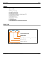
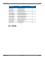
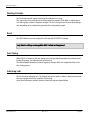
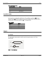
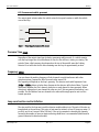
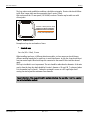
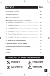
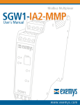
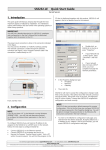
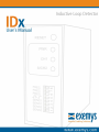
IDx User´s Manual
Exemys
Exemys Products are in constant evolution to satisfy our customer’s needs.
For that reason, the specifications and capabilities are subject to change without prior notice.
Updated information can be found at www.exemys.com
Copyright © Exemys, 2005 All Rights Reserved.
Rev. 4.0.0
www.exemys.com
Rev. 4.0.1
Página 2
IDx User´s Manual
Exemys
Index
FEATURES
5
MODEL CODES
5
WORKING PRINCIPLE
7
RESET
7
AUTO TUNING
7
INDICATING LEDS
7
SENSIBILITY (SENS)
8
OUTPUTS
8
8.1 Pulsed______________________________________________________________ 8
8.2 Permanent while present ________________________________________________ 9
PRESENCE TIME (PRES)
9
FREQUENCY (FREC)
9
LOOP CONSTRUCTION AND INSTALLATION
9
CONNECTION
12
12.1 Connecting each model _______________________________________________ 12
www.exemys.com
TECHNICAL SPECIFICATIONS
13
FACTORY CONFIGURATION
13
GLOSSARY
14
Rev. 4.0.1
Página 3
IDx User´s Manual
Exemys
Figures
Figure 1 – Detail of the Codification of the models _________________________________________________5
Figure 2 – Available Models __________________________________________________________________6
Figure 3 – Pulsed output signal________________________________________________________________8
Figure 4 - Output signal permanent while present _________________________________________________9
Figure 5 – Loop construction ________________________________________________________________10
Figure 6 - Proper installation of the loop ________________________________________________________11
Figure 7 – Connection _____________________________________________________________________12
Figure 8 – Optoisolated outputs, Transistor, Relay and TTL. _________________________________________12
Figure 9 – Factory Configuration______________________________________________________________13
Tables
Table 1 – Indicating LED’s state _______________________________________________________________8
Table 2 - Sensibility ________________________________________________________________________8
Table 3 - Connection ______________________________________________________________________12
www.exemys.com
Rev. 4.0.1
Página 4
IDx User´s Manual
Exemys
Features
Microcontroller.
1 or 2 channels.
Switching power supply.
4 settable sensibility levels.
4 settable frequency levels.
Optoisolated, relay, transistor or digital outputs (TTL).
Safe output in case of failure.
Channel multiplexing.
Advanced failure analysis.
Auto-tuning.
Output while present
Drift compensation due to environmental fluctuations
Model Codes
IDX-XX-0-XX-P
Activated while present
Normal Output
Output Type (Optoailated Relay, Transistor or TTL)
Channels (1 or 2)
Inductive Detector
Figure 1 – Detail of the Codification of the models
www.exemys.com
Rev. 4.0.1
Página 5
IDx User´s Manual
Exemys
PART NUMBER
OUTPUTS
CHANNELS
ID1-RL-0-NA-P
Normally Open Relay
1
ID2-RL-0-NA-P
Normally Open Relay
2
ID1-RL-0-NC-P
Normally Closed Relay
1
ID2-RL-0-NC-P
Normally Closed Relay
2
ID1-OP-0-NOFF-P
Optoisolated Normally OFF
1
ID2-OP-0-NOFF-P
Optoisolated Normally OFF
2
ID1-OP-0-NON-P
Optoisolated Normally ON
1
ID2-OP-0-NON-P
Optoisolated Normally ON
2
ID1-TR-0-NOFF-P
Transistor Normally OFF
1
ID2-TR-0-NOFF-P
Transistor Normally OFF
2
ID1-TT-0-N0-P
ID2-TT-0-N0-P
TTL Normally OFF
1
TTL Normally OFF
2
Figure 2 – Available Models
www.exemys.com
Rev. 4.0.1
Página 6
IDx User´s Manual
Exemys
Working Principle
The IDx detects metallic masses measuring the inductance of a loop.
This loop is part of an oscillating circuit that generates a magnetic field. When a vehicle passes
over the loop the oscillator’s frequency changes. The IDx’s microprocessor detects these changes
and, depending on its configuration, generates the corresponding output.
Reset
The RESET button is used to configure the IDx with the DIP SWITCH’s settings.
Every time the settings are changed the RESET button must be pressed.
Auto Tuning
When the IDx is turned on, the auto tuning process begins which determines the reference level.
During this process, the indicating leds are turned on.
The environmental fluctuations produce frequency changes which are compensated due to the
auto tuning process.
Indicating Leds
The IDx has three indicating leds. The channel leds turn on when a vehicle is detected and remain
this way until the vehicle has completely left the loop.
Apart from indicating a vehicle’s presence, these leds indicate channel failure.
www.exemys.com
Rev. 4.0.1
Página 7
IDx User´s Manual
Exemys
Table 1 – Indicating LED’s state
Led CH1 and CH2
STATE
1 Flash
Short-circuit in loop
2 Flashes
Disconnected loop or frequency too low.
3 Flashes
Frequency too high
Led on
Vehicle detection
Sensibility (SENS)
Each channel has 4 configurable sensibility levels. This sensibility is specified as δL/L [%]: the
minimum change (δL), the loop’s inductance must suffer, divided the loop’s inductance (with no
vehicle present). A cars typical sensibility is δL/L=3% approximately.
Table 2 - Sensibility
δL/L %
0.50
0.10
0.05
0.02
SENSIBILITY
Low
Medium
High
Very High
Outputs
8.1 Pulsed
The output signal activates when the vehicle enters the loop and remains on for 120 ms
approximately.
LED
Vehicle over the loop
OUTPUT
120 ms
Figure 3 – Pulsed output signal
www.exemys.com
Rev. 4.0.1
Página 8
IDx User´s Manual
Exemys
8.2 Permanent while present
The output signal activates when the vehicle enters the loop and remains on while the vehicle
crosses the loop.
LED
Vehicle over the loop
OUTPUT
Figure 4 - Output signal permanent while present
Presence Time (PRES)
Regardless of the output signal type (pulsed or permanent while present), if a vehicle remains
over the loop longer than a certain amount of time, the IDx will reset, causing a re-tuning. This
period of time, called presence time, depends on the size of the metallic mass that’s being
detected. A car will reset the IDx after remaining over the loop for approximately an hour.
Frequency (FREC)
You can choose the working frequency of both channels to avoid interference with other
detection systems. Frequencies differ from each other around 5%.
The frequency will depend on the loop’s geometry. The detector works with frequencies from
25Khz to 120KHz. Above or below those frequencies the detector will indicate failure. To avoid
interference between the IDx’s channels, detection on each channel is done separately. When
detection is taking place in one channel the other one is off, this way mutual interference is not
possible. The IDx switches from one channel to the other with enough speed as not to affect
normal operation.
Loop construction and installation
The wire used for the loop must reach the detector module without cuts. The ends of the wire are
brought back to the enclosure. This sector of wire must be twisted, at least 25 turns per meter ( 8
per feet), and it can’t exceed 100m (330 feet). If the cut in pavement is shared by the channels,
increasing the number of turns per meter and using shield wires is recommended (shield must be
ground connected in detection module).
www.exemys.com
Rev. 4.0.1
Página 9
IDx User´s Manual
Exemys
The loop, unless under prohibitive conditions, should be rectangular. Shorter sides should follow
traffic flow. Longer sides must be separated at least 1 meter (3 feet).
Wire section must be 1.5 mm square (14/16 AWG) or above. The wire may be multi core with
silicon jacket.
25 turns / meter (8 turns / feet)
100 m (330 feet) Maximum
Figure 5 – Loop construction
Examples on loop size and number of turns:
Standard Loop
2m x 1m (6.5 x 3 feet), 3 turns
When installing two loops, of different detection modules, at close ranges you should choose
different working frequencies for each loop, to avoid interference. In any case, loops should be at
least two meters apart. When both loops are connected to the same IDx this restriction doesn’t
apply.
The loop is installed in a cut in pavement. The cuts should be wider than the diameter of the wire
used to form the loop; the depth should be N x wire’s diameter + 20 mm (1/8 “) or deeper (where
N is the number loop’s of turns). Cutting the rectangle’s corners at a 45º angle helps avoid
curving the wire beyond the maximum curve-diameter.
Proper installation of the loop will result in optimal detection. If a loop fails, it can’t be repaired
due to the installation method.
www.exemys.com
Rev. 4.0.1
Página 10
IDx User´s Manual
Exemys
Sealer
Pavement Cuts
Traffic Flow
PAVEMENT
LOOP
Figure 6 - Proper installation of the loop
Fill the pavement’s cuts with epoxy resin, avoiding moisture or other materials since this could
affect the measurements.
When placing a new loop, remove the old one. If this is not possible separate and isolate the wire
ends.
www.exemys.com
Rev. 4.0.1
Página 11
IDx User´s Manual
Exemys
Connection
OUTPUT 2
2
6
5
7
4
8
3
9
2
LOOPS
-
1 11
+
10
CHASIS GROUND
OUTPUT 1
10-30 VDC
Figure 7 – Connection
12.1 Connecting each model
7 y 10
8 y 11
OPTOISOLATED (OP)
7 y 10
8 y 11
TRANSISTOR (TR)
7 y 10
8 y 11
8 y 11
7 y 10
RELAY (RL)
TTL (TT)
Figure 8 – Optoisolated outputs, Transistor, Relay and TTL.
Table 3 - Connection
www.exemys.com
Pin
Description
1
+ Vdc (10-30V)
2
GND
3
Loop Channel 1
4
Loop Channel 1
5
Loop Channel 2
6
Loop Channel 2
7
Relay output 2 (NA-NC) / Opto + / TR+ / GND
8
Relay output 2 (Common) / Opto - / GND / TTL
9
Chassis ground
10
Relay output 1 (NA-NC) / Opto + / TR+ / GND
11
Relay output 1 (Common) / Opto - / GND / TTL
Rev. 4.0.1
Página 12
IDx User´s Manual
Exemys
Technical Specifications
Power Supply
10-30 Vdc, internal switching power source.
Operating current
100mA max.
Relay
0.5ª 120Vca, 1ª 24Vdc, 0.3ª 60Vdc.
Optoisolators
Optoisolated output, 30V max, 10mA max.
Transistor
Transistor output, 30V max, 100mA max.
TTL
Digital output TTL (0-5V)
Protections
Varistors in power supply and relay outputs. Lightning protection and ground
terminators. Loop input isolation with transformer.
Inductance range
20uHy a 2000uHy. Factor Q>5
Frequency range
25Khz a 120Khz
Presence time
1hour for δL/L = 3%
Sensibility
δL/L = 0.02%, 0.05%, 0.1%, 0.5%
Mux time
10mS
Enclosure
Polycarbonate (top) y Noril (base), UL94-V0, Grey RAL 7035.
Factory Configuration
ON
ON
VERY HIGH
HIGH
8
7
6
5
4
MEDIUM
LOW
2
1
FRECUENCY
PRESENCE
SENS. CH 1
SENS. CH 2
Figure 9 – Factory Configuration
www.exemys.com
Rev. 4.0.1
Página 13
IDx User´s Manual
Exemys
Glossary
Drift: Frequency change due to environmental fluctuations.
Delta L/L (δL/L): change in the loop’s inductance caused by an object over it, divided the loop’s
inductance without objects over it.
Loop: wire wound in a given shape, placed in the detection zone.
Startup: process that takes place when the detector is turned on, or when RESET is pressed, in
which the settings of the DIP SWITCH are read and the reference level is determined.
Led: Light emitting diode
Sensibility: signal level that produces a detection output. Usually expressed in δL/L.
Presence time: Maximum activation time of a loop before the detector resets.
www.exemys.com
Rev. 4.0.1
Página 14