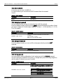
1
RME1-AI User Manual - Analog Variables Acquisition Module
Exemys
Exemys Products are in constant evolution to meet our customers´ needs. For that reason,
specifications and capabilities are subject to change without previous notice.
Updated information can be found at www.exemys.com
Copyright © Exemys, 2006. All rights reserved
Rev. 3.0
www.exemys.com
Rev. 3
Page 2
RME1-AI User Manual - Analog Variables Acquisition Module
Exemys
Index
INTRODUCTION
6
1.1 About this manual _______________________________________________________ 6
1.1.1
1.1.2
Purpose of this manual
Conventions, terms and acronyms
6
6
1.2 Product General Description ________________________________________________ 7
1.3 RME1-AI models codification _______________________________________________ 8
INSTALLATION
9
2.1 Connectors general diagram________________________________________________ 9
2.2 Power connection ______________________________________________________ 10
2.3 RS-232 serial port connection (only for configuration) ____________________________ 11
2.4 Ethernet connection _____________________________________________________ 12
2.4.1 Hub or Switch connection _______________________________________________ 12
2.5 Analog Inputs Description ________________________________________________ 13
2.6 Analog inputs connection _________________________________________________ 14
2.6.1
2.6.2
Voltage output sensor connection
Current loop output sensor connection
14
14
2.7 Indicator Leds code _____________________________________________________ 15
CONFIGURATION
17
3.1 Basic ethernet configuration _______________________________________________ 17
a)
IP address configuration with DHCP
17
3.2 Device parameters configuration____________________________________________ 20
3.2.1
3.2.2
3.2.3
3.2.4
3.2.5
3.2.6
Network configuration
Analog inputs configuration
Scaling
Alarms configuration
Monitor
Advanced configuration
21
22
22
24
25
25
OPERATION
27
Introduction 27
4.1 TCP Modbus operation __________________________________________________ 27
4.2 CVS/XML mode operation_________________________________________________ 28
4.2.1
4.2.2
CSV
XML mode operation
28
29
4.3 SNMP mode operation ___________________________________________________ 31
www.exemys.com
Rev. 3
Page 3
RME1-AI User Manual - Analog Variables Acquisition Module
4.3.1
4.3.2
4.3.3
4.3.4
Exemys
Introduction
MIB
SNMP tree description
SNMP Traps
31
32
32
33
4.4 Web page operation mode (HTTP) __________________________________________ 33
A. THE RME1-AI MOUNTING
A.1.
36
Mounting of the device on DIN rail ______________________________________ 36
B. ORIGINAL MANUFACTURER’S CONFIGURATION
38
C. TECHNICAL SPECIFICATIONS
39
D. CONFIGURATION CONSOLE
41
D.1.
Configuration command console (Serial and TELNET) _________________________ 41
D.2.
Commands ________________________________________________________ 41
D.2.1. Password Command
D.2.2. Host Name Command
D.2.3. NetConfig Command
D.2.4. Factory Reset command
D.2.5. Reset command
D.2.6. Analog Input command
D.2.7. Analog List Command
D.2.8. Scaling command
D.2.9. Aalarm command
D.2.10. Aname Command
D.2.11. Aselect command
D.2.12. SNMPEnable command
D.2.13. SNMPTrapsEnable command
D.2.14. SNMPManager1 command
D.2.15. SNMPManager2 command
D.2.16. SNMPReadCN command
D.2.17. SNMPWriteCN command
D.2.18. SNMPTrapCN command
D.2.19. More Configuration commands
41
42
42
42
43
43
43
43
44
44
44
44
44
45
45
45
45
45
46
E. ARP METHOD TO CONFIGURE IP ADDRESS
48
Figures
Figure 1 - Usage general diagram
Figure 2 - Models Codification Details
Figure 3 - Connectors general diagram
Figure 4 - Power connection diagram
Figure 5 - Serial and Ethernet connectors position.
Figure 6 - Serial RS-232 terminal detail.
Figure 7 - Serial connection cable to communicate with a PC
Figure 8 - Straight-through cable scheme
Figure 9 - RJ45 connector
www.exemys.com
Rev. 3
7
8
9
10
11
11
12
12
12
Page 4
RME1-AI User Manual - Analog Variables Acquisition Module
Exemys
Figure 10 - RME1-AI analog inputs in each channel arrangement
Figure 11 - 0-10Vdc output transducers / sensors connection
Figure 12 - Transducers / sensors with 4-20mA current loop output connection
Figure 13 - Leds indicators
Figure 14 - Exemys device locator
Figure 1 - Device Locator, Properties
Figure 16 - Enter the IP address in the Web browser.
Figure 17 - Enter the host in the Web browser
Figure 18 - Net configuration
Figure 19 - Inputs configurations
Figure 20 - Scaled value without decimal
Figure 21 - Scaled value with decimal
Figure 22 - Scaling configuration
Figure 23 - Alarms configuration
Figure 24 - User’s monitor configuration
Figure 25 - Advanced options
Figure 26 - CSV analog example
Figure 27 - SNMP configuration
Figure 28 - Administrator Monitor
Figure 29 - User’s monitor
Figure 30 - Network Configuration.
Figure 31-Device assembly
Figure 32 - Device disassembly
13
14
14
15
18
19
20
21
21
22
23
23
24
24
25
26
29
32
34
34
35
36
37
Tables
Table 1 - Acronyms_________________________________________________________________________6
Table 2- Terms ____________________________________________________________________________7
Table 3 - Conventions_______________________________________________________________________7
Table 4 - Indicator Leds ____________________________________________________________________15
Table 5 - SNMP tree description ______________________________________________________________32
Table 6 - SNMP Traps ______________________________________________________________________33
Table 7 - Original manufacturer’s configuration ___________________________________________________38
Table 8 - PASSWORD Command ______________________________________________________________42
Table 9 - HOSTNAME Command ______________________________________________________________42
Table 10 - NETCONFIG Command _____________________________________________________________42
Table 11 - FACTRESET Command _____________________________________________________________42
Table 12 - RESET Command _________________________________________________________________43
Table 13 - AINPUT Command ________________________________________________________________43
Table 14 - ALIST Command__________________________________________________________________43
Table 15 - SCALING Command _______________________________________________________________43
Table 16 - AALARM Command _______________________________________________________________44
Table 17 - ANAME command ________________________________________________________________44
Table 18 - ASELECT command________________________________________________________________44
Table 19 - SNMPENABLE command ___________________________________________________________44
Table 20 - SNMPTRAPSENABLE command_______________________________________________________44
Table 21 - SNMPMANAGER1 command ________________________________________________________45
Table 22 - SNMPMANAGER2 command ________________________________________________________45
Table 23 - SNMPREADCN command ___________________________________________________________45
Table 24 - SNMPWRITECN command __________________________________________________________45
Table 25 - SNMPTRAPCN command ___________________________________________________________45
Table 26 - More Commands _________________________________________________________________46
Table 27 - Telnet commands _________________________________________________________________46
www.exemys.com
Rev. 3
Page 5
RME1-AI User Manual - Analog Variables Acquisition Module
Exemys
Chapter 1
Chapter
Introduction
1.1 About this manual
1.1.1 Purpose of this manual
The purpose of this manual is to provide instructions to install and operate the RME1-AI in a quick
and easy way.
The manual starts with a general description of the product followed by instructions to install its
hardware correctly. Further on the RME1-AI configuration and operation are provided in detail.
This manual can be used for the v2.0.0 or higher firmware version. For previous versions, consult
[email protected].
1.1.2
Conventions, terms and acronyms
The acronyms used in this manual are listed below.
Table 1 - Acronyms
www.exemys.com
Acronym
Description
ARP
Bps
HTTP
IP
LAN
NBNS
PC
UDP
TCP
DHCP
GND
CSV
XML
SNMP
Address Resolution Protocol
Bits per second
HyperText transfer Protocol
Internet Protocol
Local Area Network
NetBios Name Server
Personal Computer
User Datagram Protocol
Transmission Control Protocol
Dynamic Host Configuration Protocol
Ground (Reference)
Comma Separated Value
Extensible Markup Language
Simple Network Management Protocol
Rev. 3
Page 6
RME1-AI User Manual - Analog Variables Acquisition Module
Exemys
Table 2- Terms
Terms
Description
IP Address
A device’s logical address within a network.
NetMask
Defines which part of the IP Address belongs to the
subnet.
Gateway
Output for other networks.
The conventions listed below are used in this manual.
Table 3 - Conventions
Conventions
Description
A|B|C
A set of possible values for command parameters. You can type
A, B or C.
n..m
A range of possible values. You can type any value in the range
including n and m.
aaa.bbb.ccc.ddd
An IP address.
1.2 Product General Description
The RME1-AI is a complete interface for your analog sensors. It allows monitoring and
supervising, from any PC connected to the same network, analog devices with either current loop
or voltage range output.
The RME1-AI works in differential mode, it means it can measure the difference between the
absolute values of two signals.
The information can be read by any of the four RME1-AI work modes.
4 Work Modes
TCP Modbus
Web Page
4-20 mA
0-10 Vdc
0-100 Vdc
Ethernet
CSV / XML
SNMP
RME1-AI
…
Analog
Transducer #0
Analog
Transducer #7
Figure 2 - Usage general diagram
www.exemys.com
Rev. 3
Page 7
RME1-AI User Manual - Analog Variables Acquisition Module
Exemys
1.3 RME1-AI models codification
RME1-AI-100-00-80-IA3
RS232 Serial Ports
RS485 Serial Ports
RS422 Serial Ports
Case
Digital Inputs
Digital Outputs
Analog Outputs
Analog Inputs
Figure 3 - Models Codification Details
www.exemys.com
Rev. 3
Page 8
RME1-AI User Manual - Analog Variables Acquisition Module
Exemys
Chapter 2
Chapter
Installation
2.1 Connectors general diagram
On the device frontal connector there can be found the power input terminals as well as the
terminals of the different communication ports.
+
1
Vin
+
2
GND
3
NC
NC = No Connection
4
NC
NC = No Connection
5
NC
NC = No Connection
6
TX
TX = Transmits Data
7
RX
RX = Receives Data
8
GND
-
Power Supply
10-30 Vdc
1
2
3
4
5
6
7
8
RS232
DTE
GND = Signal Ground
Figure 4 - Connectors general diagram
www.exemys.com
Rev. 3
Page 9
RME1-AI User Manual - Analog Variables Acquisition Module
Exemys
2.2 Power connection
The picture belows shows the power input connection. It is found in the first two terminals called
Vin (+) and GND (-).The RME1-AI power connection has polarity and it accepts the range of 10 to
30 Vdc.
Power Supply
10-30 VDC
Vin
+
1
GND
2
-
3
1
2
3
4
4
5
6
5
7
8
6
7
8
Figure 5 - Power connection diagram
www.exemys.com
Rev. 3
Page 10
RME1-AI User Manual - Analog Variables Acquisition Module
Exemys
2.3 RS-232 serial port connection (only for configuration)
The RME1-AI has one configuration serial port whose connection terminals are shown in the
picture below. The configuration serial port is available for all the RME1-AI models. The same
picture also shows where the Ethernet connector is placed.
Note: The configuration method through serial port is an alternative. The suggested method is
through the configuration WEB page.
Power Supply
1
2
3
4
5
RS232 Serial Ports
Terminal Blocks
6
7
8
RJ45 Connector
Ethernet Connector
Figure 6 - Serial and Ethernet connectors position.
1
2
3
1
2
4
3
4
5
5
6
7
8
RS232
Tx
6
Rx
7
GND
8
Figure 7 - Serial RS-232 terminal detail.
www.exemys.com
Rev. 3
Page 11
RME1-AI User Manual - Analog Variables Acquisition Module
Exemys
For configuration, a connection cable can be used as it is shown in picture 7.
PC
RME1-AI
DB9 Female
RxD 2
Tx
6
TxD 3
Rx
7
GND 5
GND 8
Figure 8 - Serial connection cable to communicate with a PC
2.4 Ethernet connection
The RJ45 connector is for Ethernet connection. This connection is essential for the RME1-AI to
work.
2.4.1 Hub or Switch connection
To connect the RME1-AI to Ethernet through a Hub or Switch, it is necessary to use a straightthrough UTP network cable.
Rx + (1)
Rx - (2)
Tx + (3)
Tx - (6)
Rx + (1)
Rx - (2)
Tx + (3)
Tx - (6)
Figure 9 - Straight-through cable scheme
Rx + (1)
1
8
Rx - (2)
Tx + (3)
Tx - (6)
Figure 10 - RJ45 connector
www.exemys.com
Rev. 3
Page 12
RME1-AI User Manual - Analog Variables Acquisition Module
Exemys
2.5 Analog Inputs Description
In Figure 10 it can be seen where the RME1-AI analog terminals are placed. The
inputs are in columns on both sides of the equipment.
The inputs start numbering from 0. So that the first channel is CH0.
The same way, each terminal is numbered for its function and the channel it belongs to. So, the
RME1-AI first terminal in channel 0 is called CH0 COM.
Channel detail
CH0 CH1 CH2 CH3
COM
COMMON (inputs)
V +
V+ (Voltage inputs)
I +
I+ (Current inputs)
FRONTAL
VIEW
I+ (Current inputs)
V+ (Voltage inputs)
COMMON (inputs)
CH4 CH5 CH6 CH7
Figure 11 - RME1-AI analog inputs in each channel arrangement
www.exemys.com
Rev. 3
Page 13
RME1-AI User Manual - Analog Variables Acquisition Module
Exemys
2.6 Analog inputs connection
2.6.1 Voltage output sensor connection
Sensors with voltage outputs (from 0 up to 10 Vdc) must be connected to the
RME1-AI as it is shown in the following figure.
All the RME1-AI channels are fit for this kind of sensors.
0-10Vdc
RME1
CH0 CH1 CH2 CH3
Humidity
Temperature
Level
Pressure
Signal Common
COMMON (inputs)
Voltage Output
0-10Vdc
+
V+ (Voltage input)
I+ (Current input)
Flow
TRANSDU CER / SENSOR
FRONTAL VIEW
( w ith v olt age ou tput 0 -1 0Vdc )
Figure 12 - 0-10Vdc output transducers / sensors connection
2.6.2 Current loop output sensor connection
In this case, the figure shows the way sensors with current loop outputs (4 –20mA) can be
connected. All the RME1-AI channels are fit for this kind of usage.
The value of the input impedance for each way is Zi=150 Ω
4-20mA
RME1
CH0 CH1 CH2 CH3
Humidity
Temperature
Level
Pressure
Signal Common
Output Current
4-20mA
COMMON (inputs)
*
Flow
TRANSDU CERS / SENSOR S
(w ith v olt age output 4-20mA )
FRONTAL VIEW
V+ (Voltage input)
I+ (Current input)
Important Note:
* A external bridge
must be made
between I+ and V+
of the same channel.
Figure 13 - Transducers / sensors with 4-20mA current loop output connection
www.exemys.com
Rev. 3
Page 14
RME1-AI User Manual - Analog Variables Acquisition Module
Exemys
IMPORTANT
Do not exceed the signal limit for each case (+10 Vdc or 20 mA respectively). Exceeding the
signal level may cause malfunctioning or even permanent damage of the device.
2.7 Indicator Leds code
The RME1-AI has three luminous indicators (LEDs)
-The Power LED indicates that the device is turned on
-The yellow LED shows the Ethernet interface status
-The green LED indicates Modbus TCP status
Power Led
Yellow Led
Green Led
Figure 14 - Leds indicators
Table 4 - Indicator Leds
www.exemys.com
Yellow Led
Green Led
Description
It is steady on
Do not care
RME1-AI is searching for a DHCP server in
the network.
It is ½ second on and ½ second off. Do not care
RME1-AI is starting.
During this period the equipment may be
set in serial configuration mood.
It blinks like a beacon, 90% of a second
off and the remaining 10% on.
Do not care
RME1-AI has an IP address and a carrier
(link) on the connection. This is the normal
operation status.
It is 90% of a second on and the
remaining 10% off.
Do not care
RME1-AI has no IP address and cannot find
a DHCP server. It will search the DHCP
server at 60 seconds interval.
Rev. 3
Page 15
RME1-AI User Manual - Analog Variables Acquisition Module
www.exemys.com
Exemys
It blinks very fast.
Do not care
Absence of Ethernet carrier.
Do not care
It is steady on and it turns off for
short periods of time.
RME1-AI has detected a Modbus TCP
connection.
It flashes alternately with green led
It flashes alternately with yellow
led
Critical failure. (contact technical
support at [email protected])
Rev. 3
Page 16
RME1-AI User Manual - Analog Variables Acquisition Module
Exemys
Chapter 3
Chapter
Configuration
3.1 Basic ethernet configuration
The first step to be taken is the network parameters configuration by any of the following
methods:
a)
b)
c)
d)
DHCP (AUTOMATIC CONFIGURATION)
Exemys Device Locator (Best recommended method)
Serial Port
ARP Method
a) IP address configuration with DHCP
RME1-AI Default configuration is IP 0.0.0.0, so when turned on, it will search a
DHCP server.
RME1-AI tries to negotiate an IP address with the DHCP server for a maximum period of 10
seconds. If the DHCP fails to answer in that period, RME1-AI will show an error code by means of
its indicator LEDs (See Table 4) and will try to establish connection with the DHCP server 60
seconds later. This process will be repeated indefinitely until a DHCP server assigns an IP address
to RME1-AI or until the user assigns a static IP address.
b) IP address configuration with Exemys Device Locator
The Exemys Device Locator Application software is intended to be used for the basic configuration
of any Exemys device over your ethernet network. It allows searching, identifying and configuring
the basic network parameters.
This simple application program is distributed with any Exemys product in the accompanying CD.
You can also download the latest version of this program from the Exemys Web Site
(www.exemys.com).
The Device Locator application must be run from any PC within the network where the Exemys
devices to be configured are installed.
www.exemys.com
Rev. 3
Page 17
RME1-AI User Manual - Analog Variables Acquisition Module
Exemys
Figure 15 - Exemys device locator
When the Device Locator is run for the first time it will search any Exemys device within the
network. If there is an Exemys device in the network it will be shown in Device Locator Grid:
• Device: Name of the device, such as RME-1AI or SSE232-ST
• Mac address: Hardware Ethernet Address of the device.
• Version: Firmware version running in that device.
• Host: Name of the equipment of NBNS identification.
• DHCP: If the Checkbox is activated, the device net parameters will be obtained from a
DHCP server.
• IP: IP address configured in the device.
• Netmask: Subnet mask configured in the device
• Gateway: Output from a net to others.
IMPORTANT
It is not necessary for the device to be properly configured. If the device is correctly connected
and working, it will be found by the Device Locator Application Program.
To refresh the grid, click on the “Query Network” button. This action will make the Device
Locator search any Exemys device in the network again.
You can change any of these basic network parameters within the Device Locator software.
•
www.exemys.com
Select the device in the grid and click on the “Properties” button, or open the “Actions”
menu and select the “Properties” command. You will see the Properties dialog box.
Rev. 3
Page 18
RME1-AI User Manual - Analog Variables Acquisition Module
Exemys
•
All Exemys devices provide a Remote Configuration Password. This password is used by
the Web configuration page and remote command Console in the device.
•
If the device has a configured password, enter the password in the Device Password box.
The default value is blank.
•
You can type an IP address, Netmask and
Gateway IP Address or you can click on
the “Use DHCP” check box to make the
device search a DHCP Server. The RME1AI has been manufactured with the DHCP
feature activated.
•
You can give the device a personal name
within the field “Host Name”.
•
Click on the OK button for the Device
Locator send this information to the
device.
•
If the password is not correct, you will
see the message “Error when changing
the configuration”. Check the equipment
to be configured password. The device
will not answer any message sent by the
Device Locator during the first five
seconds after an incorrect password. This
is to avoid any brute force method to change the network parameters of the device.
If the device does not respond, the Device Locator will show a “No Response from
Device” message. Make sure the device is turned on and connected to the ethernet
network.
The Exemys device will reset so the changes in the configuration take effect.
If no change is necessary, click on the “Close” button to close the Properties dialog box.
After a few seconds the device being reset will answer again to the requests of the Device
Locator software. Click on the “Query network” button to refresh the grid and make sure
the parameters were changed.
Figure 16 - Device Locator, Properties
•
•
•
•
c) IP address configuration with serial port
Connecting the serial port of the PC to the serial port of the equipment (See Chapter II), you can
use a software such as the Hyperterminal (Windows) to be connected with the equipment and
modify all its parameters . Once the port is opened with the serial parameters configuration at
9600,8,N,1, the RME1-AI must turn on and type ”cfg” followed by ENTER with the Hyperterminal
before 7 seconds have elapsed from the moment it is turned on. You will get access of the
configuration through serial port and will see :
www.exemys.com
Rev. 3
Page 19
RME1-AI User Manual - Analog Variables Acquisition Module
Exemys
RME1-AI – Exemys : (or similar) on the screen
--------------->_
It is important to mention that this way not only the network parameters can be modified but also
all the equipment parameters can be reached. For further information consult Appendix D.
d) IP address configuration with ARP method
If RME1-AI receives PING packets after being turned on, it will take the destination IP of these
packets and this will start being the device IP address. For further information see appendix E.
3.2 Device parameters configuration
Configuration parameters can be modified by three different ways:
- Web page configuration
- Telnet console configuration (See appendix D)
- Serial console configuration (See appendix D)
Once the RME1-AI has a valid IP address you may access the web page to configure the rest of
the parameters.
1. If your web navigator is configured to search for a Proxy server, disable that option.
2. If you have the Exemys Device Locator software, select the device and press the button
“Configure”.
3. Type the RME1-AI IP address field of your navigator.
Figure 17 - Enter the IP address in the Web browser.
4. In your web browser you will see the inputs value and a link to configure the device.
If you click on the link the RME1-AI will ask for the password to enter the page. Type “admin” as
user name and then the password to enter.
The RME1-AI defaults have no password, so that the device will not ask for it unless the user
enables it.
www.exemys.com
Rev. 3
Page 20
RME1-AI User Manual - Analog Variables Acquisition Module
Exemys
Figure 18 - Enter the host in the Web browser
As it is shown in the above figure, the name of the analog module in the manufacturer’s
configuration is: RME1-AI (last digits from Mac address) , and this name can be changed using
the Exemys Device Locator by means of the Host name parameter, in properties.
For example, if the Mac address of the device is 00:0B:FA:30:10:4b, The name in the
manufacturer’s configuration will be RME1-AI- 30104B.
In several sections of the web interface, the RME1-AI has a help symbol “? ”. If you click on it,
you will get a help window for the configuration section you are.
3.2.1 Network configuration
Network parameters can be configured by all the methods already mentioned but it can be done
though the WEB interface too.
It is important to make it clear that the name of the device is useful for two tasks. One of them is
to identify each device in the Exemys Device Locator, when a searching is in progress. The other
is to use the name of the device instead of its IP address (NBNS protocol)
The NBNS ( NetBios Name Server) allows the user, in case of ignoring or simply not remembering
the module IP address, search it literally through the name in the LAN net from a web browser.
Figure 19 - Net configuration
www.exemys.com
Rev. 3
Page 21
RME1-AI User Manual - Analog Variables Acquisition Module
Exemys
3.2.2 Analog inputs configuration
Analog inputs have two configuration fields:
Input type: It allows to choosing between voltage input (0-10V) or current loop input (420mA).
Filter: It allows selecting the amount of samples to take before determining a readings
average for the corresponding input. This average is the value shown by the input when it
is consulted. The possible values are: 1, 5, 10, 20, 50 or 100 samples.
Figure 20 - Inputs configurations
3.2.3 Scaling
The RME1-AI can acquire a value and make a simple calculation before assigning it to the final
value. It supports the Linear (Y=Ax+B) functions where X is the acquired value and Y will be the
value observed in the field “Scaled Value”
To determine the scaling of an analog input it is necessary to configure 2 coordinates of the plane
XY, through which the scaling straight line passes.
The limits for these configuration values are the following:
X values between 0 and 4000 ( 0 and 10 Vdc and 20 mA respectively)
Y values between –32.767 and 32.767
Decimals: Values between 0 and 4 (only for “Scaled value “ on the WEB)
The factory default is a straight line with slope 1 and which passes through the origin (X0=0
YO=0 X1=1 Y1=1), and the amount of decimals is zero (0).
To make it clear how to use these parameters, you have this example:
Suppose that you have a sensor that will output 0V for 10ºC and 10V for 100ºC. If you want
to see the temperature value in the RME1-AI, the scaling will be:
X0= 0 Y0=10 X1=4000 Y1=100 Decimals=0
www.exemys.com
Rev. 3
Page 22
RME1-AI User Manual - Analog Variables Acquisition Module
Exemys
As you can see in the following figure, when the RME1-AI gets in the ·Converter Value” 4000,
you will see 100 in “Scaled Value”.
Y [ºC]
100 ºC
(X1,Y1)
10 ºC
(X0,Y0)
0
4000
X [Converter Value]
Figure 21 - Scaled value without decimal
If you want to increase the accuracy in the measurement, you can configure the scaling as
follows: X=0 Y0=100 X1=4000 Y1=1000 Decimals=1
Y [ºC]
100,0 ºC
(X1,Y1)
10,0 ºC
(X0,Y0)
0
4000
X [Converter Value]
Figure 22 - Scaled value with decimal
www.exemys.com
Rev. 3
Page 23
RME1-AI User Manual - Analog Variables Acquisition Module
Exemys
Figure 23 - Scaling configuration
3.2.4 Alarms configuration
The RME1-AI has two alarms for each analog input. You will be able to enable, disable and
modify the set point for each one.
IMPORTANT: Alarms are compared with the scaled value without decimals.
Figure 24 - Alarms configuration
www.exemys.com
Rev. 3
Page 24
RME1-AI User Manual - Analog Variables Acquisition Module
Exemys
Returning with the example of temperature measurement, if you need the alarm to be activated
when the temperature is out of the range 20º C and 85º C (decimals=0), you need to configure
the parameters “Low Value” in 20 and “High value” 85. If the range is 20,0º C and 85,0º C
(decimals=1), the parameters “Low value” and “High value” have to be configured in 200 and
850 respectively.
3.2.5 Monitor
In the monitor web page you can configure the user’s monitor page.
This configuration consists in selecting the inputs you want to visualize, the name you assign to
each input, and the data column you want to visualize in this monitor code. (Analog value, Scaled
value or Converter value).
The scaled value will show as many decimals such as it has been configured on the scaling screen.
The Converter goes from 0 up to 4000 (4000 = 10V or 20mA respectively).
Figure 25 - User’s monitor configuration
IMPORTANT
Each name can be formed for up to 16 characters.
3.2.6 Advanced configuration
Among the possible advanced configurations you can find:
Change password: It allows changing manufacturer’s default password for another one.
Note: The user name must be “admin”
www.exemys.com
Rev. 3
Page 25
RME1-AI User Manual - Analog Variables Acquisition Module
Exemys
Reset the device: It can be used to reset the device in the same way it can be done by
cutting the power.
Set device to factory default: It allows to change all configuration parameters to
manufacturer’s default. Be careful. See values in Appendix B.
Modbus exceptions: Enable or disable Modbus exceptions.
Figure 26 - Advanced options
www.exemys.com
Rev. 3
Page 26
RME1-AI User Manual - Analog Variables Acquisition Module
Exemys
Chapter 4
Chapter
Operation
Introduction
The RME1-AI has four different work modes. These are:
Modbus TCP
CSV / XML
SNMP
Web page (HTTP)
4.1 TCP Modbus operation
In the RME1-AI each analog input, matches with one Modbus TCP Holding Register. This way ,
once the communication has been established, data is moved in a transparent way from the
analog channels to the corresponding Modbus TCP address.
MODBUS TCP Register
Description
40.001 up to 40.008
Analog value (Input value in voltage or current multiplied by 100).
40.009 up to 40.016
www.exemys.com
Status (Shows the status of each analog input, for current inputs).
0: Normal.
1: Low alarm.
2: High alarm.
40.017 up to 40.024
Scaled value.
40.025 up to 40.032
Value (Analog to Digital converter value, 0 if analog input values is 0V or 0mA, 4000 if
analog input values is 10V or 20mA)
40.101
40.102
40.103 up to 40.105
Firmware Version
Hardware Version
Serial Number
40.201 up to 40.208
Input type
0= Current
1= Voltage
Rev. 3
Page 27
RME1-AI User Manual - Analog Variables Acquisition Module
40.209 up to 40.216
40.217 up to 40.224
40.225 up to 40.232
40.233 up to 40.240
40.241 up to 40.248
40.249 a 40.256
Exemys
Filter (Samples)
1, 5, 10, 20, 50, 100
Abscissa zero (X0) (between 0 and 4.095)
Ordinate zero (Y0) (between -32.767 and 32.767)
Abscissa one (X1) (between 0 and 4.095)
Ordinate one (Y1) (between -3.2767 and 32.767)
40.257 a 40.264
Alarms enable
0: Both alarms disabled
1: Low alarm enabled
2: High alarm enabled
3: Both alarms enabled
Low set point (between - 32.767 and 32.767)
40.265 a 40.272
High set point (between - 32.767 and 32.767)
The registers with gray background can be modified with Modbus TCP. All the others are read only registers.
Registers from 40.033 up to 40.100 and from 40.106 up to 40.200 are reserved bank of memory.
Registers from 40.001 up to 40.032 are read only and show information about each analog input
status.
Registers from 40.101 up to 40.105 show information about the device (read only).
Registers from 40.201 up to 40.272 are read/write registers and store the following information
about the analog inputs configuration:
Input type: Voltage or current loop.
Filter: Samples to take before determining the value.
Scaling: RME1 supports, pointing out two coordinates of a straight line (x0, y0; x1, y1), to
make a linear scaling of each one analog input.
Alarms enable: RME1-AI has two alarms for each analog input, and each one can be
enabled or disabled.
Low alarm: Low alarm set point.
High alarm: High alarm set point.
4.2 CVS/XML mode operation
4.2.1 CSV
If you want to make an automatic data acquisition through other query method under HTTP, the
RME1-AI has 3 web pages where you can get, in plain text format delimited by commas, its
analog inputs status
The available information in these pages is as follows:
ad. CSV: Analog to digital converter value for each one of the eight inputs (0 a 4000 for 0V to
10V or 0mA to 20A).
www.exemys.com
Rev. 3
Page 28
RME1-AI User Manual - Analog Variables Acquisition Module
Exemys
analog. CSV: Analog value multiplied by 100 in mA or in volts depending on the input type
configuration.
scaled. CSV: Engineering units value for each analog input.
Any time you access to any of these 3 pages, you can get updated information from the analog
module.
Figure 27 - CSV analog example
For this example if the inputs are configured in voltage type, analog values are:
Input 0: 0.42V
Input 1: 0.96V
Input 2: 0V
Input 3: 0.24V
Input 4: 0.49V
Input 5: 0.70V
Input 6: 0.39V
Input 7: 1.60V
Example:
If you want to visualize the scaled value, from a work sheet (Microsoft Excel®), execute the
command “Open File” and in its name write:
http://192.168.0.240/scaled.csv (192.168.0.240 is RME1-AI ip address).
Bear in mind that the information belongs to the inputs value at the moment you opened the file.
4.2.2 XML mode operation
To make an automatic information acquisition, the RME1-AI has a web page in which all
configuration and status information is available in XML format.
The name of this page is rme1-ai.xml (this page is within RME1-AI). Any time you access to this
page you can get the following updated information from the analog module:
www.exemys.com
Rev. 3
Page 29
RME1-AI User Manual - Analog Variables Acquisition Module
Exemys
- <RME1-AI>
- <INFO>
<FIRMWARE>V2.0.0</FIRMWARE>
<MACADDRESS>000BFA30104B</MACADDRESS>
</INFO>
- <NETWORK>
<IPADDRESS>192.168.0.223</IPADDRESS>
<NETMASK>255.255.255.0</NETMASK>
<GATEWAY>192.168.0.200</GATEWAY>
<HOSTNAME>RME1-AI-30104B</HOSTNAME>
</NETWORK>
- <AINPUTS>
- <AINPUTSTABLE>
- <ENTRY-0>
<NUMBER>0</NUMBER>
<NAME>Input 0</NAME>
<AVALUE>00.00</AVALUE>
<AUNIT>mA</AUNIT>
<SVALUE>0000</SVALUE>
<CVALUE>0000</CVALUE>
<ALARM>LOW</ALARM>
</ENTRY-0>
- <ENTRY-1>
<NUMBER>1</NUMBER>
<NAME>Input 1</NAME>
<AVALUE>00.00</AVALUE>
<AUNIT>mA</AUNIT>
<SVALUE>0000</SVALUE>
<CVALUE>0000</CVALUE>
<ALARM>LOW</ALARM>
</ENTRY-1>
- <ENTRY-2>
<NUMBER>2</NUMBER>
<NAME>Input 2</NAME>
<AVALUE>00.00</AVALUE>
<AUNIT>mA</AUNIT>
<SVALUE>0000</SVALUE>
<CVALUE>0000</CVALUE>
<ALARM>LOW</ALARM>
</ENTRY-2>
- <ENTRY-3>
<NUMBER>3</NUMBER>
<NAME>Input 3</NAME>
<AVALUE>00.00</AVALUE>
<AUNIT>mA</AUNIT>
<SVALUE>0000</SVALUE>
<CVALUE>0000</CVALUE>
<ALARM>LOW</ALARM>
</ENTRY-3>
- <ENTRY-4>
<NUMBER>4</NUMBER>
<NAME>Input 4</NAME>
<AVALUE>00.00</AVALUE>
<AUNIT>mA</AUNIT>
<SVALUE>0000</SVALUE>
<CVALUE>0000</CVALUE>
<ALARM>LOW</ALARM>
</ENTRY-4>
- <ENTRY-5>
<NUMBER>5</NUMBER>
<NAME>Input 5</NAME>
<AVALUE>00.00</AVALUE>
<AUNIT>mA</AUNIT>
<SVALUE>0000</SVALUE>
<CVALUE>0000</CVALUE>
<ALARM>LOW</ALARM>
</ENTRY-5>
- <ENTRY-6>
<NUMBER>6</NUMBER>
<NAME>Input 6</NAME>
www.exemys.com
Rev. 3
Page 30
RME1-AI User Manual - Analog Variables Acquisition Module
Exemys
<AVALUE>00.00</AVALUE>
<AUNIT>mA</AUNIT>
<SVALUE>0000</SVALUE>
<CVALUE>0000</CVALUE>
<ALARM>LOW</ALARM>
</ENTRY-6>
- <ENTRY-7>
<NUMBER>7</NUMBER>
<NAME>Input 7</NAME>
<AVALUE>00.00</AVALUE>
<AUNIT>mA</AUNIT>
<SVALUE>0000</SVALUE>
<CVALUE>0000</CVALUE>
<ALARM>LOW</ALARM>
</ENTRY-7>
</AINPUTSTABLE>
</AINPUTS>
</RME1-AI>
The RME1-AI also includes the file crossdomain.xml. This a reading policy file that allows to read
the rme1-a.xml from any domain in Action Script applications.
4.3 SNMP mode operation
4.3.1 Introduction
The RME1-AI supports the SNMP supervision protocol. The RME1-AI works as a SNMP
agent, this means that it answers queries under this protocol and it is also able to generate
unsolicited messages (Traps) for certain events / alarms notification.
In the configuration web page you can enable or disable this service.
With the SNMP service enabled, it is possible to enable or disable SNMP
traps. The RME1-AI allows to configure up to 2 IP manager addresses (IP
addresses where SNMP traps are to be sent) as a security redundancy
method, and to configure the communities of read ,write and traps.
It has to be clear that if you configure the same IP address in both IP manager
address fields, alarms will be doubled.
Parameters “Read community” and “Write community” are passwords to access to the
information of the device with read and write permission respectively. Parameter “Trap
community” is the password sent with each trap from the device.
www.exemys.com
Rev. 3
Page 31
RME1-AI User Manual - Analog Variables Acquisition Module
Exemys
Figure 28 - SNMP configuration
IMPORTANT
The passwords of the communities can be up to 15 characters long.
4.3.2 MIB
The MIB file (Management Information Base) describes the set of objects or parameters of
the RME1-AI managed under the SNMP protocol. This file has information about the object
type, the access level, etc.
The RME1-AI.MIB file is included within the CD accompanying the device. This file has to be
loaded in the SNMP manager console for the correct management of the different objects of the
RME1-AI.
4.3.3 SNMP tree description
The following information is a detail of the SNMP tree within the RME1-AI: this is only for
descriptive purpose, because all this information is in the RME1-AI.MIB file. Fields from Index up
to Status form a table with 8 entries, one for each analog input. These values are only read.
Table 5 - SNMP tree description
Variable
www.exemys.com
sysDescr
OID
1.3.6.1.2.1.1.1
Description
sysOID
1.3.6.1.2.1.1.2
.iso.org.dod.interet.mgmt.mib-2.system.sysObjectID
It’s the OID that enterprise gives for this SNMP
device.
Index
1.3.6.1.4.1.18284.1.3.1.1.1.1.1
Input number (from 0 up to 7, not accessible)
Name
1.3.6.1.4.1.18284.1.3.1.1.1.1.2
Analog Value
1.3.6.1.4.1.18284.1.3.1.1.1.1.3
*.RME1AI.status.aiTable.aiEntry.aiAvalue
Analog value in voltage or current depending on the
input type configured.
Unit
1.3.6.1.4.1.18284.1.3.1.1.1.1.4
Analog value unit
.iso.org.dod.interet.mgmt.mib-2.system.sysDescr
*.RME1AI.status.aiTable.aiEntry.aiIndex
*.RME1AI.status.aiTable.aiEntry.aiName
Rev. 3
Device’s description
Name configured for this input
Page 32
RME1-AI User Manual - Analog Variables Acquisition Module
Exemys
*.RME1AI.status.aiTable.aiEntry.aiAunit
Scaled Value
1.3.6.1.4.1.18284.1.3.1.1.1.1.5
Converter Value
1.3.6.1.4.1.18284.1.3.1.1.1.1.6
Status
1.3.6.1.4.1.18284.1.3.1.1.1.1.7
*.RME1AI.status.aiTable.aiEntry.alarmstate
Alarm status for this input, it can be: low alarm, high
alarm or normal
MAC address
1.3.6.1.4.1.18284.1.3.1.2.1
Device’s MAC address
IP address
1.3.6.1.4.1.18284.1.3.1.3.1.1
Subnet Mask
1.3.6.1.4.1.18284.1.3.1.3.1.2
Gateway
1.3.6.1.4.1.18284.1.3.1.3.1.3
Hostname
1.3.6.1.4.1.18284.1.3.1.3.1.4
*.RME1AI.status.aiTable.aiEntry.aiSvalue
*.RME1AI.status.aiTable.aiEntry.aiCvalue
*.RME1AI.info.macAddress
*.RME1AI.config.net.ipConfigAddress
*.RME1AI.config.net.ipConfigSubnetMask
*.RME1AI.config.net.ipConfigGateway
*.RME1AI.config.net.hostName
Input’s scaled value
Input’s converter value (0 to 4000, 0 to 10V/20mA)
Device’s IP address
Device’s subnet mask
Device’s gateway.
Device’s host name
Text format OIDs with * begin with:
.iso.org.dod.internet.private.enterprises.exemys.products.analogacq
4.3.4 SNMP Traps
When an analog input scaled value reaches an alarm set point configured for that input, it moves
its status from normal to alarm. The RME1-AI notifies this event by sending a SNMP trap to the
manager’s IP address configured.
The information sent in each trap is explained in the device’s MIB file.
Traps RME1-AI sends are the following:
Table 6 - SNMP Traps
Trap
Description
Cold Start
This trap is sent each time the device is powered.
Warm Start
New Alarm
Enterrpise, Type 1
End Alarm
Enterpirse, Type 2
This trap is sent each time the device does a soft reset
This trap is sent when an input moves its status from normal to alarm
This trap is sent when an input moves its status from alarm to normal
4.4 Web page operation mode (HTTP)
The RME1-AI web interface allows two different types of monitor. In the administrator´s monitor
it is possible to visualize the analog value, the alarm status, the scaled value and the converter
value for each input. This page is protected by password.
www.exemys.com
Rev. 3
Page 33
RME1-AI User Manual - Analog Variables Acquisition Module
Exemys
Figure 29 - Administrator Monitor
In the user’s monitor it is possible to visualize each input with its name and the data column
configures (in the monitor configuration page), and the alarm status for each one. This page is a
free access page, it means that it is not password protected.
Figure 30 - User’s monitor
In the RME1-AI web interface there are several links available with useful information for the
user:
- CSV pages: RME1-AI has 3 CSV pages where you can get information about
analog input status.
- XML page: RME1-AI has one XML page where you can get information about
device’s configuration and status.
- User’s manual: This link goes to the RME1-AI user’s manual in the Exemys web
site.
- Exemys web site: This link goes to the Exemys web site where you can get
updated information for this and others Exemys products.
www.exemys.com
Rev. 3
Page 34
RME1-AI User Manual - Analog Variables Acquisition Module
Exemys
Figure 31 - Network Configuration.
www.exemys.com
Rev. 3
Page 35
RME1-AI User Manual - Analog Variables Acquisition Module
Exemys
Appendix A
Appendix
A. The RME1-AI Mounting
A.1.
Mounting of the device on DIN rail
The RME1-AI can be mounted on a DIN rail.
To fasten the module to this type of rail, orientate the upper part of the device towards the rail,
then fit the slot of the adapter on the upper edge, such as it is shown in the figure below. Push
the RME1-AI firmly until you hear a click.
DEVICE LATERAL VIEW
DIN Rail
DIN Rail
Click !
Figure 32-Device assembly
To disassemble the device from the rail, first take the device terminals off. Then introduce a
screwdriver in the RME1-AI DIN connector lower clasp and push the connector downwards
until the module can be removed from the rail.
www.exemys.com
Rev. 3
Page 36
RME1-AI User Manual - Analog Variables Acquisition Module
Exemys
DEVICE LATERAL VIEW
DIN Rail
DIN Rail
Figure 33 - Device disassembly
www.exemys.com
Rev. 3
Page 37
RME1-AI User Manual - Analog Variables Acquisition Module
Exemys
Appendix B
Appendix
B.Original manufacturer’s configuration
Table 7 - Original manufacturer’s configuration
Menu
Network
Inputs
(all inputs)
Scaling
(all inputs)
Alarms
(all inputs)
Monitor
(all inputs)
SNMP
Advanced
www.exemys.com
Parameter
Value
Hostname
IP Address
Netmask
Gateway
Type
Filter
Abscissa 0 (X0)
Abscissa 1 (X1)
Ordinate 0 (Y0)
Ordinate 1 (Y1)
Decimals
Low alarm enable
Low alarm set point
High alarm enable
High alarm set point
Name
Visualize
Data column to visualize
General enable
Traps enable
Manager 1-- IP address
Manager 2 – IP address
Read community
Write community
Trap community
Password
Modbus exceptions
RME1-AI-XXXXXX
0.0.0.0 (DHCP enable)
0.0.0.0
0.0.0.0
4-20 mA (current)
5 samples
0
1
0
1
0
Yes
800
Yes
4000
Input i (i=input number)
Yes
Analog
No
No
0.0.0.0
0.0.0.0
Public
Private
Trap
Without password
Yes
Rev. 3
Page 38
RME1-AI User Manual - Analog Variables Acquisition Module
Exemys
Appendix C
Appendix
C. Technical specifications
www.exemys.com
Rev. 3
Page 39
RME1-AI User Manual - Analog Variables Acquisition Module
www.exemys.com
Exemys
• Analog / Digital Specifications:
12bit, 4096 steps.
• Sampling Rate:
10 samples per second per channel.
• Analog Inputs:
4-20mA (Zi=150 ), 0-10V or 0-100V.
• Input type and quantity:
8 differential mode analog inputs. *
• Network Protocols:
- TCP / IP, ICMP, ARP, DHCP, NBNS, HTTP.
- TELNET.
- ModBus TCP.
- SNMP (version 1).
- CSV / XML.
• Network Interface:
Ethernet 10BaseT, RJ45 connector.
• Serial Port:
RS232 serial port in pluggable terminal blocks for
device´s configuration.
• Supported Devices:
Any RS232 / RS485 serial port analog device requiring
remote Modbus TCP supervision.
• Managment:
HTTP Server, password protected.
Telnet console , password protected.
Serial console.
• Indicators:
Power Led, Data Led, Link Led.
• Power Supply:
10 a 30 Vdc.
Current sink: 200mA @ 10 Vdc
90mA @ 30 Vdc.
• Dimensions / Weight:
100mm x 22,5mm x 112mm (Height x Width x Length).
• Temperature:
Operating temperature: -5 a 65ºC
Storage emperature de : -40 a 75ºC
• Guarantee / Support:
1 year guarantee. Technical support included.
Rev. 3
Page 40
RME1-AI User Manual - Analog Variables Acquisition Module
Exemys
D.Configuration Console
D.1.
Configuration command console (Serial and TELNET)
Through serial port
Connecting the PC serial port to the device serial port (see Chapter II), you can use a software
such as the Hyperterminal (Windows) to connect to the device and modify all its parameters.
Once the port is opened with the serial 9600,8,N,1 parameters configuration the RME1-AI must
turn on and type ‘cfg’ followed by ENTER with the Hyperterminal before 7 seconds have elapsed
from the moment it was turned on. You will reach the configuration through serial port (no
password is required).
Through TCP/IP Ethernet Port (TELNET)
The RME1-A supplies a command console to allow configuration by TCP in the port 23. The device
will only administer one TCP connection in this port, preventing the device to be configured in
simultaneous consoles.
To enter the command console establish a telnet connection to port 23. In Windows, open a
window of commands and type the following command:
telnet aaa.bbb.ccc.ddd
Where aaa.bbb.ccc.ddd is the RME1-AI IP address to be configured.
When the connection is established, the RME1-AI will show a welcome message to the
configuration command console.
RME1-AI - Exemys:
---------------Password:
The RME1-AI will ask for a “Password”.
You have three opportunities to enter your password. After that, the console will be blocked for 5
seconds before allowing you to re-enter your password.
D.2.
Commands
All commands can be entered in capital or lower case letters.
D.2.1. Password Command
The TCP configuration console and Web configuration interface are protected with a
password. The device’s administrator can assign a password to the device
providing a secure method to access the RME1-AI configuration.
With the PASSWORD command you can change the password from the TCP configuration
console.
www.exemys.com
Rev. 3
Page 41
RME1-AI User Manual - Analog Variables Acquisition Module
Exemys
Table 8 - PASSWORD Command
Command
Description
PASSWORD:password
Changes the access key for remote configuration (TCP command console or
configuration Web Page). The key word must not have more than 10
characters
D.2.2. Host Name Command
With this command you can change the device’s name. So that as the device works with the
NBNS protocol, it will be possible to connect to the device (TCP console or web page) through its
name instead of its IP address.
Table 9 - HOSTNAME Command
Command
Description
HOSTNAME:name
Changes device’s name. The name must not have more than 15 characters.
D.2.3. NetConfig Command
With this command you can change the network configuration parameters (IP address, netmask
and gateway).With the NETCONFIG command the device will be restarted to produce the
changes. If the console is run from a Telnet session, the communication with the device will be
interrupted. You will have to reopen the TCP session using the new IP address.
Table 10 - NETCONFIG Command
Command
Description
NETCONFIG:IP_addr,NETMASK
Changes network configuration parameters. Netmask and IP
address equal to 0.0.0.0 enables DHCP
D.2.4. Factory Reset command
At any time, the RME1-AI administrator can reset the original manufacturer’s configuration. This
option can be executed through the command console with the FACTRESET command, this way
you will have the original configuration.
Table 11 - FACTRESET Command
www.exemys.com
Command
Description
FACTRESET
Resets the original manufacturer’s configuration.
Rev. 3
Page 42
RME1-AI User Manual - Analog Variables Acquisition Module
Exemys
D.2.5. Reset command
At any time you can restart the RME1-AI.
To restart the device you can execute the RESET command from the command
Console.
Table 12 - RESET Command
Command
Description
RESET
Resets RME1-AI.
D.2.6. Analog Input command
You can change the filter and type of each analog input with this command.
From the command console you may type the AINPUT command followed by the number of input
you want to configure (0-7) and the type of input (0 = 4-20mA, 1 = 0-10V) and filter (1, 5, 10, 20,
50 or 100 samples).
Table 13 - AINPUT Command
Command
Description
AINPUTn:type,filter
Changes the type of input and the filter for the analog input n.
n=0 up to 7
type: 0 (4-20mA) , 1 (0-10V).
Filter: 1,5 , 10 , 20 , 50 or 100 (samples)
D.2.7. Analog List Command
From the command console, you can see all the analog inputs value by executing ALIST
command.
Table 14 - ALIST Command
Command
Description
ALIST
Lists all the analog inputs status.
D.2.8. Scaling command
You can modify the scaling configuration of each analog input with the SCALING command.
You must specify two coordinates of the plane x, y through which passes the scaling straight line,
and the amount of decimals you want to visualize.
Table 15 - SCALING Command
Command
Description
Changes the scaling of the analog input n to a straight line that
passes through the coordinates (X0, Y0) , (X1, Y1) and n (0,7)
SCALINGn:X0,Y0,X1,Y1,num
www.exemys.com
X0
Y0
X1
Y1
Rev. 3
Range
0 up to 4095 (4000 for 10V or 20mA)
-32767 up to 32767
0 up to 4095 (4000 for 10V or 20mA)
-32767 up to 32767
Page 43
RME1-AI User Manual - Analog Variables Acquisition Module
Exemys
You must configure how many decimal digits will be displayed
on the monitor web page.
D.2.9. Aalarm command
With this command you can enable or disable Low and High alarms and configure its set points.
Table 16 - AALARM Command
Command
Description
AALARMn:enableL,valueL,
enableH,valueH
For input n enables (1) or disables (0) low alarms (L) or high alarms (H)
and configure its set points. Minimum and maximum values for these
parameters are: - 32.767 y 32.767 respectively.
D.2.10. Aname Command
With this command you can assign a name to an input, and configure to visualize it or not in the
user monitor.
Table 17 - ANAME command
Command
Description
ANAMEn:name,visualize
Assigns the name name to the input n and configure it to be visualized
(1) or not (0)
D.2.11. Aselect command
With this command you can select the data column to visualize in the user monitor page.
Table 18 - ASELECT command
Command
Description
ASELECT:n
Value to visualize in the user monitor page. (0-Analog, 1-Scaled, 2Converter)
D.2.12. SNMPEnable command
With this command you can enable or disable the SNMP service.
Table 19 - SNMPENABLE command
Command
Description
SNMPENABLE:n
n=E Enables or n=D Disables, the SNMP service
D.2.13. SNMPTrapsEnable command
With this command you can enable or disable the SNMP traps delivery.
Table 20 - SNMPTRAPSENABLE command
Command
www.exemys.com
Description
Rev. 3
Page 44
RME1-AI User Manual - Analog Variables Acquisition Module
SNMPTRAPSENABLE:n
Exemys
n=E Enables or n=D Disables, the SNMP traps delivery
D.2.14. SNMPManager1 command
With this command you can configure the SNMP manager 1 IP address. It is possible to enter the
0.0.0.0 IP address and it means that the manager doesn’t exist.
Table 21 - SNMPMANAGER1 command
Command
Descriptio1n
SNMPMANAGER1:ip_addr
Configures the Manager 1 IP address
D.2.15. SNMPManager2 command
With this command you can configure the SNMP manager 2 IP address. It is possible to enter the
0.0.0.0 IP address and it means that the manager does not exist.
Table 22 - SNMPMANAGER2 command
Command
Description
SNMPMANAGER2:ip_addr
Configures the Manager 2 IP address
D.2.16. SNMPReadCN command
With this command you can configure the SNMP read community.
Table 23 - SNMPREADCN command
Command
Description
SNMPREADCN:com
Configures the SNMP read community
D.2.17. SNMPWriteCN command
With this command you can configure the SNMP write community.
Table 24 - SNMPWRITECN command
Command
Description
SNMPWRITECN:com
Configures the SNMP write community
D.2.18. SNMPTrapCN command
With this command you can configure the SNMP trap community.
Table 25 - SNMPTRAPCN command
www.exemys.com
Rev. 3
Page 45
RME1-AI User Manual - Analog Variables Acquisition Module
Exemys
Command
Description
SNMPTRAPCN:com
Configures the SNMP trap community
D.2.19. More Configuration commands
The following commands allow asking for help, listing the configuration and saving the
configuration in device’s memory.
Table 26 - More Commands
Command
Description
HELP
Lists help for the configuration commands
LIST
Lists the equipment’s configuration
END
Ends configuration and goes to RUN mode.
IMPORTANT
After a configuration change the command END must be entered. Then, the device will restart
loosing communication. To reconnect, a new Telnet session must be opened.
Table 27 - Telnet commands
www.exemys.com
Rev. 3
Page 46
RME1-AI User Manual - Analog Variables Acquisition Module
Command: Syntax
Description
END
HELP
LIST
Ends configuration
Lists configuration commands
Shows configuration values
IP configuration
Netconfig:0.0.0.0, 0.0.0.0, 0.0.0.0 Enables DHCP service
Device’s name
Device’s password (XXXXXX is the password to configure)
Set configuration to factory default
Restart the device
Lists inputs value and status
Input 'n' configuration
type:0(4-20mA),1(0-10V)
filter:1,5,10,20,50 or 100(samples)
NETCONFIG:ip_addr,mask,gateway
HOSTNAME:name
PASSWORD:XXXXXX
FACTRESET
RESET
ALIST
AINPUTn:type,filter
SCALINGn:x0,y0,x1,y1,d
Input 'n' scaling
x0: abcissa0 (0 up to 4095)
y0: ordinate0 (-32.767 up to 32.767)
x1: abcissa1(0 up to 4095)
y1: ordinate1 (-32.767 up to 32.767)
d: decimals for web monitor (0 up to 4)
AALARMn:el,sl,eh,sh
Alarms enable and set points
el: enable low alarm(0,1) (activate for scaled value)
sl: set point low alarm
eh: enable high alarm(0,1)
sh: set point high alarm
ANAMEn:name,visualize
Input 'n' name and enable to visualize in web
ASELECT:sel
Value to show in web monitor
sel: value (0 Analog, 1 Scaled, 2 Converter)
EXCEPTIONS:option
Modbus Exceptions
option: E(enable), D (disable)
SNMPENABLE:option
SNMP enable
option: E(enable), D (disable)
SNMPTRAPSENABLE:option
SNMPMANAGER1:ip_addr
SNMPMANAGER2:ip_addr
SNMPREADCN:name
SNMPWRITECN:name
SNMPTRAPCN:name
www.exemys.com
Exemys
SNMP traps enable
option: E(enable), D (disable)
SNMP Manager 1 IP address
SNMP Manager 2 IP address
SNMP read community
SNMP write community
SNMP trap community
Rev. 3
Page 47
RME1-AI User Manual - Analog Variables Acquisition Module
Exemys
E.ARP method to configure IP address
In case you want the RME1-AI to have a static IP address (no DHCP service), you can assign it to
the device using the ARP method.
If RME1-AI receives, within the first 7 seconds after power on, an ICMP packet (ping) it will get
that packet destination address.
With this purpose you can force an entry in a PC ARP table within a network.
1. The ARP table has to have at least one IP address different to itself, for the ARP
command to work properly. Check the ARP table has at least one entry with the
command:
arp -a
If the only entry is the local PC send a ping to other network device.
2. In Windows, you can force an entry in the ARP table with the following command:
arp -s 192.168.0.105 00-90-C2-XX-XX-XX
3. In Unix the command to add an entry in the ARP table is:
arp -s 192.168.0.105 00:90:C2:XX:XX:XX
4. Send a ping to the IP address you forced in the ARP table with the following command:
ping 192.168.0.105 -t
The –t option will send it continuously.
Turn on the RME1-AI. You will not get any response after a few seconds. When the RME1-AI
answers the ping, you can access to the device through the network.
After using this method to assign an IP address you should configure the netmask using any of
the other configuration methods.
www.exemys.com
Rev. 3
Page 48