1
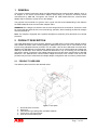
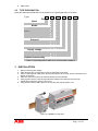
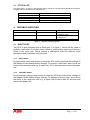
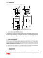
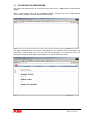
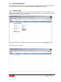
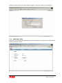
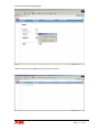
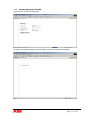
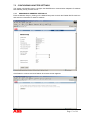
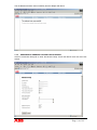
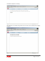
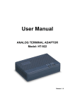
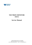
Ethernet
Communication
Adapter
CEM 05000
User’s Manual
Rev B1
ABB AB
P.O. Box 1005
SE-611 29 NYKÖPING
Sweden
Tel: +46 - 155 295000
Fax: +46 - 155 288110
Page 1 of 18
Table of Contents
1
GENERAL ................................................................................................................3
2
PRODUCT DESCRIPTION ....................................................................................3
2.1
2.2
3
INSTALLATION......................................................................................................4
3.1
4
PRODUCT OVERVIEW............................................................................................3
TYPE DESIGNATION ..............................................................................................4
STATUS LED .......................................................................................................5
TROUBLE SHOOTING ..........................................................................................5
4.1
RESET PORT .........................................................................................................5
4.1.1
Soft reset .....................................................................................................5
4.1.2
Factory reset ...............................................................................................5
5
TECHNICAL DATA................................................................................................6
5.1
DIMENSIONS ........................................................................................................7
6
AUTOMATIC METER READING ........................................................................7
7
THE WEB SERVER ................................................................................................7
7.1
ACCESSING THE WEB SERVER ...............................................................................8
7.2
USER MANAGEMENT ...........................................................................................9
7.2.1
Adding a user ..............................................................................................9
7.2.2
Removing users .........................................................................................10
7.2.3
Configuring User Setting...........................................................................12
7.3
CONFIGURING ADAPTER SETTINGS .....................................................................13
7.3.1
Assigning IP-address statically..................................................................13
7.3.2
Assigning IP-address through DHCP-server. ............................................14
7.3.3
Timeout Configuration ..............................................................................16
8
ABBREVIATIONS AND ACRONYMS................................................................17
9
INDEX.....................................................................................................................18
© 2006-2007 by ABB AB. All rights reserved.
Trademarks
Microsoft, Internet Explorer, Windows, and Windows NT are registered trademarks of Microsoft Corporation.
Other brand and product names are registered trademarks or trademarks of their respective holders.
Page 2 of 18
1 GENERAL
This manual contains information about the CEM 05000 Ethernet communication adapter, which is
an adapter of the serial communication adapter (SCA) family for electronic electricity meters
manufactured by ABB AB. Throughout this manual the CEM 05000 Ethernet communication
adapter will be referred to as the SCA or the adapter.
The purpose of this manual is to give the user a good overview and understanding of the features
the CEM 05000 Ethernet communication adapter offers.
WARNING! The voltages connected to the SCA are dangerous and can be lethal. Therefore it must
be insured that the terminals are not touched during operation. When installing the SCA all voltages
must be switched off.
Note: The adapter is equipped with a positive temperature coefficient (PTC) thermistor for overload
protection.
2 PRODUCT DESCRIPTION
The CEM 05000 Ethernet communication adapter is an ABB serial communication adapter product
that enables automatic meter reading (AMR) of ABB electricity meter over a LAN-network or the
internet using standard Ethernet protocols TCP and UDP. Like all other ABB serial communication
adapters the ABB Ethernet communication adapter have the size of 2 DIN-modules and follows the
ABB’s pro M-standard, which defines mechanical dimensions, way of mounting (35 mm DIN-rail)
and design outlook. Furthermore the adapter follows and meets the safety requirements of DIN EN
50090-2-2. The ABB Ethernet communication adapter does also have a built-in web server that
provides easy access of meter data and simple adapter configuration with an ordinary web browser.
2.1
PRODUCT OVERVIEW
The different parts of the SCA are depicted below.
1.
2.
3.
4.
5.
Figure 1: SCA parts.
RJ-45 Ethernet connector.
Reset port.
Label with the type designation and MAC address.
Terminal for connecting power.
Infra-red communication port
Page 3 of 18
6. Status LED.
2.2
TYPE DESIGNATION
Below are tables with explanation for all positions in the type designation for the SCA.
Type
Pos
1
2
3
4
5
6-8
Basic
Serial Communication Adapters
C
Media
Power Line, Band A
A
Power Line, Band C
C
Ethernet
E
GSM/GPRS
G
RS 232
R
Twisted Pair
T
Protocol
LonWorks
L
M-Bus
M
0
Supply voltage
Powered by device
4
100 - 240 V
5
220 - 240 V
6
Optional functionality
No options
000
Table 1: Type designation of ABB Serial Communication Adapters.
3 INSTALLATION
1. Disconnect the power supply.
2. Strip the wires and connect them to the top terminals of the SCA.
3. Connect the Ethernet cable to the RJ-45 LAN interface of the SCA, which is located on the
bottom of the SCA.
4. Place the SCA to the left of the meter and snap it on the DIN-rail.
5. Verify that the SCA is correctly wired and the voltage is according to the technical
specification before the power is turned on.
6. Verify that the status LED is green to ensure link and that the power is on.
Figure 2: Installation of the SCA.
Page 4 of 18
3.1
STATUS LED
The status LED 1. of figure 1. indicates the state of the SCA. The chart below describes the state of
the SCA and how the status LED indicates this.
Status LED
Green
Flashing Green
Off
Red
SCA Status
Link has been established and OK.
Transferring data.
No link established.
Fatal Error.
Table 2: Table over the status LED indication.
4 TROUBLE SHOOTING
Status LED
Off
Cause
No link.
Off
No power to SCA.
Red
Fatal error.
Corrective actions
Please check the connection of
the network cable.
Please check the connection of
the power line.
Please contact your dealer.
Table 3: Trouble shooting guide.
4.1
RESET PORT
The SCA is also equipped with a Reset port 7 in figure 1. which can be used to
perform a soft reset or a factory reset. Reset is performed by short circuit the two
holes in the reset port. Below follows a description over the different reset
procedures and how these are performed.
4.1.1
SOFT RESET
By performing a soft reset means to reset the SCA without restoring the settings of
the adapter to the default factory settings. To perform a soft reset, short circuit the
holes in the reset port with e.g. a paper clip, for 10 seconds and remove the paper
clip.
4.1.2
FACTORY RESET
By performing a factory reset means to reset the SCA and restore the settings of
the adapter to the default factory settings. To perform a factory reset, short circuit
the holes in the reset port with e.g. a paper clip for more than 40 seconds and
remove the paper clip.
Page 5 of 18
5 TECHNICAL DATA
Network Protocol and Standards Compatibility
Data protocols:
TCP/IP, UDP, DHCP.
Power Supply
Nominal voltage:
Voltage range:
Frequency:
Power consumption:
Terminal wire area:
Recommended tightening torque:
100-240 V AC
-20 % to +15 % of nominal voltage.
50/60 Hz ± 5 %
0.80 VA at 230 V AC, 50 Hz.
0 – 2.5 mm²
0.5 Nm
Mechanical Data
Casing material:
Protection class:
Weight:
Polyamide
IP 20
90 g
Environmental Specifications
Operating temperature range:
Storage temperature range:
Humidity:
-40 °C to +55 °C
-40 °C to +70 °C
75% yearly average
95% on 30 days/year
Interface Specifications
LAN:
Connection interface:
10BASE-T, 10 Mbps
RJ-45
Standards
Safety:
DIN EN 50090-2-2.
Page 6 of 18
5.1
DIMENSIONS
The physical dimensions of the SCA are displayed below.
Power
1
4
ABB IR
Interface
Ethernet
D51
Figure 3: The physical dimensions of the SCA.
6 AUTOMATIC METER READING
The ABB Ethernet communication adapter provides Automatic Meter Reading (AMR) using M-Bus
protocol over UDP or TCP through a LAN-network or the internet. This is done transparently without
altering the original M-Bus telegrams. Please note that the shortest time between readouts is
different depending on the type of the electricity meter; please refer to the User’s Manual of the
electricity meter for more information.
7 THE WEB SERVER
Besides providing communication with an AMR-system the ABB Ethernet communication adapter
does also have a built-in Web-server that enables static meter reading over a LAN-network or
internet using an ordinary web browser. The web-server provides an easy interface to configure the
settings of the adapter and its users and privileges. The adapter’s IP-address can be assign either
statically or dynamically by a DHCP-server.
All quantities that can be readout by using the M-Bus protocol on the AMR part of the adapter can
be readout on the built-in web server except the features that are listed below.
·
·
·
Load Profile Values.
Maximum Demand.
Voltage Event Log.
Please refer to the User’s Manual of the electricity meter for more information of what quantities
that can be readout depending on the type of electricity meter.
Page 7 of 18
7.1
ACCESSING THE WEB SERVER
This section will describe how to access the built-in web server in ABB Ethernet communication
adapter.
Open a web browser and type the IP-address (default: 192.168.1.10) of the ABB Ethernet
communication adapter in the web browsers address field.
The page will appear like the one below. The quantities of the electricity meter are located in the
main frame of the browser and in the left frame are all telegrams in the electricity meter. The
quantities that appear will be different depending on the model of electricity meter.
Page 8 of 18
7.2
USER MANAGEMENT
This section will deal with the user management feature in ABB Ethernet communication adapter. It
will discuss how to add and remove users and setting their privileges and settings.
7.2.1
ADDING A USER
Enter the User Management menu and click then on the Add User tab. Add user by filling in the
fields below and submit. Please note that once the password is set it is non-recoverable, therefore
save the password and keep it in a safe place.
User data received will appear.
Page 9 of 18
Restart the web browser and a login window will appear. Login with username and password.
7.2.2
REMOVING USERS
Click on the User Management tab and then use the arrow buttons to scroll to the user that shall be
removed. Click then remove.
Page 10 of 18
Click OK when below dialog appear.
When the below screen appear the user has been removed.
Page 11 of 18
7.2.3
CONFIGURING USER SETTING
Login and click on the My Settings tab.
Change to the preferred settings and click submit. And the screen below will appear.
Page 12 of 18
7.3
CONFIGURING ADAPTER SETTINGS
This section will describe how to configure the ABB Ethernet communication adapter’s IP-address
both statically and by a DHCP-server.
7.3.1
ASSIGNING IP-ADDRESS STATICALLY
Enter the Module Setup by clicking on the Module Setup tab. Uncheck the Enable DHCP check box
and enter the information for static IP-address.
Click Submit to continue and click Reboot when below screen appears.
Page 13 of 18
The IP-address has been set successfully and the adapter will reboot
7.3.2
ASSIGNING IP-ADDRESS THROUGH DHCP-SERVER.
Click on the Module Setup tab to enter the Module Setup. Check the DHCP check box and click
submit.
Page 14 of 18
Click Reboot to adopt the new settings.
The configuration of IP-address through DHCP server has been set successfully and the adapter
will reboot.
Page 15 of 18
7.3.3
TIMEOUT CONFIGURATION
There are two kinds of timeouts that can be configured on the Ethernet
communication adapters, AMR and Web timeout. These timeouts determines how
long time the AMR or the Web server will have exclusive right to access the
electricity meter. Below follows an explanation of these and how they are
configured.
AMR Timeout
The AMR timeout is the time in which the AMR system has the exclusive right to
access the electricity meter. This means that the web server will not be able to
access the electricity meter until the AMR timeout has timed out after an AMR
access of the adapter. By default the AMR timeout is set to 60 seconds.
Example: if the AMR timeout is set to 60 seconds it means that the web server will
only be able to access the values of the electricity meter 60 seconds after a
performed AMR access of the electricity meter.
Web Timeout
The Web timeout is the time in which the web server will have the exclusive right to
access the electricity meter. This means that the AMR system will not be able to
access the electricity meter until the Web timeout has timed out after an access
using the web server.
This parameter is set according to the prevailing network environment and should
not to be set too long as the Ethernet adapter will block the AMR system to access
the electricity meter until the Web timeout has timed out. On the contrary by setting
this parameter too short the AMR system can cut in and access the electricity
meter before the web server has accomplished to do all it’s readout of the meter.
This will lead to the consequence that the communication on the network will time
out and the web server will not be able to read all the pages from the electricity
meter. Therefore the setting of the Web timeout should be set small enough to be
able read all the pages of the meter and set large enough to keep the network
communication alive. By default the Web timeout is set to 120 seconds and should
be increased if the Ethernet adapter is connected to a slow network.
Example: if the Web timeout is set to 120 seconds it means that the AMR system
will only be able to access the values of the electricity meter 120 seconds after an
access of the web server.
Page 16 of 18
8 ABBREVIATIONS AND ACRONYMS
10BASE-T
IEEE 802.3 specification for 10 Mbps Ethernet over twisted pair wiring.
DHCP
Dynamic Host Configuration Protocol, An Ethernet protocol specifying how a
centralized DHCP server can assign network configuration information to multiple
DHCP clients. The assigned information includes IP addresses, DNS addresses,
and gateway (router) addresses.
IP
Internet Protocol, The main internetworking protocol used in the Internet. Used in
conjunction with the Transfer Control Protocol (TCP) to form TCP/IP.
IP Address
A four-byte number uniquely defining each host on the Internet. Ranges of
addresses are assigned by Internic, an organization formed for this purpose.
Usually written in dotted-decimal notation with periods separating the bytes (for
example, 192.168.1.10).
LAN
Local area network. A communications network serving users within a limited area,
such as one floor of a building. A LAN typically connects multiple personal
computers and shared network devices such as storage and printers. Although
many technologies exist to implement a LAN, Ethernet is the most common for
connecting personal computers.
MAC address Media Access Control address. A unique 48-bit hardware address assigned to
every Ethernet node. Usually written in the form 00:03:47:D8:AE:3A.
Mbps
Megabits per second.
Netmask
A number that explains which part of an IP address comprises the network address
and which part is the host address on that network. It can be expressed in dotteddecimal notation or as a number appended to the IP address. For example, a 28-bit
mask starting from the MSB can be shown as 255.255.255.192 or as /28 appended
to the IP address.
UTP
Unshielded twisted pair. The cable used by 10BASE-T and 100BASE-Tx Ethernet
networks.
Page 17 of 18
9 INDEX
A
Accessing the web server....................... 8
Adding a user ........................................ 9
AMR timeout ..................................... 16
Assigning IP-address statically. ........... 13
Assigning IP-address through DHCPserver. ............................................. 14
Automatic meter reading, AMR............. 7
C
Configuring Adapter Settings .............. 13
Configuring User Setting..................... 12
My Settings ..........................................12
O
Overload protection ...............................3
R
Removing users ...................................10
Reset port ............................................5
Reset Port ..............................................3
RJ-45 Ethernet connector.......................3
S
DHCP ................................................. 14
SCA parts ..............................................3
Soft reset..............................................5
Standards ...............................................6
Status LED ........................................3, 5
F
T
Facotry reset ....................................... 5
Humidity............................................... 6
Temperature...........................................6
Terminal for connecting power ..............3
Timeout configuration .......................16
Type designation....................................4
I
U
Infra-red ................................................ 3
Installation ............................................ 4
IP-address ....................................... 8, 13
User Management............................9, 10
D
H
M
Module Setup ................................ 13, 14
W
Web server.............................................7
Web timeout.......................................16
Page 18 of 18