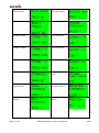
1
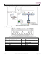
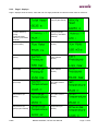
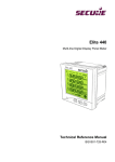
Real time Pump/ Hydro-Turbine/ Blower Performance Monitoring with
Censeo
User Manual
BGX501-806-R02
Copyright © 2013, SIHPL
Page 2 of 20
BGX501-806-R02, Censeo User Manual
Public
Table of Contents
1
Important ..................................................................................................................................... 4
2
Precautions and Safety Practices .............................................................................................. 4
3
Introduction ................................................................................................................................. 5
4
About Censeo .............................................................................................................................. 5
4.1
General Specifications .................................................................................................................................. 5
4.1.1
Electrical ......................................................................................................................................... 5
4.1.2
Communication with PC and Power Meter ..................................................................................... 5
4.1.3
Pump/ Hydro-Turbine Flow Measurement (Variant dependent) ..................................................... 6
4.1.4
Blower Flow Measurement (Variant dependent) ............................................................................ 6
4.1.5
Mechanical ...................................................................................................................................... 6
4.1.6
Environmental ................................................................................................................................. 6
4.1.7
Compliances ................................................................................................................................... 6
4.2
Basic System Block Diagram for Pump Flow Measurement ......................................................................... 7
4.3
Connection Diagram ...................................................................................................................................... 7
4.4
Parts Description ........................................................................................................................................... 8
5
Firmware Features ...................................................................................................................... 9
5.1
Principle of Operation .................................................................................................................................... 9
5.2
Benefits ........................................................................................................................................................ 10
5.3
What does Censeo Measure ....................................................................................................................... 10
5.4
Input and output........................................................................................................................................... 10
5.5
Keys ............................................................................................................................................................. 11
5.6
Display ......................................................................................................................................................... 12
5.6.1
Meter Information displays ............................................................................................................ 12
5.6.2
Page 1 displays............................................................................................................................. 13
5.6.3
Page 2 display – pump/ hydro-turbine/ blower parameters .......................................................... 15
5.6.4
Page 3 display – motor/ generator parameters ............................................................................ 16
5.6.5
Page 4 displays – alarm parameters ............................................................................................ 17
5.7
Cumulative Flow .......................................................................................................................................... 17
5.8
Cumulative Energy ...................................................................................................................................... 17
5.9
Communication............................................................................................................................................ 18
5.10 Alarms and Events ...................................................................................................................................... 18
5.11 Relays .......................................................................................................................................................... 18
5.12 Data Storage ............................................................................................................................................... 18
5.13 Time Management....................................................................................................................................... 18
5.14 Security ........................................................................................................................................................ 18
5.15 Transactions ................................................................................................................................................ 18
6
Frequentlty Asked Questions (FAQs) ...................................................................................... 19
Public
BGX501-806-R02, Censeo User Manual
Page 3 of 20
1 Important
1. As a result of our continuous efforts to improve our products, the specifications mentioned in this manual
may be subject to change. Therefore the availability of features may depend on the product variant.
2. The specifications and features listed in this manual were correct when this document was released but
may be subject to change and should be considered to be definitive. Please refer any queries to our sales
team.
3. No part of this manual or its contents may be published, distributed, scanned or copied, in electronic form or
otherwise, without prior written consent of Secure Meters Ltd.
4. While we have made every effort to minimise errors, some may exist. We request feedback from users in
this regard and undertake to correct such errors wherever possible.
5. Secure Meters Ltd. reserves the right to alter the features or specifications mentioned in this document
without prior notice.
6. Please direct queries on our products or services to our sales team.
7. In most countries, electrical installations must comply with one or more sets of regulations issued by
national authorities or by recognized local or international bodies. Such regulations must be adhered to,
even if they are not referred to directly in this document.
8. We conduct rigorous testing during the design and manufacture of our products to ensure that they comply
with appropriate standards.
9. Secure Meters Ltd. assumes no responsibility for damage arising from misuse of our products such as, but
not limited to, the following:
•
Incomplete or incorrect installation or maintenance
•
Connection to incorrect voltage sources
•
Damaged insulation on connecting cables
•
Contact with hazardous substances
•
Immersion in water or any other liquid
•
Handling by unauthorized persons
•
Handling by inebriated, intoxicated or mentally unbalanced persons
2 Precautions and Safety Practices
1. Censeo needs mains supply to function, and may need to be installed in electrically live surroundings. To
minimise the risk of electrical shock, stay away from loose or exposed electrical connections. If there is
loose or exposed electrical wiring near the installation site, initiate appropriate preventive measures.
2. Ensure proper protection from abnormal power supply with the help of fuse/ relay/ circuit breaker is
provided.
3. Keep the meter away from fire, corrosive chemicals, and fumes thereof, rain and direct, prolonged exposure
to water.
4. The product may be damaged, either in part or otherwise, if it falls from a height or subjected to a heavy
weight.
5. It is recommended to immediately cut off the power supply upon occurrence of any fault within the product.
6. Secure Meters System recommends carrying out regular installation checks, especially when the product is
installed at locations posing higher risk of degradation or corrosion – such as under direct, strong sunlight,
areas with high ambient temperature and little ventilation, areas near heat sources like a furnace, areas
near sea or a water body, areas where the meter is regularly exposed to chemical fumes, etc.
7. The electrical and mechanical installation of electronic equipments at a site requires an adequate
understanding of all governing rules and regulations.
Page 4 of 20
BGX501-806-R02, Censeo User Manual
Public
3 Introduction
Censeo product family is the latest offering from Secure Meters aimed towards measuring and monitoring
critical pump/ hydro-turbine/ blower performance parameters with high accuracy in commercial and industrial
pump/ hydro-turbine/ blower installations.
Censeo –
•
Monitors and displays pump/ hydro-turbine/ blower operating parameters in real time with the help
of temperature and pressure sensors and a power meter.
It measures suction/ inlet pressure, discharge/ outlet pressure, suction/ inlet temperature and
differential temperature; and reads motor/ generator parameters such as voltage, current, drive
power/ generated power, power factor and frequency through interfaced power meter to calculate
the pump/ hydro-turbine/ blower performance parameters such as efficiency, flow rate and total
head. These parameters can also be read by a computer over RS485.
•
Is run time configurable through a software tool called Pump Test 9. This software is used to
configure essential information and parameters such as Censeo time, communication, displays,
historical data, analogue outputs, alarms and relays. Besides configuring Censeo, Pump Test 9 is
also used for viewing online data, reading historical data, alarms logged and transactions from
Censeo. (refer to Pump Test 9 help for details)
4 About Censeo
4.1
General Specifications
4.1.1
Electrical
Product type
Single phase, three wire with inputs for MODBUS signals
Product Class
Class A
SMPS
110-230 V AC/DC
Frequency
50/60 Hz
Tolerable frequency
variation
± 5%
Internal relays
Contact rating 230 V AC, 2 A
Sensor inputs*
Suction/ Inlet and
Discharge/ Outlet
pressure
3 wire Analogue 4-20 mA / 4 wire Analogue 1-5 V probe
as specified by manufacturer
Suction/ Inlet and
Discharge/ Outlet
temperature
3 wire Analogue probe as specified by manufacturer
*According to variant
4.1.2
Communication with PC and Power Meter
Meter configuration through PC
RS232 communication through PACT port using Pump Test 9
Pump/ Hydro-Turbine/ Blower
monitoring on PC
Two wire RS485 based communication with PC using MPM-Watch
Power meter
Power meter supporting 32 bit floating Modbus protocol on RS-485
Input / Output terminals*
Four fixed Analogue Inputs 1-5 V / 4-20 mA
Four configurable Analogue input / output 1-5 V / 4-20 mA
*According to variant
Public
BGX501-806-R02, Censeo User Manual
Page 5 of 20
4.1.3
Pump/ Hydro-Turbine Flow Measurement (Variant dependent)
Accuracy class
4.1.4
2 mK*
Fluid temperature
0.2 °C
Pressure
0.25% of full scale pressure
Efficiency
0.5 %
Flow
1%
Max. pressure head
300 bar
Max. fluid outlet
temperature
80 °C, with a maximum variation of 8 °C between suction/ inlet and
discharge/ outlet.
Blower Flow Measurement (Variant dependent)
Accuracy class
4.1.5
Differential
temperature
Differential
temperature
150 mK
Air temperature
0.2 °C
Pressure
0.25% of full scale pressure
Efficiency
1%
Flow
1%
Max. pressure head
5 bar
Max. air outlet
temperature
150 °C, with a maximum variation of 120 °C between inlet and outlet.
Mechanical
Dimensions (mm)
144 (H) x 144 (W) x 172 (D)
Weight
~1.200 kg
Mounting type
Projection and Panel type
Housing material
Fire Retardant Poly-Carbonate (FR-PC)
Front & back cover
Fire Retardant Poly-Carbonate (FR-PC)
Glands for wire insertion Six (three PG9 and three PG13.5) glands provided at the bottom
Wall Mounting holes
Four (2 oblong and 2 circular)
Wall Mounting clamp
Available on the rear cover
Display
81 x 53 mm, 128 x 80 pixels LCD display with green backlight
Keys
4 – left, right, up and down
4.1.6
Environmental
Operating temperature
0 ºC to 70 ºC
Storage temperature
-10 ºC to 70 ºC
Ingress protection
IP54
Max. tolerable humidity
Up to 95% non-condensing
4.1.7
Compliances
Electrical
Page 6 of 20
IEC61326-1, CISPR22, BS:EN 61010-1
BGX501-806-R02, Censeo User Manual
Public
Mechanical
4.2
IEC62052-21, IEC695-2-1, IEC68-2-27,IEC68-2-6, IEC60529
Basic System Block Diagram for Pump Flow Measurement
Figure 1: Performance monitoring system
4.3
Connection Diagram
Figure 2: Connection Diagram (as pasted on the underside of rear cover of Censeo)
INDEX
R1, R2
Two wire outputs for relays
Tdi
Discharge/ Outlet Temperature Sensor
(Red)
Psi
Suction/ Inlet Pressure Sensor
TX1, RX1
Transmit and Receive lines for PC over
RS485
Pdi
Discharge/ Outlet Pressure Sensor
TX2, RX2
Transmit and Receive lines for Power
Meters over RS485
Tsi
Suction/ Inlet Temperature Sensor
(Blue)
IO1-4
Analogue two-wire Input / Output
terminals
E
Earth for shielding
A1-4
Fixed analogue inputs
G
Ground
15V
Input 15 V DC supply to sensors
N
Neutral/ Negative
V
5 V DC supply to Tsi
P
Phase/ Positive
-5 V
- 5 V DC supply to Tdi
Note: Pin details may vary with variants. Interpret the diagram and table above for the right variant.
Public
BGX501-806-R02, Censeo User Manual
Page 7 of 20
4.4
Parts Description
Figure 3: Censeo Parts
Figure 4: Censeo Connections
The various parts as shown in the diagrams above are described as under –
1. Dot matrix LCD display: Censeo display is a 128 x 80 pixels dot matrix LCD type display with backlight.
2. PACT port: Available at the bottom left corner of the front plate, the PACT port is used to configure the
meter on demand through RS232 communication from a computer with the help of appropriate
software.
3. Front plate: Made of fire resistant poly carbonate material, the front plate is opaque and is covered with
an additional transparent plate. It accommodates a four button keypad and a PACT port. The front plate
also accommodates the rating plate as shown here.
Page 8 of 20
BGX501-806-R02, Censeo User Manual
Public
Figure 5: Decal and Front Plate of Censeo
4. Buttons: A keypad containing four orthogonal buttons is available for various functions.
5. Mounting Holes: Four mounting holes are available at the rear corners of the meter casing to mount the
Censeo on a wall.
6. Clamp screw: These screws are used to fasten side mounting clamps for panel installation. This will
arrest the horizontal movement of Censeo through the panel while installation.
7. Bottom glands: These glands are basically an entry for the supply and communication cables at the
bottom of the Censeo.
8. Side mounting clamp: A couple of side mounting clamps are available to mount the Censeo on a panel.
9. Pressure and temperature sensor terminals: These terminals are used to connect four types of sensor
inputs – suction/ inlet pressure, discharge/ outlet pressure, suction/ inlet temperature and discharge/
outlet temperature.
10. RS485 PC communication terminals: These terminals are used for communicating continuously with a
computer for real-time pump/ hydro-turbine/ blower monitoring, flow and efficiency calculations.
11. Relay terminals: These outputs from relays inside Censeo are used to drive external alarm / control
circuits towards various purposes. The relays retain their state until driven again by Censeo, or the next
power cycle.
12. Power supply terminals: These terminals are used to power up the Censeo with a single phase AC or
DC supply.
13. RS485 power meter communication terminals: These terminals are used to feed real-time RS485 inputs
from external electronic wattmeters or power meters which measure the power drawn/ generated by the
pump/ hydro-turbine/ blower in real time.
14. Terminals for analogue inputs / outputs: If available, these terminals are used to either feed extra
signals from sensors or to transmit extra signals outside from the Censeo.
5 Firmware Features
5.1
Principle of Operation
Censeo employs the thermodynamic method of calculating work done on the pumped fluid by measuring
differences between temperature and pressure at suction/ inlet and discharge/ outlet ends through highly
precise temperature probes and pressure transducers. The efficiency calculation done by this method is based
on calculating losses. In a typical pump/ hydro-turbine system the main losses occur are temperature rise,
noise, vibration. Almost 98% of losses constitute the temperature rise.
While pumping/ rotating any fluid, mechanical work is done on the liquid which raises its temperature
measurably. Moreover, because of the significant mechanical effort applied on the fluid, discharge/ outlet
pressure is always slightly higher than the suction/ inlet pressure (this is inverse for hydro-turbine however).
Thus, a little energy is dissipated as heat which gets absorbed by the fluid and mechanical vibrations of the
pump/ hydro-turbine setup.
Through highly precise electronic probes and transducers, it is possible to measure such differential changes in
temperature and pressure. Once accurate numerical data is available, actual losses in the system can be
calculated using thermodynamic equations. When input/ output electrical power to/ from the motor/ generator
Public
BGX501-806-R02, Censeo User Manual
Page 9 of 20
and all losses for the pump/ hydro-turbine setup are known, pump/ hydro-turbine efficiency and flow rate can be
easily determined using fluid constants such as specific gravity, isothermal coefficients, specific heat, etc.
Censeo employs the polytropic method for calculating the blower efficiency.
5.2
Benefits
The thermodynamic method works well for pumps, with heads as low as 10 metres, as well as hydro turbines.
Not only is the achieved accuracy of measurement better than those obtained by conventional methods, it easily
exceeds 99%.
Availability of accurate, real time numerical data can be read by a computer and used to plot performance
graphs for a pump. Arriving at the most optimum point of operation thus becomes possible.
Because pump/ hydro-turbine graphs are available to the operator, it is possible to schedule the daily operation
as well as pump/ hydro-turbine service and repair. Real time condition monitoring of the pump/ hydro-turbine
helps in its correct operation and enhancing its life. Correct operation of the pump/ hydro-turbine leads to lesser
maintenance and pump/ hydro-turbine down time.
Because of electronic measurements and digital data, it becomes easy to generate reports with a computer and
communicate the same over various communication technologies and to interface with complex Control And
Data Acquisition (CADA) systems.
5.3
What does Censeo Measure
Censeo accepts inputs from two temperature probes, two pressure transducers and a power meter to calculate
pump/ hydro-turbine/ blower flow performance parameters and flow rate.
While temperature and pressure analogue inputs are fed through individual probes, the power meter input is
always on RS485.
Censeo measurements are available in real time for effective monitoring and generating highly accurate pump/
hydro-turbine/ blower performance graphs. (Refer section Basic System Block Diagram for Pump Flow
Measurement)
5.4
Input and output
In addition to temperature, pressure and power inputs, Censeo can also accept eight analogue software
configurable inputs, either 4-20 mA or 1-5 V, which can be used towards various computational purposes.
The possible parameter assignments to these inputs, with their available units, are as follows:
S.No.
Description
Units
S. No.
Description
Celsius (°C)
Fahrenheit (F)
1
Temperature
Level
Inch
metre
Voltage
6
Current
7
Power
millibar
8
Frequency
Hertz (Hz)
pounds per square inch
(psi)
9
Vibration
Hertz (Hz)
centimetre
10
Speed
rpm
inch
11
Efficiency
percentage
metre
12
Absolute humidity
Percentage
MegaPascal (MPa)
bar
Page 10 of 20
4
5
kiloPascal (kPa)
Pressure
centimetre
milli-Kelvin (mK)
Pascal (Pa)
2
Units
BGX501-806-R02, Censeo User Manual
Volts
Amperes
milliAmpere (mA)
Watt (W)
kiloWatt (kW)
Public
cubic metres per second
(m3/sec)
13
gram per cubic metre
(g/m3)
Density
kilogram per cubic metre
(kg/m3)
litre per second (l/sec)
Volumetric flow
rate
3
cubic metres per hour
(m3/hr)
gallons per day (gal/day) 14
Other
NA
million litres per day
(Ml/day)
Table 1: Available software configurable parameters in Censeo for analogue inputs with units
The possible parameter assignments for Censeo outputs are as follows:
S. No.
Description
S. No.
Description
1.
Efficiency (Pump / Hydro-Turbine /
Blower)
2.
Flow Rate
3.
Total Head
4.
Drive Power/ Generated Power
5.
Overall Efficiency
6.
Discharge Pressure/ Outlet Pressure
7.
Suction Pressure/ Inlet Pressure
8.
Velocity Head
9.
Suction Temperature/ Inlet
Temperature
10.
Differential Temperature
11.
Voltage R-Phase
12.
Voltage Y-Phase
13.
Voltage B-Phase
14.
Current R-Phase
15.
Current Y-Phase
16.
Current B-Phase
17.
Frequency
18.
Average Power Factor
19.
Analogue Input 1
20.
Analogue Input 2
21.
Analogue Input 3
22.
Analogue Input 4
23.
Analogue Input 5
24.
Analogue Input 6
25.
Analogue Input 7
26.
Analogue Input 8
Table 2: Available software configurable parameters in Censeo for analogue outputs
5.5
Keys
The four keys available on Censeo are used for the following functions:
Key
Public
Function
Description
Key press
next
When pressed once, the display scrolls to the next one
available in the sequence.
Short
previous
When pressed once, the display scrolls to the previous one
available in the sequence.
Short
up
When pressed once, the display scrolls to the next display
page available in the sequence.
Short
down
When pressed once, the display scrolls to the previous
display page available in the sequence.
Short
Reset
display
When these buttons are pressed simultaneously for 5
seconds, Censeo reset the display page to show first-page,
first-display.
Long (5 sec)
BGX501-806-R02, Censeo User Manual
Page 11 of 20
scroll lock
When these buttons are pressed simultaneously for 5
seconds, Censeo locks the current display shown and stops
scrolling the display.
Long (5 sec)
Meter Info
When these buttons are pressed simultaneously for 5
seconds, Censeo displays meter information.
Long (5 sec)
Table 3: Available key functions in Censeo
5.6
Display
Censeo supports a maximum of 4 display pages and page 1 can show a maximum of 10 displays; each page 2
and page 3 can show a maximum of 4 parameters; page 4 can show a maximum of 2 alarm information.
Displays for Censeo are software configurable through Pump Test 9. Each key press turns the backlight on for
10 seconds, and the display reverts to the first page if no key is pressed for 30 seconds.
Each page has a defined type of displays as under –
Page
Remarks
1
This page is set up for auto scroll by default. While only one parameter is displayed at a time,
the maximum configurable auto-scroll time is 240 seconds. Up to 10 displays can be configured
for this page, and auto scroll can be stopped at desired display as shown in the Table 3.
2, 3
These pages are not set up for auto scroll by default. Up to 4 parameters can be defined for
pages 2 and 3.
4
This page is used only for alarm displays. Up to 8 alarms can be configured for parameters
shown in Table 2 out of which only 2 can be shown.
Table 4: Available display pages in Censeo
Upon every power up or pump/ hydro-turbine/ blower start, ‘dT stabilizing’ display is shown when the efficiency
calculation method is Thermodynamic, Thermodynamic method in combination of any other method or
polytropic, until dT gets stabilized. This display lasts for approximately 2 minutes if the Censeo and pump/
hydro-turbine/ blower are powered on.
If the efficiency calculation method is Lookup, Conventional or combination of Lookup and Conventional
method, then display will show ‘Stabilizing’.
5.6.1
Meter Information displays
Meter information displays last only for 5 seconds and can be activated as shown in Table 3. First page in meter
information displays shows the serial number and firmware version; second page in meter information displays
shows the power on-off count, baud rate of power meter communication port, baud rate of RS485
communication port and baud rate of the optical port.
Page 12 of 20
BGX501-806-R02, Censeo User Manual
Public
5.6.2
Page 1 displays
Page 1 displays show the name, value and unit of a single parameter at a time as shown here for reference.
Total head
Velocity head (for
pump/ hydro-turbine)
Pump/ HydroTurbine efficiency
(using
Thermodynamic
efficiency calculation
method)
Blower efficiency
(using Polytropic
efficiency calculation
method)
Flow rate (for pump/
hydro-turbine)
Flow rate (for
blower)
Suction pressure (for
pump)
Inlet pressure (for
hydro-turbine/
blower)
Discharge pressure
(for pump)
Outlet pressure (for
hydro-turbine/
blower)
Suction temperature
(for pump)
Inlet temperature
(for hydro-turbine/
blower)
Discharge
temperature (for
pump)
Outlet temperature
(for hydro-turbine/
blower)
Differential
temperature (for
pump/ hydro-turbine)
Differential
temperature (for
blower)
Public
BGX501-806-R02, Censeo User Manual
Page 13 of 20
Drive power (for
pump/ blower)
Generated Power
(for hydro-turbine)
Shaft Power
Overall efficiency
Voltage R-Phase
Current R-Phase
Voltage Y-Phase
Current Y-Phase
Voltage B-Phase
Current B-Phase
Frequency
Average Power
Factor
Motor Efficiency (for
pump/ blower)
Generator Efficiency
(for hydro-turbine)
Drive Efficiency (for
blower)
Mass Flow Rate (for
blower)
Page 14 of 20
BGX501-806-R02, Censeo User Manual
Public
Analogue inputs (Sample displays with units)
Analogue input 2
Analogue input 1
General Parameters
Current Date
Current Time
Hours Run
Key Performance
Index
5.6.3
Page 2 display – pump/ hydro-turbine/ blower parameters
Page 2 is used to show the values of pump/ hydro-turbine/ blower parameters. Up to 4 parameters can be
configured through software and these are shown as mentioned.
The available pump parameters for Page 2 display are as follows:
Pump Parameter Name
Display
Efficiency
EF
Flow Rate
QP
Total Head
TH
Overall Efficiency
OE
Discharge Pressure
PD
Suction Pressure
PS
Velocity Head
VH
Suction Temperature
TW
Differential Temperature
DT
Discharge Temperature
DW
Table 5: Available Pump Parameters for Page 2 display in Censeo
The available hydro-turbine parameters for Page 2 display are as follows:
Hydro-Turbine Parameter Name
Public
Display
Efficiency
EF
Flow Rate
QP
BGX501-806-R02, Censeo User Manual
Page 15 of 20
Total Head
TH
Overall Efficiency
OE
Inlet Pressure
PI
Outlet Pressure
PO
Velocity Head
VH
Inlet Temperature
TI
Differential Temperature
DT
Outlet Temperature
TO
Table 6: Available Hydro-Turbine Parameters for Page 2 display in Censeo
The available blower parameters for Page 2 display are as follows:
Blower Parameter Name
Display
Polytropic Efficiency
EF
Volumetric Flow Rate
QP
Mass Flow Rate
QM
Overall Efficiency
OE
Inlet Pressure
PI
Outlet Pressure
PO
Inlet Temperature
TI
Differential Temperature
DT
Total Head
TH
Table 7: Available Blower Parameters for Page 2 display in Censeo
5.6.4
Page 3 display – motor/ generator parameters
Page 3 is used to show the values of motor/ generator parameters. Up to 4 parameters can be configured
through software and these are shown as mentioned.
The available parameters for Page 3 display are as follows:
Page 16 of 20
Parameter Name
Display
Voltage R phase
VR
Voltage Y phase
VY
Voltage B phase
VB
Current R phase
IR
Current Y phase
IY
Current B phase
IB
Drive Power/ Generated Power
PWR
Average Power Factor
PF
BGX501-806-R02, Censeo User Manual
Public
Frequency
FQ
Motor Efficiency (for pump/ blower)
EFm
Generator Efficiency (for hydro-turbine)
EFg
Shaft Power
SP
Drive Efficiency (for blower)
Efd
Table 8: Available Parameters for Page 3 display in Censeo
5.6.5
Page 4 displays – alarm parameters
Page 4 is used to show alarm parameters. Up to 2 alarms can be configured through software for display and in
case the defined parameter limits are crossed, these are shown as mentioned. Otherwise the display remains
blank.
Besides date and time, this display is interpreted as follows:
O, R
Occurrence & restoration with date and
time
AL1, AL2
Alarm 1, Alarm 2
dT, Eff
Parameters for which alarms are
configured
BL
Below limit
AL
Above limit
OR
Out of range
IR
In range
Table 9: Index for Alarm page in Censeo
5.7
Cumulative Flow
Cumulative flow for pump/ hydro-turbine/ blower is calculated by the connected Censeo which can be read and
displayed (in ML) on page 1 display as shown below.
In case of any exceptional conditions such as communication failure with the power meter, sensors
disconnected, Censeo will not be able to calculate the Cumulative Flow and hence will display the last correct
value as calculated by Censeo. The time stamps are not logged for the duration in which Censeo is unable to
calculate cumulative flow.
5.8
Cumulative Energy
Censeo reads the cumulative energy for pump/ hydro-turbine/ blower from the power meter connected over
Modbus, which can be read and displayed (in kWh) on page 1 display as shown below. The refresh rate of
cumulative energy value is 1 minute.
Public
BGX501-806-R02, Censeo User Manual
Page 17 of 20
Cumulative energy will be displayed as ‘NOT AVAILABLE’ either on communication failure with the power meter
or if power meter setting is set to ‘Fixed’ or ‘Analogue’.
5.9
Communication
Censeo communicates through three channels – one is used for communicating with power meter while the
remaining two are used to communicate with a PC. Of these two channels, one is used for configuring Censeo
on PACT while the other is used to transfer real time pump/ hydro-turbine/ blower performance data on RS485
to the software on the computer.
Censeo communicates with the power meter on RS485 through wired connection. Communication with a power
meter including the baud rate can be configured through Pump Test 9.
5.10 Alarms and Events
Up to eight alarms can be configured for parameters available in Table 2. For each alarm, a maximum of 20
events can be logged compartment-wise in a rollover mode – that makes a total of 160 events. Note that display
and relay indication for alarms would only be configurable through respective display and relay sections in the
software.
Note: The alarm persistence time for pump/ hydro-turbine/ blower parameters like differential temperature, flow
rate, suction/ inlet temperature, efficiency etc. may vary from persistence time configured by Pump Test9 based
on ‘filter value’ (i.e. averaging period) and the ‘parameter value’s difference with the defined limit at the time of
event’, this is in view of slow varying nature of thermal parameters like temperature in pump/ hydro-turbine/
blower and to avoid false alarms.
5.11 Relays
Censeo can drive two latching relays towards control applications. Relays can be used to either indicate
occurrence of an alarm or to schedule the operation of a pump/ hydro-turbine/ blower.
5.12 Data Storage
Up to 600 parameter days of data with 15 minute DIP can be stored in Censeo memory. The parameters logged
will be configurable, and a maximum of 15 parameters can be selected.
5.13 Time Management
Censeo maintains time with a resolution of one second. Time and date in Censeo can be configured through
Pump Test 9.
5.14 Security
Information from, and transactions with, Censeo are secured with the help of keys.
Pump Test 9 needs to know information related to keys in order to communicate with Censeo. The customer
specific add-on keys (if provided along with the product key) must be added into Pump Test 9 software. (refer to
Pump Test 9 help for details)
5.15 Transactions
Besides collecting and sending out pump/ hydro-turbine/ blower performance data, Censeo also supports
transactions such as time set, configuration download, reset transactions, clearing away historical data sets,
reconfiguration of calibration constants, display configuration, etc.
Censeo maintains a record of last 100 transactions with time stamp in a rollover manner.
Page 18 of 20
BGX501-806-R02, Censeo User Manual
Public
6 Frequentlty Asked Questions (FAQs)
Q. What indicates that a sensor is disconnected?
Ans. If a sensor is disconnected then the parameter value will be shown as “SENSOR DISCONNECT” on the
display as shown below.
Q. The value of Pump Efficiency, Flow Rate and Total Head is displayed as zero.
Ans. View the Online Data screen of Pump Test 9 and verify the following:
•
Ensure that sensors are not disconnected.
•
Ensure that the power meter is communicating with Censeo.
Q. What indicates that the communication cable between power meter and Censeo is disconnected?
Ans. If the communication cable between power meter and Censeo is disconnected, the values of motor/
generator parameters on Page 3 will be displayed as zero.
Q. How to verify that the power meter is ON and is responding?
Ans. If the power meter is ON and is responding, the values of motor/ generator parameters displayed on
Page 3 will be non-zero as shown below.
Q. How to verify the baud rates of the communication channels?
Ans. To verify the baud rates of the communication channels, press Up ( ) and Down ( ) buttons
simultaneously for 5 seconds, Censeo displays meter information. The baud rate of power meter communication
port, baud rate of RS485 communication port and baud rate of the optical port are shown on the second page of
meter information displays.
Q. How to verify the firmware version?
Ans. To verify the firmware version, press the Up ( ) and Down ( ) buttons simultaneously for 5 seconds.
The firmware version is shown on the first page of meter information displays.
Public
BGX501-806-R02, Censeo User Manual
Page 19 of 20
Secure Meters Ltd
Secure Meters (UK) Ltd
Pratapnagar Industrial Area
Secure House, Moorside Road
Udaipur 313 003
Winchester, Hampshire SO23 7RX
India
United Kingdom
p: + 91 294 2492300
p: +44 1962 840048
f: +91 294 2492310
f: +44 1962 841046
Secure Australasia Pty Ltd
Cewe Instrument AB
258 Darebin Road
SE 611 29
Fairfield VIC 3078
Box 1006, Nyköping
Australia
Sweden
p: +61 3 9485 6000
p: +46 155 775 00
f: +61 3 9485 6099
f: +46 155 775 97
Secure Controls (UK) Ltd
Advanced Energy Monitoring Systems Ltd
South Bristol Business Park
South Bristol Business Park
Roman Farm Road
Roman Farm Road
Bristol BS4 1UP
Bristol BS4 1UP
United Kingdom
United Kingdom
p: +44 117 9788700
p: +44 117 9788786
f: +44 117 9788701
f: +44 117 9788701