1
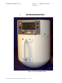
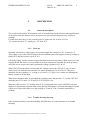
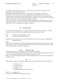
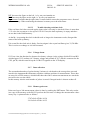
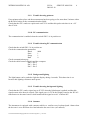
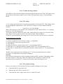
NEUTRON MONITOR
2222A
Service Manual
Wedholm Medical AB, SE-611 29 Nyköping
Phone +46 155 28 03 70, Fax +46 155 26 31 10
e-mail: [email protected] http://www.wedholmmedical.se
WEDHOLM MEDICAL AB
2222 A
SERVICE MANUAL
2009-02-18
Contents
Page
1.
NEUTRONMONITOR 2222A
1
2.1.
2.1.1
2.1.2
2.1.3
2.1.4
2.1.5
2.1.6
2.1.7
2.1.8
2.1.9
2.1.10
2.1.11
2.1.12
2.1.13
2.1.14
2.1.15
2.1.16
2.1.17
2.1.18
2.1.19
2.1.20
2.1.21
2.2.
2.
DESCRIPTION
Function description
Start-up
2
Trouble shooting start-up
Instrument operation
Pulse collection
Menu selection
Voltage alarm
Data collection
Memory print-out
Trouble shooting printout
PC-communication
Trouble-shooting PC-communication
Background lighting
Trouble shooting background lighting
Summer
6
Trouble shooting summer
HV setting 7
HV trouble shooting
Trouble shooting analogue part
Trouble shooting CPU input
External Signal output
Trouble shooting detector
Electronics 9
3.1.
3.2.
3.3.
3.4.
3.5.
3.6.
3.
MAINTENANCE
Amplifier check
Discriminator check
Check of LCD deflection
Software calibration
Trouble shooting software calibration
Neutron calibration
10
10
10
10
11
11
11
4.
13
5.1.
5.2.
5.3.
5.4.
SPECIFICATIONS
5.
FIGURER
Detektorunit 15
Neutronsensitivity
Angeldependence
Neutronsensitivity
J:\Gemensam\Manualer\Digipig\2222-Servicemanual-engelska-1_11.doc akw
2
2
2
3
3
4
5
5
5
6
6
6
6
6
7
7
8
8
8
8
15
16
17
18
WEDHOLM MEDICAL AB
5.5.
5.6.
5.7.
5.8.
5.9.
2222 A
SERVICE MANUAL
2009-02-18
Count loss 19
Block diagram
Typical plateau curve
Adjustment of sensitivity
Presentation board
20
21
22
23
Appendices (normally not included, can be delivered at request)
Presentation Card:
”
”
Display Card:
”
H V Card:
”
Electric diagram digital part
C-321.207 (1)
Electric diagram analogue part C-321.208 (1)
Component location
C-321.214 (1)
Electric diagram
C-321.209 (1)
Component location
C-321.213 (1)
Electric diagram
C-321.210 (1)
Component location
C-422.764 (1)
Upon delivery
BF3 manufacturing certificate
Function test certificate
Neutron calibration certificate
J:\Gemensam\Manualer\Digipig\2222-Servicemanual-engelska-1_11.doc akw
WEDHOLM MEDICAL AB
1..
2222 A
SERVICE MANUAL
2009-02-18
NEUTRONMONITOR 2222A
Figur 1.1 Neutron Monitor 2222 A
J:\Gemensam\Manualer\Digipig\2222-Servicemanual-engelska-1_11.doc akw
1
WEDHOLM MEDICAL AB
2222 A
SERVICE MANUAL
2009-02-18
2.
DESCRIPTION
2.1.
Function description
2
The circuit board marked "Presentation card" is the main board with collection and amplification
of the pulses from the detector and a microprocessor part with presentation of the collected
readings.
Usually when the battery or the external power is connected. M+ will be 4.5 Volt.
-5V is generated by IC17, which gets +5V from IC15.
2.1.1
Start-up
Normally when there is either battery or external supply the voltage over M+ is about 4.5 V.
This voltage is up to the ON/OFF button on the membrane panel and supports back-up voltage to
RAM (IC5) and the real time clock (IC10).
If both the battery and the external support should fail, the back-up battery (BAT) takes over and
supports RAM and clock. It is not possible to start the instrument with only the back-up battery
when D8 acts as stop for the battery against the voltage regulators IC15 & 16.
When ON/OFF on the panel is pressed the M+ voltage reaches the CPU (IC2), pin 34, at the
same time as M+ saturates the transistor T4, which grounds pin 5 at IC15 & 16. This pin is
shutdown for the regulators, i.e. as long as it is above 0.3 V there is no voltage out although the
battery voltage is on the input.
When these shutdown pins are grounded the regulators start and generate +5 V to the CPU and
analogue part (IC15) and +5V to the HV (IC16) if SW2 is set.
When the CPU receives +5V feeding from IC15. It starts and reacts on the ON/OFF push (this
happens so fast that the program starts before the ON/OFF button is released) through pin 34 and
it puts pin 29 high which takes over the feeding of T4 and IC15 & 16 and the instrument is
working.
2.1.2
Trouble shooting start-up
If the instrument fails to start when pushing ON/OFF there are some alternatives for trouble
shooting.
J:\Gemensam\Manualer\Digipig\2222-Servicemanual-engelska-1_11.doc akw
WEDHOLM MEDICAL AB
2222 A
SERVICE MANUAL
2009-02-18
3
a) Nothing happens
Does the voltage over M+ exceed 2.5 V?
This signal must be above 2.5 V to be able to operate the transistor T4. The signal M+ becomes
the signal ON/OFF at pushed button, which then is voltage divided by R27 and R28.
Check the voltage backward towards the batteries if M+ is not over 2.5 V.
According to the leaflet for IC15 the voltage in must be at least +6 V to be able to give +5 V.
Check that there is +6 V on IC15/8.
b) The LCD blinks but drops off when ON/OFF is released
This indicates that there is voltage from the batteries and that IC15 and IC16 gets grounded
shutdown so that they start but that the CPU does not take over.
Check if there is +5 V to the CPU, for example IC2/26.
Check if IC2/29 is set high. This is a must for the instrument to work after ON/OFF has been
released. This port is set high in the beginning of the program and if it is not, this indicates that
the CPU does not reach the program code in IC4. Check that the PROM is correctly mounted.
Check that IC1 sends a reset-pulse to the CPU on about 4.5 V immediately after it has received
VCC.
It is unusual that a CPU fails.
2.1.3
Instrument operation
When the instrument is in operation the CPU communicates with its peripheral circuits, which
are:
IC4 - PROM.
Contains the program code.
IC5 - RAM.
Here the CPU stores the measurement values and measuring data it
has presented and needs in the future.
IC10 - Real time clock. This circuit is totally independent as long as the CPU does not try to
change its settings. It updates time and date and presents these for the CPU when asked for.
At start-up all display segments first are lit up during 5 seconds for the operator to be able to see
that all segments work. After that the version number of the programme is shown. This is also
for the high voltage to stabilise and to avoid disturbance pulses from the loading process.
After this initiation the instrument actively starts to present the neutron flow by collecting pulses
from the detector at IC2/27 and then present them. In ratemeter mode the measurements are
updated every 2 seconds in dose rates above 0.05 mSv/h. Below 0.05 mSv/h there is an update
10 seconds. If the integral mode is chosen the dose is updated every 100 seconds.
2.1.4
Pulse collection
The discharges of at least 5*10-14 Coulomb generated in the detector are transported on the HV
by pin J3 to C16. After C16 only the pulses remain. The pulse is then amplified 11 times through
IC11. By adjust P1 in the feedback of IC12 the amplitude of the pulse can be set. The spectra can
be inspected on IC13/6.
J:\Gemensam\Manualer\Digipig\2222-Servicemanual-engelska-1_11.doc akw
WEDHOLM MEDICAL AB
2222 A
SERVICE MANUAL
2009-02-18
4
T1 and P2 set the discriminator level, i.e. what levels to be removed to avoid noise and
gammapulses. This is inspected on D5.
IC14 and T2 transforms the pulse to a -4V signal and T3 transforms it to TTL level.
From here the TTL pulse goes to J4 for external purposes and further to the CPU, pin 27.
The programme is designed in a way that when there is a pulse on IC2/27 an internal register
counts one step. This is an 8 bit register and when it has reached 255 pulses it is set to zero and
initiates an interrupt, which in turn counts up another register.
After 10 ms there is a new interrupt which adds the total number of pulses during these 10 ms
with the total number of pulses since the start of the measurement. At the same time the two
registers are set to zero and the measurement is restarted.
2.1.5
Menu selection
Pressing INT+PRT will take you to a menu loop that can be used to set the date, to erase the
memory or set an alarm. The menu, which automatically comes up, is 'dAtE'.
INT:
PRT:
Alternates between the three menus.
To select, press the PRT button.
Light button: In the main loop, you can exit the menu at any time and return to monitoring by
using this button.
Note:
If this menu is selected, you should avoid carrying out important integral measurements at the
same time, since the CPU can detect that INT has been activated shortly before you press PRT
and it will terminate the integral measurement.
2.1.5.1
Real time clock
The real time clock IC10 is reached by choosing ’dAtE’ in the menu.
All information relating to the built-in real time clock is saved in the following format: 970114
15:10, i.e. ten minutes past three in the afternoon of January 14, 1997.
When you select this menu, three figures will be displayed which, in normal cases, display the
rate meter value:
00
1
Where the two on the left are date/time and the right is a control figure as shown in Table 2.1.
1 - the year, e.g. 97
2 - the month, e.g. 01
3 - the day, e.g. 14
4 - the hour, e.g. 15
5 - minutes before or after the hour, e.g. 1
Table 2.1
Setting the date
Use the following buttons to change the setting:
J:\Gemensam\Manualer\Digipig\2222-Servicemanual-engelska-1_11.doc akw
WEDHOLM MEDICAL AB
2222 A
SERVICE MANUAL
2009-02-18
5
INT:Increases the figure on the left, i.e. by ten years/months etc.
PRT:Increases the figure on the right, i.e. by one year/month etc.
Light button: Confirms that the right value is entered which causes the program to move forward
to the next entry. When confirming the minutes it returns you to the main menu.
2.1.5.2
Trouble shooting real time clock
If the real time clock does not take up the input value it can only be checked if there is more than
+2 V when the instrument is shut off on IC10/20. If not, the back-up battery is empty and there
are no data in the RAM memory.
As the M+ is operating the clock it should work as long as the instrument works, disregard the
status of the back-up battery.
If it seems like the clock unit is faulty, first investigate it the crystal oscillator gives 32,768 kHz.
This is easier to exchange as it is hole mounted.
2.1.6
Voltage alarm
IC15 has a low-bat function for alarm at low battery voltage via the voltage divider R30 and R31
which triggers IC15 at about 6,0 V battery voltage and grounds IC15/7 which is connected to the
CPU, pin 48, which in turn lits up the LO BATT segment on the LCD display.
2.1.7
Data collection
The accumulated number of pulses during 5 minutes is calculated to the average dose rate and
stored in the instrument RAM memory together with date and time for measurement. These data
are stored in a FIFO memory, which means that when 200 5-minute measurements are stored the
next will write over the oldest.
In this memory also the total number of pulses is stored if integral mode is chosen at shut-off.
2.1.8
Memory print-out
Print-out of up to 200 measurement values is done by pushing the PRT button. This only results
in a copy of the memory to the RS-232 port but does not erase of change the measurement values
in any way. A printout looks as follows:
37.87 uSv/h 970416 10:30
38.12 uSv/h 970416 10:35
J:\Gemensam\Manualer\Digipig\2222-Servicemanual-engelska-1_11.doc akw
WEDHOLM MEDICAL AB
2.1.9
2222 A
SERVICE MANUAL
2009-02-18
6
Trouble shooting printout
If not printout takes place and the measurement has been going on for more than 5 minutes either
the RAM is broken or the communication has failed.
Check that the CPU sends out a pulse train on IC2/21 and that this pulse train then is on ± 9V
after IC6/14.
2.1.10 PC-communication
The communication is enabled when the switch SW1/3 is in position on.
2.1.11 Trouble-shooting PC-communication
Check that the switch SW1/3 is in position on.
Check the communication parameters
Baud:
9600
Start
1
Stopp
1
Data
8
Check communication port
Check the cable between Digipig and the computer.
Pin 2 - Pin 2
Pin 3 - Pin 3
Pin 5 - Pin 5
2.1.12 Background lighting
The light button can be pushed to light the display during 4 seconds. This short time is set
because this lighting consumes much power.
2.1.13 Trouble shooting background lighting
Check that the CPU sends a signal out on IC2/25 when the light button is pushed and that this
signal returns after about 4 seconds. This signal goes via T2 on the Display board to the DC/ACtransformer on the same board. It shall transform the signal to an AC of about 80V.
2.1.14 Summer
The instrument is equipped with a summer which a.o. confirm every keyboard push. Alarm when
the dos rate is over the alarm level and when the dos rate is low (see manual).
J:\Gemensam\Manualer\Digipig\2222-Servicemanual-engelska-1_11.doc akw
WEDHOLM MEDICAL AB
2222 A
SERVICE MANUAL
2009-02-18
7
2.1.15 Trouble shooting summer
The summer is placed on the display board and its signal comes from IC2/24. This signal varies
during the time period the summer is to be heard. This signal also passes T2 on the display
board.
2.1.16 HV setting
A +5V voltage generated from IC16 on the presentation board runs the HV. That voltage can be
varied through the components P3, SW3, R36-R39. Voltage out can be adjusted with the
formula:
Vout(IC16)=1.22*(R1+R2)/R1
Where R2 in this case is R36 and R1 is the components P3, R37 and R38-R39, i.e. everything
between IC16/VSET and ground.
This leads to that SW3 affects the value of R1, which affects the voltage over J6 in three firm
steps. These levels are there to set HV fast between 2400, 2500 and 2600 V.
As the HV is proportional to the voltage on J6 it can be set before the HV board is connected.
Rough adjustment of the HV:
1) Connect a voltmeter between J6 pin 1 and 6 (+ and ground).
2) Turn both SW3 connectors in position OFF.
3) Turn SW2 on.
4) Adjust P3 until the voltmeter shows 4.35 V (corresponding 2400V).
5) Turn SW3 # on 1 and check that the voltmeter shows 4.5 V (corresponding 2500 V).
6) Turn SW3 #1 off and SW3 #2 on and check that the voltmeter shows 4.7 V (corresponding
2600 V).
The HV can be measured on the soldering pin ”J7” on the presentation board (see figure
5.9).(Note! Use high ohm or electrostatic voltmeter.)
Warning
HV is on both soldering pins on the presentation board and HV capacitors. Depending on that
the load resistance is very large, about 100 Gohm, the HV remains for a while after the
instrument has been turned off . Caution must be taken when removing the cover.
2.1.17 HV trouble shooting
If there is not about 2.5 kV from the HV board a number of things can be wrong.
1)
Check that SW2 is in position ON
2)
Measure that IC16 delivers about 4.5 V.
3)
Check that the same voltage comes in to J1 on the HV board.
J:\Gemensam\Manualer\Digipig\2222-Servicemanual-engelska-1_11.doc akw
WEDHOLM MEDICAL AB
2222 A
SERVICE MANUAL
2009-02-18
8
Note
If both poles on SW3 are in position ON the high voltage will be much higher than normally.
Switching of the SW3 #1 or #2 with power on can generate too high voltage and damage the
detector or other components.
2.1.18 Trouble shooting analogue part
If at application of electric pulses on C16 there are no pulses on the LCD probably one of the
OP-amplifiers IC 11-14 or the pulse input PA7 on IC2 is damaged.
2.1.18.1
Trouble shooting OP-amplifier
IC14 can be examined by applying TTL pulses in the joint IC13, R17, C23 and C24, this time
with ground connection between the pulse generator and the instrument.
IC13 can be examined by applying 0.1 V p-p pulses with ground connection in the joint C21 and
R14 and examine the pulse train at IC13/6.
IC12 and IC11 can not be tested electrically as the signals from the detector part still are so low.
2.1.19 Trouble shooting CPU input
Apply for example 3600 cps TTL pulses on PA7/IC2 from a pulse generator. Because of T3's
transistor output PA7/IC must be tested without ground connection, i.e. only pulses on the input.
If the instrument presents mSv/h the input is working. Note that as no ground is connected the
number of pulses will not correspond to mSv/h related to 1 pulse = 1.39 µSv/h. If this relation
shall be tested in this way the collector of T3 and R25 must be soldered away and ground
connector be used.
2.1.20 External Signal output
The pulses sent out to the CPU can be checked through the external "SIGNAL OUT".
The difference between these pulses and what is presented on the LCD is the conversion factor
of 1.39 and the software calibration factor.
The Signal out is controlled by the software. Normally the Signal out is disabled too increase the
lifetime of the battery. To enable/disable the "Signal Out" choose "Por" in the setup menu
2.1.21 Trouble shooting detector
If the electric calibration is performed and working but there are no pulses at neutron calibration
something is wrong with the detector unit. Check that there is HV to the detector. If there is HV
J:\Gemensam\Manualer\Digipig\2222-Servicemanual-engelska-1_11.doc akw
WEDHOLM MEDICAL AB
2222 A
SERVICE MANUAL
2009-02-18
9
it is easiest to exchange the detector, as there is not possibility to test the detector in any other
way.
2.2.
Electronics
A block diagram on the instrument is shown in Figure 5.6. Drawings for the presentation board
are C-321.207, C-321.208 and C-321.214 and for the display board C-321.209 and C-321.213.
The pulses from the detector are amplified in the pulse amplifier and the discriminator level is
set on a level which discriminates the noise and gamma pulses meaning a standard pulse out for
each incoming neutron pulse. The standard pulse is mated to a micro controller type Motorola
68HC11 that calculates and presents the pulses in mSv/h and as an option also the dose in µSv or
mSv. The standard pulses are available on the ratemeter board and on the BNC connector
PULSE OUT, which are taken out through connector J4 on the presentation board.
The HV source consists of a constant voltage source, a DC-AC transformer, a HV transformer
and a cascade rectifier, see drawing C-321.210 and C-422.764. With the switch SW3 the HV can
be changed in three steps, 2400, 2500 and 2600 V, to verify that the HV plateau is correct, see
Figure 5.7. The same function is used for compensation of HV deflection at extremely low
temperatures.
The HV can be switched off with SW2 without influencing the rest of the electronics.
J:\Gemensam\Manualer\Digipig\2222-Servicemanual-engelska-1_11.doc akw
WEDHOLM MEDICAL AB
2222 A
SERVICE MANUAL
2009-02-18
3.
MAINTENANCE
3.1.
Amplifier check
10
Turn the 5K-potentiometer (P1) to the center position. Test pulses with negative polarity shall be
fixed to pin J3 on the presentation board through a connection board according to Figure 5.8.
The charge applied through the capacitor is U*1*10-12 Coulombs, where U is the test pulse
amplitude in volts.
The output pulse from the op-amplifier IC13 pin 6 (see figure 5.8 testpoint amplifier) and
drawing on "Adjustments on the presentation board” are shown in Figure 5.8 for two different
input charges.
The amplifier is very sensitive and to get the correct reading it is necessary to protect the
amplifier from external electromagnetic fields.
3.2.
Discriminator check
The discriminator level can be set by P2 (drawing C-321.208). The nominal value is from -0.5V
to -2V, measured on R18, D5, R19 and R20 common point.
This level regulation is done to avoid that gamma pulses and noise are counted. The final
discrimination adjustment is done at the neutron calibration.
The pulse out is checked from the front panel of the instrument. Normally the output amplitude
is about + 5V if the input pulse is 10-12 Coulombs. Then input pulse of 10-13 Coulombs will
normally not give any pulse at the external output.
3.3.
Check of LCD deflection
Feed negative pulses into the amplifier as described in Chapter 3.1 "Check of LCD deflection"
and set the discriminator level to -1V. Let the pulse frequency be 4 pulses per second (pps). The
dose rate shall then be approximately 0.010 mSv/h. (It depends on the calibration of the
monitor).
Let the pulse frequency be 720.000 pps check that OVERFLOW is lit on the LCD. Check the
instrument deflection for the following dose rate 1, 10, 102, 103, 104 and 105 µSv/h.
J:\Gemensam\Manualer\Digipig\2222-Servicemanual-engelska-1_11.doc akw
WEDHOLM MEDICAL AB
3.4.
2222 A
SERVICE MANUAL
2009-02-18
11
Software calibration
When the instrument has been calibrated with known pulses and a measurement with a known
neutron source shows a certain deviation a software factor can be added. The software factor is
initiated to 1.00.
This calibration factor is burnt into the internal EEPROM of the microcomputer and is reached
by activating switch 1 at SW1 on the presentation board. The calibration value (01.00) and the
current integrated dose (514.9 µSv) are shown on the LCD:
01.00
514.9
µSv
Always wait with calibration until the first dose value after 100 seconds. Increase the calibration
factor with INT and decrease with PRT. The dose will be updated all the time with the new
calibration factor.
Finish by deactivating SW1/1 and switching the monitor off/on. The new calibration value will
be burnt into the EEPROM.
Note 1:
If this factor deviates from 1.00, the value on the display will deviate from the value which can
be calculated by counting the number of pulses on the BNC-connector ”SIGNAL OUT” as these
pulses are taken out before the microcomputer.
Note 2:
If the light button is pushed when SW1/1 is activated, the background light is not switched off as
both these functions are handled by interrupts. If the light button has been pushed SW1/1 must
be deactivated and the instrument switched off.
3.5.
Trouble shooting software calibration
If the instrument does not seem to update the dose value with a new calibration factor probably
the EEPROM of the microprocessor has been destroyed or been burnt too many times. Restart
the instrument and try to change the calibration factor. If it not work change the CPU.
3.6.
Neutron calibration
The following equipment is needed:
−
−
−
−
neutron source (for example 100 GBq Am-Be)
oscilloscope (30 MHz)
pulse counter, minimum 10kOhm put
gamma source (for example 2000 GBq Cs-137)
It is supposed that a thorough electric calibration has been performed before this calibration is
done.
Procedure
J:\Gemensam\Manualer\Digipig\2222-Servicemanual-engelska-1_11.doc akw
WEDHOLM MEDICAL AB
2222 A
SERVICE MANUAL
2009-02-18
12
1. Perform 3 measurements from different distances. Check the dose rate on the LCD and/or
external pulse output. Fine adjusts the amplification with P1 if necessary.
2. Put the instrument beside a gamma source (Cs-137) so you get the dose rate 2 Gy/h. Adjust
the discriminator pot R16 on the ratemeter board so that the deflection is less than 5 µSv/h to
secure gamma insensitivity.
Note
If the neutron dose rate sensitivity is checked against a known neutron source, one has to
remember that the contribution from scattered neutron radiation must be attended to, if not
special arrangements have been taken to avoid this, in other case it can cause at least a 25%
misreading above the theoretical dose value.
J:\Gemensam\Manualer\Digipig\2222-Servicemanual-engelska-1_11.doc akw
WEDHOLM MEDICAL AB
4.
2222 A
SERVICE MANUAL
2009-02-18
13
SPECIFICATIONS
Microprocessor:
Software:
Real time clock:
Display:
Display of dose rate:
Analogue display:
Digital display:
Storage of values:
Printing:
Statistical error:
Motorola 68HC11
C-code stored in external EPROM
Can be set by the user. Displays the date
and time in the following format: 970417
14:41. The backup battery ensures that the
clock continues to work even during battery
replacement.
Graphic LCD with optional background
lighting at 4-second intervals.
Logarithmic scale in the range of
0.001 - 100 mSv/h.
If the value exceeds 100 mSv/h, the
instrument will display 100 mSv/h.
In the range of 0.001 - 999.9 mSv/h, above
999.9 mSv/h, 999.9 and OVERFLOW will
blink with a frequency of 1 Hz.
Every 5 minutes the dose rate value is
stored in an external RAM with a spill over
function. The entire memory can be erased.
The backup battery ensures that the
measurement value is stored even during
battery replacement.
Via RS-232 to terminal program.
Printout from the memory of the measuring
values with time indication. LO BATT,
ALARM and OVERFLOW indication are
printed out with time indication.
Maximum 20%. At entrance in a weak
neutron field the error can be higher during
a short period and the instrument will give
an audible alarm.
0.025 eV - 17 MeV
0.35 – 0,50 cps/µSv/h (individual variation)
2 Gy/h gives < 5 µSv/h
Energy range:
Neutron sensitivity:
Gamma sensitivity:
Minimum pulse charging
from detector:
5 * 10-14 Coulomb
(HV = 2500 V)
Charge amplification Amplification:
2V/10-13 Coulomb
Differentiation time:
1 µs
J:\Gemensam\Manualer\Digipig\2222-Servicemanual-engelska-1_11.doc akw
WEDHOLM MEDICAL AB
Discriminator range:
External pulse port
Amplitude:
Duration:
Load:
HV supply Voltage:
Operation:
Power supply:
Internal:
Operating time:
Battery testing:
External (option):
Temperature range:
Dimensions Diameter:
Length:
Weight:
1
2
2222 A
SERVICE MANUAL
2009-02-18
About -0.5V ... -3V 1
about +2.8V
500 ns
10 kohm min
+2200V - 2700V 2
1 V/°C
Alkaline batteries 6 x 1.5V
IEC LR14
80 h
Tested electronically. 'LO BATT' lights up
at the LCD when there is about an hour left
of battery capacity.
Through the 'External Power' connector, an
eliminator, which will take over the battery
function can be connected. This eliminator
can be connected and disconnected while
the instrument is operating.
-10°C - +40°C
215 mm
325 mm
10.5 kg, including batteries
The exact value depends on the neutron calibration.
The exact value depends on the individual BF3-tube. HV is normally 2400V at "plateau knee".
J:\Gemensam\Manualer\Digipig\2222-Servicemanual-engelska-1_11.doc akw
14
WEDHOLM MEDICAL AB
2222 A
SERVICE MANUAL
2009-02-18
5.
FIGURES
5.1.
Detector unit
Figure 5.1
NEUTRON MONITOR 2222 A
Detector unit
J:\Gemensam\Manualer\Digipig\2222-Servicemanual-engelska-1_11.doc akw
15
WEDHOLM MEDICAL AB
2222 A
SERVICE MANUAL
2009-02-18
5.2.
Neutronsensitivity
o
x
•
Broad beam θ = 90° (se figure 5.3)
Broad beam θ = 0° (se figure 5.3)
Isotropic neutrons
Figure 5.2
NEUTRON MONITOR 2222 A
Neutron sensitivity as a function of energy
J:\Gemensam\Manualer\Digipig\2222-Servicemanual-engelska-1_11.doc akw
16
WEDHOLM MEDICAL AB
2222 A
SERVICE MANUAL
2009-02-18
5.3.
Angular dependence
180
195
210
1,4
165
150
1,2
225
135
1
0,8
240
120
0,6
0,4
255
105
0,2
270
90
0
285
75
300
60
315
45
330
30
345
15
-30°
0°
+30°
0
Figure 5.3 NEUTRON MONITOR 2222 A
Angle dependence in relation to count speed
J:\Gemensam\Manualer\Digipig\2222-Servicemanual-engelska-1_11.doc akw
17
WEDHOLM MEDICAL AB
2222 A
SERVICE MANUAL
2009-02-18
5.4.
Neutronsensitivity
Figure 5.4 Difference from ideal response
J:\Gemensam\Manualer\Digipig\2222-Servicemanual-engelska-1_11.doc akw
18
WEDHOLM MEDICAL AB
2222 A
SERVICE MANUAL
2009-02-18
5.5.
Count loss
Figure 5.5
NEUTRON MONITOR 2222 A
Count loss at varying pulse repetition frequencies
J:\Gemensam\Manualer\Digipig\2222-Servicemanual-engelska-1_11.doc akw
19
WEDHOLM MEDICAL AB
2222 A
SERVICE MANUAL
2009-02-18
5.6.
Block diagram
B a tte ry e lim in a to r
( o p tio n )
E x te rn a l
Pow er
6 * 1 .5 V B a tte r ie s
H ig h v o lta g e b o a r d
2600 V
D C to D C
c o n v e r te r
B F 3 tu b e
A m p lif ie r
D e te c to r
D is c r im in a to r
CPU,
M e m o ry
RS232
P r e s e n t a t io n b o a r d
D is p la y b o a rd
S ig n a l O u t
M e m b ra n e p a n e l
Figure 5.6
NEUTRON MONITOR 2222 A
Block diagram
J:\Gemensam\Manualer\Digipig\2222-Servicemanual-engelska-1_11.doc akw
20
WEDHOLM MEDICAL AB
5.7.
2222 A
SERVICE MANUAL
2009-02-18
Typical plateau curve
1000
900
800
700
cps
600
500
400
300
200
100
0
2000 2100 2200 2300 2400 2500 2600 2700 2800 2900 3000 3100
High Voltage
Figure 5.7 NEUTRON MONITOR 2222 A
Typical plateau curve for the BF3-tube
J:\Gemensam\Manualer\Digipig\2222-Servicemanual-engelska-1_11.doc akw
21
WEDHOLM MEDICAL AB
5.8.
2222 A
SERVICE MANUAL
2009-02-18
Adjustment of sensitivity
J3 på
presentationskortet
1pF
U
100Ω
Figure 5.8 Amplifier check
J:\Gemensam\Manualer\Digipig\2222-Servicemanual-engelska-1_11.doc akw
22
WEDHOLM MEDICAL AB
2222 A
SERVICE MANUAL
2009-02-18
5.9.
23
Presentation board
HV on/off
HV testpoint
HV switch
Amplifier
adjustment
C-11.272
000202
C16
C32
Testpoint
amplifier
R10
Testpoint
discriminator
HV adjustment
Discriminator
adjustment
Figures 5.7
NEUTRON MONITOR 2222 A
J:\Gemensam\Manualer\Digipig\2222-Servicemanual-engelska-1_11.doc akw