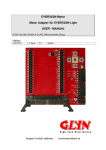
1
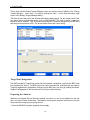
USER’S MANUAL ZC702 BSP Board Support Package BLUNK Microsystems =&2 BSP Board Support Package User’s Manual SOFTWARE LICENSE AGREEMENT Blunk Microsystems’ embedded software products include full source code. Licensees are generally only allowed to release derived code in a fully linked executable format and such distributions are usually royalty-free. Redistribution of source code or derived object code is usually specifically prohibited. Consult your license agreement with Blunk Microsystems for specifics on these and other points. Violation of the license agreement can result in its termination. DISCLAIMER Although Blunk Microsystems strives to develop high quality software and accurate documentation, this manual and software are provided “AS IS” and without warranty of any kind. Blunk Microsystems specifically disclaims any responsibilities for any damages, special or consequential, connected with the use of this software. TRADEMARKS CrossStep, TargetOS, TargetFAT, TargetTCP, TargetTools, TargetXFS, and the Blunk logo are trademarks of Blunk Microsystems. COPYRIGHT NOTICE Copyright © 2014 Blunk Microsystems. All rights reserved. Revision Number: 20141 Blunk Microsystems Tel: 408/323-1758 www.blunkmicro.com [email protected] Web: www.blunkmicro.com [email protected] Revision History Revision 20141 20140 Reason Some corrections and more info on Abatron ‘config’ command. First revision. Date Sep 12 2014 May 23 2014 Intentionally left blank. Contents 1 Using The BSP Overview ........................................................................................................... 1-1 ZC702 Configuration ......................................................................................... 1-1 USB-to-UART Bridge ........................................................................................ 1-1 Abatron Configuration File................................................................................. 1-2 BOOT.BIN ......................................................................................................... 1-2 Resetting the Target .......................................................................................... 1-2 TargetTools Debug Target ................................................................................ 1-3 TargetTools Integration ..................................................................................... 1-4 Preparing the Abatron ....................................................................................... 1-4 Technical Support ............................................................................................. 1-5 Intentionally left blank. Using The BSP 1 Overview Xilinx Zynq SoC JTAG debugging is done by running a First Stage Boot Loader (FSBL) that initializes the Zynq Processing System before taking JTAG debug control. For the ZC702 BSP, this is done by configuring the boot mode jumpers for SD card boot, having the FSBL on an SD card (as “BOOT.BIN”), and using a STARTUP command in the Abatron config file with enough delay to let FSBL initialization finish before stopping CPU 0 in debug mode. The following sections explain this configuration in more detail. ZC702 Configuration 1. Configure the following switches (1=up and 0=down when viewing the labels) on the ZC702: Switch SW16.1: Setting 0 Effect Cascaded JTAG SW16.2-5: 0110 SD boot mode SW10: 11 J58 connector selected 2. Connect the standard 20-pin ARM JTAG cable to J58. Pin 1 of the cable (marked by a red wire) connects to pin of the socket (labeled ‘1’ on the board silk screen). NOTE: It is critical that the JTAG cable is never inserted or removed while power is applied to the board. Always power-down the target board before inserting or removing the JTAG connection. Failure to heed this may destroy your board! 3. Insert an SD card that contains a BOOT.BIN image. 4. Connect the power supply to J60 and power on the ZC702 board. 5. Connect a USB cable from J17 to your PC and open a serial terminal with the baud rate set to 115200. More information about this virtual UART connection is below. USB-to-UART Bridge The ZC702 board contains a USB-to-UART bridge. Zynq UART channel 1 is wired to a Silicon Labs CP2103GM USB-to-UART bridge device. Silicon Labs provides Virtual COM Port (VCP) drivers that make the USB-to-UART bridge appear as a PC COM port. The VCP device drivers must be installed on the host PC prior to establishing communications with the ZC702 board. If the CP2103GM driver is not automatically recognized, it can be downloaded from Silicon Labs Website: https://www.silabs.com/Pages/default.aspx. Find the appropriate drivers by searching for "VCP drivers CP210x". The USB connection is J17. The baud rate is fixed as 115200. 1-1 1 Using The BSP Abatron Configuration File In order to communicate with the Zynq processors, the Abatron BDI3000 needs to load a configuration file. The file “abatron.cfg” is provided for this purpose in the BSP. Before using the BDI3000 for the first time after a power cycle, you must have a TFTP server ready to serve this file. The TFTP server address is set by telneting into the BDI3000. Entering ‘config’ with no parameters displays the current settings related to loading the configuration file: zc702#0>config BDI Firmware: BDI CPLD ID : BDI CPLD UES: BDI MAC : BDI IP : BDI Subnet : BDI Gateway : Config IP : Config File : 1.19 01285043 bd080064 00-0c-01-33-49-02 192.168.1.49 255.255.255.0 255.255.255.255 192.168.1.51 abatron.cfg For example, to configure the BDI3000 to load “abatron.cfg” from a TFTP server at IP address 192.168.1.51, enter “config abatron.cfg 192.168.1.51”. This both saves the host IP address and loads the configuration file. The ‘config’ command also allows you to change the BDI3000’s IP address. The full syntax for ‘config’ and other commands is provided in response to “help”. The telnet connection is closed each time the configuration file is downloaded. You will need to re-open it and keep an open telnet window during debugging. Before the ZC702 ‘abatron.cfg’ file is loaded, the BDI3000 Telnet prompt is “Core#0>”. Afterward, the prompt changes to “zc702#0>”, showing that you are talking to Zynq CPU0. BOOT.BIN The Zynq internal bootrom is the first code to run after a reset. Its job is to load and start an external FSBL. The ZC702 FSBL is a combination of Xilinx code and proprietary code from Blunk Microsystems. You can build it by repeating the following steps: 1. Load and build "bsps\arm\zc702\fsbl_app\fsbl_app.gbp". 2. Copy "bsps\arm\zc702\fsbl_app\output\fsbl_bsp\app.elf" to "bsps\arm\zc702\boot_gen". 3. Run createBoot.bat in the boot_gen directory (may need to run Xilinx's settings32.bat first, to set Path variable. 4. Copy the resultant BOOT.BIN file to an original Standard-Capacity SD card. SDHC cards will fail. The boot_gen “bootimage.big” file may be modified to include an FPGA bitstream in BOOT.BIN that is automatically loaded by the FSBL. Resetting the Target With the above configuration finished, you can reset the ZC702 Processing System (CPUs and peripherals) by entering “reset” in the BDI3000 Telnet shell. The following output should result: c702#0>reset 1-2 Using The BSP 1 - TARGET: - TARGET: - TARGET: - TARGET: - Core#0: - Core#0: - Core#0: - Core#0: - Core#1: - Core#1: - Core#1: - Core#1: - TARGET: - TARGET: - TARGET: - TARGET: zc702#0> processing reset request BDI executes scan chain init string Bypass check 0x00000001 => 0x00000002 JTAG exists check passed ID code is 0x4BA00477 DP-CSW is 0xF0000000 DBG-AP at 0x80090000 DIDR is 0x35137030 ID code is 0x4BA00477 DP-CSW is 0xF0000000 DBG-AP at 0x80092000 DIDR is 0x35137030 Reset sequence passed resetting target passed processing target startup .... processing target startup passed There will be a significant delay between the “processing target startup ....” and “processing target startup passed” messages. The length of the delay is set – in milliseconds - by the parameter that follows “STOP” in the Abatron config file’s STARTUP command. When STARTUP is used, then after completing all other config file initialization the BDI3000 lets the target run. The startup delay is the time between letting the target processors run and then halting them again in debug mode. It must be long enough to let the FSBL complete its board initialization. An example STARTUP command is: #0 STARTUP STOP 7000 ;let boot code run 7 sec After the FSBL has completed its initialization, it prints the following to the UART connection: Blunk Microsystems dummy FSBL for JTAG debugging You should see this every time you enter “reset” on the BDI3000 Telnet shell. If it doesn’t appear, then FSBL initialization may not have completed and debugging will be erratic because the target system is only partially initialized. If the FSBL changes, to perform longer initialization, you may need to change the STARTUP command also, to ensure it waits for the target system to be fully initialized. You will also see the UART message each time the debugger is closed normally, because when it is closed normally, the debugger sends a reset command to the BDI3000. If a debug session ends abnormally – such as by a bus error – the reset command may not be sent. If you observe that a previous debug session did not end with the above UART message, then you should reset the target manually by giving the Telnet “reset” command. A hardware reset can be made by depressing pushbutton SW2. This forces PS_SRST_B_SW to strobe low, resulting in a system reset. TargetTools Debug Target At this point, you are almost ready to launch the CrossStep debugger on the ZC702, but one more step is needed. Before you are able to debug with TargetTools, you must configure a Debug Target matching the board and connection type you will use. 1-3 1 Using The BSP This is done with the Debug Targets Manager, which you access from the gBuild ToolsDebug Targets Manager… menu entry. You start by clicking the “New...” button near the bottom right corner of the Debug Targets Manager dialog. The fields in the lower part of the window describe the debug target. For the “target name” field, you should select a meaningful name, such as “BDI3000CA9”. The “type of target” combo box should be set to “Abatron”. The IP Address should be the IP address assigned to your BDI3000 and the port should remain 2001. The picture below shows the correct setup. TargetTools Integration The BSP includes a TargetTools project file that compiles, assembles, and links the BSP code into the library file "bsp.a". The BSP project file, linker command file, and library file are used by TargetOS applications. Applications configure which BSP they are using by setting the BoardSupport Package path in the General tab of the Project Options dialog. Preparing the Abatron Abatrons are shipped with no firmware installed, so before you use a new Abatron for the first time, you have to install its firmware. The Abatron manual gives complete instructions, but these short instructions might get you going quicker: - Power the BDI3000 using the supplied power supply. 1-4 Using The BSP 1 - Use the supplied serial cable to connect the BDI3000 to a serial port on your PC. - Run Abatron's firmware updater program 'b30a11gd.exe'. - Select the correct COM Port and click 'Connect'. (If the correct port is unknown, you can try connecting to every port present and checking for success, but first find the list of ports via a program like HyperTerminal. The Abatron b30a11gd.exe lists ports that don't exist.) - Once connected, install the firmware by clicking 'Update'. - Set the configuration by supplying the Abatron's IP address and mask, and the IP address of your PC. If there is no gateway between the Abatron and your PC, leave the default gateway as the broadcast address. Click 'Transmit'. - Close the Setup program by clicking 'Ok'. - With target power off, connect the JTAG cable between the target and your BDI3000. - Connect an Ethernet cable to your BDI3000. - Power the target. Always power the target last and turn it off first. Of course, you might actually leave it on for days and days. Technical Support For technical support, contact Blunk Microsystems via email at [email protected], phone at 408/323-1758, or fax at 408/323-1757. 1-5 1 Using The BSP Intentionally left blank. 1-6 Blunk Microsystems LLC Tel: (408) 323‐1758 Fax: (408) 323‐1757 E‐mail: [email protected] Web: www.blunkmicro.com