1
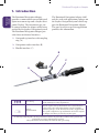
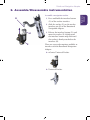
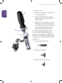
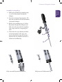
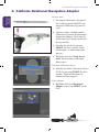
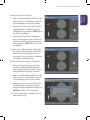
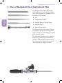
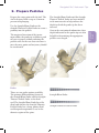
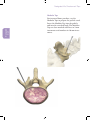
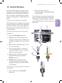
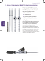
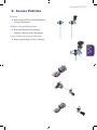
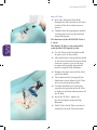
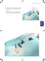
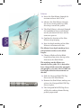
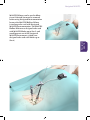
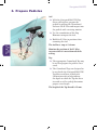
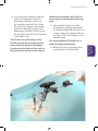
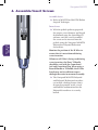
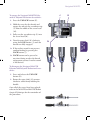
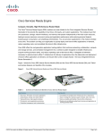
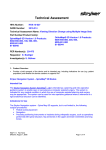
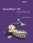
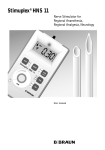
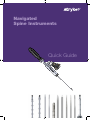
Navigated Spine Instruments Quick Guide Rotational Navigation Adapter Rotational Adapter 1. Introduction The Rotational Navigation Adapter provides a connection between dedicated Spine instrument tips and a Stryker Navigation Tracker. The instrument tips can be rotated within the adapter while being tracked by the Stryker Navigation System. The Rotational Navigation Adapter provides three mechanical interfaces. The Rotational Navigation Adapter shall only be used with application packages on the Stryker Navigation System which support the Rotational Navigation Adapter. The part list of the respective application provides this information. 1. Navigated tip interface with coupling ring (A) 2. Navigation tracker interface (B) 3. Handle interface (C) B C A i User Group Medical Professional (Surgeons, scrub nurses and employees in the clinical processing department.) Refer to documentation For the required safety information and contraindications, please refer to the safety informations, supplied with the software packages, to the instructions for use, supplied with the system components, tips and handles and to the surgical techniques brochures provided by Stryker Spine. As with any technical guide, the surgeon should consider the particular condition of the patient and perform the necessary adjustments if required. Safety and caution should always be utilized before proceeding. Rotational Navigation Adapter Assemble a navigation tracker B 1. Press and hold the interface button (D) of the tracker interface. 2. Slide the tracker (E) on the tracker interface pin (B) of the Rotational Navigation Adapter. D E 3. Release the interface button (D) and move the tracker (E) slightly until the interface button snaps back and the tracker is firmly attached to the interface (B). There are two tracker options available to interface with the Rotational Navigation Adapter: ff nGenius Universal Tracker ff Universal Tracker Rotational Adapter 2. Assemble/Disassemble instrumentation Rotational Navigation Adapter Rotational Adapter Assemble a handle F 1. Pull back and hold the coupling ring (G) of the handle (F). 2. Slide the handle over the handle interface (C) of the Rotational Navigation Adapter. 3. Release the coupling ring (G) of the handle (F) and turn the handle until the coupling ring snaps back into its original position and the handle is firmly attached to the interface. G C There are three handle options with the Rotational Navigation Adapter. All handles are cannulated and ratcheting and can be used interchangeably with the Navigated Xia 3 and Navigated MANTIS instruments. ff Navigated Round Handle ff Navigated T-Handle ff Navigated T-Handle (Short) Rotational Navigation Adapter Rotational Adapter Assemble a navigated tip 1. Pull back and hold the coupling ring (A) of the Rotational Navigation Adapter. 2. Insert the navigated tip interface (H) into the tip interface of the Rotational Navigation Adapter. 3. Release the coupling ring (A) of the Rotational Navigation Adapter and fully insert the tip until the coupling ring snaps back to its original position. 4. Check that the tip is firmly attached to the tip interface. The tip is correctly seated if the slope of the tip is aligned with the adapter interface as shown in the following: A H Fully inserted Polyaxial Screwdriver Fully inserted Calibration Tip Rotational Navigation Adapter Rotational Adapter 3. Calibrate Rotational Navigation Adapter Prepare tools 1. For adapter calibration (Navigated Xia 3 and Navigated MANTIS) the navigated Calibration Tip must be used. 2. Attach a tracker, a handle and the Calibration Tip onto the Rotational Navigation Adapter. Check that the Calibration Tip is firmly attached to the tip interface. 3. Initialize the tracker by pressing SELECT for three seconds. Upon initialization, an information box appears. 4. Highlight and select Track Instrument. An instrument calibration dialog starts. Initialize calibration device ff Initialize the Point Calibration Device (PCD) by pressing SELECT for three seconds. Upon initialization, an information box appears. Select adapter ff Highlight and select Rotational Adapter by pressing SELECT on the PCD. Calibrate Rotational Adapter 1. Make sure that both the PCD and the tool tracker are visible and centered in the working space of the camera. 2. Touch the center of any of the PCD’s validation discs with the tip of the Calibration Tip and press SELECT on the PCD to confirm. 3. Touch the center of the validation disc on the opposite side of the PCD with the tip of the calibration instrument and press SELECT on the PCD to confirm. ff After the calibration, the Calibration Tip can be removed and replaced by one of the navigated Spine instrument tips. The tips must be validated according to the next step. Validate Rotational Adapter calibration 1. Insert the required tip into the tip interface of the Rotational Navigation Adapter and check that the tip is firmly attached to the tip interface. 2. Make sure that both the PCD and the tool tracker are visible and centered in the working space of the camera. 3. Touch the center of any of the PCD’s validation discs with the tip of the navigated Spine Instrument and press SELECT on the PCD to confirm. ff If you change tools, validate the new tool before usage. Rotational Adapter Rotational Navigation Adapter Navigated Xia 3 Instrument Tips 1. Use of Navigated Xia 3 Instrument Tips The Navigated Xia 3 Instrument Tips are designed to be used with the Stryker Xia 3 Spinal System. The Navigated Xia 3 Instrument Tips include: Navigated Xia 3 ff Awl ff Straight Blunt Probe ff Straight Thoracic Pedicle Probe ff Modular Taps ff Polyaxial Screwdriver The Navigated Xia 3 Instrument Tips are assembled to the Rotational Navigation Adapter using the methodology described in the chapters before. The Polyaxial Screwdriver has a marking on the long, round shaped sides of the interface. This marking indicates the correct seating of the Polyaxial Screwdriver when it meets the adapter interface. Navigated Xia 3 Instrument Tips 2. Prepare Pedicles Use the Straight Blunt Probe or the Straight Thoracic Pedicle Probe to create a pathway into the pedicle. The navigated insertion of the instrument allows the probe tip to follow a path of least resistance without violating the pedicle walls. In the case that resistance is met, the entry point and trajectory should be reevaluated. The Straight Blunt Probe and the Straight Thoracic Pedicle Probe are laser marked in 10 mm intervals to help indicate the depth in which the probe tip has been inserted. Next to the navigational infomation, these depth indicators on the probe tips are also helpful in determining the appropriate pedicle screw length. Probes There are two probe options available. The primary differentiating feature of the Straight Blunt Probe and the Straight Thoracic Pedicle Probe is the distal end. The Straight Blunt Probe has a flat distal end whereas the Straight Thoracic Pedicle Probe has a sharp, pointy distal end designed to optimize its use in the thoracic region of the spine. Straight Blunt Probe Straight Thoracic Pedicle Probe Navigated Xia 3 Prepare the entry point with the Awl. The Awl is designed with a stop at 13 mm to prevent overplunging. Navigated Xia 3 Instrument Tips Navigated Xia 3 Modular Taps For increased bone purchase, use the Modular Taps to prepare the pedicle canal. Insert the Modular Tap into the pedicle and into the vertebral body. The Modular Taps are laser marked with lines in 5 mm increments and numbers in 10 mm increments. Navigated Xia 3 Instrument Tips 3. Insert Screws Navigated Xia 3 Polyaxial Screwdriver The Navigated Xia 3 Polyaxial Screwdriver includes a locking feature that is designed to provide tactile, visual, and audible confirmation that the Polyaxial Screwdriver is securely locked. 2. Rotate the outer shaft (N) counterclockwise while firmly holding the handle. Once all of the screws have been placed; refer to the Xia 3 Spinal System Surgical Technique for rod contouring, rod linkage, final tightening, and cross connector placement. J To engage the Navigated Xia 3 Polyaxial Screwdriver: 1. Press the UNLOCK button (K). 2. Hold the screw by the threads and engage the tabs on the screwdriver tip (L) into the saddle of the screw head (M). 3. Fully seat the screwdriver tip (L) into the screw head (M). 4. Turn the outer shaft (N) clockwise using the LOCK button (J) until the threads are fully engaged. ff If the ratchet sound is not present, confirm locking by pressing the LOCK button (J). ff LOCK button can be pressed at any time during or after the thread engagement action, if ratchet sound is not desired. To disengage the Navigated Xia 3 Polyaxial Screwdriver: 1. Press and release the UNLOCK button (K). L M N K Navigated Xia 3 With the pedicle pathway prepared, and the proper screw diameter and length detemined using the SpineMap 3D software, the screw can be inserted into the pedicle using the Navigated Xia 3 Polyaxial Screwdriver. Navigated MANTIS 1. Use of Navigated MANTIS Instrumentation The Navigated MANTIS Instruments are designed to be used with the Stryker MANTIS Spinal System. The Navigated MANTIS Instruments include: ff Cannulated Awl ff Cannulated Taps ff MANTIS Polyaxial Screwdriver ff Reduction Polyaxial Screwdriver Navigated MANTIS ff Tap Sleeve The Navigated MANTIS Instrument Tips are assembled to the Rotational Navigation Adapter using the methodology described in the chapters before. The MANTIS and MANTIS Reduction Polyaxial Screwdrivers have a marking on the long, round shaped sides of the interface. This marking indicates the correct seating of the Polyaxial Screwdrivers when they meet the adapter interface. Navigated MANTIS 2. Access Pedicles Incision ff Refer to MANTIS or MANTIS Redux Surgical Technique. Calibrate Navigated Instrument ff Refer to Rotational Navigation Adapter Chapter in this document. Vector Calibrate Navigated Jam Shidi Navigated MANTIS ff Refer to SpineMap 3D User Manual. Navigated MANTIS Insert K-Wire ff Insert the Navigated Jam Shidi through the skin incision to the intersection of the facet and transverse process. ff Confirm that the appropriate pedicle starting place has been determined using Navigation. Navigated MANTIS The diameter of the MANTIS K-Wire is 1.3 mm. The Radius K-Wire is not compatible with the MANTIS Spinal System. ff Use the Navigated Jam Shidi needle to gain access to the pedicle. ff After placing the Navigated Jam Shidi at the intersection of the facet and the transverse process, the needle may be advanced partially through the pedicle using the Slap Hammer. ff Remove the inner trocar of the Navigated Jam Shidi. ff The removal of the Navigated Jam Shidi inner trocar allows the K-Wire to be inserted into the pedicle. ff Caution should be practiced with regard to the position of the K-Wire in order to avoid the advancement of the K-Wire. ff Insert the K-Wire - impact to the desired depth using the Slap Hammer. ff The K-Wire Guide Tube can also be utilized to aid in K-Wire Insertion. Navigated MANTIS ff Once the K-Wire is inserted, remove the outer shaft of the Navigated Jam Shidi. Navigated MANTIS ff Hold the K-Wire in position when removing the Navigated Jam Shidi. Navigated MANTIS Dilation ff Insert the Slim Dilator through the incision and over the K-Wire. ff Advance the Slim Dilator, through the tissue twisting clockwise while directing it toward the pedicle. Navigated MANTIS ff The Slim Dilator is advanced through the lumbodorsal fascia and docked on the junction of the facet and the transverse process. ff Confirm the location of the Slim Dilator using imaging. ff Note the depth marking of the Slim Dilator in relation to the skin. The dilators have depth markings laser etched which correlate to the blade lengths. ff Choose a Blade or Redux Blade length based on where the top of the skin meets the Slim Dilator. The markings on the dilators are intended to be a guide. If it is desired to have a longer blade extend for manipulation purposes, you may select a blade one level higher than the measurement on the skin ff Slide the Navigated MANTIS Tap Sleeve over the Slim Dilator. ff Remove the Slim Dilator, making sure to leave the Navigated MANTIS Tap Sleeve in place. ff The Navigated MANTIS Tap Sleeve will be the working channel during pedicle preparation. Navigated MANTIS Navigated MANTIS MANTIS Dilators can be used to dilate tissue if desired, but must be removed before using Navigated Instrumentation because the MANTIS Hollow Dilator is too long to be used with Navigated MANTIS Instrumentation. The MANTIS Hollow Dilator was designed to be used with MANTIS Blades up to Size 5, and would prevent use of the Navigated MANTIS Instruments (which were designed to be used with blades up to Size 4) Navigated MANTIS 3. Prepare Pedicles Awl ff With the Navigated MANTIS Tap Sleeve still in place, prepare the pedicle by placing the Cannulated Awl over the K-Wire and impact into the pedicle with a twisting motion. ff Use the cannulation of the Slap Hammer to impact the Awl. Navigated MANTIS ff Hold the K-Wire in position when removing the Awl. The Awl has a stop at 13.0 mm. Monitor the position of the K-Wire to ensure that it is not advanced while awling. Tap ff The appropriate Cannulated Tap may be used to prepare the pedicle screw canal. ff The Cannulated Taps are designed to be used with the Navigated MANTIS Tap Sleeve and laser etched with 5.0 mm intervals to help indicate the depth at which the Tap has been inserted as well as to help determine proper screw length. The length of the Tap thread is 25 mm. Navigated MANTIS The 1.0 cm interval markings on the K-Wire provide the cannulated instruments change in depth in the pedicle. Cantilevering the Awl and Taps while in the pedicle may damage the instrument. Monitor the position of the K-Wire to ensure that it is not advanced while tapping ff Check pedicle depth with either Navigation or read the depth from the Navigated MANTIS Tap Sleeve as it moves along the proximal edge of the sleeve. There are markings at 30, 40 and 50 mm. The Navigated MANTIS Tap Sleeve is made of radiolucent material. ff Hold the K-Wire in position when removing the Cannulated Tap. Navigated MANTIS ff As an instrument advances into the pedicle, the proximal end of the instrument will move relative to the markings on the K-Wire. If this does not occur during insertion the procedure should be stopped and fluoroscopy should be used to verify the position of the K-Wire in relation to the Awl or Tap. Navigated MANTIS 4. Assemble/Insert Screws Assemble Screw ff Refer to MANTIS or MANTIS Redux Surgical Technique. Navigated MANTIS Insert Screw ff With the pedicle pathway prepared, the proper screw diameter and length determined using the SpineMap 3D software, and the screw assembled, the screw can be inserted into the pedicle using the Navigated MANTIS Polyaxial or Polyaxial Reduction Screwdriver. Monitor the position of the K-Wire to ensure that it is not advanced during screw insertion. Whenever a K-Wire is being used during screw insertion, the Short T-Handle should be used with the Cannulated Awl and Cannulated Tap. When using a Round Handle or T-Handle, the K-Wire length may not be sufficient to pass through the entire instrument assembly. ff The Navigated MANTIS Polyaxial and Polyaxial Reduction Screwdrivers include a locking feature that is designed to provide tactile, visual, and audible confirmation that the Polyaxial Screwdriver is securely locked. Navigated MANTIS J To engage the Navigated MANTIS Polyaxial or Polyaxial Reduction Screwdriver: K 1. Press the UNLOCK button (K). 2. Hold the screw by the threads and engage the tabs on the screwdriver tip (L) into the saddle of the screw head (M). 3. Fully seat the screwdriver tip (L) into the screw head (M). N Navigated MANTIS 4. Turn the outer shaft (N) clockwise using the LOCK button (J) until the threads are fully engaged. ff If the ratchet sound is not present, confirm locking by pressing the LOCK button (J). ff LOCK button can be pressed at any time during or after the thread engagement action, if ratchet sound is not desired. To disengage the Navigated MANTIS Polyaxial and Polyaxial Reduction Screwdriver: 1. Press and release the UNLOCK button (K). 2. Rotate the outer shaft (N) counterclockwise while firmly holding the handle. Once all of the screws have been placed; refer to the MANTIS or MANTIS Redux Surgical Technique for the remainder of the procedure. L M Part List Rotational Navigation Adapter 6002-050-000 Rotational Navigation Adapter Tracker 6000-014-000 nGenius Universal Tracker 6000-005-000 Universal Tracker Calibration Tip 48761020 Navigated Xia 3 Calibration Tip Xia 3 Awl 48761111 Navigated Xia 3 Awl MANTIS Awl 48765111 Navigated MANTIS Cannulated Awl Xia 3 Probes 48761155 Navigated Xia 3 Thoracic Pedicle Probe 48761062 Navigated Xia 3 Blunt Probe Xia 3 Taps 48761040 Navigated Xia 3 Tap 4.0 mm 48761045 Navigated Xia 3 Tap 4.5 mm 48761050 Navigated Xia 3 Tap 5.0 mm 48761055 Navigated Xia 3 Tap 5.5 mm 48761065 Navigated Xia 3 Tap 6.5 mm 48761075 Navigated Xia 3 Tap 7.5 mm MANTIS Taps 48765045 Navigated MANTIS Cannulated Tap 4.5 mm 48765055 Navigated MANTIS Cannulated Tap 5.5 mm 48765065 Navigated MANTIS Cannulated Tap 6.5 mm 48765075 Navigated MANTIS Cannulated Tap 7.5 mm 48765085 Navigated MANTIS Cannulated Tap 8.5 mm 48765300 Navigated MANTIS Tap Sleeve Xia 3 Screwdriver 48761330 Navigated Xia 3 Polyaxial Screwdriver MANTIS/REDUX Screwdrivers 48765310 Navigated MANTIS Polyaxial Screwdriver 48765330 Navigated MANTIS Reduction Polyaxial Screwdriver Handles 48769300 Navigated Xia 3 Round Handle, Ratchet, Cannulated 48769200 Navigated XIA 3 T-Handle, Ratchet, Cannulated 48769210 Navigated MANTIS Short T-Handle, Ratchet, Cannulated Xia 3 Tray 48761001 Navigated XIA 3 Tray MANTIS Tray 48765001 Navigated MANTIS Tray A surgeon must always rely on his or her own professional clinical judgment when deciding whether to use a particular product when treating a particular patient. Stryker does not dispense medical advice and recommends that surgeons be trained in the use of any particular product before using it in surgery. The information presented is intended to demonstrate the breadth of Stryker product offerings. A surgeon must always refer to the package insert, product label and/or instructions for use before using any Stryker product. Products may not be available in all markets because product availability is subject to the regulatory and/or medical practices in individual markets. Please contact your Stryker representative if you have questions about the availability of Stryker products in your area. Stryker Corporation or its divisions or other corporate affiliated entities own, use or have applied for the following trademarks or service marks: Xia, Stryker, SpineMap, nGenius, MANTIS Literature Number: 6002-050-750 Rev. C, 2012-06-22 Copyright © 2012 Stryker Printed in Germany MMManufactured and distributed (Rotational Navigation Adapter, Universal Tracker, nGenius Universal Tracker) by: Stryker Leibinger GmbH & Co. KG Bötzinger Straße 41 D-79111 Freiburg, Germany t: +49 761 4512-0, f: +49 761 4512 120 MMManufactured (all others) by: STRYKER Spine SAS ZI Marticot, 33610 Cestas, France t: +33 05 57 97 06 30, f: +33 05 57 97 06 31 www.stryker.com