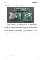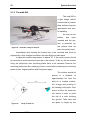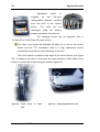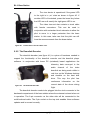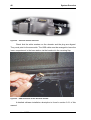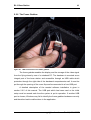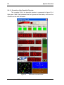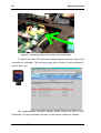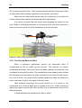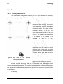
1
USER MANUAL
md4-200
Version 2.2
microdrones GmbH
Siegener Strasse 227
D-57223 Kreuztal / Germany
Phone:
+49 (0)2732 762 115
Fax:
+49 (0)2732 762 150
E-mail:
[email protected]
Table of Contents
Table of Contents.................................................................................... i
List of Figures ........................................................................................ v
List of Tables ........................................................................................ vii
Dual use declaration (legal advice) ...................................................... 1
1 Introduction..................................................................................... 3
1.1
Please Pay Attention!! ...................................................... 3
1.2
History o VTOL .......................................................................... 4
1.3
Technical Details ....................................................................... 4
1.4
Operational Concept of the md4-200......................................... 7
1.4.1 Propulsion Motor and Motor-Controller.................................. 9
1.4.2 Key Components of the In-Flight Electronic ........................ 10
1.4.3 md4-200 Technical Data ..................................................... 11
1.4.4 md4-200 Block Schematic................................................... 12
2 System Overview .......................................................................... 13
2.1
Your md4-200 System / The Components............................... 13
2.1.1 The Remote Control ............................................................ 14
2.1.1.1 Switches, sliders and their Functions............................ 16
2.1.1.2 Assignment of the Joysticks.......................................... 17
2.1.1.3 Selecting an RC Channel.............................................. 18
2.1.1.4 Toggle between Display Settings.................................. 18
2.1.1.5 Resetting the Countdown Timer to 14 min .................... 18
2.1.1.6 Teacher/Scholar Operation ........................................... 19
2.1.1.7 Charging the Accumulators........................................... 19
2.1.1.8 Audible Alarm Signals................................................... 20
2.1.1.9 The Antenna ................................................................. 20
2.1.2 The md4-200 ....................................................................... 22
2.1.2.1 Insert the Accumulator .................................................. 24
2.1.2.2 Assembling the Rotors.................................................. 27
2.1.2.3 Connecting external Servos .......................................... 28
2.1.2.4 The Video Transmitter and its Connection .................... 29
2.2
B1.0 Base Station .................................................................... 31
2.2.1 Functions and Setup............................................................ 31
2.2.2 The Charger ........................................................................ 34
2.2.3 The battery packs ................................................................ 35
2.2.4 The Video visor.................................................................... 37
2.2.5 The Downlink Decoder ........................................................ 39
i
2.2.6 The Frame Grabber ............................................................ 41
2.3
Mobile Video Receiver ............................................................ 42
2.4
Cameras ................................................................................. 43
2.4.1 The Camera Suspension .................................................... 43
2.4.2 Still Photography Camera Pentax ....................................... 44
2.4.3 Video Camera Panasonic Lumix......................................... 45
2.4.4 CCD Daylight Camera ........................................................ 46
2.4.5 Dawn Camera ..................................................................... 47
2.5
GPS including Position Hold ................................................... 48
2.6
Application Software ............................................................... 51
2.6.1 Downlink Decoder............................................................... 51
2.6.1.1 Setup and First Steps................................................... 51
2.6.1.2 Operation of the Downlink Decoder.............................. 58
2.6.2 The Downlink Player ........................................................... 59
2.6.3 The SD-Player .................................................................... 61
2.6.4 FMS (Flight Model Simulator) ............................................. 67
2.6.5 PVR Frame Grabber ........................................................... 70
2.7
System Software ..................................................................... 73
2.7.1 The MD-Dialog.................................................................... 73
3 Handling........................................................................................ 83
3.1
Pre Flight Check List ............................................................... 83
3.2
Physical Effects during the Flight ............................................ 83
3.2.1 The Downwash Effect ......................................................... 83
3.2.2 The Ground Bounce Effect ................................................. 84
3.3
The Take Off ........................................................................... 85
3.4
The Flight ................................................................................ 87
3.4.1 Exercises ............................................................................ 88
3.4.1.1 Rectangular Parcours................................................... 88
3.4.1.2 Rectangular Parcours and Height Variation ................. 89
3.4.1.3 Changing the Heading.................................................. 90
3.4.1.4 The first “Circle”............................................................ 91
3.5
Landing the md4-200 .............................................................. 93
3.5.1 Bringing her down! .............................................................. 93
3.5.2 Post Flight Check................................................................ 93
4 Safety Instructions ....................................................................... 95
5 Troubleshooting ........................................................................... 97
Annex A: Wind and its Scale .............................................................. 99
A.1
A short History of Scales......................................................... 99
ii
A.2
A.3
A.4
Where and How to use them ................................................. 100
Beauforts-Scale in Phenomenons ......................................... 100
Beauforts-Scale in absolute Velocities................................... 102
iii
List of Figures
figure 1:
figure 2:
figure 3:
figure 4:
figure 5:
figure 6:
figure 7:
figure 8:
figure 9:
figure 10:
figure 11:
figure 12:
figure 13:
figure 14:
figure 15:
figure 16:
Figure 17:
figure 18:
figure 19:
figure 20:
figure 21:
figure 22:
figure 23:
figure 24:
figure 25:
figure 26:
figure 27:
figure 28:
figure 29:
figure 30:
figure 31:
figure 32:
figure 33:
figure 34:
figure 35:
figure 36:
figure 37:
"Flying Jeep" Curtis-Wright VZ-7AP .......................................... 4
Étienne Oehmichen No. 2.......................................................... 5
scheme of propulsion for the md4-200 ...................................... 7
the remote control transmitter.................................................... 8
details of a motor unit ................................................................ 9
in-flight electronic, key components......................................... 10
md4-200 block schematic ........................................................ 12
complete md4-200 system in peli case for transport................ 13
hand held remote control transmitter ....................................... 14
tilt of display ............................................................................. 15
association of the trim pushbuttons ......................................... 15
transmitter in console............................................................... 16
motor control............................................................................ 16
shutter control and waypoint teach-in ...................................... 17
assignment of joysticks to movements .................................... 17
the evo9 teacher/scholar cable ................................................ 19
compact loader for the evo9 .................................................... 20
md4-200, ready for take off...................................................... 22
setup for take off ...................................................................... 22
open drone without and with battery pack ............................... 23
support mechanics of the battery pack .................................... 24
detail of battery pack locking mechanism ................................ 24
inserting the battery pack......................................................... 25
unlocking the battery pack ....................................................... 26
mounting the rotor.................................................................... 27
cable attachment for the servo connections ............................ 28
connecting the servos for the camera...................................... 28
video antenna and camera connection .................................... 29
video transmitter and booster in the drone .............................. 29
base station overview .............................................................. 31
external connections on the base station................................. 31
mounting the base station antenna.......................................... 32
connecting the antenna cable .................................................. 32
connection of the LiPo-charger ................................................ 34
The LiPo charger ..................................................................... 34
LiPo battery pack ..................................................................... 35
components of the video visor ................................................. 37
v
figure 38:
figure 39:
figure 40:
figure 41:
figure 42:
figure 43:
figure 44:
figure 45:
figure 46:
figure 47:
figure 48:
figure 49:
figure 50:
figure 51:
figure 52:
figure 53:
figure 54:
figure 55:
figure 56:
figure 57:
figure 58:
figure 59:
figure 60:
figure 61:
figure 62:
figure 63:
figure 64:
figure 65:
figure 65:
figure 66:
figure 67:
figure 68:
on/off switch of video visor ...................................................... 38
dioptrin adjustment of visor ..................................................... 38
control device for the video visor............................................. 39
the downlink decoder .............................................................. 39
downlink decoder mounted ..................................................... 40
USB-connection of the downlink decoder ............................... 40
USB-connection of the frame grabber..................................... 41
components of mobile video receiver...................................... 42
control elements of mobile video receiver ............................... 42
still photography camera ......................................................... 44
high quality video camera ....................................................... 45
daylight video camera ............................................................. 46
high sensitivity "dawn"-camera................................................ 47
intermediate storage for the dome .......................................... 48
sliders for motor control.......................................................... 49
telemetry hardware ................................................................. 51
screenshot of microdrones download page............................. 52
operational indication of the downlink decoder........................ 57
GUI of the downlink decoder................................................... 58
location of the micro-SD card .................................................. 61
mounting location of micro-SD, seen from the edge ............... 62
flight data sets ......................................................................... 64
input window for joystick setup................................................ 69
control applet for PVR ............................................................. 71
record control of the PVR........................................................ 72
connections for software download ......................................... 73
basics of the downwash effect ................................................ 84
the ground bounce effect ........................................................ 85
top view of the imaginary rectangular parcours....................... 88
exercise „variation of altitude“, seen from the side .................. 89
modified rectangular parcours................................................. 90
cricle flight ............................................................................... 91
vi
List of Tables
table 1:
table 2:
table 3:
table 4:
md4-200 technical data ........................................................... 11
technical data of hand held transmitter .................................... 21
technical data of the video unit ................................................ 30
technical data of the downlink receiver .................................... 33
vii
1
Dual use declaration (legal advice)
The md4-200 is a dual-use item which is operated in both military and civil
applications in Germany and the EU. Therefore, the regulations as in
Council Regulation (EC) No 1334/2000 of June 2000 setting up a
Community regime for the control of exports of dual-use items and
technology
apply.
In particular, this defines that an export authorization has to be acquired by the
local authorities, if the md4-200 or its components is to be shipped or exported to
countries, to which no general export authorization is listed in the annex of the
Regulation.
At present, (July 2007) these countries are:
Australia, Canada, Japan, New Zealand, Norway, Switzerland and the
United States of America.
Further information is available at
http://europa.equ/scadplus/leg/en/lvb/11029.html
Microdrones refuses liability in case the user does not comply with these
regulations.
3
1 Introduction
1.1
Please Pay Attention!!
It is in the responsibility of each user to operate the system safely in
order to avoid harming other people or their legal property or encountering
other damages by taking undue risks. The user is liable for a proper
registration of the flying vehicle and the other technical equipment which is
mandatory for its operation. The user must comply with legal regulations
for the use of the md4-200 at each single location of use.
In detail, the legally compliant use of–
the radio remote control, operating in the 35 MHz band,
the video transmitter in the 2.4 GHz ISM band at 200 mW transmitter
output power,
the flight vehicle itself
has to be ensured.
As the legal restrictions—regarding for example:
» the license to take off
» the acceptable maximum flying altitude
» mandatory insurances and
» other related topics
—are distinct for each location of operation, the user alone is liable for
acting in accordance with any relevant laws in this respect!
If the failure to comply with any of the respective regulations leads to
a claim of a third party against the user, microdrones GmbH does not
accept any responsibility for the damages or financial compensations
which may arise thereof.
As an example, the following restrictions apply or Germany:
A casual insurance for the operation of the vehicle has to be contracted!
The video transmitter has to be licensed at the Federal Network Agency!
You will find the contact information in the Internet!
4
Introduction
1.2 History o VTOL
VTOL
denotes
an
acronym for the term vertical
take off and landing. It denotes
the capability of a flight vehicle
to take off and land again in
vertical direction without the
need of a specific runway. By
default, helicopters are classified as VTOL vehicles.
figure 1:
"Flying Jeep" Curtis-Wright VZ-7AP
A so called Quadrocopter (derived from Latin quadrum, quadrangle)
means to be a flight vehicle, which employs four rotors or propellers each on
vertical shafts and mounted in one level on the bodywork. These rotors may then
elevate or tilt the bodywork as well as propel it into any direction with reference
to the pilot’s heading by just controlling their individual thrust. A Quadrocopter is
a special type of helicopter and therefore shares their capability of VTOL. Other
common terms for this type of flight vehicle are Quadrotor or hovering platform. A
flying specimen is shown in figure 1.
1.3 Technical Details
The advantage of this concept is to control the rotation of the bodywork in
each of the three directions by a simple variation of the thrust and therefore the
torque of each of the four propellers, if the direction of rotation for each of them
has been appropriately selected. Complicated swash plates as in a standard
helicopter
or
other
additional
actuators
are
eliminated,
consequently.
Furthermore, in comparison to the aft rotor concept, no drift effect takes place
and asymmetric artefacts due to gyroscopic effects of the main rotor are
eliminated completely.
It does not matter, if the thrust is controlled by variation of the revolutions
per minute or by pitch, i.e. the variation of the blade angle of the propellers. A
sufficient prerequisite for correct operation is a high change rate in the thrust,
user manual md4-200
Technical Details
5
which has to be fast enough. When controlling the rpms, continuous rate gear
boxes or electric motors offer this capability.
In the early days of helicopters a multitude of rotors found their
applications as the engineers could not imagine practical implementation such as
the swash plate for control purposes. The French aviation pioneer Étienne
Oehmichen had been experimenting with rotating wings since 1920, when on
November 11th, 1922 his Oehmichen No. 2 (see figure 2) took off into the air for
the first time. This specimen of an early Quadrocopter used four elastic rotors
which were controllable in their blade angle by abridging via Bowden cables.
figure 2: Étienne Oehmichen No. 2
Besides these basic lifter rotors further eight horizontal propellers were
employed to ensure stability and provide lateral propulsion. This concept was
due to the fact that the sensitivity and precision of the control fort the four main
rotors did not match the physical requirements. The Oehmichen No. 2 may be
regarded as the first reliable VTOL vehicle. It completed more than 1000 flights
and on May 4th, 1924 imposed a record by flying for 14 minutes, bridging more
than 1000 meters on a circular track.
As the swash plate was invented and aft rotor, twin or coaxial concepts
emerged, the quadrocopter type of VTOL was no longer focused by the relevant
engineers. When the common interest for VTOL-vehicles grew in the 1950’s, the
quadrocopters went airborne to their renaissance.
copyright microdrones GmbH, 2004-2007
6
Introduction
Currently quadrocopters are not employed for passenger flights. However,
the concept has been discovered for drones, UAVs or for model helicopters.
Major improvements in the area of embedded electronics, embedded sensing
and material science have inspired and are the foundation for the effectiveness
of these deployments.
Today’s acceleration sensors are so fast and precise, that sudden torque
effects may be easily kept in control automatically. For quadrocopters those are
commonly occurring faster and in larger quantities compared to standard
helicopters. The reason for this is the fact that the centre of gravity of the vehicle
is very close below if not in or above the level of the rotors.
For this purpose piezo electric sensors are used to determine the angular
velocity of the rotors. As an alternative gyroscopes retrieve absolute figures for
the angular deviation from the vertical direction. An embedded system finally
controls the rpms of the four electric motors to stabilize the flight.
As no other moving parts than the motors and their shafts are needed for
the design, this type of quadrocopter is only a fraction as susceptible or
mechanical failures than a classical helicopter, as the complicated swash plates,
linkage rods or rotor domes are just left out.
By employing Lithium-Polymer rechargeable cells with a very efficient ratio
of energy/mass flight durations of up to 30 minutes are achievable at present.
Future improvements, including the use of miniaturized fuel cells, which
are just being developed, promise flight times of several hours.
user manual md4-200
Operational Concept of the md4-200
7
1.4 Operational Concept of the md4-200
While hovering, the rotors, as being
depicted in figure 3, all have the same speed
level. Changing the position in bearing or
altitude is achieved by modifying the speed
level of one or multiple rotors in a coordinated
fashion.
•
Forward or Backward movements are
initiated by tilting the bodywork forward
or backward respectively and accele-
figure 3:
scheme of propulsion for
the md4-200
ration in that direction (Nick)
⇒ Shift the speed level and thus the thrust between rotors A and C.
•
Moving sideways is initiated by tilting around the longitudinal axis and
respective acceleration (Roll)
⇒ Shift the speed level and thus the thrust between rotors B and D.
•
Turing around the vertical axis (Yaw)
⇒ Shift the speed level and therefore the thrust pair wise between A–C
and B–D.
•
Climbing or Dropping (Pitch)
⇒ Adjust the speed level and thrust of all rotors simultaneously.
By merging these basis control instructions all positions and movements
can be implemented. The desired flight level is kept automatically by the vehicle.
This feature is implemented by a temperature compensated, barometric control.
This quadrotor concept, using pair wise counter directional rotors, relies
on the true compensation of the torque at identical speed levels of the rotors. A
tail rotor, compensating the drift and consuming extra power while not providing
extra lift in a conventional helicopter, is superficial here. This results in increased
energy efficiency. Besides, the distribution of the propulsion energy to four rotors
reduces the exposure significantly—serious injuries caused by the md4-200 are
therefore quite unlikely due to the low weight and the low speed levels.
The drone and its motors as depicted in figure 5 are operated
copyright microdrones GmbH, 2004-2007
8
Introduction
maintenance free. The only wear parts in the system are the accumulators. The
front and aft rotors (A–C figure 3) are turning counter clockwise; the side rotors
(B–D in figure 3) operate in clockwise direction. To climb (»Pitch«) all motors are
accelerated identically, to drop the drone means simultaneous, identical
deceleration of all motors.
For example, steering nick to the front, the lift at the aft rotor is increased
and reduced at the front rotor by the same amount. Roll to the left means to
apply the same steering command to the right motor (increase) and the left one
(decrease) in a similar fashion. Yaw to left means the increase in torque on
motors B–D while the torque on A–C is reduced. The total torque now is non
zero and turns the drone to the left.
Note that the absolute sum of thrust over all four motors is kept identical in
each of the manoeuvres.
The drone is controlled by the two joy sticks of the remote control depicted
in figure 4. The right joy stick
controls nick by pushing it
forward or backward and roll
by moving it sideways. The
vehicle is shifted into the
respective
direction without
turning its heading in that
way.
The left joystick controls climbing by pushing it
forward
and
dropping
by
pulling it backward. Pushing
the
left
joystick
sideways
means the command for a
counter clockwise
(left) or
clockwise (right) yaw.
figure 4:
user manual md4-200
the remote control transmitter
Operational Concept of the md4-200
9
1.4.1 Propulsion Motor and Motor-Controller
Each motor of 24-poles has a gross
weight of 40 grams and a diameter of
48 mm. The brushless, external rotor motor
(see figure 5) with 18 slots and 24 magnets
has a fully synchronized commutation.
Each of the motors is supplements
figure 5: details of a motor unit
by three Hall–sensors which indicate the momentary position and turning speed
of the magnets to the control electronics. The embracing control of the motors is
mediated via a controller–area–network (CAN–bus) on which each motor uses a
distinct device address. The joint operation of all components implements a
closed control loop at dynamic which is fast enough to enable the appropriate,
fast control of the motor momentums and therefore the stabilization of the md4200.
The core component of the electronic is formed by the so called IMUmodule (IMU = Inertial measurement unit)–which implements the bearing fixture
and the barometric altitude stabilization.
This device comprises a set of mutual communicating sensors which are
combined in a so called Kallmann filter. A 32bit-embedded controller provides for
a calculation of the requested control vectors in milliseconds intervals. This type
of generic control allows for a basic stabilization of the drones position and
bearing during flight and eases the manual control tasks imposed on the pilot.
copyright microdrones GmbH, 2004-2007
10
Introduction
1.4.2 Key Components of the In-Flight Electronic
figure 6:
in-flight electronic, key components
Above, in figure 6, the connector PCB of the Lithium–Polymer–
rechargeable battery (LiPo–bat) is displayed. The IMU–module (Navigation
Controller (NC)), including heading retrieval, accelerometer and baroaltimeter for
heading and altitude control is shown to the left. The component on the lower
right side resembles the Flight Controller (FC) for interpretation of the RC
commands including a mixer, several safety facilities, motor management and
many other functions.
user manual md4-200
Operational Concept of the md4-200
11
1.4.3 md4-200 Technical Data
number of CfK-rotors
4
diameter of each CfK-Rotor
approx. 360 mm
full height of vehicle
approx. 198,5 mm
lateral dimensions incl. rotors
912,5x912,5 mm
rotor rpm while hovering
approx. 1.800 U/min
propulsion motors
Brushless, external rotors gearless
drive
outer diameter motor
48 mm
number of poles
24
motor control
fully synchronized commutation with 3
Hall–sensors each
embedded controller
2x 32bit
stabilization
bearing
and
altitude2)
(static
and
dynamic acceleration)
receiver
PPM, 12 channels incl. plausibility
check1)
take off mass incl. CCD camera
approx. 680 g
payload
200 grams
power consumption while hovering
max. 25 Watts
Power supply
LiPo 4s1p 2.300 mAh
flight time incl. camera
> 20 minutes
Max. flight time without payload
approx. 30 minutes
1)
sensors in detail:
acceleration, 3 semiconductor micro machines, global magnetism, air pressure, humidity, temperature
2)
Autonomous emergency landing system, i.e. in case of RC loss, low battery power etc...
further features: flight recorder (SD-drive) and GPS-support (position hold and waypoint navigation)
table 1:
md4-200 technical data
copyright microdrones GmbH, 2004-2007
12
1.4.4 md4–200 Block Schematic
figure 7: md4-200 block schematic
user manual md4-200
Introduction
13
2 System Overview
2.1 Your md4–200 System / The Components
Your md4-200 system is composed of two major components. The first is
the drone itself in the custom fitted pelicase. The second is the base station for
ground control which is shipped in its own pelicase, fitted as an insert into the
larger one as shown in figure 8.
Available options are several different camera types, described in section
2.4 and a GPS aided “position hold” software enhancement.
figure 8:
complete md4-200 system in pelicase for transport
14
System Overview
2.1.1 The Remote Control
figure 9:
hand held remote control transmitter
As a hand held transmitter to control the flight of the drone we have
selected the Royal evo 9, manufactured by Multiplex. Its form factor and the
control switchboard are shown in figure 9. This transmitter is equipped with a so
called synthesizer RF-module which enables the selection of any channel in the
35 MHz band without changing a crystal.
user manual md4-200
Your md4–200 System / The Components
15
The display of the Royal evo
9 can be tilted to adjust it for best
readability for the pilot (see figure
10).
The antenna must be fully
unfolded during operation.
Take care to start flying only
figure 10: tilt of display
with a fully recharged battery.
The trim of both joysticks (i.e. the
preset value which is transmitted in the
neutral position) must be set to “ZERO”
or neutral. The scroll bars in the display
of the Royal evo 9 depict the respective
values. The four pushbuttons in cross
configuration below the joysticks (see
figure 9 and figure 11) control these
settings. The neutral position is clearly
indicated in the display and also triggers
a special sound when reached while
doing the adjustment.
figure 11: association of the trim pushbuttons
WARNING!!!
Make sure to take off only while the trim is neutral
If you fail to comply with this rule, the on board
electronic will receive a permanent, non zero control
vector and assume the pilots intervention. This leads
to a deactivation of the GPS-position hold function.
copyright microdrones GmbH, 2004-2007
16
System Overview
The
best
sensitivity
while
controlling the drone is probably reached
when you pick the joysticks with the tips
of thumb and pointing finger. To ease the
handling an optional console is available.
The hand held transmitter is pushed into it
and may then be carried by a strap
around your neck. This frees your hands
from carrying the device and leaves all
figure 12: transmitter in console
the concentration on the control of the
joysticks and further pushbuttons and switches.
2.1.1.1 Switches, sliders and their Functions
When switching the system on, the sliders
„E“ and „F“ of figure 13 need to be pulled back
fully. Pushing „F” to the front is assumed to start
the rotors with one exception:
If the GPS-position hold function is
figure 13: motor control
enabled but the drone has no sufficient GPS
resolution, the start of the engines is blocked for
security reasons. As an exception (e.g. in case of GPS shadowing on ground
level), slider „E“ may be used to override this safety feature. To initiate this
override procedure, “E” needs to be pushed to the front, kept there for a moment
and then pulled back. An acoustic acknowledgement is issued by the drone and
the motor start via “F” is now enabled.
The lever keys „L“, „N“ on top of the Royal evo 9
need to be in the front position, the lever switches „O“ at the
left and „J“ at the right edge of the hand held transmitter
must be in the uppermost position. The latter are still
without any function in the case of a scholar transmitter.
On the teachers side (see 2.1.1.6), the switch „O“
toggles between Scholar control and teacher override. Keeping the switch up by
user manual md4-200
Your md4–200 System / The Components
17
the teacher allows full control of the drone by the scholar. In case of need the
teacher may take back control immediately by flipping switch “O” down.
Switching the motors on and off is the exclusive right of the teacher in any case.
Switch „G“ should rest in the neutral
position, „I“ has to be pulled backwards. Future
revisions of the software will employ “G” for
teach-in operations to the GPS waypoint
system.
Pushing switch „I“ to the front operates
the shutter of the payload camera Video
cameras
will
capture
sequences,
photo
cameras will repeat shutter releases as long as
“I” stays in this position.
figure 14: shutter control and waypoint teach-in
2.1.1.2 Assignment of the Joysticks
The left joystick controls the pitch in the meaning of “climb!” by pushing it
forward and “drop!” by pulling it back. In the neutral position the automatic flight
level stabilization is at work and keeps the drone at the so far predefined altitude.
figure 15: assignment of joysticks to movements
copyright microdrones GmbH, 2004-2007
18
System Overview
Moving the stick sideways turns the drone counter clockwise (to the left) or
clockwise (to the right) around the vertical axis. The joystick on the right side
moves the drone forward (pushing it) or backward (pulling it). Moving sideways
causes the drone to follow in the respective direction with reference to its current
heading.
2.1.1.3 Selecting an RC Channel
To select a specific channel, make sure the transmitter is switched off.
Keep the pushbutton labelled “tools/ABC1“ pressed and turn on power at the
transmitter. Release the button and use the
turn knob above switch “J”/”H” to select the
channel. You finalize this procedure by
acknowledging the selection using the brad
“Enter” key in the middle of the service key
pad. Turn off the transmitter now. The new setting will take effect the next time
power is restored and the transmitter will use the selected channel then.
2.1.1.4 Toggle between Display Settings
To toggle different display settings, the pushbutton in
the lower right corner labelled “/-#0“ has to be pressed.
Different displays, including the battery voltage, trim
settings or a status screen including a countdown timer are
selectable this way.
2.1.1.5 Resetting the Countdown Timer to 14 min
To avoid excessive discharge of the main battery in
the drone the countdown timer of the transmitter is preset to
14 minutes. As soon as the motors are started by actuating
switch “F“ the countdown starts. After the drone has been
landed and the battery has been replaced, the countdown
timer should be reset by pressing „REV/CLR“ to start a new cycle.
user manual md4-200
Your md4–200 System / The Components
19
2.1.1.6 Teacher/Scholar Operation
The Royal evo 9 offers the
capability of a teacher/scholar operation. To enable this mode, two transmitter devices of the type evo 9 are
operated
in
parallel
while
being
connected through a special cable as
being shown in figure 16. The switch
“O” is now operational on the teacher
transmitter to pass control to the
scholar (up) or to the teacher (any
figure 16: the
evo9
teacher/scholar
lower position)
cable
Make sure not to confuse the teacher and scholar side of
the cable
Make sure the transmitters are programmed to the
respective modes. Check the evo 9 operating manual for
further details.
Microdrones GmbH offers specific software which facilitates the
programming of the transmitters to the correct mode. Using this option, a scholar
can be taught by an experienced pilot who can regain control instantaneously
whenever this would be required.
2.1.1.7 Charging the Accumulators
Charging the batteries of the evo 9 is done by means of a separate battery
charger. As soon as the reported
Voltage in the display has come
down to a value of 7.2 to 7.3 Volts,
recharging is highly recommended.
Figure 17: compact loader for the evo9
copyright microdrones GmbH, 2004-2007
20
System Overview
A display containing the charging status can be selected by pressing the
key “/-#0“ repeatedly. Charging overnight is sufficient to recharge the NiMh
battery completely. Use the round DIN connector to plug the battery charger into
the socket in the bottom of the transmitter case. Make sure that you align the
notch on the plug to the corresponding dip in the socket. Do not use excessive
force to press the plug in. The other cable in red and blue on the battery charger
is not in use in the setting of the md4-200 system
2.1.1.8 Audible Alarm Signals
As soon as the transmitter has started the count down, as a consequence
of starting the motors, an audible alarm is issued after each completed minute of
activation.
This signal shall remind the pilot of the time passing by and allows for a
precise timing of the flight schedule. As soon as the 14 minute interval has
expired a permanent alarm sound is generated. It is highly recommended to land
the drone immediately to avoid risks of power failures on the flying drone or
excessive discharge of the LiPo batteries. The latter must be changes
immediately after the drone has touched down.
2.1.1.9 The Antenna
Make sure the antenna of the transmitter is extruded completely during
the flight. Do not let the antenna point towards the drone as this setting
minimizes the effectiveness of the radio link and reduces the coverage range. It
is more efficient to align the antenna perpendicular to the line between the pilot
and the drone. To achieve a reasonable general setting, the fully extruded
antenna may be tilted upwards by first dragging smoothly at the base and then
swinging it upwards.
user manual md4-200
Your md4–200 System / The Components
21
transmitter ROYAL evo 9, using 6/1800mAh NiMH rechargeable batteries,
th i
HF
d l HFM
S
modulation:
FM/PPM
10 kHz-steps
servo impulse format:
MPX 1,6 +/- 0,55 ms
UNI 1,5 +/- 0,55 ms
power supply:
operational
consumption:
6 Zellen NiMH, Mignon (AA)
current approx. 20 mA (w/o HF)
approx. 165 mA (incl. HFM-4)
approx. 190 mA (incl. HFM-S)
weight:
approx. 900 g (including battery pack)
dimensions (l x w x h):
220 x 200 x 60 mm
table 2:
technical data of hand held transmitter
copyright microdrones GmbH, 2004-2007
22
System Overview
2.1.2 The md4-200
The md4-200 is
a light weight vehicle
constructed by carbon
fibre and thus requires
appropriate and careful handling.
As soon as the
battery
has
been
inserted and the system is powered up,
the vehicle must not
figure 18: md4-200, ready for take off
been moved by hand.
Immediately after landing the battery has to be removed and must be
replaced by a fully charged one before the next flight can take place.
In case the outdoor temperature is above 15° C the motor covers should
be removed to avoid excessive heat ups in the motors. To do so, the two screws
fixing the aluminium rotor mounting plates have to be released. Remove the
mounting plates and the underlying motor covers before restoring the mounting
plates in their original position and fixing them again.
The vehicle should be
placed
in
a
distance
of
approximately 5m from the
pilot on a levelled surface,
the orange arm pointing in
the heading of the pilot. If the
drone is tilted, the electronic
will refuse to start to avoid
the risk of a rotor touching
the ground. Take care that
figure 19:
setup for take off
user manual md4-200
not grass is caught by the
Your md4–200 System / The Components
23
rotors and strangles the motors.
Keep all in flight positions in an 80° sector in front of your body.
Avoid flying besides or above yourself
In particular beginners will be unable to cope with such a demanding
situation. Even more complicated and therefore to be avoided is the so called
reverse hovering. In this case, the drone has been rotated by approximately 180
degree from the take off position, the orange arm pointing towards the pilot. In
this situation, all controls appear to be inverted! The situation needs great care,
experience and a sufficient training on the FMS (see section 2.6.4).
As usual operation of the drone does not require flying in this position, it is
highly recommended to avoid it and the accompanying high risk due to the
demanding prerequisites in coordination.
figure 20: open drone without and with battery pack
When fitting the dome on top of the drone, align the two orange arrows
and close the cover. The vehicle should be held with one hand at the aft arm
while the other hand should turn the dome counter clockwise smoothly until you
copyright microdrones GmbH, 2004-2007
24
System Overview
feel it snapping into its fixture. The open dome may be hooked below the battery
level to avoid stress on the GPS antenna cable.
Always take care not to disconnect the GPS antenna cable accidentally
while dismounting the dome.
2.1.2.1 Insert the Accumulator
The battery pack
of the md4-200 is aligned
by
the
lateral
guides
shown in figure 21 and
thus kept in the correct
position.
The
battery
pack has 2 lateral fins
which need to lock with
the guides in the body
work.
figure 21: support mechanics of the battery pack
Place the battery
pack between the 2 guide
rails and slide it slowly
forward until it locks with
the guides as shown in
figure 22.
figure 22: detail of battery pack locking mechanism
You must never place the battery pack in wet grass or put it into you
pocket together with a key ring or some coins.
user manual md4-200
Your md4–200 System / The Components
25
The battery pack is extremely sensitive to short circuit situations. In the
worst case a short circuit may cause inflammation of the battery pack.
Temperature of more than 2000° C may occur. The potential damage
is enormous.
In case of fire you must not try to extinguish the fire with water. This
would lead to an explosion. If you feel the battery pack hearten up,
leave it on a solid surface and stand clear. You may cover it with sand
if available.
All manual operations on the drone, e.g. opening the dome or swapping
batteries, should be carried out by the pilot while standing behind the vehicle.
The front, orange arm points away from the pilot. One hand grabs the aft arm,
the other hand performs the operation.
While
inserting
the battery pack, the
correct locking o guides
and
fins
has
to
be
checked.
figure 23: inserting the battery pack
copyright microdrones GmbH, 2004-2007
26
System Overview
When
removing
the battery pack, the
locking
back
latch
side
on
the
can
be
pressed down with the
thumb
as
shown
in
figure 24. The other
hand gently pushes the
battery pack backwards.
figure 24: unlocking the battery pack
user manual md4-200
Your md4–200 System / The Components
27
2.1.2.2 Assembling the Rotors
The md4–200 operates four rotors,
two of which turn clockwise and the other
two counter clockwise. Each rotor has two
knobs on its bottom of the centre bar
which are matched by two holds in the
rotor mounting plate.
To avoid accidental misplacement,
both directions of turning use individual
distances between these knobs.
When mounting the rotors, the
motors must be supported by one finger
being pushed inside the bottom hole of the
motor pod. If you press too hard from the
top without support, the risk is to press the
motor frame out of the carbon fibre
reinforced plastic (cfrp) pod.
Make sure that the centre bar is
level with the top of the mounting plate
before you proceed. The rotors are
secured by two O-rings of rubber. As
rubber wears off, check each ring for
proper elasticity and make sure there are
no fissures in it.
If new rotors are used ridges
around the knobs may hinder the correct
fitting. In this case, use a fine file to
smoothen the ridges to make the rotors fit
nicely.
In case of an accident, in which the
rotors have hit any obstacle, a thorough
figure 25: mounting the rotor blades
copyright microdrones GmbH, 2004-2007
28
System Overview
check of the rotors is mandatory to avoid further mischief by breaking during
flight. Besides a visual check for small fissures or ridges the rotor should be
picked at the centre bar with two fingers while the other hand gently bends down
the rotor tips. If a rotor is damaged, it will break completely in this test while a
stable one will show no effect.
2.1.2.3 Connecting external Servos
On the bottom side the drone shows two 3-pin connectors which protrude
through a rectangular hole in the sponge rubber.
figure 26: cable attachment for the servo connections
All plugs must be inserted with the orange cable heading towards the
orange front arm of the drone.
Connector 1 serves to control the
tilt of the camera while connector 2 is
used to activate infrared link of the
remote shutter release.
Make
sure
that
each
servo
connector is right in place, not being
shifted to one side or the other before
you insert a battery pack into the drone.
Never attach or detach the servos
while power is on!
figure 27: connecting the servos for the camera
user manual md4-200
Your md4–200 System / The Components
29
2.1.2.4 The Video Transmitter and its Connection
Each
camera
has
been
equipped with a female connector to
provide a live video signal. If the
option “video transmitter” is mounted
within the drone, a mating plug and
an antenna cable can be accessed
at the bottom of the drone. Figure 28
depicts the video antenna fort he live
figure 28: video
antenna
and
camera
connection
signal and on the right side the plug
and socket for the video data link in
order to identify them in your system.
The
video
transmitter
itself is visible at the
bottom side of the drone.
The
two
small
PCBs shown in figure 29
incorporate the genuine
sender, delivering 10 mW
(10dBm) and a matching
booster to power up the
RF signal to a level o
200 mW (23dBm)
16 different channels
may
be
selected.
Drones are delivered with
settings of either channel
4, 8, or 12.
figure 29: video transmitter and booster in the drone
copyright microdrones GmbH, 2004-2007
30
System Overview
Mikro-Transmitter for Video and Audio Signals
frequency range:
2,3 - 2,5GHz
channels:
16 (channel selector switch)
transmit power
10mW (10dBm EIRP)
video input:
1Vss ± 0,1Vss @ 75Ohm
video bandwidth:
30Hz - 5MHz
audio input:
microphone input with AGC
audio bandwidth:
30Hz - 15kHz
power supply:
5,5 - 7,5V DC
dimensions:
18 x 18 x 13mm (w/o antenna)
mass:
10g
Mikro-Booster for Mikro PLL Transmitter
frequency range:
2,3 - 2,5GHz
transmit power
200mW (23dBm EIRP)
HF-input:
Mini-Coax, 50Ohm
HF-output:
Mini-Coax, 50Ohm
power supply:
5,5 - 7,5V DC
dimensions:
18 x 18 x 13mm
mass:
5g
features:
» increases the transmit power to 200mW
table 3:
technical data of the video unit
user manual md4-200
B1.0 Base Station
31
2.2 B1.0 Base Station
2.2.1 Functions and Setup
The
depicted
base
in
station
figure
30
combines multiple functions.
Most important it is a receiver
station for the video and
telemetry data sent out by the
drone. The received signals
are decoded and prepared for
use in a standard notebook as
working platform. In addition,
the base station serves as a
charger unit for the LiPo
rechargeable batteries.
figure 30: base station overview
Include in the base
station is a 3–way video splitter which sends
one output to the frame grabber device (see
2.2.6) which enables post processing and
live images on a PC. This connection is set
up by an USB–cable which you find below
the large flap on the left of the base station.
The other outputs are available on the
switchboard
at
two
independent
Cinch
sockets. The supplied video visor will pick it
up here. Alternatively, a beamer or a
camcorder may be attached to display
and/or capture the video live stream. The
video signal is PAL compliant at 720 x 576
pixels @ 25 frames per second.
figure 31: external connections on
the base station
copyright microdrones GmbH, 2004-2007
32
System Overview
The base station may get its own power supply from three sources,
namely power mains at a voltage of 100–240 Volts AC, 12V DC vehicle power
from a car or, finally, from the same battery packs which power the drone. The
LiPo battery packs may be used as power source (red cable below the flap) or
themselves being recharged if one of the two other power sources are in
operation.
ATTENTION: New vehicles, vans or lorries my supply other DC
voltages than 12V. To avoid permanent damage, consult the
operations manual of your vehicle before connecting to the 12V
DC inlet. To not tamper with the adapter cable to make it connect
to inappropriate power outlets.
To prepare the base
station for operation, the
antenna has to be mounted
by inserting the foot piece
figure 32: mounting the base station antenna
in the slot on the cover of
the pelicase (figure 32) and
screwing tight the antenna
connector on the switchboard (figure 33).
figure 33: connecting the antenna cable
user manual md4-200
B1.0 Base Station
33
Select and activate one of the three available power sources (100-240V
AC, 12V DC or LiPo battery pack) before your switch on the base station. An
LED besides the power switch will indicate the selected power source.
The two buttons below the 7-segment display are used to select a video
channel matching to the setup of your drone. This step has to be repeated only
in case of operating different drones from the same base station.
The live video signal (which also bears the telemetry data in the audio
channel) is now available at the frame grabber output and at the cinch sockets.
The installation of the appropriate user software for the frame grabber and the
downlink decoder is covered in section 2.6.
Technical Data of Receiver
frequency range:
2,3 - 2,5GHz
channels:
16 (selector switch)
video output:
1Vss ± 0,1Vss @ 75Ohm
video bandwidth:
30Hz - 5MHz
audio output:
500mWeff an >1kOhm
audio bandwidth:
15Hz - 16kHz (3dB)
power supply:
7 - 30V DC
dimensions receiver:
117 x 68 x 35mm (w/o antennas)
dimensions diversity box:
80 x 68 x 32mm (w/o antennas)
mass of receiver:
230g
mass of diversity box:
120g
features:
» external diversity box using 4 antennas
» audio stereo channel indicator
» switching channel
» indication of relative receiver signal strength
» video image inversion
» automatic channel switch
» video and audio mute option
» 5V output for antenna preamplifier
» video detect output
table 4:
technical data of the downlink receiver
copyright microdrones GmbH, 2004-2007
34
System Overview
2.2.2 The Charger
Recharging the batteries
is applicable only if the base
station is powered by mains or
by the 12V DC vehicle power
inlet. In this case, the LiPo
battery
pack
has
to
be
connected to the two lead sets
shown in figure 34 which are to
be found in the inside of the
base
station
pelicase.
After
having connected the battery
figure 34: connection of the LiPo-charger
pack power supply (seen on the
right in figure 34) it is mandatory
to connect the so called balancer cable in parallel. The latter is required to
ensure the proper equalization of the voltage level in all the cells of the battery
pack. Make sure that the power on switch (see figure 35) of the charger unit is
turned on (position “1”) only after both cables are fitted securely.
In a power on check all three LEDs of
the display turn on immediately. While
charging, the yellow LED remains on to
indicate the status “operating”.
In case the red “Error” LED remains
activated, please check the balancer cable
connector at the compartment wall. As a
result of vibrations during transport it might
have come loose. Having fixed this problem,
turn off the charger and switch it back on
again.
figure 35: The LiPo charger
At most one hour of charging is
sufficient to complete the recharge process.
user manual md4-200
B1.0 Base Station
35
Switch off the charger and unplug the battery back before putting it back to its
storage position.
In case you do not intend to use the batteries for quite a while, do not
recharge them completely but leave them at approximately 70% of charges
capacity.
Make sure that the battery back has cooled down completely after use
before it is recharged!
Do not charge LiPo batteries unattended!
2.2.3 The battery packs
The use of Lithium Polymer rechargeable batteries is mandatory due to
the weight restrictions of the drone. Because of deviations in the manufacturing
process the impedance of the battery cells varies as well as the capacity
between individual exemplars. To ensure a constant high quality of the battery
packs, microdrones selects each cell and matches the set for each battery pack.
Do never ignore the „low battery“ warning reported by the base station,
even if the flight is still shorter than 20 min in some cases. Temperature
and wind conditions may have used more than average energy from the
cells.
Figure 36 shows a LiPo bat-md4-200
rechargeable battery pack. It is assembled from 4
individual cells of 14.8 Volts and offers a capacity
of 2300 mAh.
This battery pack is used in the md4-200
system to power the drone itself as well as to
operate the base station.
figure 36: LiPo battery pack
The recharging can be done in the base
station (see 2.2.2) or by a special charging device
offered by microdrones.
All battery packs are operational at room temperature only. If a battery
pack has low temperature, e.g. after a night in the booth of a car, they have to be
warmed up slowly to 20–40° C at least 3 hours before use. A simple way to
achieve this is to carry them in the inner pocket of your jacket close to the body.
copyright microdrones GmbH, 2004-2007
36
System Overview
You must avoid a short circuit of the contact elements.
This can happen even by some coins in your pocket, a key ring or by
leaving the battery pack in grass wetted by rain or dew! Long term storage
should be planned ahead as the battery pack should be charged to 75% of the
maximum level only for this case. The value displayed by the meter at the base
station (in battery pack operation) or the charge level indicator of the downlink
decoder give easy access to this information.
If, during a flight, the „battery low“ warning is issued, the drone has to be
landed at once!
Even if this warning is followed by a „battery ok“ message, the general
condition has not changed. A sudden drop of the wind speed may have
led to a temporal rising of the battery voltage. The „battery low“ warning
must lead to immediate landing and an exchange of the battery pack!
Directly after the landing the battery pack has to be taken from the
drone at once.
You should avoid keeping the drone in the sunshine when not flying. This
would cause a heat up of the drone and consequently can violate the specified
maximum operational temperature of the embedded electronic and thus cause
malfunctions!
Take off is allowed only after insertion of a fully charged battery pack!
Make sure to distinguish fully charged from partial discharged battery packs by
storing the first kind in the upper compartment of the sponge rubber tablet and
the others in the lower section. This handling strategy avoids accidental
confusion.
Most crashes and harsh landings are caused by taking off with a partially
discharged battery pack!
New battery packs do not offer the full capacity at once but they “learn”
their capacity during the first 10 recharge cycles. Thus, flight times with new
battery packs should never be extended beyond 10 min. Do not forget to start
the recharge only after the battery pack has cooled down completely after flight.
user manual md4-200
B1.0 Base Station
37
Battery packs which are not subject to complete discharging will provide
substantially more charging cycles in their lifetime. Take care to recharge the
battery packs regularly to avoid such a “deep discharge” situation. This is a
further reason to recommend flight times well below the 20 min limit. The 14 min
duration as being programmed in the hand held transmitter has proven to be a
reliable value to initiate the landing procedure.
2.2.4 The Video visor
figure 37: components of the video visor
The video signal is input
into the visor by the yellow plug
which has to be inserted into
one of the video outputs of the
switchboard.
plugs
(audio
The
other
input)
two
remain
unused.
copyright microdrones GmbH, 2004-2007
38
System Overview
Operational
supplied
by
power
two
is
AA–type
rechargeable batteries inserted
from the back of the control
device.
The
recharged
cells
using
the
can
be
battery
charger included in the visor set.
The charging device can be operated from a
12 Volts DC or a 230 Volts AC power source.
The video visor should be switched off while not in use as the control
device and the TFT illumination lead to a high operational current
consumption and lead to a fast discharge of the cells.
The on/off switch is located at the edge of the control device (see figure
38). To adapt to the visus of your eyes the visor provides a white slider at the
bottom on each side of the housing as shown in figure 39.
figure 38: on/off
switch
visor
user manual md4-200
of
video
figure 39: dioptre adjustment of visor
B1.0 Base Station
39
The visor device is operational if the green LED
to the right is in „on“ state as shown in figure 40. If
another LED is illuminated, press the broad key below
the LED row until exactly the right green LED is on.
The video visor set also contains a cinch cable
with
female
connectors.
This
can
be
used
in
conjunction with a standard cinch extension to allow the
pilot to move in a larger perimeter from the base
station. In this case, take care that the pilot can still
here the announcements from the base station.
figure 40: control device for the video visor
2.2.5 The Downlink Decoder
The downlink decoder (see figure 41) is a piece of hardware needed to
support the functionality of the downlink recorder and the downlink player
software. In conjunction with these PC (notebook) based applications the
telemetry data conveyed in the
audio
channel
of
the
video
downlink are being made visible in
real time on the Windows desktop
and storable on the hard disk
drive. This way the pilot has
continuous
figure 41: the downlink decoder
information
on
the
current state of the drone during
flight.
The downlink decoder needs to be plugged into the cinch connector in the
backward compartment of the base station where the antenna is stored when not
in operation. The 6-pin connector on the other side will be connected to the
multifunctional cable. The 5-pin socket on the top side enables future software
updates and is unused currently.
copyright microdrones GmbH, 2004-2007
40
System Overview
figure 42: downlink decoder mounted
Check that the white markers on the decoder and the plug are aligned.
They must point to the same side. The USB cable must be arranged to leave the
lower compartment in the base station via the breakout in the covering flap.
figure 43: USB-connection of the downlink decoder
A detailed software installation description is found in section 2.6.1 of this
manual.
user manual md4-200
B1.0 Base Station
41
2.2.6 The Frame Grabber
figure 44: USB-connection of the frame grabber
The frame grabber enables the display and the storage of the video signal
from the flying drone by use of a notebook PC. The hardware is mounted as an
integral part of the base station and accessible through an USB cable which
protrudes through the right side of the backward compartments wall. It must be
put through the opening of the cover flap and be connected to a free USB port.
A detailed description of the needed software installation is given in
section 2.6.5 of this manual. The USB port which has been used or the initial
setup must be reused each time the system is put to operation. If another USB
port is chosen, Windows may fail to identify the frame grabber hardware correctly
and therefore lead to malfunctions in the application.
copyright microdrones GmbH, 2004-2007
42
System Overview
2.3 Mobile Video Receiver
The mobile video receiver enables the decoding and live watching of the drone’s
video signal independent from the base station. As this equipment lacks all off
the safety features—which are
enabled by the base station and
the
downlink
decoder—the
mobile video receiver is no cheap
replacement for the base station.
Its function is rather a supplement to allow the pilot to move
freely and concentrate on the
flight and the picture taking while
figure 45: components
of
mobile
receiver
video
a partner controls the base station
telemetry.
The mobile video receiver
includes an identical copy of the video visor contained in the base station. The
mobile video receiver is powered by the same LiPo battery packs which are used
fort the drone and the base station.
figure 46: control elements of mobile video receiver
user manual md4-200
Cameras
43
2.4 Cameras
2.4.1 The Camera Suspension
Each camera type which is offered by microdrones is accompanied with a
specific mounting frame which makes the camera an integral part of the md4200. All mounting frames are constructions from cfrp. Each is hooked to a
common support at the bottom of the drone. To make the mounting process easy
and in order to save weight, any locking mechanism has been sacrificed. The
gravity of each camera is used to keep the construction tight in the hinges. (This
works fine as the md4-200 is not capable to do a looping.)
Do not turn the drone upside down once a camera is attached. The
camera might fall out and crash.
All mounting frames are equipped with a remotely controlled servo motor
to tilt the optical axis of the camera lens from a horizontal position by 90 degrees
to a straight vertical direction.
You must not try to change the tilt of the camera by hand. The fragile gear
box of the servo motor would inevitably get destroyed by such a handling!
To control the angle of tilt by the remote control, press the push button „H“
on the lower right edge of the hand held transmitter and use the left joystick. The
„pitch” function is no replaced by the camera tilting function while “H” is pressed.
Pulling back the joystick will raise the lens of the camera, pushing the joystick
forward makes the lens look down.
Make sure not to forget pressing „H“ permanently during the procedure as
the result would be a climbing o falling drone. The proper connection of the servo
connection is described in detail in section 2.1.2.3.
copyright microdrones GmbH, 2004-2007
44
System Overview
2.4.2 Still Photography Camera Pentax
The Pentax Optio A 30
delivers
high
quality
still
photographs as a resolution of 10
mega pixels is provided.
The shutter is controlled by
an infrared control at the front of
the camera. The shutter is released by pushing the switch „I“
to the front.
Keeping the switch in this
position
will
cause
repeated
snapshots as long as the process
figure 47: still photography camera
is not stopped by pulling “I” back
again.
The picture which is usually displayed on the LCD screen on the back side
of the camera is switched off and transmitted in real time via the connected AVcable and the video transmitter to the base station and thus allows the selection
of scene.
The mounting frame compensates roll of the drone around the longitudinal
axis. Self amplification of oscillations is prevented by an integrated damper.
Check the camera battery and free storage capacity on the camera’s SD card
before take off.
The proper cabling of the servo connections for tilt control and shutter
control is described in detail in section 2.1.2.3.
user manual md4-200
Cameras
45
2.4.3 Video Camera Panasonic Lumix
The Panasonic Lumix has
been selected in favour of its high
quality video capture facility to
produce onboard videos.
The resolution of the video
clips is 848x480 pixels at a frame
rate of 30 frames per second. The
output format is QuickTime *.mov.
In contrast to the other
cameras the shutter is released
manually by the pilot before take
off. Take care not to point to an
object very close while switching
figure 48: high quality video camera
the camera on because this
would shut off the auto focus. The
resulting pictures would be blurred in that case during the flight.
The video file is stored on a camera internal 1 GB SD card.
The mounting frame compensates roll of the drone around the longitudinal
axis. Self amplification of oscillations is prevented by an integrated damper.
Check the camera battery and free storage capacity on the camera’s SD card
before take off.
The proper cabling of the servo connection for tilt control is described in
detail in section 2.1.2.3.
copyright microdrones GmbH, 2004-2007
46
System Overview
2.4.4 CCD Daylight Camera
The CCD daylight camera is a designated video camera without internal
storage capacity. Due to this a separate battery is not needed while the video
stream is sent live to the base station.
The focus of the camera is fixed. To capture the video in a file the use f
the frame grabber software is mandatory. The mounting frame does not
compensate roll of the drone.
figure 49: daylight video camera
user manual md4-200
Cameras
47
2.4.5 Dawn Camera
figure 50: high sensitivity "dawn"-camera
The twilight or dawn-camera is a specialized video camera for use in a low
luminosity environment even at night time. This high sensitivity camera is
operable at luminosities of 0.0003 Lux.
The camera is dedicated for live streaming. No storage media or battery
pack is included. The video image is streamed live to the base station. The focus
of the camera is fixed. The recording is done by the frame grabber application on
the notebook.
copyright microdrones GmbH, 2004-2007
48
System Overview
2.5 GPS including Position Hold
The GPS–position hold option employs the Global Positioning System
(GPS) to stabilize the drone during the flight and to keep the absolute position
close to a spot autonomously.
The pilot therefore is freed from the flight control for a while and may
concentrate fully on the operation of the camera. The GPS antenna is an integral
part of the upper dome of the
drone’s body.
When
dome,
detaching
take
care
the
not
to
disconnect or even tear off the
GPS connection cable.
The dome has to be
turned counter clockwise until
the two orange arrows are
aligned and can be taken off
with care now. It may be fixed
by sliding it under the battery
pack
locking
mechanics
as
shown in figure 51.
The
GPS
subsystem
indicates its status by audible
beeps. Just after power up a
slow
figure 51: intermediate storage for the dome
sequence
of
beeps
indicates the search for the GPS
satellite signals. As the quality
of the satellite information increases, i.e. if 4 or more satellites are readable and
the precision of the location estimation has improved, the beeping shortens its
rhythm. After a short while (depending on the situation 30s or more are possible),
the rhythm changes to twin beeps. Even before that the downlink decoder will
report “GPS ok” and display the number of received satellites (SV, space
user manual md4-200
GPS including Position Hold
49
vehicles) and a–hopefully decreasing–figure or the mean position deviation in
meters.
The twin beep signal indicates the “ready for take off” status o the drone in
which the engines may be turned on. To avoid problems in this procedure the
following precautions should be taken:
Move away at least 5 meters from the system after having inserted the
battery pack, closed the dome and putting the md4-200 to its take off
position.
If you do not stay clear of the drone or pull out the RC antenna in this
phase, the RC signal may jam the satellite reception!
After the twin beep attention has settled to a steady rhythm in GPSposition hold mode, the engines may be turned on by pushing the slider “F” (see
figure 52) to the forward position. Keep the left joystick pulled back to the limit to
avoid and accidental take off.
figure 52:
sliders for motor control
If the system works all right, the drone utters a „melody“ of acknowledge
beep and the rotors start turning. Now it is time to pull out the antenna
completely. You should tilt up the fully extended antenna by gently pulling at its
base to unlock the mechanical lock and then swing it upwards.
If there is any problem, i.e. the drone may have lost the sufficient satellite
signal before the motors are started, the rotors stand still. The drone reports a
fast series of beep as an error indication. In this case, slide back “F” and wait
again or a while. You can not take off just now!
copyright microdrones GmbH, 2004-2007
50
System Overview
In case this problem persists, two options are available:
1. Open the dome, disconnect the battery first and the GPS sensor
afterwards. Now re-insert the battery. The GPS-position hold option
is deactivated after the power up and you may start at any time.
2. An override of the take off blocking safety routine is possible. To do
so, push slider “E” to the front and pull it back about 2 seconds
later. This will switch off the safety check. The engines are unblock
a may be powered on by the above procedure. The drone will try to
derive its position during flight time.
The second option should be used only as a rare exception. If the drone
regains sufficient position information during the flight, this might result in
a sudden yaw as a result of the alignment procedure.
user manual md4-200
Application Software
51
2.6 Application Software
The application software introduced in this section is designed to operate
on WIN XP Service Pack 2. Other operating systems have not been tested and
may cause malfunctions.
2.6.1 Downlink Decoder
2.6.1.1 Setup and First Steps
To operate the telemetry option of the
downlink, hardware components are required as
indicated (summarized in figure 53):
● Multifunctional cable USB to serial
● Downlink decoder hardware
● Audio cinch connector in the base station
backward compartment
The files “USB_Driver” and the he
figure 53:
telemetry hardware
application „Downlink_Decoder r1.0“ need to be
loaded
from
the
microdrones
web
page
(see
figure
54)
in
the
“downloads/software” section.
copyright microdrones GmbH, 2004-2007
52
System Overview
figure 54:
screenshot of microdrones download page
Download the USB driver as a first step and unzip the file to a directory of
your choice. Double click on the executable file to install the driver.
You may also double click on the file entry in the archive to do so. The
successful completion of the operation is indicated by a message box.
user manual md4-200
Application Software
53
You may now connect the USB cable to a free port on the notebook.
Window will remember the USB port. Use the same port each
time fort he downlink decoder!!
Windows detects the new hardware automatically and reports the
progress of detection and registration via legend entries at the tray.
You may either remember the COM port index which is shown during auto
detection of check in the system manager, which new COM port has been
activated. Move your mouse to the “my computer” symbol on the desktop or in
the start section. A right click on the symbol opens a drop down menu from which
you select “properties”.
copyright microdrones GmbH, 2004-2007
54
System Overview
Move to the „hardware“ register in the „system properties“ dialog and hit
the button „device manager“
The device manager application pops up and lists the information on the
available system devices. Navigate to the entry Ports (COM & LPT) and unfold
the tree at this node by clicking on the plus (+) sign. You will find an entry
labelled USB Serial Port, which showed an assignment to COM4 while the
screenshots for this manual were taken.
user manual md4-200
Application Software
55
Remember the COM port number and connect the downlink decoder
hardware of the multifunctional cable.
Make sure to align the white
marker at the cable and the
downlink decoder hardware.
Connecting correctly at
this point should result in the
blue LED on the downlink
decoder to switch on
Complete the chain by plugging in
the cinch connector in the cabinet.
copyright microdrones GmbH, 2004-2007
56
System Overview
Having
hardware
downlink
completed
installation
decoder
the
the
application
may be installed. This is done by
unpacking the respective archive
to a folder of your choice.
After
unpacking,
that
folder should contain the files
shown on the left.
» Launch the application by double clicking on Downlink_Decoder.exe.
» Press the “Setup” button as a first step.
» Select the correct number of the COM port for communication in the
radio button group.
» Make sure that the battery warning level is set to 14.0000 Volts.
o Dropping to or below this limit during operation will cause the report
of the „Battery low!!“ warning.
» Press „OK“ to finish the setup procedure and start the operation by
clicking the switch to the „COM ON“ position.
The indicator field „Decoder“ should present a green colour now while all
the other indicators remain olive and tell “inactive” by that. This status is depicted
in figure 55.
user manual md4-200
Application Software
figure 55:
57
operational indication of the downlink decoder
As soon as the battery pack has been inserted into the drone, the RC
control is switched on and the GPS receiver has found space vehicles to read
from, all status indicators switch to light green. The indicator or “machine” is
unused and therefore idle still.
In this case the LED on the downlink decoder hardware will be on
continuously.
It takes a while for the drone to find at least 4 satellites and to derive the
current location at a reasonable precision. This is a prerequisite to achieve the
“ready for take off” status in GPS–Position–Hold mode.
The base station will report „GPS ready!“ when the drone’s receiver has
detected its first connection. Be patient, the “ready for take off” status will take a
bit more time to be confirmed and the drone will acknowledge this with a “beepbeep” sound. Half a minute should be enough for deriving a reliable data
connection with the GPS satellites.
copyright microdrones GmbH, 2004-2007
58
System Overview
2.6.1.2 Operation of the Downlink Decoder
The complete GUI of the downlink decoder is represented in figure 56. A
light green “Data” field indicated that the figures and the battery level are live
values from the md4-200 status.
figure 56:
user manual md4-200
GUI of the downlink decoder
Application Software
59
» The „Operating time“ lists the time which has passed since the battery
pack has been inserted.
» The „Flight time“ counter starts to run as soon as the slider „F“ has
been pushed to the forward position.
» The „Space Vehicles“ display denotes the number of satellites from
which a valid GPS signal can be tracked. A number of four satellites is
the absolute minimum for successful operation of the GPS-position
hold option
» The „Temperature“ display reads the temperature inside the bodywork
of the drone.
Keep an eye on the voltage display!
Make sure that the battery warning level has been set to 14 Volts in the
setup section of the application!
It is an imperative to land the drone when the „Battery low!“ warning is
issued. Further “battery ok” message must be ignored as they are due
to short lived temporal improvements!!
2.6.2 The Downlink Player
The downlink decoder includes a record facility which can be activated by
pushing the „record“ button.
The live displays of the downlink decoder will be dumped into a file if this
option is activated. By doing so, a complete protocol of the flight will be available
for an ex post analysis. All status information and all control vectors being
received from the RC link will be contained in that file.
copyright microdrones GmbH, 2004-2007
60
System Overview
Recoded files will have the extension “*.ddf” as for Downlink Decoder File
To replay these files, the downlink player software is used.
The downlink player is available at the microdrones download site in the
web as indicated in figure 54. Unzip the archive and install the application
analogous to the downlink decoder.
user manual md4-200
Application Software
61
2.6.3 The SD-Player
The md4-200 is equipped with an on board flight recorder in form of a
micro SD card which operates similar to the well known black box in an airliner
and stores all relevant flight data including the commands received via the RC
link.
The SD card is placed, slightly hidden, on the bottom side of the flight
controller PCB (see figure 6 for identification) as indicated by the green arrows in
figure 57 or figure 58 respectively.
figure 57: location of the micro-SD card
copyright microdrones GmbH, 2004-2007
62
System Overview
figure 58: mounting location of micro-SD, seen from the edge
To detach the micro SD card press slightly against the outer edge of the
card with the forefinger. The card gives way and unlocks on being released. It
may be taken out.
The supplementary micro-SD adapter should enable the use in most
notebooks. To read and display the date, the SD-player software is needed.
user manual md4-200
Application Software
63
Having downloaded the software from the microdrones download page
and having unzipped it, just start the SD-player without any further installation.
Click on "Open" to find the dialog below.
copyright microdrones GmbH, 2004-2007
64
System Overview
Select the card drive and check the available data sets, one for each
recorded flight. The ordinal number in the first column is an index, starting at 16
for the most recent flight down to “0” for the oldest available one. Select the
appropriate data set and press “OK” to view the content.
As the data has been written directly to the logical sectors of the file
system, the windows explorer will show a „_DATA.txt“ file as the only and
unintelligible entry.
You must never store data to the micro SD-card with a
conventional file system.
Such an operation would destroy all flight records.
If you desire to extract the flight data to a separate file for documentation,
press „Write“ in stead of „OK“. You will be prompted for a sector from which to
start.
The start sector is marked in red in
figure 59. Omit the leading zeros. Press
“OK” now
You will be prompted for the
terminal sector now, marked green in
figure 59.
figure 59: flight data sets
Pressing „OK“ again will lead you on to the well known „save“ dialog of
Windows.
user manual md4-200
Application Software
65
You must not try to save on the micro-SD card to avoid
destruction of the light data
The output file is named “*.sdf“ and may be distributed in the usual ways,
e.g. being sent per e-mail.
Clicking the „OK“ button in the dialog of figure 59 opens the flight data set.
The flight data is now available for a timed replay, giving full coverage of all
status and control data values in a specific moment. In addition, the deducted
light position of the drone is simulated. You can watch the GPS coordinates, date
and time of the current flight situation, the selected navigation mode (e.g. RC,
GPS-position hold or waypoint control) and the detailed control vectors being
received via the RC link either in numerical or in comprehensive graphical form.
Above the graphical display of the drone, the three angles of rotation are
given in numerical values. The front arm of the drone is marked in read
The acronym „POFF“ means „point of first fixture“ and denotes the
distance of the drone relative to that position which was first detected by GPS in
that flight. Usually, this would be the position of take off. In case the pilot had
copyright microdrones GmbH, 2004-2007
66
System Overview
overridden GPS by use of slider “E”, the POFF position may be anywhere on the
lights trajectory.
The display „PWM“ in the group „motors“ means „pulse width modulation“
and denotes the fraction of the maximum engine power which just is drawn from
that specific motor. The maximum value of 255 means “full power”.
user manual md4-200
Application Software
67
2.6.4 FMS (Flight Model Simulator)
The flight model simulator (FMS) is a piece of freeware to which a model
of our md4-200 has been added. This software is considered as a means for
microdrones customers to acquire some of the needed motorical capabilities to
control the md4-200 in flight by using the hand held transmitter as a computer
input.
The properties of the md4-200 simulation model in the FMS are not fully
equivalent to the real vehicle. In FMS the model requests continuous control
signals, may topple over and is incapable of autonomous flight level control. It is
rather comparable to a conventional model helicopter.
For this reason, don’t get irritated by unsuccessful trials but concentrate
on the basic impacts of using the joysticks!
For installation:
Download the files „FMS_alpha85“ and „FMS_md4-200“ from the
microdrones web page.
copyright microdrones GmbH, 2004-2007
68
System Overview
Unpack the contained files into a directory and install the FMS.
Next, copy the md4-200 model files into the directory named „model“
below the installation directory of FMS.
Connect the FMS cable between the Royal evo 9 and your PC.
The FMS cable set has a USB
connector on the one side and a phone
jack on the other. To this phone jack a DIN
to phone adapter is fitted which plugs into
the evo 9’s bottom side socket.
First, connect the DIN plug to the
evo 9 remote control. Take care of the notch and press only gently. Now,
connect the USB part to your PC on a free slot.
Finally, start FMS and move to the menu „Steuerung->Analoge
Steuerung“.
Select the item „Joystick Interface“ in the next list box and click on
„Belegung/Kalibration“ (input assignment/calibration).
user manual md4-200
Application Software
69
The window shown in figure 60 appears. Please copy the settings shown
in that figure to your screen. The upper four entries are irrelevant for the md4200 model as they are applicable for fixed wing lying models only.
figure 60: input window for joystick setup
Now press the „Kalibrieren“ (calibrate) button. Rotate both joysticks
several times in a circular fashion around the extreme positions in the
mechanical end points. You’ll receive a prompt, telling you to release hold of the
joysticks which should bring them back to the centre position.
Tip:
When receiving that prompt, try to confound the setup by pressing the left
joystick a bit to the front. This will mimic the automated flight level control
and the model will not start to sink immediately when you loosen your grip.
copyright microdrones GmbH, 2004-2007
70
System Overview
To use the software on a photo realistic background, the web page
www.rc-sim.de offers a good selection of scenes under Downloads/FMS/Version
>>2.8.x/FMS-2.8.x scenes!
The environment data for each scene just has to be copied into the
„Landscape“ of the FMS installation. Now you may select that environment under
„Landschaft / Laden.
This envisages a realistic training setup.
2.6.5 PVR Frame Grabber
A frame grabber device is included as an integral component of the base
station which can be accessed via the USB cable protruding into the backward
cabinet under the flap. Guide this cable trough the opening at the rear of the flap
before closing it.
Connecting this cable to the notebook PC enables the live display of the
downlink video signal in a desktop window and the storage of the stream on disk.
The corresponding application is the PVR frame grabber which will be installed
as follows:
» Insert the CD labelled „DVD Maker.
user manual md4-200
Application Software
71
» Usually, the installer should start up automatically. If this does not
happen, double click on the file „Autorun.exe“ in the CD root folder.
» Click to „DirectX“ and follow the instructions.
» Next, click to „Driver“ and install the frame grabber driver.
» Install „PVR Plus application“ as a last
step by clicking on the item and following
the instructions.
» Reboot your PC now and start up the
application „PVR plus“ after Windows is
up again.
» Click to the monitor symbol which is
emphasized in the applications main
window in figure 61.
figure 61: control applet for
Two further windows open up:
First there is the video display frame which is
PVR
copyright microdrones GmbH, 2004-2007
72
System Overview
filled with the live picture from the camera, second a dialog appears which
provides further control and the capability to write the stream to disk.
Clicking the red record button in the PVR GUI
will start the storage of the video stream into a file.
figure 62:
record control of the PVR
Clicking the „tool“
button in the GUI will open
up a dialog to control the
record
settings fort
he
PVR:
The
most
conve-
nient choice probably is
the native “DVD (PAL)
format.
Deactivate
the
audio capturing and select
a directory to which the
final stream file shall be
written.
Don’t forget to restore the identical physical USB connection each time
you use this software and the frame grabber. Failing to do so will cause Window
to complain with a message box, requesting a new installation and the
application will not be able to operate.
user manual md4-200
System Software
73
2.7 System Software
2.7.1 The MD-Dialog
A direct wired link communication between the drone and your notebook
is possible by use of the “MD-Dialog” software. Its use is in checking operational
parameters of the vehicle and uploading of updates for the embedded controllers
FC and NC.
The multifunctional cable, which is
used
to
connect
the
downlink
decoder via USB in flight operation,
must be attached to the separate 5pin to 6-pin adaptor. Similar to all
other cases, make sure the white markers on both parts are aligned on a
common edge.
To the side of the GPS
connector another 5-pin socket
can be identified. Its position is
just in the middle between the FC
and
the
NC.
Due
to
its
symmetrical nature, the 5-pin end
of the adaptor cable can be
inserted
in
two
distinct
orientations.
The white marking on the
5-pin side tells you, which of the
two
controllers
is
addressed.
Pointing to the FC label on the
PCB means communication with
and programming of the flight
controller
figure 63: connections for software download
(FC).
The
other
orientation gets the white marker
towards the navigation controller
copyright microdrones GmbH, 2004-2007
74
System Overview
(NC) label (see figure 63 upper (FC) and lower (NC) or details).
Connect the USB cable to the PC. Download the MD_Dialog.zip file from
the microdrones web site, unzip it to a folder and start the application
“MD_Dialog.exe”. Select the appropriate COM port in the same way as you did it
for the downlink decoder.
There is a combo box to the right of the „ON“ switch in which the port can
be selected. Start the operation after having selected port by clicking on the
switch.
Insert a completely charged LiPo battery into the drone. Initial data, such
as firmware revision, total flight time etc will now be displayed.
user manual md4-200
System Software
75
figure 64: textual output of the flight controller while starting up.
2.7.2 Software updates for the system components
Read this section entirely and carefully before you do any action!
While updating the embedded system software of the md4–200, each
handling error may lead to a destruction of the software image on the
embedded controllers. Again, this would leave the md4–200 system
unusable.
Read this section carefully and follow all instructions precisely after that.
Before proceeding in each step, check all the connections and settings
carefully.
If you have been notified of a system update fort he embedded controllers,
check its content thoroughly. If there are two files, namely „*.fcf“ and „*.ncf“, the
follow all steps in the order described in the following.
A complete system update always starts by upgrading the flight controller
(FC). Therefore, it is mandatory to start the programming procedure with the
copyright microdrones GmbH, 2004-2007
76
System Overview
white marker on the upload cable pointing to the flight controller (FC) (see figure
63 to identify the orientation).
Once you have seen all the outputs depicted in Figure 66, press the
„Enter“ key on your keyboard. The drone switches to the so called „CommandMode“ and awaits further instructions.
Click to the „Verify new firmware“ button for the flight controller.
A file selection dialog box appears which prompts you to select the file for
upload. The file must be named with an extension „*.fcf“ (flight controller file).
user manual md4-200
System Software
77
After having selected a file and confirmation of the selection by the „open“
button, the file in question will be checked for validity.
Having finished the check successfully, the GUI prompts with an „OK“
message box. The button “Update new firmware” for the flight controller (FC) is
enabled in this case.
copyright microdrones GmbH, 2004-2007
78
System Overview
Click on the button.
The update start and data is being uploaded into the drone. This operation
may take several minutes to complete.
You must not interrupt this process in any case. Do not perform any
other operation on you PC meanwhile!
user manual md4-200
System Software
79
The software returns by displaying an „Update completed...“ message.
Remove the battery from the drone as the next action. This will cause a restart of
the whole md4–200 system, which is mandatory before the navigation controller
(NC) may be programmed.
Check the orientation of the download cable. You must choose the
settings for navigation controller programming (as depicted again in
figure 65) before you proceed from here.
copyright microdrones GmbH, 2004-2007
80
System Overview
figure 65:
programming connection for the navigation controller
Insert the battery pack to the drone. Messages like the following, issued
from the navigation controller, appear on the screen.
user manual md4-200
System Software
81
Once the output has stopped for some seconds, press the „Enter“ key
again to set the navigation controller to the “command mode”. It will wait now for
further instructions.
Click to „Verify firmware“ in the „Update Navigation Controller“ group box.
You will be prompted to select the appropriate file (*.ncf). Select the file and click
to the „open“ button in the file open dialog box.
You should see the „Verfiy ok“ message box, close that one and find the
button „Update new firmware“ enabled now.
Clicking to the “Update new firmware” button will initiate the upload
process. This may take several minutes to complete.
You must not interrupt this process in any case. Do not perform any
other operation on you PC meanwhile!
The program returns by printing an „Update completed...“ message to the
screen. Remove the battery pack from the md4–200 to finalize the procedure.
Depending on the release further actions may be needed to initialize
some default parameters or to setup some calibrations. In any case,
check accompanying documentation of each update before you start the
system update!
copyright microdrones GmbH, 2004-2007
83
3 Handling
3.1 Pre Flight Check List
Before you take off you are advised to check the following items:
» Battery pack for the drone
» Hand held RC transmitter
» Base station
» Rechargeable batteries for the video visor
» Notebook
» photo or video camera
» if applicable, check the mobile video receiver
Check air temperature and wind speed. Make sure that the conditions
comply with the specifications of the md4-200 system.
If wind speed at ground level is above 3m/s, you must expect that even in
moderate altitudes of several meters wind speeds of more than 6m/s will be
encountered (leaving the shelter of trees, buildings etc.) The system is not
designed to operate in these conditions. DO NOT TAKE OFF!
To get a good guess about the wind speed in some altitude, check the
movement of clouds and of tree tops. If temperatures have been falling below
15°C, take into account the operating conditions of the LiPo battery packs and
warm them up in advance by putting them into your jacket.
3.2 Physical Effects during the Flight
3.2.1 The Downwash Effect
The so called downwash effect has impact for helicopters when the
vehicle drops in a steady lateral position while there is only low wind speed. The
rotors always generate a turbulent pillar of streaming air in downward direction.
Dropping down on the spot means that the vehicle sinks into these turbulences
and thus the rotors will loose their momentum as their aerodynamics starts to fail.
At the same time, the vehicle and the rotors are being accelerated downwards by
the “falling” air which means that additional power is required (see also Figure
84
Handling
66) to keep the system flying. The inexperienced pilot will see a drop down which
is much faster than had been expected in the first place, so beware.
Wind from the side literally blows away the turbulences from below the
vehicle and therefore reduces the downwash effect significantly.
If no wind is at hand, the pilot should avoid dropping the vehicle on the
spot. Rather a circulating movement or a tilted way down should be selected in
order to move the drone out of the turbulences on its own account.
Figure 66: basics of the downwash effect
3.2.2 The Ground Bounce Effect
When a helicopter approaches ground, the downwash effect is
counteracted by the so called „ground bounce“. The turbulent air stream,
accelerated downward, which just before has been creating the downwash, now
is reflected by the earth’s surface. The repelled air stream suddenly starts to bear
the helicopter and counteracts the pilots command to sink down the last meters.
As a rule of thumb, the ground effect reaches significance when the distance to
earth is less than a half to a full span of the main rotor.
Hard surfaces encourage the ground bounce as it is easier or the
accelerated air to climb up again than to spread on the floor. Water surfaces or
high grown grass minimize the effect as they tend to absorb the energy of the
falling air stream.
In larger altitudes the ground bounce has no effect.
user manual md4-200
The Take Off
85
Figure 67: the ground bounce effect
3.3 The Take Off
The take off procedure starts, after the pre-flight checks have been done,
by powering on the remote control.
Do not pull out the RC antenna in this stage. It may cause interference
with the GPS system of the drone.
The drone is placed on a level surface in front of the pilot, heading away
from his position. Now the LiPo battery pack is inserted into the drone (see
section 2.1.2.1). The drone will acknowledge the start up by several convenient
beeps. (If the remote control isn’t on, you can sense the alert!). The dome must
be shut closed next.
Do not move the drone manually any more before takeoff.
If a tilted surface is selected, the drone will sense this and deny the engine
power up for security reasons, i.e. the rotors will be protected from touching the
ground.
Power up the base station and start the downlink decoder software!
Announcements will tell you about the communication status and the status of
copyright microdrones GmbH, 2004-2007
86
Handling
the drone. Note that, in some situations, the video transmitter antenna may be
hidden in grass and the link to the base station may be weak.
After having passed all power up self test the drone will start a slow,
repeating beeping rhythm to indicate the search for GPS signals. The rhythm
accelerates as more satellites are detected and the more precise its own location
can be derived. Having found four or more, the base station will report “GPS ok”.
The last step requests some patience, as the drone will refuse to start the
engines while the GPS precision is insufficient. Watch the decreasing diameter of
the position estimate on the downlink decoder to pass some time. It may take
30s or more for the drone to get a good result.
Finally,
the
drones
rhythms
changes
to
a
“beep-beep”
which
acknowledges the status “ready for take off”. When you hear this signal, start the
motors by pushing slider “F” to the front while fully pulling back the left joystick.
The drone respond by a series of acknowledge beeps and all rotors must start
turning. If not, the drone will most likely respond with a continuous series of
beeps to indicate that the “ready for take off” status was lost or never achieved
before the “start engine” command. Pull back “F” again and—wait!
Move away at least 5 meters from the drone in its aft direction, pull out the
antenna and tilt it upward in order not to point towards the drone. The minimum
distance has to be kept before the RC antenna is pulled out as the RC signal
may confuse the GPS electronic.
Push the left joystick to the front (neutral would just mean “stay where you
are”). The motors accelerate and the drone takes off.
Take care not to be fooled by the ground bounce which, of course, is in
effect just after take off. It can tilt the drone easily.
The best way to avoid such a mischief is probably to take off fast and to
be prepared, counteracting any tilt with the right joystick. The ground bounce will
be insignificant above one meter altitude and the drone should be stable now.
Make sure not to fly over your own head!
Do not point towards the drone with the RC antenna to avoid temporal RC
malfunctions as this geometric situation is the worst to happen to the radio link.
A continuous beep after insertion of the battery pack into the drone may
also happen if the magnetometer reports malfunction. This would cause the
user manual md4-200
The Flight
87
drone to loose its bearing. A reason for this most likely is an anomaly of the
earth’s magnetic field, usually cause by electric power lines in the vicinity,
metallic surfaces of buildings etc.
In such a case, change you location. Even some meters may be enough.
GPS is vulnerable by shadowing due to buildings and wet trees after a
rain fall in summer. Change the starting position if GPS does not seem to work.
As a rule of thumb, look for a good view of the sky!
3.4 The Flight
For your first attempts it is probably a good idea to find an open meadow.
It should be a quite place too in order not to get disturbed. Spectators are rather
a risk than a help at the first steps, especially when they walk the meadow on
more than 2 feet.
Do not fly further away than 30–40 meters at most and keep low altitudes
so that you can see the drone and its orientation easy and clear. For a newbie it
is a hard task, which requires routine and experience, to judge the orientation
and flight situation of the md4-200 in 100 meters distance at 120 meters altitude.
Don’t let yourself get under compulsion to act too fast.
Turning the heading of the drone by more than 90 degrees with respect to
the pilot’s heading implies an unnecessary and highly increased risk for an
inexperienced pilot. It is strongly recommended to train the inverted flight
situation with the FMS before trying it first in flight experiments.
Never ignore the voltage level display on the downlink decoder!
The „battery low“ message is an imperative request to prepare for landing.
The battery alarm level in the downlink decoder must not be set below 14
Volts by the setup option.
Even if the „battery low“ warning is followed by a “battery ok” message,
this means only a temporary improvement due to somewhat relaxed flight
conditions. Never reconsider your decision to land promptly after the first
warning!
Keep the drone clear of trees, buildings or other possible obstacles to
collide with during flight. Never get close enough as to let the rotors collide with
any obstacle.
copyright microdrones GmbH, 2004-2007
88
Handling
3.4.1 Exercises
3.4.1.1 Rectangular Parcours
This exercise is designed to enable you to fly the drone to an arbitrary
point while keeping the flight altitude constant by the automatic level control.
To gain a first impression of
the in flight handling and the
reaction of the md4-200 to control
commands, the md4-200 should be
directed to follow the edges of an
imaginary square. To do so, the
drone is supposed to take off at one
corner of the square and stabilized
in an altitude of 2.5 meters. It is
advisable
to
take
off
in
tea-
cher/scholar configuration in the
beginning,
letting
the
teacher
manage the take off procedure.
Now let go the left joystick to avoid
pitch and yaw. Using only the right
joystick, steer the drone forward, to
one side, back again and return to
the starting position. At each corner
figure 68: top
view
of
the
rectangular parcours
imaginary
point, let the drone hover for some
seconds and concentrate again
before moving to the next vertex.
In case of wind, take care that the GPS-position hold is disabled while
moving between the vertices. The control levels therefore might be different on
the way forward and backward and still the speed of the drone over ground might
be the same.
Fly slowly!
user manual md4-200
The Flight
89
3.4.1.2 Rectangular Parcours and Height Variation
This exercise is designed to
derive
sensitivity
about
the
climbing and dropping of the drone.
To achieve this goal, the first
exercise is repeated but the altitude at the vertices of the square
are changed.
As a prerequisite for his
exercise,
the
previous
lesson
should have been completed with
self confidence.
As before, let the drone
hover at each vertex to let GPSposition hold stabilize the drone
and to get back concentration fort
he next path. The variation of
altitude should be done while
figure 69: exercise „variation of altitude“,
seen from the side
moving from one vertex to the next
to avoid the downwash effect: At the end of the parcours the drone should have
the same flight level as on the start of the exercise.
Make sure that the drone has a sufficient altitude before lowering the flight
level (downwash effect!!).
Start the exercise by letting the drone climb on the first edge of the path!
copyright microdrones GmbH, 2004-2007
90
Handling
3.4.1.3 Changing the Heading
This exercise will give you a
first experience with yaw control,
i.e. the turning of the drone around
the vertical axis.
In this exercise the vehicle
should be turned by 90 degrees at
each vertex of the square. See
figure 70 for the correct orientation.
Make sure to turn back to the
straight forward heading in the
upper right corner to avoid an
inverted position. The drone will
therefore
move
in
backward
direction to the lower right vertex
before being turned left to have the
final point straight ahead.
figure 70: modified rectangular parcours
The so called „inverted position“ means the front, orange arm pointing
towards the pilot. The drone will move to the opposite direction of any
intuitive control interaction at the joysticks.
This exercise should be trained thoroughly by using the FMS before
making the drone fly this way. Finally, this basic exercise can be extended by:
» Changing the altitude between the vertices of the square.
» Enlarge or shrink the square at will while changing direction and
altitude.
Take your time fort his exercise. Increase the altitude step by step only in
order to accommodate the experience in correctly judging the flight
situation by watching the far off drone.
user manual md4-200
The Flight
91
3.4.1.4 The first “Circle”
Wind effects, temporary lack of concentration or just a handling error may
lead to an inverted light position. This exercise is intended to get confidence in
the inverted position by coordinating all control commands in all possible
orientations of the drone.
This manoeuvre is rather
simple when there is no
wind.
Wait
for
such
a
moment in the first place!
As you have already
learned a lot about the
handling, try to fly around in
a
circular
coordinating
fashion
the
by
right
joysticks „nick“ control and
the
left
joystick’s
yaw.
Basically, a circle means to
move forward steadily while
the yaw is also constant.
Start in front of you either
left or right.
Having succeeded in
multiple turns of a constant
diameter, try to keep the
diameter of the parcours o
figure 71: cricle flight
figure 71 at different sizes
but constant for each turn.
Next, try the other direction of rotation.
Further ideas for coordination training are (try to guess, which figure will
be the result and bring the drone back to the starting position each time):
» Keeping constant speed, modify the yaw continuously low–high–low–
high in only one direction.
copyright microdrones GmbH, 2004-2007
92
Handling
» Keeping constant speed, modify the yaw from one direction to the
other and back again.
» Include the pitch control to modify the flying altitude continuously while
keeping the same parcours over ground.
Did you complete all the training exercises in a quite pace without a
crash? Fine and congratulations, you should now have developed the basic
motorics and a reliable intuition for the operation range of your md4-200. Gaining
more experience will let you be even more familiar with the flight control and the
handling of your md4-200.
However, never forget that the md4-200 can’t cheat physics. Don’t take
unnecessary risks and do not push to the limits to keep the md4-200 and all
spectators save and sound.
user manual md4-200
Landing the md4-200
93
3.5 Landing the md4-200
3.5.1 Bringing her down!
The landing should bring down the drone—similar to the take off—to a
level surface. Coming down from larger altitudes the downwash effect can be
avoided easily by moving in meanders or just swaying forward–backward or from
side to side like a falling leaf.
Bring the drone to a position approximately 3 to 5 meters in front of you
and in a true heading, i.e. the orange arm pointing away from you. Keep the
drone steady in this position or let GPS and altitude control do that for a moment.
Now it’s time to bring the md4-200 down slowly, best while moving it in just one
direction to the desired landing spot.
As the md4-200 approaches the ground by approximately one meter or
less, turbulences caused by the “ground bounce” effect begin to shake the
vehicle. Keep it steady still and reduce the thrust significantly. As soon as the
drone touches the ground, pull back the left joystick to its mechanical limit.
The engines may now be shut off by pulling back the slider „F“.
3.5.2 Post Flight Check
» Open the drone and remove the battery pack! Store it in an open but
dry place.
» In case a camera has been in the payload, switch off the camera. The
video camera needs to press the shutter button first to stop the
recording operation and to finish the video file on the SD card.
» Take out the SD card (if any) for further use.
» Switch off the RC hand held transmitter.
» Push in the antenna completely (bring it to the straight position first if it
was tilted).
» Dismount the camera and the rotors.
» Remount the dome.
» Repack the vehicle into the pelicase.
» The battery pack may be recharged after cooling down again.
copyright microdrones GmbH, 2004-2007
95
4 Safety Instructions
Avoid the vicinity of airports or airfields. The operated RF equipment
on these sites will interfere with the RC control and also are capable to
jam the embedded electronic, even disabling the emergency landing
procedure!
“Vicinity” in this sense means at least 5 km (3.5 miles)
Never take of in the vicinity of military sites! (Vicinity may mean
something ever larger here)
Do not fly close to power transmission lines, power plants or
transformer stations.
Never fly above humans!
Avoid flying model associations to be clear of interferences from other
RC transmitters or deliberate jamming attempts!
Try to avoid flying over water! If this situation is inevitable, keep the
altitude above 50m from the water surface.
Getting in contact with water means the irrevocable destruction of the
mechanical and electronic components of the md4-200 and of the LiPo
battery packs!
97
5 Troubleshooting
Type of malfunction
The
drone
reports
Reason/Removal
a The remote control is switched off or preset to a
continuous beeping signal different channel than the receiver of the drone.
after powering up.
Switch on the power at the remote control and
check the selected channel. If in doubt, power off
the drone and check the label which is attached
close to the battery pack.
The
drone
reports
a Magnetic disturbances in the neighbourhood may
continuous beeping signal cause
after powering up.
failure
messages
reported
by
the
magnetometer. Remove the battery pack. Try to
place the drone some meters away from the
current location. Insert the battery pack again.
Even an iron rod or pipe below the surface may
cause a sufficient irritation of the magnetic field.
The drone does not find a Change the location. Between high buildings in a
GPS signal.
park with high trees, especially after rain or dew,
the GPS reception may be obstructed.
The video visor displays no Check the video connection (yellow cinch plug) for
pictures
correct connection to the base station.
Are the battery packs fully charged?
Is the green LED on?
Is the base station switched on?
Has the correct video channel been selected?
The
downlink
decoder Check, if the hardware of the downlink decoder is
application shows a red correctly connected to the audio cinch plug and to
„Decoder“ indicator
the multifunctional cable?
Has the correct COM port been selected in the
setup?
Has the correct video channel been selected?
Is the USB driver installed correctly?
98
Troubleshooting
The still photo camera does Is the camera switched on (is the lens extended?)
not release the shutter
Is the infrared shutter release electronic completely
connected at the I/O board with all three pins?
Is the orange cable directed to the front?
Has the camera been switched to infrared
connection?
Is the SD memory card inserted?
Has the SD memory card been write protected?
Is enough memory available on the SD memory
card?
Is the I/O board enabled?
Did you push the switch „I“ to the front at the
remote control?
The notebook displays no Has the USB cable been connected correctly?
picture
from
the
frame Is the camera/drone operational?
grabber
Is the PVR frame grabber application installed
correctly?
Some notebooks switch off the USB port while
restoring from standby mode. You may try a
specific service pack or restart Windows and
disable the standby mode.
user manual md4-200
99
Annex A: Wind and its Scale
A.1 A short History of Scales
The scale was created in 1805 by Irishman Sir Francis Beaufort, a British
admiral and hydrograph. At that time naval officers made regular weather
observations, but there was no scale and so they could be very subjective–one
man's "stiff breeze" might be another's "calm conditions". The initial scale from
zero to 12 did not reference wind speed numbers, but related qualitative wind
conditions to effects on the sails of a man of war, then the main ship of the Royal
Navy, from "just sufficient to give steerage" to "that which no canvas [sails] could
withstand." The scale was made a standard for ship's log entries on Royal Navy
vessels in the late 1830s.
The scale was adapted to non-naval use from the 1850s, with scale
numbers corresponding to cup anemometer rotations. In 1906, with the advent of
steam power, the descriptions were changed to how the sea, not the sails,
behaved and extended to land observations. Rotations to scale numbers were
standardized only in 1923. George Simpson, director of the UK Meteorological
Office, was responsible for this and for the addition of the land-based
descriptors. The measure was slightly altered some decades later to improve its
utility for meteorologists.
The Beaufort scale was extended in 1946, when forces 13 to 17 were
added. However, forces 13 to 17 were intended to apply only to special cases,
such as tropical cyclones. Nowadays, the extended scale is only used in Taiwan
and mainland China, which are often affected by typhoons.
Wind speed on the 1946 Beaufort scale is defined by the empirical
formula:
v = 0.836 B3/2 m/s
where v is the equivalent wind speed at 10 metres above the surface and
B is Beaufort scale number. For example, B = 9.5 is related to 24.5 m/s which is
equal to the lower limit of "10 Beaufort".
copyright microdrones GmbH, 2004-2007
100
A.2 Where and How to use them
The wind pressure increases with the square of the wind speed and
therefore with the third power of the Beaufort number. As the Beaufort number
takes into account only the speed and neither the altitude from sea level nor the
temperature which influence the air pressure, an association between a Beaufort
number and the wind pressure is ambiguous. A storm of strength of 11 Beaufort
on a 6000m high peak develops approximately half the pressure as a storm of
the same Beaufort number at sea level. The Beaufort numbers which are used
for weather charts are not related to the peak gales but represent a 10 minute
average value.
A.3 Beaufort’s-Scale in Phenomenons
Beaufort
Descriptive
Descriptive
number
term for wind
term for sea
0
Calm
Flat sea
1
Light Air
Calm,
Phenomenon description
Land conditions
Calm,
Sea conditions
smoke
rises
vertically
rippled Wind
sea
motion
visible
in
smoke
Flat sea
Ripples without crest
Small
2
Wind felt on exposes skin. Crests
Light Breeze
Gently moved
Leaves rustle.
of
glassy
appearance,
not
breaking.
sea
Leaves and small twigs in Large
3
Gentle Breeze
5
6
Moderate
Lightly moved
Breeze
sea
Fresh breeze
Moderately
moved sea
Strong breeze Rough sea
user manual md4-200
wavelets.
constant motion, pennons Crests begin to break;
are stretched
4
wavelets,
Dust
raised.
and
scattered whitecaps
loose
Small
paper
branches
begin to move
Larger twigs and smaller
trees sway, whitecaps on
lakes.
Small
waves,
often
with whitecaps
Wind clearly audible;
Moderate (1.2 m) longer
waves.
Some
foam and spray
Large branches in motion. Large
waves
with
A.3
Beaufort’s-Scale in Phenomenons
101
Whistling heard in over- foam crests and some
head wires. Umbrella use spray.
becomes difficult
7
Near gale
Very
rough
sea
Whole trees in motion.
Effort
needed
to
walk
against the wind.
Sea heaps up and
foam begins to streak
Twigs broken from trees. Moderately
8
Cars
Gale
veer
on
road. waves with breaking
Substantial effort needed crests forming spinto walk against the wind
High sea
9
high
drift. Streaks of foam
Branches
broken,
Light
structure
damage.
Roof
tiles and chimney covers
Strong gale
fall off, garden furniture
toppled.
Walking
gets
hard.
High waves (2.75 m)
with
dense
foam.
Wave crests start to
roll over. Considerable
spray.
Very high waves. The
10
Storm
Very high sea
Trees
uprooted. sea surface is white
Considerable
structural and
damage, rare in the inland
there
is
considerable tumbling.
Visibility is reduced.
Very
strong
widespread
gales,
structural
damage, heavy damage in
11
the
Violent storm
woods,
buildings
unroofed,
cars tossed
from
Walking
road.
is
Exceptionally
impossible, very rare in the
high sea
inland.
Roaring
sea,
Exceptionally
high
waves, spray
off
blown
horizontally,
visibility very low.
Huge waves. Air filled
Considerable
12
Hurricane
widespread
and with foam and spray.
damage
to Sea completely white
structures, extremely rare with
in the inland.
driving
Visibility
spray.
greatly
reduced
copyright microdrones GmbH, 2004-2007
102
A.4 Beaufort's-Scale in absolute Velocities
The wind speeds are defined in mph.
Wind speed
Wave height (m)
Beaufort
number
m/s
km/h
mph
knots
Deep sea
(Atlantic)
Shallow sea
(North- and
Baltic sea)
0
0,0–<0,3
0
0–<1,2
0–<1
−
−
1
0,3–<1,6
1–5
1,2–<4,6
1–<4
0,0–0,2
0,05
2
1,6–<3,4
6–11
4,6–<8,1
4–<7
0,5–0,75
0,6
3
3,4–<5,5
12–19
8,1–<12,7
7–<11
4
5,5–<8,0
20–28
12,7–<18,4
11–<16
0,8–1,2
1,0
5
8,0–<10,8
29–38
18,4–<25,3
16–<22
1,2–2,0
1,5
6
10,8–<13,9
39–49
25,3–<32,2
22–<28
2,0–3,5
2,3
7
13,9–<17,2
50–61
32,2–<39,1
28–<34
3,5–6,0
3,0
8
17,2–<20,8
62–74
39,1–<47,2
34–<41
above 6,0
4,0
9
20,8–<24,5
75–88
47,2–<55,2
41–<48
10
24,5–<28,5
89–102
55,2–<64,4
48–<56
up to 20,0
5,5
11
28,5–<32,7
103–117
64,4–<73,6
56–<64
above20,0
−
12
>32,7
>=118
user manual md4-200
>73,6
>64
A.4
Beaufort's-Scale in absolute Velocities
103
copyright microdrones GmbH, 2004-2007
104
user manual md4-200
Contact Information
microdrones GmbH
Siegener Strasse 227
D-57223 Kreuztal / Germany
Phone: +49 (0)2732 762 115
Fax: +49 (0)2732 762 150
E-mail: [email protected]
Officer: Udo Juerss (CEO)
Authorized officer: Thorsten Kanand
Court of registration: Amtsgericht Siegen
HRB Registration number: 7984
VAT-ID as per §27a VAT-Law: DE814593872