1
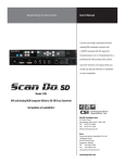
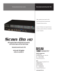
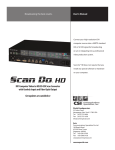
The VGA and Macintosh® Computer to Video Scan Converter (Including Scan Do Pro/C with Component Video Output and Scan Do Pro/D with SDI and Component Output and RS-232 Control) USER’S MANUAL Eighth Edition November, 1999 WORLD HEADQUARTERS 55 Cabot Court Hauppauge, NY 11788 USA TEL: (631) 273-0404 FAX:(631) 273-1638 WWW: http://www.commspecial.com EMAIL: [email protected] Singapore Representative Office 7500A Beach Road #15-314 The Plaza Singapore 199591 TEL: +65 293 0258 FAX: +65 293 1538 EMAIL: [email protected] P/N 101383 Rev B Copyright1999 CONTENTS User & Certification Information _________________________ 2 Introduction __________________________________________ 3 Installation ___________________________________________ 4 Operation ___________________________________________ 6 Genlocking _________________________________________ 10 Tips for Improving Your Converting Computer Images _______ 12 Troubleshooting ______________________________________ 15 Accessories ________________________________________ 16 Rear Connector Pin-outs ______________________________ 17 Statement of Warranty ________________________________ 19 INCLUDED WITH THIS PRODUCT YOU SHOULD HAVE: 1 - Scan Do Pro Computer to Video Scan Converter 1 - Universal input power supply 1 - AC power line cord 1 - 6 foot Computer input cable for VGA and Macintosh 1 - 12 foot composite video output cable 1 - 12 foot S-Video output cable 1 - User’s Manual 1 - Product Registration card If you purchased a Scan Do Pro/D, you will also have: 1 - User's manual for RS-232 Remote Control with software 1 - RS-232 DB-9 M/F cable AVAILABLE OPTIONAL ACCESSORIES: • 12 foot BNC adapter cable for Scan Do Pro’s RGB output • 12 foot Sharp projector cable for Scan Do Pro’s RGB output • 12 foot SCART cable for Scan Do Pro’s RGB output • RF Modulator for North America channels 3 and 4 • AC line cords for North America, Japan, or Europe • Rack mounting kits Scan Do is a trademark of Communications Specialties, Inc. Macintosh and Mac are registered trademarks of Apple Computer, Inc. Scan Do Pro User’s Manual Page 1 USER & CERTIFICATION INFORMATION FCC STATEMENT: WARNING: This equipment generates, uses and can radiate radio frequency energy and, if not installed and used in accordance with the instruction manual, may cause interference to radio communications. It has been tested and found to comply with the limits for a Class A computing device pursuant to Subpart B of Part 15 of FCC Rules, which are designed to provide reasonable protection against such interference when operated in a commercial environment. Operation of this equipment in a residential area is likely to cause interference in which case the user, at his own expense, will be required to take whatever measures may be required to correct the interference. UL INFORMATION: UL INFORMATION This product carries the UL and CUL marks for ITE equipment, Listing #: 8D47 CE INFORMATION: CE INFORMATION Standards to which conformity is declared: EMC EN 55022: 1994, CISPR 22: 1993, Class B Limit EN 50082-1: 1992 IEC 801-2: 1991 IEC 801-3: 1984 IEC 801-4: 1988 POWER SUPPLY INFORMATION: ○ ○ ○ ○ ○ ○ ○ ○ ○ ○ ○ ○ ○ ○ ○ ○ ○ ○ ○ ○ ○ ○ ○ ○ ○ ○ ○ ○ ○ ○ ○ ○ ○ ○ ○ ○ ○ ○ ○ UL INFORMATION: UL INFORMATION This product carries the UL and CUL marks for ITE equipment, Listing #: 2L85 CE INFORMATION: CE INFORMATION Standards to which conformity is declared: EMC EN 55022: 1987, CISPR 22: 1993, Class B Limit EN 50082-1: 1992 IEC 801-2: 1991 IEC 801-3: 1984 IEC 801-4: 1988 Page 2 Scan Do Pro User’s Manual INTRODUCTION T Communications Specialties, Inc. 55 Cabot Court Hauppauge, NY 11788 USA TEL: (631) 273-0404 FAX: (631) 273-1638 WWW: http://www.commspecial.com EMAIL: [email protected] Singapore Representative Office 7500A Beach Road #15-314 The Plaza Singapore 199591 TEL: +65 293 0258 FAX: +65 293 1538 WWW: http://www.commspecial.com EMAIL: [email protected] hank you for purchasing Scan Do Pro. With Scan Do Pro, you now have the ability to convert your high resolution computer video signal into a form suitable for recording on a VCR or displaying on a conventional TV or video monitor. In addition, Scan Do Pro offers genlock with timing, allowing integration of computer graphics into a broadcast or professional environment. Scan Do Pro does not require any special software and operates completely externally from yourcomputer. We advise that you read the section entitled Tips for Improving Your Converted Computer Images later in this manual. It provides some useful suggestions for obtaining the best possible image from your Scan Do Pro. It also explains what you should expect, in terms of image quality, when your computer images are recorded on a VCR or displayed on a conventional video monitor or TV. Like all the products from Communications Specialties, Scan Do Pro comes with our continuing commitment to provide support. In order to assist us in this process, please be sure to mail in your product registration card. This will make it easier for us to notify you with any new product announcements or other information concerning our product line. Should you need to contact us for support, our office is open Monday through Friday, from 8:30 AM to 5:00 PM Eastern Time. We also offer a comprehensive web site for your added convenience. Thank you for choosing Scan Do Pro. As always, we welcome your comments and suggestions. Scan Do Pro User’s Manual Page 3 INSTALLATION INSTALLATION STEPS: AVAILABLE OUTPUTS: 1. Disconnect your monitor from the monitor port on your PC. 2. Connect the 6 foot input cable, provided with Scan Do Pro, from the monitor port on your computer to the connector on the rear panel of Scan Do Pro for either VGA IN or MAC IN. This input cable is used to connect to both Mac and VGA computers. 3. Connect your monitor, if you have one, to the MONITOR connector labeled VGA OUT or MAC OUT. 4. Connect the power supply provided with Scan Do Pro to the connector labeled POWER. Connect the AC line cord to the wall outlet to provide power to Scan Do Pro. 5. Connect one of Scan Do Pro's video outputs to your video equipment. Depending on what type of video equipment you are connecting to, you may use one or more of the following outputs. Composite: This is a single composite video signal and is compatible with the "video" input on VCR's and consumer TV/monitors as well as all professional video equipment. It cannot be connected to the "antenna" input. S-Video: This is an advanced form of video where the brightness and color parts of the image are actually on two separate signals. This signal is sometimes called S-VHS, S-Video or Y/C. It is also compatible with Hi-8 and the Beta-ED standards. Use of this output will yield a better quality picture than the VIDEO output. SYNC TYPES: Red, Green, Blue, Sync: This output has separate RED, GREEN, BLUE, and SYNC signals which can be used by some video projectors and monitors. On Scan Do Pro/C and Pro/D models only: R-Y, Y, B-Y: The component video signals are available on the BNC connectors in lieu of the RED, GREEN, and BLUE signals as determined by the front panel control. On Scan Do Pro/D model only: SDI: The serial digital output provides an SDI output in accordance with SMPTE 259M Page 4 Scan Do Pro User’s Manual VIDEO STANDARD SELECTION: NTSC/PAL: This switch selects the video timing standard to be used for the VIDEO, S-VIDEO, and RGB outputs. NTSC is the standard for the USA, Canada, Mexico, Japan, and parts of South America. PAL is used throughout most of Europe, the Middle East, Southern Asia, and the Pacific Rim. All outputs are available at the same time. Unused outputs do not have to be terminated if they are not being used. The REFERENCE GENLOCK IN and OUT connection are described fully in the genlocking section. Complete the installation by powering ON your computer if it is not already ON. The front panel green indicator labeled INPUT should light after the computer is turned on to indicate it is receiving a proper signal from the computer. Please refer to the OPERATION section for an explanation of this indicator. Be sure the front panel FREEZE light is OFF to see your computer's image on Scan Do Pro's outputs. Scan Do Pro User’s Manual Page 5 OPERATION S can Do Pro not only offers high performance and reliability, but also provides an extremely easy, intuitive user interface. However, in order to fully understand how Scan Do Pro operates and to take advantage of all of its features, we suggest that you read this section in its entirety. If, after becoming familiar with the unit’s operation and features, you still have questions and need to contact us, please refer to Page 3 for our phone, fax, email and web address. DIAGNOSTIC LEDS: Power: This indicator tells when power is present and Scan Do Pro is ON. If this light is glowing dim or not at all, it is an indication that something might be wrong with the internal power supply. Input: This indicator tells when a valid computer signal is present at the VGA In or Mac In connector on the rear panel. VGA AND MAC RESOLUTIONS SUPPORTED: Scan Do Pro will support any resolution having a horizontal sync frequency within the range of 31-71 kHz. Generally, this will include PCs up to 1280 x 1024 at 60 Hz. Interlaced resolutions are not supported. HOW TO ACTIVATE TEST SIGNALS: Test: This button will force Scan Do Pro to generate a test signal on its composite and S-Video outputs. Press the button once and the unit will generate color bars. Press it again to turn off the test signal generator. The green LED on the Test button indicates when the test pattern generator is in operation. COLOR BARS WHEN TEST IS NOT ACTIVATED: From time to time, your Scan Do Pro may output color bars even though you have not pushed the Test key on the front panel. If your unit is generating color bars but the LED on the Test key is not illuminated, there is either no input signal from the computer or the input signal from the computer is not in a resolution or mode supported by Scan Do Select. Page 6 Scan Do Pro User’s Manual SHRINKING THE IMAGE TO FIT ON THE SCREEN: Underscan: Because most TV monitors "overscan" their image display, some desirable part of the image may be lost. The UNDERSCAN button can be used to shrink the image, both horizontally and vertically, approximately 10% in size. Push the button to shrink the image and the green light will illuminate. Push it again to restore the image to its original size and the light will extinguish. REDUCING FLICKER IN THE IMAGE: Anti-Flicker: This button will activate one of two levels of flicker reduction. When the filter is not activated, the LED on this button remains unlit. Pressing the button once activates level one of the anti-flicker filter and illuminates the LED.Using Level 1, you will still see some flicker but will benefit from a greater amount of vertical detail compared to Level 2. We recommend using Level 1 unless you find the amount of remaining flicker annoying. Pressing the button again activates Level 2 of the anti-flicker filter. (The LED remains lit.) Level 2 eliminates all flicker, but also reduces the level of detail in the image. Pressing the button once again will turn off the anti-flicker filter and extinguish the green LED. Do not assume that one setting will always provide you with most desirable image. Depending on the types of images you are viewing, you will find different settings will provide the best result. IMAGE FREEZE: Freeze: You may desire to freeze or stop the image on your video screen without stopping your computer application. If the button is pressed, the image is frozen on Scan Do Pro's video outputs. The green light will also illuminate. Press the button again to extinguish the light and resume normal operation. While in the freeze mode, all keypad functions are disabled except the FREEZE key. If you attempt to press any other key while in the freeze mode, the indicator light on the freeze key will flash to indicate Scan Do Pro is in the freeze mode. Scan Do Pro User’s Manual Page 7 ACTIVATING THE COMPONENT OUTPUT: Y R-Y B-Y: This button is only active on Scan Do Pro/C and Scan Do Pro/D models, including Scan Do Pro units that have been upgraded to feature component output. The component output supports the signal level differences for both Betacam® and MII component video formats. When you first push the Y R-Y B-Y button and the light first activates, the signal levels on the component output are in the Betacam mode. When you press the Y RY B-Y button a second time, the signal levels on the component output will go to the MII mode. Push the button again and the outputs will return to Red, Green, and Blue and the light will go out. If the light flashes and then goes out when the button is pressed, then the Y R-Y B-Y component output option is not installed. POSITIONING THE IMAGE ON THE SCREEN: Image Positioning Arrows: TV monitors and video projectors may not always display the image in the center of the screen even when it is underscanned. Scan Do Pro has four buttons that allow you to position the displayed image up, down, left, and right to properly position the image in the center of the screen. These positioning controls will move one increment for every push of the button. If you leave the button pressed it will move continuously, slow at first, then fast. These positioning buttons are only active as positioning controls when Scan Do Pro is not in the GENLOCK PHASING mode. MAGNIFYING THE IMAGE: Magnify: Pushing this button will magnify the image from your computer by approximately 160%. When you first press the button, the green indicator will light and the output of Scan Do Pro will show the center portion of the computer image, full screen on its outputs. By using the four positioning buttons you can show any magnified portion of the original computer image. If you press HOME on the UNDERSCAN button, the image will reposition first to the upper left corner, then to the lower left when pressed again, then lower right, then the upper right as the button is pressed in succession. To restore the image to its original size, press the MAGNIFY button again. Page 8 Scan Do Pro User’s Manual OTHER OPERATIONAL FEATURES: Blue Screen: From time to time you will notice the video outputs will show a blue screen. Sometimes this happens for a brief instant, and other times the blue screen output is continuous. Scan Do Pro automatically produces this blue screen under any one of the following conditions: • There is no input signal from the computer • There is a signal from the computer, but it is not in a resolution or mode supported by Scan Do Pro • Your computer has temporarily changed resolutions during a program and the output of Scan Do Pro has momentarily flashed a blue screen If you think the blue screen should not occur, make sure one of the above conditions is not occurring. Computer Display Resolution Support: The design of Scan Do Pro does its best to determine the pixel resolution (i.e. 640 x 480) and the vertical refresh rate (i.e. 72 Hz) that is coming from your computer. While there are published standards for most of the display modes, some manufacturers of older cards may have chosen to vary slightly from these standards. If you encounter a display mode that matches one of the modes listed on page 6, but Scan Do Pro does not respond to it, we want to know about it. Give us a call or drop us a note and tell us the computer make and model, make and model of the video display card, and the display resolution and vertical refresh rate you're having a problem with. We'll do our best to replicate the problem and let you know what we can do to fix it. The Computer Input Cable: The cable supplied with Scan Do Pro for connecting to your computer is somewhat different than what you might be used to seeing. It is designed to be compatible with both VGA and Macintosh computers. It is specially wired and DB-15 to HD-15 adapters cannot be used as substitutes. When connecting Scan Do Pro to your computer, start with your computer output to match the right connector on the cable. Scan Do Pro User’s Manual Page 9 GENLOCKING The information in this section need only be reviewed if you intend to genlock Scan Do Pro. Genlocking is the process whereby the video output of Scan Do Pro is synchronized or "locked" to a reference video signal. This is sometimes done when the Scan Do Pro video outputs are to be mixed with other video signals to create one video signal. If you intend to only display the Scan Do Pro video output directly onto a video projector or monitor, or record it onto a video tape by itself, then genlocking is not required. The genlock connections to Scan Do Pro are used only for synchronization. Scan Do Pro does not "overlay" the computer image on top of the genlock video signal. GENLOCK REFERENCE CONNECTION: In: This connector is the input for the reference video signal for genlocking Scan Do Pro. It will accept any composite video signal (including "black burst") in the video standard selected by the NTSC/PAL switch. It is important that the genlock reference input be a stable or time base corrected video signal. Never use a video signal from a VCR tape playing back, unless it is going through a time base corrector to stabilize it. Out: This connector is the passive loop-through of the genlock reference input signal. This connector should be terminated in 75 ohms when an input reference signal is present. This can be done either by placing a termination on the connector or by downstream equipment. Once the reference genlock input is connected to Scan Do Pro, it is necessary to phase both the horizontal and subcarrier phasing of Scan Do Pro's video outputs to the genlock reference signal. Page 10 Scan Do Pro User’s Manual GENLOCK SET-UP PROCEDURE: First, push the GENLOCK button on the front panel. The green light will indicate that a valid reference video signal is present. Next, push the GENLOCK PHASING button on the front panel. The four arrow buttons on the front panel now are used for subcarrier (SC+, SC-) phasing and horizontal (H+, H-) timing. To set the horizontal timing of Scan Do Pro relative to the reference input, display both the reference input and Scan Do Pro's video simultaneously on a waveform monitor. The waveform monitor should be synchronized to the reference input. Adjust H+ or H- on Scan Do Pro to align the leading edge of horizontal sync of Scan Do Pro with that of the reference input. To set the subcarrier phasing of Scan Do Pro relative to the reference input, display both the reference input and Scan Do Pro's video simultaneously on a vectorscope display. The vectorscope should use the subcarrier of the reference to synchronize the vectorscope. Adjust SC+ or SC- on Scan Do Pro to align the burst of Scan Do Pro with that of the reference input. After timing and phasing is accomplished, push the GENLOCK PHASING button again to extinguish the green light and to save the settings in non-volatile memory. Make sure the green light is lit on the GENLOCK button to keep Scan Do Pro in the genlock mode. You may "free run" Scan Do Pro at any time by pushing the GENLOCK button to extinguish the green light on the GENLOCK button. You can then reinstate genlocking by pushing the GENLOCK button. If the GENLOCK button is pushed and there is no reference genlock signal present, the GENLOCK light will flash on and off. If you then connect a valid reference input, the GENLOCK light will stay on steady. You can also push the GENLOCK button again to extinguish the light. If Scan Do Pro goes out of the genlock mode for any reason, or if power is lost, Scan Do Pro will remember the last genlock timing and phasing settings. Scan Do Pro User’s Manual Page 11 TIPS FOR IMPROVING YOUR CONVERTED COMPUTER IMAGES I t has been our experience, at CSI, that customers are sometimes surprised that computer images converted to video do not look as sharp and vivid as the original computer image does. Unfortunately, this result is inevitable regardless of the scan converter you use, for the technology behind TV video is far inferior to that behind newer computer video standards. This is not to say that the quality of scan converter you use doesn’t matter, but even the very best scan converter will not provide output that matches the quality of your original computer picture. Scan converters, like Scan Do Pro, were created to bridge the differences between the relatively new standards of computer video and the 40-year old standards of conventional TV video. When using a scan converter, there are several things you can do to get the best possible results from the conversion process. These involve understanding the limitations of standard TV video and creating images that “work around” these shortcomings. The following tips apply whether you are displaying your scan converter output directly on a monitor or recording it onto videotape. While you should have realistic expectations regarding the type of image you will be able to obtain, taking the following steps will definitely improve your results: KNOW WHAT YOUR CONVERTED IMAGE WILL LOOK LIKE: First of all, when creating any computer presentation that you ultimately plan to display in video format, it is always a good idea to hook up a Scan Do Pro and view the output on a TV monitor during the creation process. While this may require a little bit of extra set-up time, it has the potential to save you far more time and aggrevation later on by avoiding the need to correct any unwanted “surprises” in your finished work. USE BLACK AND WHITE: In the world of standard TV video, shades of gray are processed differently than colors. In fact, TVs and VCRs process black, white and all grays in between with a minimum of distortion. Use this to your advantage in the design process by substituting gray in place of color whenever appropriate. AVOID INTENSE COLORS: Along the same lines, fully saturated colors (like bright red and green) look terrible on a TV monitor. And, recording these colors to videotape makes them look even worse. Whenever possible, try to use slightly muted colors instead. Page 12 Scan Do Pro User’s Manual USE HIGH GRADE VIDEO TAPE: When making a VCR recording, use a name brand videotape with a “Pro” or “Broadcast” grade. An S-VHS tape can also be used, even if you’re only making a standard VHS recording. Also, record using the fastest possible speed (shortest time mode). You will have less noise and tape jitter in your recording. PAY ATTENTION TO YOUR BORDERS: TV and video signals are designed to bleed off the edges of the screen. This means that when a computer picture is converted to a TV standard, the borders of your picture will be lost. In order to avoid this cropping effect, you can use theZoom feature on Scan Do Pro to display your image at 85%. If you would prefer to use the bleeding effect in your final display, be sure to design your presentation with ample borders surrounding the “live area” of your image. That way, when the cropping does occur, no critical part of your picture will be lost. ELIMINATE FLICKER: By far, the most annoying effect that occurs when a computer image is converted to video is “flicker.” This rapid flashing may appear throughout the screen or localized in one particular area, and is due to the fact the TV monitors, unlike computer monitors, draw the even and odd lines within the picture in alternating passes. This effect is most noticeable on thin horizontal lines – particularly, bright lines against a dark background. Scan Do Pro offers a two-step anti-flicker filter that provides you with the choice of how much flicker should be eliminated. (As more flicker is eliminated, there is an inherent trade-off of loss of vertical detail.) When using this feature, experiment with different settings, as you will receive the maximum benefit from different levels depending on the type of visual you are displaying. You may also want to keep in mind when designing your presentation that the less thin, horizontal lines you use in your image, the less likely that any flicker will be visible. USE S-VIDEO: Almost all new, larger screen commercial TVs have an S-Video jack. S-Video is a superior form of the standard TV video signal, in that the brightness and color components of the image are separated into two separate signals. This results in far fewer distortions and noticeably superior image quality. So, if your TV or VCR is S-Video equipped, definitely use the S-Video output from Scan Do Pro. You’ll see a difference. Scan Do Pro User’s Manual Page 13 Page 14 Scan Do Pro User’s Manual TROUBLESHOOTING IF THIS IS YOUR PROBLEM: Then Check The Following: NOTHING WORKS OR THERE IS NO VIDEO OUTPUT: • Is the green POWER LED lit? If it is not, check to make sure that the external AC power supply is plugged into both the Scan Do Pro unit and the AC wall outlet. • Check to make sure that the computer is properly sending out a VGA or Mac signal by plugging the monitor directly into the computer’s video output. • Is the green Input LED lit? If it is not, check that your computer is correctly connected to the Input connector on Scan Do Select. If it is connected properly, then your computer may not be producing a resolution within the valid range (see page 6) or may not be producing any signal at all. • Press the Test button to see if you get color bars on the composite and S-Video outputs. If you do get color bars, then the problem is related to your input signal. Check the items mentioned in the above bullet. If you do not get color bars, the problem is related to your output. Is the VCR or video monitor in the proper mode to accept direct video input? Is the output cable connected properly? • When using a laptop, try turning off the laptop’s LCD screen and having the VGA signal output through the external port only. SOME OF THE IMAGE IS BEING LOST OFF THE SIDES, TOP OR BOTTOM: • This is normal if you are in the overscan mode. See page 6 for instructions on how to use the underscan key. Then use the cursor keys to center your image on the screen. THE COLOR ON THE TV MONITOR IS DIFFERENT THAN THE COLOR ON THE COMPUTER MONITOR: • The colors on your TV monitor will never exactly match the colors on your computer monitor because each of these devices reproduce color differently. However, try adjusting the color, tint, contrast and brightness controls on your TV to help match the colors as best you can. The color bar test pattern built into Scan Do Select may help you in this process. NO VIDEO ON OUTPUTS (JUST A COLOR BAR TEST PATTERN): Scan Do Pro User’s Manual Page 15 ACCESSORIES The following accessories are available for Scan Do Pro. They may be ordered from your dealer or directly from Communications Specialties, Inc. If you need an accessory that you don't see here or have a specific application for which you need assistance, please give us a call. Page 16 ITEM # 1278 DESCRIPTION Upgrade for RS-232 Remote Control. This will upgrade a Scan Do Pro to a Scan Do Pro w/RS-232. This upgrade can be done by the user or the Scan Do Pro can be returned to Communications Specialties and we will perform the upgrade. 1279 Upgrade for Y, R-Y, B-Y component output. This will upgrade a Scan Do Pro to a Scan Do Pro/C. This upgrade can be done by the user or the Scan Do Pro can be returned to Communications Specialties and we will perform the upgrade. 1280 Upgrade for serial digital (sdi) output, component output and RS-232 Remote Control. This upgrade can be done by the user or the Scan Do Pro can be returned to Communications Specialties and we will peform the upgrade. 1246 Single rackmount kit. This kit allows one Scan Do Pro to be rackmounted. 1247 Double rackmount kit. This kit allows two Scan Do Pro's to be rackmounted. 1152 RGBS cable for BNC connection. A 12 foot cable that connects the RGBS output of Scan Do Pro to video equipment with BNC connectors. 1153 RGBS cable for Sharp LCD projectors. A 12 foot cable that connects the RGBS output of Scan Do Pro to the DB-15 connector on Sharp LCD projectors. 1155 RGBS cable for SCART connector on European TV monitors. A 4 meter cable that connects the RGBS output of Scan Do Pro to a SCART A/V connector. 1156 RGBS input cable. A 3 foot cable that connects an RGBS signal to the input of Scan Do Pro. Scan Do Pro User’s Manual REAR CONNECTOR PIN-OUTS POWER Center Outer +5 Vdc In Ground VGA Out/MAC In (HD-15 Connector) PIN 1 2 3 4 5 6 7 8 9 10 11 12 13 14 15 VGA OUT Red Green Blue ID bit 2 Ground Red Ground Green Ground Blue Ground N/C Monitor Present Ground (ID bit 0) ID bit 1 H-Sync Out V-Sync Out ID bit 3 1 2 3 4 5 6 7 8 9 10 11 12 13 14 15 VGA IN Ground Red Reserved ID bit 0 Green Red Ground ID bit 1 N/C Blue ID bit 2 Ground V-Sync In Computer Present Ground H-Sync In COMPOSITE VIDEO OUTPUT Center Outer Video Out Video Ground S-VIDEO OUTPUT 1 2 Ground Ground RGB OUTPUT Center Outer Video Out Video Ground VGA In/MAC Out (DB-15 Connector) Scan Do Pro User’s Manual MAC IN Red Green Blue ID bit-2 Ground Red Ground Green Ground Blue Ground N/C Computer Present Ground (ID bit 0) ID bit 1 H-Sync In V-Sync In Comp. Sync In MAC OUT Ground Red Comp. Sync Out ID bit 0 Green Red Ground ID bit 1 N/C Blue ID bit 2 Ground V-Sync Out Monitor Present Ground H-Sync Out 3 Luminance 4 Chrominance Page 17 Page 18 Scan Do Pro User’s Manual WARRANTY C ommunications Specialties, Inc. (CSI) warrants that for a period of three years after purchase by the Buyer, Scan Do Pro will be free from defects in material and workmanship under normal use and service. A Return Material Authorization (RMA) number must be obtained from CSI before any equipment is returned by the Buyer. All material must be shipped to CSI at the expense and risk of the Buyer. CSI's obligation under this warranty will be limited, at its option, to either the repair or replacement of defective units, including free materials and labor. In no event shall CSI be responsible for any incidental or consequential damages or loss of profits or goodwill. CSI shall not be obligated to replace or repair equipment that has been damaged by fire, war, acts of God, or similar causes, or equipment that has been serviced by unauthorized personnel, altered, improperly installed, or abused. RMA numbers and repairs can be obtained from: Communications Specialties, Inc. 55 Cabot Court Hauppauge, NY 11788 USA TEL: (631) 273-0404 FAX: (631) 273-1638 or, in the Asia Pacific Region: Singapore Representative Office TEL: +65 293 0258 FAX: +65 293 1538 (See page 3 of this manual for complete address) RMA numbers can also be obtained from our web site: http://www.commspecial.com Please have your serial number (located underneath your unit) available when contacting us. Scan Do Pro User’s Manual Page 19 Page 20 Scan Do Pro User’s Manual