1
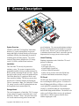
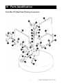
Carbo-Max 750 HF
User Manual
wwww.chartbeverage.com
b
Copyright: Chart Industries, Inc., Jan. 2003
Table of Contents
I
Safety . . . . . . . . . . . . . . . . . . . . . . . . . . . . . . . . . . . . . . . . . . . . . . . . . . . . . . 1
Warnings
First Aid and Emergency Action
Further Information Sources
II
General Description . . . . . . . . . . . . . . . . . . . . . . . . . . . . . . . . . . . . . . . . . . 2
System Overview
Installation
Storage vessel
Vessel Plumbing
Fill Circuit
Pressure Control Circuit
Gas Use Circuit
Safety Vent Circuit
Pressure and Contents Gauges
CO2 Fill Box
Fill Hose and Vent Line
Your Bulk CO2 Supplier
III
Parts Identification . . . . . . . . . . . . . . . . . . . . . . . . . . . . . . . . . . . . . . . . . . . 5
MVE Carbo-Max 750
Installation Components
IV
Vessel Specifications . . . . . . . . . . . . . . . . . . . . . . . . . . . . . . . . . . . . . . . . . 8
Dimensions
Rates and Pressures
Design Criteria
V
Operation And Troubleshooting . . . . . . . . . . . . . . . . . . . . . . . . . . . . . . . . 9
Facts to Know
General Operating Instructions
Troubleshooting Guide - CO2 Vessel
Troubleshooting Guide - Fill Box
VI
Ordering Service And Parts . . . . . . . . . . . . . . . . . . . . . . . . . . . . . . . . . . . 14
Service and Maintenance
Ordering Parts or Service
Important Telephone Numbers
VII
Warranty . . . . . . . . . . . . . . . . . . . . . . . . . . . . . . . . . . . . . . . . . . . . . . . . . . . 15
Warranty Policy
Warranty Claims Procedure
VIII System Flow Schematic . . . . . . . . . . . . . . . . . . . . . . . . . . . . . . . . . . . . . . 16
Copyright: Chart Industries, Inc., Jan. 2003
c
I Safety
to work with CO2 and the bulk liquid CO2
pressure vessels. They should be familiar with all
pertinent safety procedures.
IMPORTANT SAFETY PRECAUTIONS
The type of vessel described in this manual
holds and dispenses carbon dioxide (CO2)
gas under pressure. All persons using this
equipment must read and understand the
operation and safety information contained in
this manual.
FIRST AID AND EMERGENCY ACTION
If inhaled:
• Move to fresh air immediately.
• If not breathing, give artificial respiration.
• If breathing is difficult, give oxygen.
• Get immediate medical attention.
WARNINGS
CO2 gas is a colorless, odorless, tasteless gas
that displaces oxygen and will not support life.
It is difficult to detect without special equipment.
Avoid breathing or contacting CO2 in gas, liquid
or solid form. Exposure to concentrations of
less than 5% for less than 15 minutes can cause
physical symptoms including unconsciousness,
injuries or death. Even low concentrations of
CO2 can cause:
In case of frostbite:
• End exposure immediately.
• Do not rub or pour water on the affected area.
• Get immediate medical attention.
Rescue:
• Do not attempt a rescue in areas of high CO2
concentrations without proper life-support or
rescue equipment.
(Avoid being the next victim.)
• Thoroughly ventilate areas of possible high
CO2 concentration before entering them.
• Dizziness, headaches, nausea or disorientation
• Increased respiration or heart rate
• Shortness of breath or rapid suffocation.
CO2 is heavier than air and can collect in low areas
such as basements, stairwells, and confined spaces.
Avoid entry into areas where CO2 leaks or high
concentrations of CO2 are suspected. Enter those
areas with caution only after they have been
thoroughly ventilated.
In case of spills or leaks:
• Evacuate all personnel immediately from
affected areas.
• Thoroughly ventilate the area of the spill or
leak before entering.
• CO2 is heavier than air. It displaces oxygen and
will collect in low or confined areas.
Whenever the vessel is inside a building it’s safety
relief circuit must be connected to an outdoor vent
typically in the fill box. The fill box and/or vent
must never be located in or above any belowground spaces or stairwells. The vessel must not
block emergency exits, aisles, fire suppression
equipment or utility boxes or accesses. CO2 lines
or hoses must be located away from traffic areas
and heat sources and must be protected from
potential causes of damage. All connections, lines,
and components must be leak-free .
FOR MORE INFORMATION CONTACT:
Local CO2 supplier
or
Compressed Gas Association
725 Jefferson Davis Highway, Suite 1004
Arlington, VA 22202-4100 USA
Telephone: (703) 412-0900
FAX: (703) 412-0900
This equipment should be installed and serviced
only by professional personnel who are qualified
1
Copyright: Chart Industries, Inc., Jan. 2003
II General Description
UID E
LIQ DIOXID
BON
CAR
special insulation. The vacuum and insulation minimize
the entry of unwanted heat into the liquid CO2 stored in
the inner vessel. When CO2 gas is needed, liquid CO2
is withdrawn from the inner vessel, converted to gas and
dispensed to the beverage system or other use point.
System Overview
The MVE Carbo-Max 750 ‘High Flow’ bulk carbon
dioxide (CO2) system is designed for low pressure
storage and supply of carbon dioxide gas for beverage
carbonation, brewing, beer dispensing, ph control in
swimming pools, and other purposes. The system
consists of three primary elements: the CO2 storage
vessel, CO2 fill box, and the fill and vent hoses.
Vessel Plumbing
Plumbing components on the Carbo-Max 750 vessel
perform six functions:
Installation
•
•
•
•
•
•
The Carbo-Max 750 can only be operated as a
stationary system. The system is comprised of the
permanently installed vessel, an outdoor-mounted CO2
fill box, and the connecting fill and vent hoses. The fill
hose and vent line join the vessel to the outdoor fill box.
The fill box allows the CO2 supplier to fill the vessel
from outside the building. The delivery process takes
only about 10-15 minutes and does not interrupt the
CO2 user’s operations. Note: The Carbo-Max 750 bulk
CO2 storage vessel is not DOT regulated and must not
be transported when it contains liquid CO2.
Fill Circuit
The fill circuit allows liquid CO2 to be transferred into
the vessel during the delivery process. It consists of a
brass fill fitting in the fill box, a fill hose, a valve on the
vessel, and MVE’s patented Sure-Fill assembly.
Liquid CO2 is transferred into the vessel through the
brass fill box fitting and the fill hose. The shut-off valve
on the vessel’s fill port allows service to be performed
on the fill-box / fill-line segment of the fill circuit
without emptying the vessel.
Storage Vessel
The vessel component in a Carbo-Max 750 CO2 storage
system consists of an inner vessel and an outer vessel,
much like a ThermosTM bottle. The space between the
two vessels contains a nearly perfect vacuum and a
Copyright: Chart Industries, Inc., Jan. 2003
Liquid CO2 fill
Gas supply (Gas Use)
Liquid supply (Liquid Use)
Pressure control (Economizer)
Safety vent or pressure relief (Sure-Fill & Vent)
Pressure and contents measurement (Gauges)
2
The vessel’s Sure-Fill assembly enables fast, troublefree filling without having to manually vent excess
pressure that might develop during a CO2 delivery.
The Sure-Fill automatically maintains the optimum
internal vessel pressure during the fill process by
venting excess pressure outdoors through the safety
vent and fill box. This vent process stops when the
vessel is full.
Fill Circuit
Sure-FillTM Circuit
Economizer Circuit
Vent Circuit
Gas Delivery
Circuit
Liquid CO2
Dispense Port
1/2
E
Gas Use Circuit
Carbon dioxide gas is supplied to the use point through
the gas use circuit. The Carbo-Max 750 withdraws
liquid CO2 from the bottom of the inner vessel through a
vaporizer coil where it converts to gas for final line use.
F
LIQUID
GAS
The conversion from liquid to gas occurs when liquid
CO2 flows through a stainless steel vaporizer/gas use
coil located between the inner and outer vessel walls.
As it is needed, carbon dioxide gas is produced by the
vaporizer coil. Then it passes through the isolation valve
and final line regulator to the point of use.
The final line regulator controls gas flow to the use-point.
The factory setting on the final line regulator is 90 psi
but the pressure may be adjusted to the needs of the
application. The regulator setting for soft drinks is
commonly between 90 and 115 psi. Secondary pressure
regulators may be added ‘downstream’ for applications
such as bag-in-the-box, beer, or diet systems.
Consult with the use-point equipment manufacturer for
the proper regulator and pressure setting.
Liquid Supply Port
The Carbo-Max 750 is equipped with an alternative
liquid CO2 supply port. This port should be used only
for high demand applications that require CO2 to be
dispensed in liquid form. The vessel’s gas supply and
liquid supply ports may be used simultaneously for
separate applications.
Pressure Control Circuit
The pressure control circuit (also called the
economizer circuit) assists in regulating the
operating pressure of the vessel. It maintains the
correct operating pressure while it conserves gas
for efficient system performance.
Vaporizer Coil
6” (15.2 cm) Uni-body Legs
Sufficient internal vessel pressure is needed for
supplying CO2 gas and for preventing the stored liquid
3
Copyright: Chart Industries, Inc., Jan. 2003
point to fill the storage vessel and to vent excess
vessel pressure out of the building. The fill box
has a brass fill fitting, a connection for the safety
relief vent circuit, a connection point for a safety
clip, and a lockable door. Two standard types of
fill boxes are available; a surface-mount model
and a flush-mount model. Fill boxes must be
mounted outside the building where they are easily
accessible to the CO2 supplier and where they can
safely disperse excess CO2 pressure outdoors.
carbon dioxide from changing to ‘dry ice,’ the solid
form of CO2. However, internal pressure that is too high
can cause venting and difficulties refilling the vessel.
The “economizing” process is controlled by a regulator
that monitors the vessel’s internal pressure. When the
vessel pressure exceeds the set point of the regulator
(factory set at 140 psi), the regulator opens allowing
CO2 gas to flow directly into the gas use circuit whenever
CO2 gas is being used. By taking gas from the top of the
vessel instead of liquid CO2 from the bottom, the internal
pressure of the tank is reduced and controlled.
Fill Hose And Vent Line
The third major element of a stationary bulk CO2
system is comprised of a fill hose and vent line.
These two lines join the CO2 storage vessel with
the outdoor fill box.
Safety Vent Circuit
The inner pressure vessel of this storage system is
designed to meet or exceed the ASME Section VIII,
Division 1 pressure vessel code. The code dictates
that the vessel be protected against excess pressure
by a safety relief valve. Chart uses two safety relief
valves for added safety; an ASME relief valve set at
300 psig and an additional relief valve set at 450 psig.
The relief valves must always be vented outdoors by
a vent tube, usually through the fill box, to prevent
potential concentration of CO2 within the building.
The 300 psig relief valve may open during CO2
deliveries or when CO2 is not being used regularly.
The fill hose is a pressure rated line that connects
the brass fill fitting in the fill box to the fill
circuit on the vessel. It is constructed with FDA
compliant materials,
The vent line is as important as any component
in the system. It connects the safety relief valves
on the vessel to either the outdoor fill box or to an
alternative outdoor vent tube.
NOTE: The Carbo-Max 750 must always be
connected to an outdoor vent line when it contains
CO2 and is indoors.
Pressure And Contents Gauges
A contents and pressure gauge indicate the status
of the CO2 inside the vessel. The vessel pressure
gauge measures the pressure in the top space of
the inner vessel. This pressure can normally range
between 125 psig and 300 psig but the typical vessel
operating pressure is 125 to 150 psig.
The Bulk CO2 Supplier
The bulk CO2 supplier is also an important part of
the system. Most CO2 suppliers not only provide
timely delivery of CO2 but also install and service
the system. For service, parts, information,
emergency CO2 delivery, or other CO2 related
assistance, contact the local Chart authorized
CO2 supplier. A place has been designated on
page 14 of this manual to record the name and
phone number of the CO2 supplier and other
important service contacts.
The vessel contents gauge measures the approximate
level of CO2 liquid in the vessel. The movement of a
magnetic rod “floating” in the liquid CO2 causes the
needle on the contents gauge to move as the level of
liquid CO2 in the vessel changes.
NOTE: Because the float-rod does not actually float
on the surface of the liquid CO2 it does not provide a
precise measurement of liquid CO2 level.
CO2 Fill Box
The stainless steel CO2 fill box is the second major
element of the Carbo-Max 750 CO2 storage system.
The purpose of the fill box is to provide a convenient
Copyright: Chart Industries, Inc., Jan. 2003
4
III Parts Identification
Carbo-Max 750 (High Flow) Plumbing Components
51
22
21
80
33c
83
20
61
43
19
33d
18
48
51
48
17
45
46
57
42
44
52
32
60
31
52
33b
47
30
79
25
49
39
60
40
33a
34
41
35
5
Copyright: Chart Industries, Inc., Jan. 2003
III Parts Identification Continued
Carbo-Max 750 (High Flow) Plumbing Components
ITEM
17
18
19
20
21
22
25
30
31
32
33a
33b
33c
33d
34
35
39
40
41
42
43
44
45
46
47
48
49
51
52
57
60
61
79
80
83
94
95
-
PART NO.
9094119
5411622
5411029
2300244
5411612
10601088
10591369
1212962
11082128
11708451
11708400
1716162
1716162
1716162
1716162
1717579
1211102
1812289
1213092
2015179
1210622
2111312
11673631
11762975
11762983
1210482
11708442
11044869
6910623
1611592
1110112
1013042
5503831
11720484
10654315
1812279
3911217
3911016
11789983
3836609
10784072
11784496
10591140
DESCRIPTION
QTY
FUNCTION
Float Rod Assembly with Magnet
1 Indicates liquid CO2 level in the vessel
Spring Retainer
1 Secures spring to float rod for adjustment
Extension Spring
1 Provides tension on float rod
O-Ring, Liquid Level Gauge
1 Seals brass plug to vessel
Plug, Brass, Liquid Level Gauge (3/4”-16)
1 Secures the contents gauge to the vessel
Liquid Level Gauge Assembly
1 Includes items 17, 18, 19, and 21
Gauge, Liquid Level / Contents (Roto-Cal)
1 Indicates approximate liquid CO2 contents
Brass Plug (1/8” MPT) (not pictured)
1 Seals unused port on Economizer regulator
Ball Valve (3/8” FPT)
1 Isolates CO2 fill hose from vessel.
Relief Valve, 450 psig (1/2” MPT)
1 Secondary inner vessel safety relief valve
Relief Valve, 300 psig (1/2” MPT)
1 Primary inner vessel safety relief valve
Ball Valve (1/4” MPT x 1/4” FPT)
1 Isolates liquid-side of Economizer regulator
Ball Valve (1/4” MPT x 1/4” FPT)
1 Isolates gas-side of Economizer regulator
Ball Valve (1/4” MPT x 1/4” FPT)
1 On / off control for gas supply
Ball Valve (1/4” MPT x 1/4” FPT)
1 Opens / closes sure-Fill circuit
Ball Valve, Brass (1/4” NPT)
1 On / off control for liquid CO2 supply
Plug, Brass (1/4” MPT)
1 Seals liquid CO2 port when not in use
Regulator, Economizer, 140 psi (1/4” FPT)
1 Controls vessel pressure
Tee, Brass (1/4” FPT x 1/4” FPT x 1/4” MPT) 1 Joins Economizer circuit components
Pressure Gauge, 0-400 psi (1/4” MPT CBM)
1 Displays internal vessel pressure
Tee, Brass (1/4” FPT)
1 Connects gas use and economizer circuits
Regulator, Final Line, 90 psi (1/4” FPT)
1 Controls CO2 gas pressure to use-point
Pressure Gauge, 0-160 psi (1/8” MPT CBM)
1 Indicates CO2 gas pressure to use-point
Tube Stub, Brass (1/4” MPT x 1/2” ODT)
1 Gas use line plumbing extension
Connector, Brass (1/4” x 1/2” ODT)
1 Connects final line regulator to gas use circuit
Elbow, Street, Brass 90D (3/8” MPT)
1 Connects 450 psi relief valve to vent circuit
Tee, Brass Run, (1/2” ODT x 3/8” MPT)
2 Joins vent circuit components
Branch Tee, (1/2” FPT)
1 Manifolds primary & secondary relief valves
Tube, Soft Copper Type L (½” OD, Nominal .375”) ft Joins vent circuit components
Adapter, Pipe-Away (3/8” FPT)
2 Joins 450 & 350 psig relief valves to vent fittings
Connector (5/8” ODT x 3/8” MPT- 45o Flare)
1 Connects CO2 fill hose to vessel
Elbow, Brass 90D (5/16” ODT x 1/4” MPT)
2 Joins Economizer line and circuit components
Tubing, Stainless (5/16” OD)
1 Economizer line
Sure-Fill™ Tube Assembly (3/4”-16)
1 Controls CO2 filling and pressure venting
Elbow, Brass, 90D (1/2” ODT x1/4” MPT)
1 Joins Sure-Fill assembly to vent circuit
Regulator, Sure-Fill, 200 psi (1/4” FPT)
1 Vents excess pressure during CO2 filling
Cap, Plastic, Black
1 Covers vacuum pump-out port
Cap, Plastic, Blue
1 Covers vacuum regeneration port
Label, Carbo-Max 750 High Flow
1
Denotes vessel model
1
Describes vessel safety and operations
Label, CO2 Operations
Label, Chart Industries, Inc.
1
Identifies vessel manufacturer
Label Only, Caution Carbon Dioxide
1
Included in label kits
1
Identifies vessel’s contents
CO2 Regulation Label UN 2187
Copyright: Chart Industries, Inc., Jan. 2003
6
III Parts Identification Continued
Stationary Installation Components
Surface-Mount Fill Box
Part No. 9722279
Flush-Mount Fill Box
Part No. 9723139
5
1
4
2
6
2
ITEM PART NO.
3
1
DESCRIPTION
QTY.
FUNCTION
1
11381021
CO2 Fill Fitting, Brass
1
Connection for CO2 delivery vessel hose
2
3
4
5
6
7
4310689
4310959
2914071
11386771
9111289
10503517
1111182
Lock Assembly (includes key)
Key for Lock Assembly (not pictured)
Locknut SS w/nyl Insert
Surface-Mount CO2 Fill Box (without fittings)
Flush-Mount CO2 Fill Box (without fittings)
Flush-Mount Fill Box Plate
Connector (3/4” MPT x 5/8” - 450 Flare)
1
4
1
1
1
1
Locks fill box door
Replacement key for fill box
Attach fill fitting to fill box studs
Allows outdoor filling and venting of vessel
Allows outdoor filling and venting of vessel
Holds brass fill fitting
Connects fill hose to fill fitting
8
10802912
CO2 Fill Hose only, 5 ft. (2000 psi & FDA)
1
Transfers liquid CO2 from fill box into vessel
8
8
8
8
8
9
10802921
10802947
10802939
10370710
10370728
2811726
CO2 Fill Hose only, 10 ft. (2000 psi & FDA)
CO2 Fill Hose only, 15 ft. (2000 psi & FDA)
CO2 Fill Hose only, 25 ft. (2000 psi & FDA)
CO2 Fill Hose only, 30 ft. (2000 psi & FDA)
CO2 Fill Hose only, 50 ft. (2000 psi & FDA)
Vent Hose (lengths match fill hose)
1
1
1
1
1
1
Transfers liquid CO2 from fill box into vessel
Transfers liquid CO2 from fill box into vessel
Transfers liquid CO2 from fill box into vessel
Transfers liquid CO2 from fill box into vessel
Transfers liquid CO2 from fill box into vessel
Vents excess vessel pressure outdoors
Fill and Vent Hose Kits
PART NO.
10973252
10973308
10973324
DESCRIPTION
5 ft Fill & Vent Hose
10 ft Fill & Vent Hose
15 ft Fill & Vent Hose
PART NO.
10973332
10973341
10973359
7
DESCRIPTION
25 ft Fill & Vent Hose
30 ft Fill & Vent Hose
50 ft Fill & Vent Hose
Copyright: Chart Industries, Inc., Jan. 2003
IV Vessel Specifications
Carbo-Max 750 HF
Dimensions
Diameter
26 in (66 cm)
Height w/o legs (w/legs, add 5 1/2 inches)
68 in (173 cm)
Empty Weight
430 lb (195 kg)
Full Weight
1201 lb (545 kg)
Net Volume
82 gal (310 liters)
Storage Capacity (CO2 saturated @125 psig [8.6 bar g] )
771 lb (350 kg)
Gas Use Connection
1/4”
Fill Line Connection
5/8” Male 450 Flare
Vent Line Connection
1/2” OD Tubing
Rates and Pressures
CO2 Gas Delivery Rate / Continuous
15 lb/hr ( 6.8 kg/hr) (approximately 840 - 16 oz. drinks / hr.)
Liquid CO2 Delivery
On demand
Evaporation Rate (No loss in normal applications)
3.0 lb/day (1.4 kg/day)
Max. Allowable Working Pressure (MAWP)
300 psig (20.7 bar g)
ASME Relief Valve Setting
300 psig (20.7 bar g)
Additional Relief Valve Setting
450 psig (31.0 bar g)
Sure-Fill Regulator Setting
200 psig (13.8 bar g)
Design Criteria
Design Specifications
ASME Section VIII, Division 1
Design Specifications
Meets with US and Canadian approvals
Fill System
Single Line, pressure differential
Patented Sure-Fill System
Standard
Insulation Type
Vacuum with Super Insulation
Pressure Control
Economizer Circuit
Liquid Level Gauge
Float Type: Magnetic ‘Roto-Cal’
Outer Vessel Material
Stainless Steel
Inner Vessel Material
Stainless Steel
Floor mount Design (Meets NSF standards)
Optional Permanent Legs
Copyright: Chart Industries, Inc., Jan. 2003
8
V Operation and Troubleshooting
Facts To Know
General Operating Instructions
1. A vessel’s normal internal operating pressure
(41) is between 125 psi and 150 psi.
1. Always use caution when working with CO2.
Read and understand the “Safety” section of
this manual.
2. Vessel pressure can be as high as 300 psi after
a delivery, but returns to its normal operating
pressure after a day or two of normal CO2 use.
2. The Carbo-Max 750 system does not require
adjustment under normal operating conditions.
3. The gas supply pressure (44) is normally
between 90 psi and 120 psi.
3. Check the vessel daily before using CO2.
See ‘fact to know’ number 10.
4. Frost or condensation on the vessel is normal
during periods of CO2 use.
4. In an emergency the flow of CO2 from or
through the Carbo-Max 750 can be stopped by
closing the following valves:
5. Frost or condensation on the vessel before starting
the daily use of CO2 is a sign of a CO2 leak.
Have the leak fixed.
6. A Carbo-Max 750 HF holds about 750 lbs of CO2 to
meet use demands of 50 - 300 lbs of CO2 per week.
7. The contents gauge (22) displays the approximate
amount of liquid CO2 in the vessel.
8. CO2 becomes dry ice below a pressure of 61 psi.
Stop using CO2 from the vessel if its pressure
(41) reaches 70 psi or less.
9. An isolation (shut-off) valve is open when
its handle is parallel to the valve body and
the line. The valve is closed when its handle
is perpendicular to the valve body and the line.
•
Valve 33c to stop the flow of gas from the
vessel to the beverage system or other use-point.
•
Valve 30 to stop CO2 flow or leakage
through the fill hose and/or the brass fill
fitting in the outdoor fill box.
•
Valve 33a to stop CO2 flow through
the Economizer circuit. Closing valve
33c will also stop CO2 flow through the
Economizer circuit but will also stop the
flow of CO2 gas to the end use point.
•
Valve 34 controls the flow of liquid CO2.
Be sure valve 34 is closed while removing
plug 35 for liquid CO2 service.
5. For CO2 equipment issues, call your CO2
supplier or service specialist. Before calling
for service or trouble shooting assistance,
please have the following information at hand:
10. Every day before starting operations and CO2
use check for:
• CO2 leaks (See “Safety”.)
• Pressure readings (41 and 44)
• CO2 contents (22)
• Abnormal frost or condensation
• Anything unusual.
9
•
Serial number of the vessel
•
Description of the problem
•
Readings from:
the vessel contents gauge (22),
the vessel pressure gauge (41) and
the final line pressure gauge (44).
•
Observations such as unusual frosting and/
or events related to the problem.
Copyright: Chart Industries, Inc., Jan. 2003
V Operation and Troubleshooting
CO2 Storage Vessel
INDICATION
No CO2 to carbonator or
other use-point
POSSIBLE CAUSE
CORRECTIVE ACTION
1. Switch to emergency CO2 gas cylinder.
CO2 storage vessel is empty.
2. Call CO2 supplier for delivery.
.
OR
Carbonated drinks
are “flat.”
Frost on the bottom
or sides or top of the
vessel.
Isolation valve (33b) to final line
regulator is closed.
Open valve or valves as needed.
Gas supply Isolation valve (33c) is
closed.
Vessel pressure (41) is low
(110 psi or less).
Check for leak in gas supply lines, beverage
system, vessel plumbing, vessel safety system
and/or fill box. (Frost should not be present on
vessel after extended periods with no CO2 use.)
Economizer regulator (39) is not
operating properly; set too low or
stuck open.
Close isolation valve (33c) and switch to
emergency CO2 gas cylinder. If tank pressure fails
to rise, see section on low vessel pressure.
Unknown
Call CO2 service agent.
A normal condition during or
following CO2 use.
None. Check vessel for frost / leaks each morning
before starting CO2 use.
Leak in beverage system and/or gas
supply lines or CO2 fill box.
(When frost is present after extended
periods of no CO2 use.)
1. See “Safety.” Evacuate & ventilate room.
Check for frost in the morning before CO2 has
been used.
If possible, locate and correct leak.
2. Call appropriate equipment service agent.
Frost on vessel after
extended periods with
no CO2 use (such as
in the morning before
store operations begin.
CO2 leak from the beverage system,
vessel’s plumbing, or CO2 fill box.
(Frost present after extended periods
with no intentional CO2 use.)
Constant low
vessel pressure.
[(41) below 125 psi]
Economizer regulator (39) set low or
stuck open.
1. See “Safety”. Evacuate & ventilate the room.
2. Call appropriate service agent.
Call CO2 service agent.
CO2 leak from vessel plumbing, CO2
fill box and/or vessel safety system
1. See “Safety”. Evacuate & ventilate the room.
Sure-Fill assembly leaking
or malfunctioning
1. Close Sure-Fill isolation valve (33d) to stop flow.
Copyright: Chart Industries, Inc., Jan. 2003
2. Call CO2 service agent.
2. Call CO2 service agent.
10
V Operation and Troubleshooting
CO2 Storage Vessel
INDICATION
Constant high vessel
pressure.
[(41) above 200 psi]
High CO2 consumption.
POSSIBLE CAUSE
CORRECTIVE ACTION
Normal condition for a few days
following a CO2 delivery.
None
Normal when little or no CO2 is used.
None
Economizer regulator (39) set too high.
Call CO2 service agent.
Vessel has a weak vacuum.
Call CO2 service agent.
Increased beverage sales or CO2 use.
None
Vessel pressure (41) constantly high.
See section on ‘vessel pressure too high’.
CO2 leak from vessel plumbing, CO2 fill
box, gas lines, and/or beverage or other
use-point equipment.
CO2 vessel will not fill.
1. See “Safety”. Evacuate & ventilate room.
2. Locate & correct leak if possible
3. Call appropriate service agent.
Error in CO2 supplier invoice.
Check CO2 usage history / pattern against
supplier invoices. Consult CO2 supplier.
CO2 vessel is already full.
None
Fill valve (30) is shut off or is faulty.
Consult CO2 service agent.
Brass fill fitting in CO2 fill box and/or on
truck’s delivery hose is faulty.
1. Consult with CO2 supplier or service agent.
2. Have brass fill fitting(s) replaced if needed.
Differential between store vessel pressure
and delivery pressure is too small.
(At start of fill, store vessel pressure
should be 110 - 150 psi and delivery
vessel pressure should be 275 - 300 psi).
1. Verify delivery vessel pressure is at least 275
psi and store vessel pressure (41) is between
110 and 150 psi.
2. Vent store vessel to lower pressure if needed.
Note: Never vent vessel pressure to lower than 110 psi.
Sure Fill™ assembly not operating
(relieving) properly
1. Ensure that Sure-Fill valve 32d is open.
2. Consult CO2 service agent.
Leak in Sure Fill™ assembly / regulator.
(Pressure above check ball is lower than
vessel pressure.)
1. Close Sure-Fill valve 33d for several minutes
allowing pressure above check ball to equalize
and ball to fall into the open position.
2. Contact CO2 supplier.
Delivery vessel is empty.
Consult supplier. Arrange for another delivery.
Delivery vessel empty or truck delivery
hose is obstructed, e.g. vehicle stopped
on hose or hose is bent.
Ask driver to make another delivery or clear
obstruction or wait until obstruction clears.
11
Copyright: Chart Industries, Inc., Jan. 2003
V Operation and Troubleshooting
CO2 Storage Vessel
INDICATION
Hissing sounds or
evidence of gas leak.
POSSIBLE CAUSE
CORRECTIVE ACTION
Normal for short periods of time from
some regulators and relief valves.
Large leaks from elsewhere in the system,
sustained leaks, or frequent leaks are not
normal.
Observe leak, if it is not large and does not last
long and occur frequently, no action is needed.
1. See “Safety”.
2. Evacuate all personnel from affected areas.
3. Ventilate the area.
4. Call CO2 service agent.
Final line / gas use
pressure gauge (44)
indicates less than
90 psi.
Final line regulator (43) intentionally set
lower by beverage service agent.
None
Final line regulator (43) not operating in
proper pressure range.
Call CO2 service agent.
Final line pressure gauge (44) damaged
or faulty.
Call CO2 service agent.
One or more of the causes listed in “no
CO2” or “flat drinks” problem section.
1. See indication sections regarding “no CO2”,
“flat drinks” etc.
2. Call CO2 service agent.
Copyright: Chart Industries, Inc., Jan. 2003
12
V Operation and Troubleshooting
Fill Box
INDICATION
Fill box door will
not close, lock, or
open.
POSSIBLE CAUSE
CORRECTIVE ACTION
Lock dirty or damaged.
1. Check for obstruction
2. Clean and oil lock
3. Replace lock if necessary
Brass fill fitting in
fill box leaking
or hissing.
1. If driver is still on site, reconnect CO2 delivery hose
and then disconnect.
Particle of ice or debris caught in fill
fitting poppet.
2. If driver is not available, carefully press poppet with
dull instrument to re-seat poppet.
3. If leak continues after line warms, close the fill
isolation valve (30) and call service agent.
Threads on brass
fill fitting are
worn or stripped.
CO2 is venting
from fill box.
Fitting is defective or sealing surface is
worn due to normal wear.
Close the fill isolation valve (30) on the vessel and
call service agent to replace fitting.
Normal wear. Fill fitting must be replaced.
Contact CO2 service agent to replace fitting.
Fill fitting cross threaded with the CO2
delivery hose coupler.
Contact CO2 service agent to replace fitting.
Normal during CO2 delivery.
None
Normal for short periods of time if vessel
pressure is at or over 300 psi
1. NONE if for short period(s) of time
Fill fitting is not sealing properly.
Call CO2 service agent to replace fitting.
13
2. If vessel pressure consistently over 300 psi,
see section on vessel pressure too high.
Copyright: Chart Industries, Inc., Jan. 2003
VI Ordering Service and Parts
Service and Maintenance
the system at least once every two years.
The check should be done to ensure safety and
optimal system performance.
1. Service or maintenance work on the MVE
bulk CO2 storage system should be performed
only by Chart trained and authorized
professional service agents who are familiar
with CO2, bulk liquid CO2 pressure vessels,
and all pertinent safety and service procedures.
Chart recommends the use of Chart approved
replacement parts. Contact Chart for the name
of the authorized service agent(s) in your area.
4. The MVE bulk CO2 storage system has
no user serviceable parts. An authorized
professional service agent should perform all
service work.
NOTE: Any attempt by an unauthorized
person to service or perform unauthorized
modifications on the equipment will void
the warranty.
2. Before calling for service or troubleshooting
assistance, please have the following
information at hand:
• Serial number of the vessel
• Description of the problem
• Readings from:
- the contents gauge (Item 22),
- the vessel pressure gauge (Item 41)
- the final line pressure gauge (Item 44).
• Any special observations
(for example, unusual frosting or events
related to the problem)
Ordering Parts Or Service
For service contact your local authorized MVE CO2
supplier or equipment service agent. For parts contact
your local authorized Chart service agent or order online directly from Chart at www.chartparts.com.
Know the model and serial number of the vessel
for which you are ordering parts. To assure that
your order is processed promptly, list each item
separately, being careful to specify the quantity, the
part number, and the description of each item being
ordered.
3. Chart recommends that a qualified
professional service agent perform a
thorough preventive maintenance check on
Important Telephone Numbers
Company
Contact Person
Phone Number
CO2 Supplier
__________________________
_________________
After-Hours / Emergency Number
________________
CO2 Service Agent
__________________________
_________________
CO2 Equipment Installer
__________________________
_________________
MVE Customer Service
(612) 882-5000 or (800) 247-4446 [toll free in US]
MVE Technical Service
(612) 882-5000 or (800) 253-1769 [toll free in US]
Copyright: Chart Industries, Inc., Jan. 2003
14
VI Warranty
WARRANTY POLICY
WARRANTY CLAIMS PROCEDURE
Chart Industries, Inc. warrants to the Purchaser the
Carbo-Max bulk CO2 system equipment for 90 (ninety)
days from the Chart invoice date, that said equipment
shall be free from any defects in workmanship and
materials. Chart also warrants the reliability of the
vacuum in the CO2 storage vessel for 5 (five) years
from the date of the original Chart invoice.
1. All warranty claims must be previously authorized
by: Chart Ind., Inc. Telephonic / electronic approval
may be obtained by contacting Chart’s MVE Beverage
Systems Technical / Customer Services at:
• Telephone: 952-882-5000
800-253-1769
(Toll free in U.S.)
• Facsimile: 952-882-5185
Purchaser agrees that as a pre-condition to any Chart
liability hereunder, Purchaser or its appointed agents
shall fully inspect all goods immediately upon delivery
and shall give Chart written notice of any claim or
purported defect within ten (10) days after discovery
of such defect.
or by writing to:
Chart Industries, Inc.
MVE Beverage System Technical Service
3505 County Road 42 West
Burnsville, MN 55306-3803
USA
As a further pre-condition to any Chart liability
hereunder, an approved Chart service company must
supply both parts replacement and labor. Chart may
elect to repair or replace such equipment or any
defective component or part thereof which proves
to be defective, or to refund the purchase price paid
by the original Purchaser. Chart shall not be liable
for defects caused by the effects of normal wear and
tear, erosion, corrosion, fire, explosion, misuse, or
unauthorized modification.
2. Authorization must be obtained from Chart prior
to shipping any equipment to Chart facilities. In
order to process the return of a vessel its model and
serial number must be provided. If approved, a
Return Material Authorization (RMA) number will
be provided. The RMA number must be prominently
indicated on the packing slip and any packaging that
accompanies the goods being returned. The customer
returning the goods is responsible for all freight,
proper packing, and any damage incurred during
shipment of the goods back to Chart.
Alterations or repair by others than those designated
and approved by Chart or operation of such equipment
in a manner inconsistent with Chart accepted practices
and all operating instructions, unless pre-authorized in
writing by Chart, shall void this Warranty.
Chart’s sole and exclusive liability under this Warranty
is to the Purchaser and shall not exceed the lesser of
the cost of repair, cost of replacement, or refund of the
net purchase price paid by the original Purchaser.
Chart is not liable for any losses (including CO2),
damages, or costs of delays, including incidental or
consequential damages. Chart specifically makes
no warranties or guarantees, expressed or implied,
including the warranties of merchantability or fitness
for a particular purpose or use, other than those
warranties expressed herein.
15
Copyright: Chart Industries, Inc., Jan. 2003
VIII System Flow Schematic
Economizer Isolation Valve
Contents Gauge
Sure-Fill Isolation Valve
Liquid Supply Valve
Sure-Fill Regulator
Vessel Pressure Gauge
R
Gas Use Pressure Gauge
VENT
R
PG
Economizer Regulator
RV-2
Safety Relief Valves
PG
LG
Vessel Shut-Off Valve
GAS
RV-1
FILL
R
Final Line Regulator
Fill Isolation Valve
Gas Supply Valve
Vaporizer Coil
MVE Carbo-Max 750 HF
CO2 System
Copyright: Chart Industries, Inc., Jan. 2003
16
Chart Industries, Inc.
Copyright © 2003 Chart Industries
3505 County Road 42 West
Burnsville, MN 55306-3803
PART NUMBER 11789967 1/03
chartbeverage.com
U.S. 800-247-4446 • Worldwide 952-882-5000 • Fax 952-882-5185 • www.chart-ind.com • e-mail: [email protected]
17
Copyright: Chart Industries, Inc., Jan. 2003