1
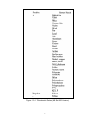
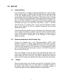
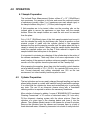
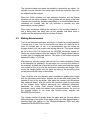
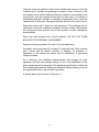
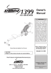
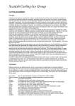
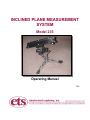
INCLINED PLANE MEASUREMENT
SYSTEM
Model 235
Operating Manual
7/08
1.0 INTRODUCTION
The antistatic property of material is one of the most important factors in
determining the effectiveness of a static control product. However, It is the most
difficult parameter to measure on a consistent and repeatable basis. A number of
different test procedures are currently in use, but the one that has gained
considerable acceptance in the electronics industry is the Modified Inclined Plane
Test.
This test basically measures the charge developed on Teflon and Quartz
cylinders rolled down a sample of test material mounted to a plane set at a
predetermined angle. Teflon and Quartz cylinders are used because they
represent increasingly negative and increasingly positive portions of the
Triboelectric Series. Other materials such as brass and gold plated brass can
also be used. A Series obtained from Mil Std 883 is shown in Figure 1.0-1.
The apparatus required to perform this test utilizes both basic measuring
instruments and several accessory items. The ETS Model 235 Inclined Plane
Measurement System is a complete system specifically designed to perform the
Inclined Plane Test defined in ESDA ADV11.2 Appendix B (large cylinders-std,
small cylinders-optional) in a consistent and repeatable manner. The complete
System includes the following instrumentation and accessories:
1.
2.
3.
4.
5.
6.
7.
8.
Adjustable inclined plane with cylinder release mechanism
Specimen holders (8 ea.)
Teflon and Quartz cylinders (36 ea.) -1”x1” (25.4x25.4mm)
Nanocoulombmeter with 3.25” Faraday cup and foot operated
READ/ZERO switch
Balanced AC Ionizer with foot operated ON/OFF switch
Ultrasonic cleaner
Stainless steel cylinder holding trays
Metal tongs with grounding cable
In addition, a portable charged plate monitor for verifying ionizer balance and an
automatically controlled humidity chamber are also available with the System.
2
Figure 1.0-1: Triboelectric Series (Mil Std 883 Version)
3
2.0 EQUIPMENT DESCRIPTION
The standard Model 235 Inclined Plane Measurement System is supplied with all
the components listed in Section 1.0. However, the System can be ordered with
optional or deleted accessories as required. The following are descriptions of the
various standard components and optional accessories:
2.1
Model 236 Adjustable Inclined Plane
The Model 236 Adjustable Inclined Plane, shown in Figure 2.1-1, consists
of a 0.25” (6mm) thick aluminum plate that forms the plane mounted to a
sturdy steel tripod. The plane is 12” (305mm) long by 4” (102mm) wide and
incorporates a pair of hold-down rails for mounting thick test specimens.
The adjustable post that holds the Plane assembly can be rotated over a
45° arc. The built-in scale enables any desired angle within this arc to be
selected. The stand also can be adjusted for height to accommodate the
different angles selected for the plane.
Removing the mounting rails exposes locating studs for retaining the
removable magnetic stainless steel specimen holders shown in Figure 2.12 supplied with the system.
Figure 2.1-1: Inclined Plane
Located at the top of the Plane is a moveable flap that acts as the release
mechanism for the cylinders. It incorporates a pair of hold-down rails to
accommodate additional test material to equalize the height of thick test
4
specimens. The release mechanism is activated manually by slightly
rotating the knob located on the side of the plane.
The System is supplied with 8 magnetic stainless steel specimen holders
with strip magnets to mount thin specimens. This is sufficient to handle
most testing requirements that usually require either 3 or 6 specimens. The
specimen holders enable the user to pre-mount the test specimens and
then place them into the humidity chamber for conditioning and test. This is
especially convenient when testing thin films. Additional specimen holders
are available as an optional accessory.
Thirty-six pieces each of 1”x1” (25.4x25.4mm) Teflon and Quartz cylinders
are supplied with the system. Each cylinder can be used up to 3 times
before it has to be cleaned. There is a slight difference in the diameters of
the Teflon and Quartz cylinders, and where the exact contact area is
required to compare absolute charge levels, it is recommended that the
cylinder diameters be measured.
Figure 2.1-2: Sample holders and Teflon and Quartz cylinders
2.2 Nanocoulombmeter
The ETS Model 230 Nanocoulombmeter, shown in Figure 2.2-1, is used to
measure the charge on the cylinders after rolling down the plane. The
instrument is powered by two standard 9 Volt alkaline batteries that are
readily accessible from the rear panel. A BAT LO indicator warns of low
battery voltage (<12V). The front panel consists of a 3½ digit LCD readout
with ½” (12mm) numerals, a 3-position rotary RANGE selector switch, a
READ/ZERO switch, a 1.0 Volt CAL output, BAT LO warning indicator,
POWER ON/OFF switch and the BNC Faraday cup INPUT signal
connector.
5
Figure 2.2-1: Model 230 Nanocoulombmeter
The rear panel consists of the battery compartment, optional 115 VAC
Power Module input jack, a GROUND terminal for referencing the
instrument to ground, a remote READ/ZERO output jack, and a Recorder
Output BNC connector.
The foot operated READ/ZERO switch plugs into the remote READ/ZERO
output jack on the rear panel. This enables the user to control the
Nanocoulombmeter while operating the Inclined Plane. The remote switch,
when plugged in, overrides the READ/ZERO switch on the front panel.
A 0-1.99 Volt signal is available at the Recorder Output corresponding to a
0-full scale reading of the RANGE selected.
The Faraday cup consists of 3.25” diameter inner sensing cup and a 4”
(102mm) diameter by 6” (152mm) high outer shell mounted in an
adjustable stand to that enables the user to align the cup angle with the
Inclined Plane. This assembly is shown in Figure 2.1-3. In addition, a
conductive foam pad is inserted in the bottom of the sensing cup to cushion
the shock of the cylinders dropping into it. The cup is connected to the
Nanocoulombmeter via a 3’ (92cm) long Teflon insulated coaxial cable.
6
Figure 2.1-3: Faraday cup mounted in holding fixture
2.3 Ionizer
A balanced AC ionizer is included to neutralize the charge on the test
specimen and the Teflon and Quartz cylinders prior to making a
measurement. The ionizer emits both positive and negative ions. An object
with a positive static charge will draw negative ions from the airflow out of
the ionizer. Conversely, an object with a negative static charge will draw
positive ions from the airflow. Charged objects remaining in the airflow will
remain neutralized. The ions are attracted to the oppositely charged object
and neutralize the charge on the object. The ionizer incorporates a variable
speed fan and a heater. A foot operated power switch is provided to control
the operation of the ionizer while making a measurement.
2.4 Cleaning and Handling Accessories
An ultrasonic cleaner along with a formulated cleaning concentrate,
stainless steel cylinder holding trays, and a pair of metal tongs with ground
lead are supplied as single group of accessories.
2.5 Optional Accessories
The following are additional equipment available for performing the inclined
plane triboelectric test as generally specified:
7
2.5.1 Automatically Controlled Humidity Chamber
The ETS Model 5506 Humidity Control Chamber along with the
ETS Series 5000 Automatic Humidity Controller (not shown),
shown in Figure 2.5-1, provides the controlled humidity
environment of 12 +/- 3% R.H. required.
Figure 2.5-1: Controlled Environment Chamber
2.5.2 Ion Balance Detector
This test requires an ionizer with a balanced ion output. To verify
that the ionizer being used is actually putting out a balanced ion
stream, an ion balance detector is required. This consists of an
ETS Model 212 Static Meter with Model 205C Charged Plate
Detector. When installed onto the Static Meter and placed in front
of the ionizer the system can measure the level of ionizer
imbalance with a resolution of 1 Volt.
Figure 2.5-2: Ion balance monitor
8
3.0 SET-UP
3.1
Inclined Plane
The Inclined Plane is shipped completely assembled, but with the plane
section and the legs in a folded position. Spread the leg of the tripod base
to the fully opened position. Loosen the wing nut on the face of the
nomenclature panel and adjust the plane to the desired angle. Currently,
the 15o setting is the angle specified. Other angles that are used are 30o
and 45o. Another adjustment on the main shaft adjusts the spread of the
legs, which in turn, controls the height of the system. If the thick specimen
hold-down rails are to be used then leave them in place. If not then
remove the two 12” (305mm) rails. In most cases the specimen holders
will be used. Material too thick for magnetic attachment can be easily
attached using tape.
The release flap also contains a pair of hold-down rails. These are used to
mount a piece of material or a spacer to provide a minimal contact surface
to the cylinder during activation when thick samples are being tested. A
spacer is provided to compensate for the thickness of the magnetic
specimen holders.
3.2
Nanocoulombmeter and Faraday Cup
Connect the Faraday cup to the Nanocoulombmeter INPUT BNC
connector using the 3’ (92cm) Teflon insulated coaxial cable provided.
Plug the connector from the READ/ZERO foot switch into the mating jack
located on the rear panel of the instrument. If a chart recorder or other
type of recording device is being used, connect it to the BNC connector on
the rear panel at this time.
Place the Faraday cup into the acrylic base and adjust the angle of the
cup so that a cylinder rolled down the Inclined Plane will fall into the cup
without hitting the side of the cup. The angle is adjusted and locked in
place by first loosening, then tightening the screw on the side of the hinge.
3.3
Ionizer
Plug the ionizer power cord into the foot switch AC receptacle. Plug the
AC plug from the switch into a 110 VAC outlet. A convenient location for
the ionizer, when testing is being performed in a humidity chamber, is
towards the right rear of the chamber behind the Inclined Plane.
9
4.0 OPERATION
4.1 Sample Preparation
The Inclined Plane Measurement System utilizes 4” x 12” (102x305mm)
test specimens. Cut samples to this size and mount the required number
of specimens (usually, either 3 or 6 specimens per each sample type) to
the sample holders using the ½ “ (12.5mm) wide magnetic strips.
If thick samples are to be tested, either use the mounting rails on the
inclined plane to secure the specimens or tape them onto the sample
holders. When the sample holders are used the rails must be removed
from the plane.
Cut a 1’x3.5” (25x89mm) piece of the thick sample material and mount it
onto the release flap using the hold-down rails. Adjust its position so that
minimal contact is made with the cylinder placed in the separation
between the flap and the sample mounted onto the plane when the flap is
raised to release the cylinder. When using the sample holder electrodes,
install the supplied spacer onto the flap. If thick material is taped to the
sample holders then add a piece to the spacer.
It is important to minimize any charging of the cylinder due to the action of
the release mechanism. There may have to be some adjustments to the
exact location of the spacers to achieve minimum parasitic charging and a
smooth roll of the cylinder down the plane and into the Faraday cup.
After preparing the samples, place them into the humidity control chamber
set at a relative humidity of 12 +/- 3% R.H. for a period of 48 hours prior to
test. Current electronic and military standards use 12% as the test
environment, but other humidity levels may also be used.
4.2
Cylinder Preparation
The test cylinders can be very easily charged through handling and can be
altered when placed in contact with material having transferable coatings.
It is critical that the cylinders be clean and neutralized prior to performing
any tests. The use of an ultrasonic cleaner along with a formulated
cleaning solution is required to achieve the necessary cleanliness.
Mix a solution of cleaner by adding 1 ounce of “BRANSON GP Formulated
Cleaning Concentrate” to 10 ounces of deionized water (10:1 mix ratio).
Fill the ultrasonic cleaning system with the above mixture. Place the
cylinders of a given type in the cleaning basket and lower it into the
cleaner. The cylinders should remain in the cleaner for at least 5 minutes.
Remove the cylinders from the cleaner and immerse them in a bath of
fresh deionized water, followed by immersion into a bath of methyl alcohol.
10
The cylinder surface must never be handled or touched by any object. If a
cylinder must be touched, the metal tongs should be used and then only
the ends should be touched.
Place the Teflon cylinders into one stainless container and the Quartz
cylinders into the other container. If the cylinders are not going to be used
or placed into a humidity chamber immediately, it is recommended that the
containers be covered with the lids provided to prevent any dust
accumulation on the cylinders.
Place open containers holding the cylinders in the humidity chamber, if
one is being used, the same time as the samples and allow them to
condition at the desired humidity for at least 48 hours.
4.3
Making Measurements
Turn on the Nanocoulombmeter and allow it to warm-up for approximately
1 minute prior to use. Turn on the ionizer and allow it to warm-up for at
least 10 minutes prior to test. It is recommended that the ionizer be
plugged directly into the power outlet during warm-up. The ionizer should
be set to the LOW Fan Speed and the HEATER should be turned off.
Check the ionizer balance using the optional ETS Charged Plate Detector
or other type of charged plate monitor. The output of the ionizer should be
balanced to within +/-10 Volts.
After warm-up, plug the ionizer back into the foot switch receptacle. Select
a test specimen by grabbing it by the edges (do not touch the surface of
the material). Activate the ionizer with the foot switch and hold the sample
test surface in front of it for a few seconds to neutralize any charge. Then
mount the sample holder onto the plane by lining up the mounting studs
on the plane with the holes in the holders.
Take a cylinder from the stainless steel container by grabbing the edges
with the grounded metal tongs. Activate the ionizer and slowly pass the
cylinder in front of the air stream, then place the cylinder onto the release
flap, centered latterly. With the ionizer still activated, place the right hand
on the release knob. Without performing any additional operations,
deactivate the ionizer. Wait several seconds and with minimum
movement, gently rotate the release knob counterclockwise. As soon as
the cylinder begins to roll down the inclined plane, depress the
READ/ZERO foot switch.
The cylinder should roll straight down the plane and into the cup without
hitting anything on the plane or the edge of the cup. After approximately 2
seconds read the charge on the Nanocoulombmeter DPM and then
release the READ/ZERO foot switch.
11
Take the tongs and grab the sides of the cylinder and remove it from the
Faraday cup. A cylinder can generally be reused 3 times. However, if the
test sample has a surface treatment that can transfer to the cylinder, such
as pink poly, then the cylinder should only be used once. If a cylinder is
accidentally dropped, handled or otherwise compromised, then it must be
replaced with a clean one. Damaged cylinders should not be used for test.
Repeat the above test 3 times for each specimen. If the readings are not
reasonably close then additional readings should be taken. Re-evaluate
the testing procedure and also use a fresh cylinder for each subsequent
measurement.
Place the used cylinders into a third container. DO NOT PUT THEM
BACK INTO THE ORIGINAL CONTAINERS.
Repeat the above procedure for each of the test specimens.
Generally, each specimen will be tested 3 times with the Teflon cylinder
and 3 times with the Quartz Cylinder. In addition, for indication, 3
specimens of the sample are tested, and for certification, 6 specimens
should be tested.
As a minimum, the individual measurements, the average for each
specimen and then the average charge for all of the specimens of the
given sample should be recorded. The individual specification to which the
test is being performed will dictate any additional data processing, such as
the standard deviation, that should be provided.
A sample data sheet is shown in Figure 4.3-1
12
Figure 4.3-1: Sample data sheet
5.0 CALIBRATION
The only components of the Test System that require calibration are the
Nanocoulombmeter and the ionizer.
5.1
Nanocoulombmeter Calibration
The Model 230 Nanocoulombmeter is calibrated at the factory using
instrumentation traceable to N.I.S.T. Periodic recalibration of any
measuring is strongly recommended. In most applications, recalibration
should be performed on a yearly basis. Contact ETS for recalibration
services.
13
The user can check the calibration of the instrument at any time by using
the supplied 0.10 uf, 1% polystyrene capacitor. This capacitor, when
charged to 1.00 Volt, will produce a reading on the DPM of 100 +/- 2 nC.
Connect the clip lead of the calibration check capacitor provided to the
ground terminal on the rear panel or to the outer shell of the Faraday cup.
Select the 200 nC RANGE. Touch the lead from the capacitor to the CAL
output connector on the front panel. Place the READ/ZERO switch in the
READ mode and then touch the capacitor lead to the inner can or directly
to the BNC input connector. The DPM should read 100 +/- 2nC.
The other ranges can also be checked with the same capacitor using an
external precision voltage source. 10 Volts applied to the capacitor will
produce a reading of 1000 nC on the 2000 nC RANGE and 0.10 Volts
applied to the capacitor will produce a reading of 10 nC on the 20nC
RANGE. Additional points can be checked by using different voltage
and/or capacitor values (must be a precision, low leakage type). Using the
relationship
Q(nC) = C(uf)V(volts)
any reading on the DPM can be obtained.
5.2
Ionizer Calibration
The ionizer supplied with the System has an ion output that is inherently
balanced by design. As a result, there are no calibration adjustments. If the
measurement of the ionizer output shows excessive imbalance, refer to the
section in the Ionizer Instruction Manual for “Trouble Shooting Ion Output
and Balance Problems”.
6.0 MAINTENANCE
The Model 235 Inclined Plane Measurement Test System requires a minimum of
maintenance. However, when servicing the individual components, normal care
and safety precautions should be adhered to. If any piece of equipment must be
returned to ETS for service or recalibration, a Return Material Authorization
(RMA) must first be obtained. The equipment must be packed in adequate
packaging to avoid shipping damage and incurring additional cost to repair.
6.1
Inclined Plane
The Inclined Plane should require no maintenance except for an
occasional cleaning of the plane surface. The plane is aluminum with a
black anodized finish. Abrasive compounds should never be used. Wipe
the surface with a mild liquid household cleaner or isopropyl alcohol.
14
Return the inclined Plane to ETS for service if there are any mechanical
malfunctions.
6.2
Nanocoulombmeter
The ETS Model 230 Nanocoulombmeter is designed with a low current
circuit to ensure many hours of use from a single pair of 9 Volt Alkaline
batteries. When the battery voltage drains down to 12 Volts the front panel
BAT LO LED illuminates. At this time the batteries should be replaced to
retain measurement accuracy. For additional information, please refer to
the Model 230 Instructional Manual.
To change the batteries, remove the battery cover mounted on the rear
panel. The batteries are connected to the instrument by a pair of standard
9 Volt battery clips. Both batteries should be replaced at the same time.
Replace the battery cover.
If the instrument fails to operate properly it should be returned to ETS for
repair and recalibration.
6.3
Ionizer
Refer to the ionizer manufacturer’s instruction manual.
6.4
Ultrasonic Cleaner
Refer to the ultrasonic cleaner manufacturer’s instructional manual.
7.0 SPECIFICATIONS
Model 230:
Faraday Cup & System
Ranges: 20, 200, 2000nC
Resolution: 0.01, 0.1, 1.0nC
Accuracy: 2.0% full scale (max), ±1 digit
Readout: 3½-digit LCD, ½" (12mm) numeric
Drift: <0.05nC/minute
Zero: Front panel or optional foot switch.
Recorder output: 0-±1.99V, BNC connector
Calibration output: +1.00 Volts, ±1%
Power: Battery, 2 ea, 9 Volt Alkaline, (20 hrs typical)
AC power module: 95-260VAC, 50/50Hz
Operating environment: 0-60% RH
Dimensions: 7.5"Wx8.0"Dx1.75"H (191x203x45mm)
Weight: 2 lbs.
Electrical connection: Std. BNC
Model 231: Inner cup dia.: 3.1” dia.x4”D (80x102mm)
Overall dimensions: 4” dia.x6”H (102x152mm)
Model 235: System includes the following:
Model 236 Inclined Plane, 8 Sample Holders,
Adj. Cup angle fixture, 36 ea. 1”x1” (25x25mm) Teflon
& quartz cylinders, ionizer with foot switch, ultrasonic
cleaner, plus accessories
Calibration capacitor: 0.10 μf, ±1% (Low Leakage)
Options: Small cylinders, 0.5”x1” (12.5x25mm)
Static meter with charged plate detector
7/08
15
8.0 WARRANTY
Electro-Tech Systems, Inc. warrants its equipment, accessories and parts of its
manufacture to be and remain free from defects in material and workmanship for
a period of one (1) year from date of invoice and will, at the discretion of Seller,
either replace or repair without charge, F.O.B. Glenside, similar equipment or a
similar part to replace any equipment or part of its manufacture which, within the
above stated time, is proved to have been defective at the time it was sold. All
equipment claimed defective must be returned properly identified to the Seller (or
presented to one of its agents for inspection). This warranty only applies to
equipment operated in accordance with Seller’s operating instructions.
Seller’s warranty with respect to those parts of the equipment that are purchased
from other manufacturers shall be subject only to that manufacturer’s warranty.
The Seller’s liability hereunder is expressly limited to repairing or replacing any
parts of the equipment manufactured by the manufacturer and found to have
been defective. The Seller shall not be liable for damage resulting or claimed to
result from any cause whatsoever.
This warranty becomes null and void should the equipment, or any part thereof,
be abused or modified by the customer of if used in any application other than
that for which it was intended. This warranty to replace or repair is the only
warranty, either expressed or implied or provided by law, and is in lieu of all other
warranties and the Seller denies any other promise, guarantee, or warranty with
respect to the equipment or accessories and, in particular, as to its or their
suitability for the purposes of the buyer or its or their performance, either
quantitatively or qualitatively or as to the products which it may produce and the
buyer is expected to expressly waive rights to any warranty other than that stated
herein.
ETS must be notified before any equipment is returned for repair. ETS will issue
an RMA (Return Material Authorization) number for return of equipment.
Equipment should be shipped prepaid and insured in the original packaging. If
the original packaging is not available, the equipment must be packed in a
sufficiently large box (or boxes if applicable) of double wall construction with
substantial packing around all sides. The RMA number, description of the
problem along with the contact name and telephone number must be included in
formal paperwork and enclosed with the instrument. Round trip freight and
related charges are the owner’s responsibility.
WARNING:
WOODEN CRATES MUST NOT BE USED. PACKAGING OF DELICATE
INSTRUMENTS IN WOODEN CRATES SUBSTANTIALLY INCREASES THE
CONTENT’S SUSCEPTIBILITY TO SHOCK DAMAGE. DO NOT PLACE
INSTRUMENTS OR ACCESSORIES INSIDE OTHER INSTRUMENTS OR
CHAMBERS.
ELECTRO-TECH
SYSTEMS,
INC.
WILL
NOT
ASSUME
RESPONSIBILITY FOR ADDITIONAL COST OF REPAIR DUE TO DAMAGE
INCURRED DURING SHIPMENT AS A RESULT OF POOR PACKAGING.
16