1
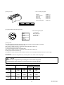
RYS-L Type
User's Manual
MHT259a (Engl.)
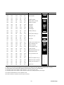
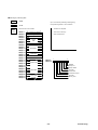
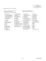
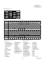
CONTENTS
SAFETY INSTRUCTION
1. GENERAL ・・・・・・・・・・・・・・・・・・・・・・・・・・・・・・・・・・・・
・・・・・・・・・・・・・・・・・・・・・・・・・・・・・・・・ ・・・・ 1-1
1.1 Outline ・・・・・・・・・・・・・・・・・・・・・・・・・・・・・・・・・・・・・・・ 1-1
1.2 System configuration ・・・・・・・・・・・・・・・・・・・・・・・・・・・ 1-3
1.3 Functions ・・・・・・・・・・・・・・・・・・・・・・・・・・・・・・・・・・・・・ 1-5
1.4 Explanation of model type ・・・・・・・・・・・・・・・・・・・・・・・ 1-6
2. SPECIFICATIONS ・・・・・・・・・・・・・・・・・・・・・・・・・・・・・ 2-1
2.1 Motor・・・・・・・・・・・・・・・・・・・・・・・・・・・・・・・・・・・・・・・・・ 2-1
2.2 Amplifier ・・・・・・・・・・・・・・・・・・・・・・・・・・・・・・・・・・・・・・ 2-11
2.3 Torque-speed data ・・・・・・・・・・・・・・・・・・・・・・・・・・・・・ 2-16
3. INSTALLATION ・・・・・・・・・・・・・・・・・・・・・・・・・・・・・・・ 3-1
3.1 Motor・・・・・・・・・・・・・・・・・・・・・・・・・・・・・・・・・・・・・・・・・ 3-1
3.2 Amplifier ・・・・・・・・・・・・・・・・・・・・・・・・・・・・・・・・・・・・・・ 3-4
3.3 External dimensions ・・・・・・・・・・・・・・・・・・・・・・・・・・・・ 3-9
4. TERMINAL DIAGRAMS AND WIRING ・・・・・・・・・・・・・ 4-1
4.1 Amplifier, motor and optional devices layout ・・・・・・・・ 4-1
4.2 Commercial power supply ・・・・・・・・・・・・・・・・・・・・・・・ 4-6
4.3 Wiring between motor and pulse encoder ・・・・・・・・・・ 4-7
4.4 Host interface (I/F)・・・・・・・・・・・・・・・・・・・・・・・・・・・・・・ 4-10
4.5 External connection diagrams (normal, example) ・・・・ 4-26
5. CONTROL FUNCTIONS ・・・・・・・・・・・・・・・・・・・・・・・・ 5-1
5.1 Summary ・・・・・・・・・・・・・・・・・・・・・・・・・・・・・・・・・・・・・ 5-1
5.2 Run command ・・・・・・・・・・・・・・・・・・・・・・・・・・・・・・・・・ 5-3
5.3 Manual operation ・・・・・・・・・・・・・・・・・・・・・・・・・・・・・・・ 5-8
5.4 Origin return ・・・・・・・・・・・・・・・・・・・・・・・・・・・・・・・・・・・ 5-13
5.5 Auto start ・・・・・・・・・・・・・・・・・・・・・・・・・・・・・・・・・・・・・ 5-19
5.6 Signal for safety ・・・・・・・・・・・・・・・・・・・・・・・・・・・・・・・・ 5-39
5.7 Incidental functions ・・・・・・・・・・・・・・・・・・・・・・・・・・・・・ 5-46
5.8 IQ area ・・・・・・・・・・・・・・・・・・・・・・・・・・・・・・・・・・・・・・・ 5-59
5.9 WB area ・・・・・・・・・・・・・・・・・・・・・・・・・・・・・・・・・・・・・・ 5-68
5.10 General-purpose communication・・・・・・・・・・・・・・・・・ 5-74
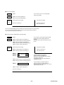
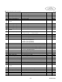
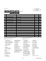
9.4 SX bus (SX bus direct connection) ・・・・・・・・・・・・・・・・ 9-8
9.5 T-link (T-link direct connection) ・・・・・・・・・・・・・・・・・・・ 9-11
9.6 General-purpose communication (RS485 interface) ・・ 9-14
10. INSPECTION AND MAINTENANCE ・・・・・・・・・・・・・・ 10-1
10.1 Inspection・・・・・・・・・・・・・・・・・・・・・・・・・・・・・・・・・・・・ 10-1
10.2 Memory backup ・・・・・・・・・・・・・・・・・・・・・・・・・・・・・・・ 10-1
10.3 Fault display・・・・・・・・・・・・・・・・・・・・・・・・・・・・・・・・・・ 10-2
10.4 Items to inquire when faulty ・・・・・・・・・・・・・・・・・・・・・ 10-14
10.5 Others informations・・・・・・・・・・・・・・・・・・・・・・・・・・・・ 10-15
11. PERIPHERAL DEVICES ・・・・・・・・・・・・・・・・・・・・・・・ 11-1
11.1 Cables ・・・・・・・・・・・・・・・・・・・・・・・・・・・・・・・・・・・・・・ 11-3
11.2 Auto circuit breaker (FAB, MCCB), earth leakage
circuit breaker (ELCB) and magnetic
contactor (MC) ・・・・・・・・・・・・・・・・・・・・・・・・・・・・・・・・・・・・ 11-4
11.3 Surge suppressor (surge killer) ・・・・・・・・・・・・・・・・・・ 11-4
11.4 Power filter ・・・・・・・・・・・・・・・・・・・・・・・・・・・・・・・・・・・ 11-5
11.5 AC reactor (reactor for impedance matching) ・・・・・・ 11-6
11.6 External braking resistor ・・・・・・・・・・・・・・・・・・・・・・・・ 11-6
11.7 DC reactor ・・・・・・・・・・・・・・・・・・・・・・・・・・・・・・・・・・・ 11-7
11.8 Optional cables, connector kits, battery and
external braking resistors ・・・・・・・・・・・・・・・・・・・・・・・・・・・ 11-8
12. APPENDIXES・・・・・・・・・・・・・・・・・・・・・・・・・・・・・・・・ 12-1
12.1 Model type selection ・・・・・・・・・・・・・・・・・・・・・・・・・・・ 12-1
12.2 Example of program ・・・・・・・・・・・・・・・・・・・・・・・・・・・ 12-10
12.3 Control block diagram ・・・・・・・・・・・・・・・・・・・・・・・・・・ 12-18
12.4 Letter symbols and abbreviated words ・・・・・・・・・・・・ 12-20
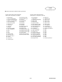
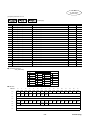
6. PARAMETER SETTING ・・・・・・・・・・・・・・・・・・・・・・・・・ 6-1
6.1 List of parameter ・・・・・・・・・・・・・・・・・・・・・・・・・・・・・・・ 6-2
6.2 Basic parameter ・・・・・・・・・・・・・・・・・・・・・・・・・・・・・・・ 6-17
6.3 System parameter・・・・・・・・・・・・・・・・・・・・・・・・・・・・・・ 6-35
7. KEYPAD PANEL ・・・・・・・・・・・・・・・・・・・・・・・・・・・・・・ 7-1
7.1 Display ・・・・・・・・・・・・・・・・・・・・・・・・・・・・・・・・・・・・・・・ 7-1
7.2 Function list ・・・・・・・・・・・・・・・・・・・・・・・・・・・・・・・・・・・ 7-3
7.3 Sequence mode ・・・・・・・・・・・・・・・・・・・・・・・・・・・・・・・ 7-5
7.4 Monitor mode ・・・・・・・・・・・・・・・・・・・・・・・・・・・・・・・・・・ 7-10
7.5 Parameter edit mode ・・・・・・・・・・・・・・・・・・・・・・・・・・・ 7-15
7.6 Positioning data edit mode ・・・・・・・・・・・・・・・・・・・・・・・ 7-18
7.7 Test running mode ・・・・・・・・・・・・・・・・・・・・・・・・・・・・・ 7-20
8. SETTING OF POSITIONING DATA・・・・・・・・・・・・・・・・ 8-1
8.1 Setting contents ・・・・・・・・・・・・・・・・・・・・・・・・・・・・・・・・ 8-1
8.2 Starting ・・・・・・・・・・・・・・・・・・・・・・・・・・・・・・・・・・・・・・・ 8-5
8.3 Setting change ・・・・・・・・・・・・・・・・・・・・・・・・・・・・・・・・・ 8-6
8.4 Response time ・・・・・・・・・・・・・・・・・・・・・・・・・・・・・・・・・ 8-6
9. TEST (TRIAL) RUNNING OPERATION ・・・・・・・・・・・・ 9-1
9.1 Preparation・・・・・・・・・・・・・・・・・・・・・・・・・・・・・・・・・・・・ 9-1
9.2 Motor・・・・・・・・・・・・・・・・・・・・・・・・・・・・・・・・・・・・・・・・・ 9-3
9.3 Basic type (DI/DO position) ・・・・・・・・・・・・・・・・・・・・・・ 9-4
MHT259a (Engl.)
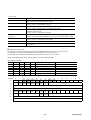
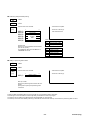
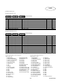
SAFETY INSTRUCTIONS
In all stages of the basic planning of this equipment, its transport, installation, operation, maintenance and check, reference must be made to
this manual and other related documents. The correct understanding of the equipment, information about safety and other related
instructions are essential for this system.
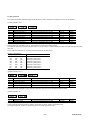
Cautionary indications DANGER and CAUTION are used in this manual to point out particular hazards and to highlight some unusual
information which must be specially noted.
Cautionary indications
Description
DANGER
Indicates that death or severe personal injury will result if proper
precautions are not taken.
CAUTION
Indicates that personal injury or property damage alone will result if
proper precautions are not taken.
Pictorial symbols are used as necessary.
Pictorial symbol
Description
Pictorial symbol
Description
Do not disassemble
Electrical shock hazard warning
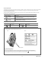
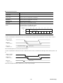
Warning display
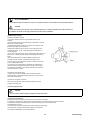
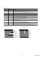
The warning display in Fig. B is located at the arrows in Fig. A.
Fig. A
Fig. B
Warning display
Fig. B shows following contents :
There is a risk of electric shock.
Do not touch the amplifier when a commercial power is applied and for at least five minutes after de-energization.
Be sure to ground {applicable for Japan only : grounding equal to 3rd class grounding structure of Japanese standard
(grounding resistance 100 [Ω] or less)} must be connected with the terminal marked “
“.
(i)
MHT259a (Engl.)
DANGER
●Prior to inspection, turn off power and wait for at least five minutes.
Otherwise, there is a risk of electric shock.
●Do not touch the amplifier when the commercial power is supplied. Otherwise, there is a risk of electric shock.
CAUTION
●Do not disassemble the motor. Otherwise, the operation may be abnormal, thereby damaging the coupled machine.
●Do not hit the motor with hammer or any other instruments. The integrated (built-in) encoder may break causing the motor
to run at an excessive speed.
●Do not connect a commercial power supply directly to the motor. Otherwise, it may break.
●Supplying other than 200 [V] or 100 [V] (according to input voltage class of amplifier) to the amplifier may break it.
●Do not turn on and off the commercial power repeatedly. Otherwise, the amplifier rectifier may break.
●The motor must be firmly tightened to the mounting base or the driven machine. If rapid acceleration or deceleration is
attempted without this firm tightening, the motor may become dislocated.
●Withstand voltage and insulation test with megger must not be conducted.
Products introduced in this manual have not been designed or manufactured for such applications in a system or equipment that will
affect human bodies or lives. Customers, who want to use the products introduced in this manual for special systems or devices
such as for atomic-energy control, aerospace use, medical use, and traffic control, are requested to consult the Fuji. Customers
are requested to prepare safety measures when they apply the products introduced in this manual to such systems or facilities that
will affect human lives or cause severe damage to property if the products become faulty.
The technical data and dimensions are subject to change without notice in the individual pages of this document.
The illustrations are for reference-only.
The company names and product names described herein are generally the registered trade names.
Although this manual indicates technical units given in SI units, the indications (rating plate, etc.) on the products themselves may be in
units other than SI units.
( ii )
MHT259a (Engl.)
1. GENERAL
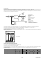
1.1 Outline
The FALDIC-α series which corresponds to a host interface is an AC servo system for motion-control necessary for a driven machine.
(1) Model type in this manual
(a) Amplifier (*) : RYS□□□S3-LPS□, LSS□, LTS□ and LRS□
(b) Motor (*) : GYC□□□DC1-S*−****
GYS□□□DC1-S*−****
(c) Gear head : GYN□□□SAG-G□□
GRN□□□SAG-G□□
(2) Main features of product
(a) Save-wiring 16 bit serial pulse encoder (encoder) (65536 pulses/rev.)
(i) On the motor, an encoder for any of INC and ABS systems is mounted.
(ii) If a battery is mounted on the amplifier, it is usable as ABS system.
(iii) Encoder cabling consists of 2 wires for power supply and 2 for signal,
of totally 4 wires. For ABS system, 2 wires for battery must be added.
(iv) A motor of a different output [kW] can be driven without changing the
encoder setting provided that it has a rated output of frame No. (size)
equal to the output to apply, one step smaller or greater. Refer to 10.3 (3) (d) .
(v) The basic resolution is 65536 pulses/rev., and the frequency dividing
output is 16 to 16384 pulses/rev.
Encode cable
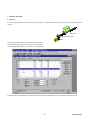
(b) Preparing a PC (*) loader
(i) Servo system support tools capable of controlling the para. (*) editing, monitoring, test
(trial) running, etc. are available.
(ii) Fault diagnostic function alarm can be detected and fault cause covering the mechanical
equipment system can be assumed.
(*) Amplifier : Servo-amplifier
Motor : Servo-motor
PC : Personal computer
Para. : Parameter(s)
1-1
MHT259a (Engl.)
C
I
D
L
A
F
C
I
D
L
A
F
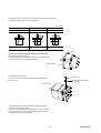
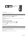
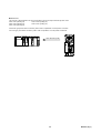
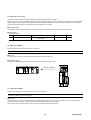
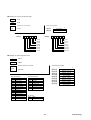
(c) Closely mountable amplifiers
(i) Several amplifiers can be mounted sidewise spaced by less than 5 [mm]
between themselves. In that case, however, the operation duty is not
continuous but 80%ED. Refer to 3.2 (2) .
(ii) Control power supply input terminals are provided. Maintenance is
available at a status where the main circuit power supply is turn off.
(iii) PN terminals for harmonics suppression are provided. A DC
reactor can be mounted.
(iv) A keypad (touch) panel is provided.
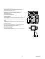
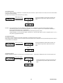
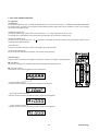
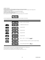
(v) You can select a control function from 3 types:
1) Pulse train input /speed control type (RYS-V type amplifier : Input
frequency 500 [kHz] max.)
2) Linear positioning function (RYS-L type amplifier : Maximum command
value ± 79,999,999)
A linear positioning system combined with ball-screw or other mechanisms.
3) Rotation indexing system (RYS-R type amplifier : Maximum indexing number
30000)
A rotation indexing system combined with ATC, tool magazine, etc. or other
mechanisms.
RYS201S3-VVS
RYS201S3-LPS
RYS401S3-LPS
MODE
ESC
K80791543
SHIFT
ENT
CHARGE
MODE
ESC
K80791234
SHIFT
ENT
CHARGE
L1
L1
L2
L2
L3
L3
DB
DB
P1
P1
P+
P+
N
N
U
U
V
V
W
W
(d) Cubic/slim type motors
Cubic type of approximately half the depth of our basic type motor and slim
type of flange of approximately half size are obtained.
(i) The degree of protection (motor enclosure protection) is IP55.
Optionally, IP67 can be supplied.
(ii) 0.03 to 5 [kW] are available.
(iii) Acceptable acceleration vibration is 49 [m/s2] and the slit plate material of
16 bit serial encoder is non-glass film.
1-2
MHT259a (Engl.)
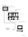
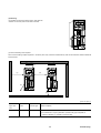
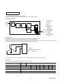
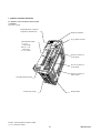
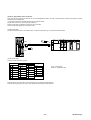
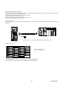
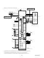
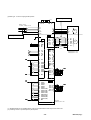
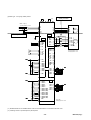
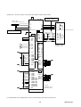
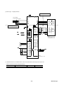
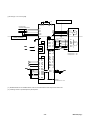
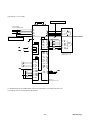
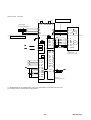
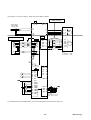
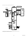
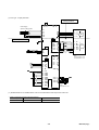
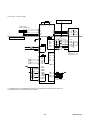
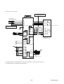
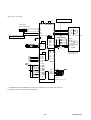
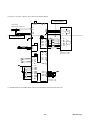
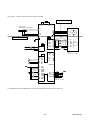
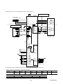
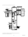
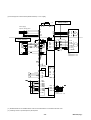
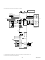
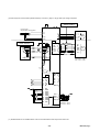
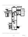
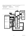
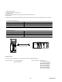
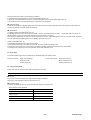
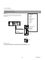
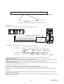
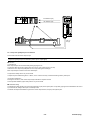
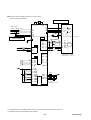
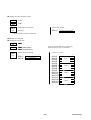
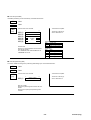
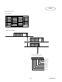
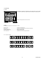
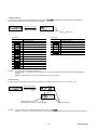
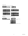
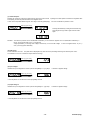
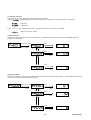
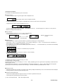
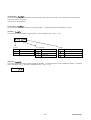
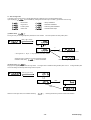
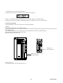
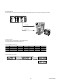
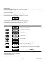
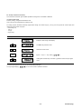
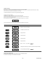
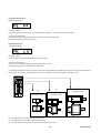
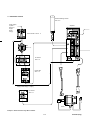
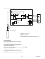
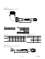
1.2 System configuration
The following illustrates related devices of FALDIC-α system.
Programmable operation display (POD)
UG20
SYSTEM
F1
F1
F2
F2
F3
F3
F4
F4
F5
F5
Programmable logic controller (PLC)
MICREX-SX
MICREX-F
FLEX-PC
F6
F6
F7
F7
SX
SCPU32
APS30
RUN
RUN
TERM
TERM
SLV
SLV
PWR
STOP
STOP
ONL
ONL
ERR
ERR
SCPU32
ONL
ONL
ERR
ERR
RUN
RUN
TERM
TERM
SLV
SLV
RUN
RUN
ALM
ALM
BAT
BAT
ONL
ONL 00 11 22 33 44 55 66 77
ONL
ONL
ERR
ERR 88 99 101112131415
101112131415
ERR
ERR
RUN
RUN
ALM
ALM
BAT
BAT
STOP
STOP
ALM
CPU
CPU
No.
No.
ONL
ONL 00 11 22 33 44 55 66 77
ONL
ONL
ERR
ERR 88 99 101112131415
101112131415
ERR
ERR
CPU
CPU
No.
No.
PH
20
20
PL
LOADER
CH1
CH1
EMG
EMG +OT
+OT -OT
-OT
CH2
CH2
CH
CH
No.
No.
DA
LOADER
11
B/A
B/A
PE1
SX
APS30
ONL
ONL
ONL
ONL
ONL
ONL
ERR
ERR
ERR
ERR
ERR
ERR
CH1
CH1
EMG
EMG +OT
+OT -OT
-OT
CH2
CH2
HP2
ONL
ONL 00 11 22 33 44 55 66 77
ONL
ONL 00 11 22 33 44 55 66 77
ONL
ONL
ERR
ERR 88 99 101112131415
101112131415
ERR
ERR 88 99 101112131415
101112131415
ERR
ERR
PWR
ALM
FH
FL
20
20
1
2
3
4
TL1
AS1
11
B/A
B/A
MP2
CH2
CH1
JP1
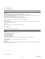
(continue to the following page)
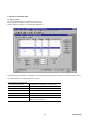
General-purpose PC
[Programming support tool]
・D300win (MICREX-SX)
・Screen editor (UG)
・Servo-loader (FALDIC-α)
1-3
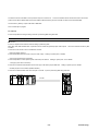
MHT259a (Engl.)
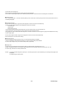
C
I
D
L
A
F
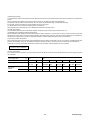
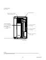
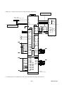
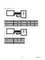
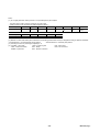
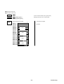
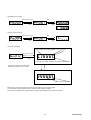
RYS401S3-LPS
MODE
ESC
K80791543
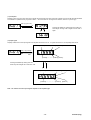
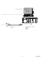
Amplifier
RYS
SHIFT
ENT
CHARGE
L1
L2
L3
DB
P1
P+
N
U
V
W
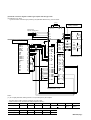
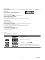
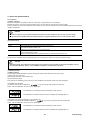
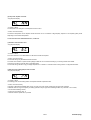
(continued from the
preceding page)
Option cable
WSC
Option cable
WSC
Motor
GYC
GYS
1-4
MHT259a (Engl.)
1.3 Functions
The FALDIC-α series has 3 types of control function for particular applications.
(1) RYS-V type : Pulse train/speed control (velocity)
Maximum input frequency 500 [kHz]
Rotates according to pulse train from host control equipment, or
speed command from encoder or variable resistor.
The host interface has :
・DI/DO speed (minimum DI/DO),
・SX bus type,
・Open network, etc.
(2) RYS-L type:
:Linear positioning system (linear motion)
Maximum command value ± 79,999,999
The amplifier can compose a linear positioning system,
combined with ball-screw, timing belt, rack and pinion or other
mechanisms.
As positioning data, 99 sets (points) of position, current
(present) position output, immediate positioning, M-code
output etc. can be registered.
The host interface has:
・DI/DO position (expanded DI/DO),
・SX bus type,
・T-link type,
・Open network, etc.
(3) RYS-R type:
:Rotation indexing system (rotation)
Maximum indexing number 30000
The amplifier can compose a rotation indexing system,
combined with ATC, tool magazine, loader/unloader, etc. or
other mechanisms.
The rotation indexing system is usable for shorted route control,
2nd origin, one-point halt, single-direction infinite rotation, etc.
The host interface has:
・DI/DO position (expanded DI/DO),
・SX bus type,
・T-link type,
・General-purpose communication (RS485 interface),
・Open network, etc.
1-5
MHT259a (Engl.)
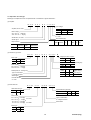
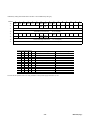
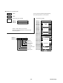
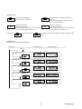
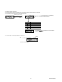
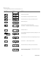
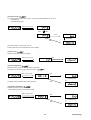
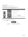
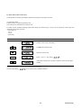
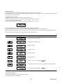
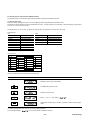
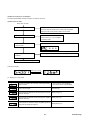
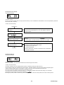
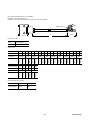
1.4 Explanation of model type
Model type of amplifier and motor is expressed with a combination of figures and letters :
(a) Amplifier
R
Y
S
2
0
1
S
3
-
L
P
S
6
Input voltage
Amplifier, RYS : basic
Phase
Volt.
Figure
Motor output
201 : 20×10 1= 200 [W]
300 : 30×10 0= 30 [W]
Single
100
6
Encoder detector
S : 16 bit
Series letter, S : basic
Host interface (I/F)
Series figure
I/F
Major function
Function Linear
Rotation Pulse train/
positioning index
speed control
Letter
3
200
−
L
R
DI/DO
speed
Letter V
SX
position bus
P
S
JPCN
1
J
RS
485
Tlink
Device
Net
R
T
D
V
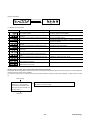
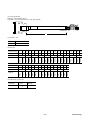
(b) GYS/GYC type motor
G
Y
S
2
0
1
D
C
1
-
S
6
A -
B
Integral provision of brake
Motor type
Type
Slim
Letters GYS
With
Letter B
Cubic
GYC
Without
−
Cylindrical shaft extension, providing key:
With
Letter A
Motor output
201 : 20×101 = 200 [W]
300 : 30×100 = 30 [W]
Without
B
Input voltage of amplifier
Rated speed, D : 3000 [r/min]
Phase 3
Singl
e
Type of construction
C : Flange-mounted
Volt.
100
200
Figure −
6
Single, 100 [V]
or
3-ph. 200 [V]
8
Series figure
Encoder detector
S : 16 bit
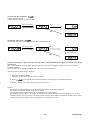
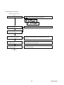
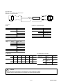
(c) Gear-head unit
G
Y
N
2
0
1
S
A G
Gear-head unit type
Type
GYN GRN
Letter GYN GRN
s
Motor output
201 : 20×101 = 200 [W]
300 : 30×100 = 30 [W]
.20 : 20×101 = 200 [W]
.40 : 40×101 = 400 [W]
-
G
0
9
Speed reduction gear ratio
Gear ratio
Figures and letter
For GYN
Type of construction
G : Flange-mounted
For GRN
Series letter
1/9
G09
1/15
G15
1/25
G25
Motor type
Type
Letter
Slim
S
Cubic
C
1-6
MHT259a (Engl.)
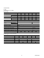
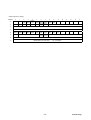
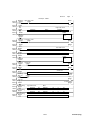
2. SPECIFICATIONS
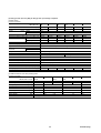
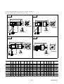
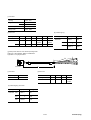
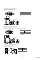
2.1 Motor
(1) Cubic type motor (0.1 to 5 [kW])
(a) Basic design
(i) 0.1 to 1.5 [kW]
Type
Rated output
Rated torque
Speed
GYC□□□DC1-SA
[kW]
[N • m]
[r/min] Rated
Max.
Max. (breakdown) torque (*3)
[N • m]
-3
2
Moment of inertia of motor rotor (×10 ) J[kg • m ]
Current
[A] Rated
Max. (*3)
Winding insulation class
Operation duty type
Degree of enclosure protection
Motor power
Electrical connection
terminals
Encoder detector
Temp. detection
Type of construction (mounting)
Shaft extension, cylindrical
Final color for external non-machined surface
Pulse encoder
Vibration level, peak to peak amplitude
Install location
Ambient climatic conditions
2
Acceleration vibration, acceptable (max.) [m/s ]
Mass (weight)
[kg]
External dimension
101
201
401
751
0.1
0.2
0.4
0.75
0.318
0.637
1.27
2.39
3000
5000
0.955/1.43 1.91/2.87
3.82/5.73
7.17/10.7
0.00538
0.0216
0.0412
0.121
1
1.5
2.6
4.8
3/4.5
4.5/6.8
7.8/11.8
14.4/21.6
B
Continuous
Totally enclosed, IP55 except for shaft sealing
With 0.3 [m] flexible leads and connectors
102
1
3.18
152
1.5
4.78
9.55/12.7
0.326
6.7
20.1/26.8
F
14.3/19.1
0.451
9.7
28.8/38.4
With connectors
Without providing
IMB5, IMV1, IMV3, flange-mounted
With key
Munsell N1.5
16-bit serial encoder
5 [μm]
10 [μm] (*1)
For indoors, 1000 [m] and below of site-altitude
Temperature : −10 to +40°C, humidity : 90% RH max. (no condensation)
49
24.5
0.75
1.3
1.9
3.5
5.7
7
See (1) (a) of 3.3 External dimensions.
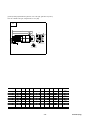
(b) Additional data for motor with providing brake
(i) 0.1 to 1.5 [kW]
Type
GYC□□□DC1-SA-B
Rated output
[kW]
Rated torque
[N • m]
Braking torque
[N • m]
Rated voltage DC
[V]
Attraction time
[ms]
Releasing time
[ms]
Brake input
[W]
Mass (weight)
[kg]
External dimension
101
201
401
0.1
0.2
0.4
0.318
0.637
1.27
0.318
1.27
24
60
80
40
6.5
9
1
1.9
2.6
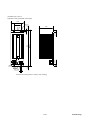
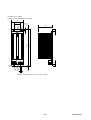
See (1) (b) of 3.3 External dimensions.
2-1
751
0.75
2.39
2.39
102
1
3.18
17
50
80
8.5
4.3
120
30
12
8
152
1.5
4.78
9.8
MHT259a (Engl.)
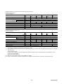
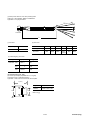
(c) Additional data for motor with providing reduction gear, gear head unit
(i) Motor with gear ratio 1/9
1) 0.1 to 1.5 [kW]
Type
GYN□□□CAG-G09 101
201
401
Motor output
[kW] 0.1
0.2
0.4
Actual reduction gear ratio
1/9
Speed
[r/min] Rated
333.3
Max.
555.5
Rated torque
[N • m] 2.45
4.9
9.8
Max. (breakdown) torque
[N • m] 7.35
14.7
29.4
Direction of motor rotation (*2)
CCW
Backlash (max.) (*4)
[min] 40
30
Mass (weight)
[kg] 0.72
2.1
External dimension
See (1) (e) of 3.3 External dimensions.
751
0.75
102
1
152
1.5
18.1
54.4
25.4
76.4
38.2
116
3.8
7.8
751
48
144
102
G15
1
1/15
200
333.3
39.2
117.6
3.8
7.8
(ii) Motor with gear ratio 1/25 or 1/15
1) 0.1 to 1.5 [kW]
Type
GYN□□□CAG- 101
201
401
G25 or G15 G25
Motor output
[kW] 0.1
0.2
0.4
Actual reduction gear ratio
1/25
Speed
[r/min] Rated
120
Max.
200
Rated torque
[N • m] 6.37
12.7
25.5
Max. (breakdown) torque
[N • m] 19.1
38.2
76.4
Direction of motor rotation (*2)
CCW
Backlash (max.) (*4)
[min] 40
30
Mass (weight)
[kg] 0.72
2.1
External dimension
See (1) (f) of 3.3 External dimensions.
(*1)
(*2)
(*3)
(*4)
0.75
152
1.5
57.8
173.4
15 [μm] for over the rated speed.
Direction of shaft rotation is CCW (counterclockwise), when motor shaft rotates forward (*).
The direction is viewed from a point facing the drive-end of motor.
Max. (breakdown) torque and maximum current values are selected in accordance with the following paired combination of amplifier
and motor types.
Lower value/higher value:
When the same output [kW] rating of amplifier and motor/when amplifier size is one step larger than the motor frame No. size
corresponding with amplifier.
Refer to 2.3 Torque-speed data.
Motor with 3 [min] backlash (max.) can be supplied, on request.
Note : (*) The direction of motor rotation (when viewed from a point facing the drive-end of motor) is designed according to Japanese
standards:
• Forward direction : Counterclockwise rotation (CCW)
• Reverse direction: Clockwise rotation (CW)
2-2
MHT259a (Engl.)
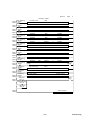
(1) Cubic type motor (0.1 to 5 [kW]) (cont’d)
(a) Basic design
(ii) 2 to 5 [kW]
Type
Rated output
Rated torque
Speed
GYC□□□DC1-SA
[kW]
[N • m]
[r/min] Rated
Max.
Max. (breakdown) torque
[N • m]
-3
2
Moment of inertia of motor rotor (×10 ) J[kg • m ]
Current
[A] Rated
Max.
Winding insulation class
Operation duty type
Degree of enclosure protection
Motor power
Electrical connection
terminals
Encoder detector
Temp. detection
Type of construction (mounting)
Shaft extension, cylindrical
Final color for external non-machined surface
Pulse encoder
Vibration level, peak to peak amplitude
Install location
Ambient climatic conditions
2
Acceleration vibration, acceptable (max.) [m/s ]
Mass (weight)
[kg]
External dimension
202
302
402
502
2
3
4
5
6.37
−
−
−
3000
5000
19.1
−
−
−
0.575
−
−
−
12.6
−
−
−
37.8
−
−
−
F
Continuous
Totally enclosed, IP55 except for shaft sealing
With connectors
Without providing
IMB5, IMV1, IMV3, flange-mounted
With key
Munsell N1.5
16-bit serial encoder
10 [μm] (*1)
For indoors, 1000 [m] and below of site-altitude
Temperature : −10 to +40℃, humidity : 90% RH max. (no condensation)
24.5
8.2
−
−
−
See (1) (a) of 3.3 External dimensions.
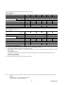
(b) Additional data for motor with providing brake
(ii) 2 to 5 [kW]
Type
GYC□□□DC1-SA-B
Rated output
[kW]
Rated torque
[N • m]
Braking torque
[N • m]
Rated voltage DC
[V]
Attraction time
[ms]
Releasing time
[ms]
Brake input
[W]
Mass (weight)
[kg]
External dimension
202
302
402
2
3
4
3.18
−
−
17
−
−
24
120
−
−
30
−
−
12
−
−
11
See (1) (b) of 3.3 External dimensions.
2-3
502
5
−
−
−
−
−
MHT259a (Engl.)
(c) Additional data for motor with providing reduction gear, gear head unit
(i) Motor with gear ratio 1/9
2) 2 to 5 [kW]
Type
GYN□□□CAG-G09
Motor output
[kW]
Actual reduction gear ratio
Speed
[r/min]
Rated
Max.
Rated torque
[N • m]
Max. (breakdown) torque
[N • m]
Direction of motor rotation (*2)
Backlash (max.) (*4)
[min]
Mass (weight)
[kg]
External dimension
202
302
402
2
3
4
1/9
−
333.3
−
555.5
−
50.9
−
−
152
−
−
CCW
30
−
−
12.2
−
−
See (1) (e) of 3.3 External dimensions.
502
5
202
302
402
2
3
4
1/15
−
200
−
333.3
−
77.4
−
−
232
−
−
CCW
30
−
−
12.2
−
−
See (1) (f) of 3.3 External dimensions.
502
5
−
−
−
−
(ii) Motor with gear ratio 1/25 or 1/15
2) 2 to 5 [kW]
Type
GYN□□□CAG-G15
Motor output
[kW]
Actual reduction gear ratio
Speed
[r/min]
Rated
Max.
Rated torque
[N • m]
Max. (breakdown) torque
[N • m]
Direction of motor rotation (*2)
Backlash (max.) (*4)
[min]
Mass (weight)
[kg]
External dimension
(*1)
(*2)
(*4)
−
−
−
−
15 [μm] for over the rated speed.
Direction of shaft rotation is CCW (counterclockwise), when motor shaft rotates forward.
The direction is viewed from a point facing the drive-end of motor.
Motor with 3 [min] backlash (max.) can be supplied, on request.
2-4
MHT259a (Engl.)
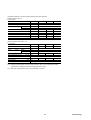
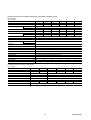
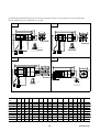
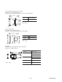
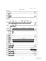
(2) Slim type motor (0.03 to 5 [kW]) for 200 [V] class input voltage of amplifier
(a) Basic design
(i) 0.03 to 0.75 [kW]
Type
GYS□□□DC1S8B, SB or SA
Rated output
[kW]
Rated torque
[N • m]
Speed
[r/min] Rated
Max.
Max. (breakdown) torque (*3)
[N • m]
-3
2
Moment of inertia of motor rotor (×10 ) J[kg • m ]
Current
[A] Rated
Max. (*3)
Winding insulation class
Operation duty type
Degree of enclosure protection
Motor power
Electrical connection
terminals
Encoder detector
Temp. detection
Type of construction (mounting)
Shaft extension, cylindrical
Final color for external non-machined surface
Pulse encoder
Vibration level, peak to peak amplitude
Install location
Ambient climatic conditions
2
Acceleration vibration, acceptable (max.) [m/s ]
Mass (weight)
[kg]
External dimension
300
500
101
201
S8B
SB
SA
0.03
0.05
0.1
0.2
0.095
0.159
0.318
0.637
3000
5000
0.287
0.478
0.955
1.91/2.87
0.00253
0.00341
0.00517
0.0137
0.6
0.93
0.9
1.5
1.8
2.8
2.7
4.5/6.8
B
Continuous
Totally enclosed, IP55 except for shaft sealing
With 0.3 [m] flexible leads and connectors
401
751
0.4
1.27
0.75
2.39
3.82/5.73
0.0249
2.6
7.8/11.8
7.17/10.7
0.0861
4.8
14.4/21.6
Without providing
IMB5, IMV1, IMV3, flange-mounted
Without key (*5)
With key
Munsell N1.5
16-bit serial encoder
5 [μm]
For indoors, 1000 [m] and below of site-altitude
Temperature : −10 to +40°C, humidity : 90% RH max. (no condensation)
49
0.4
0.45
0.55
1.2
1.8
3.4
See (1) (g) of 3.3 External dimensions.
(b) Additional data for motor with providing brake
(i) 0.03 to 0.75 [kW]
Type
GYS□□□DC1S8B-B, SB-B or SA-B
Rated output
[kW]
Rated torque
[N • m]
Braking torque
[N • m]
Rated voltage DC
[V]
Attraction time
[ms]
Releasing time
[ms]
Brake input
[W]
Mass (weight)
[kg]
External dimension
300
500
101
S8B-B
SB-B
0.03
0.05
0.1
0.095
0.159
0.318
−
0.3
−
24
−
35
−
10
−
6.1
−
0.62
0.72
See (1) (h) of 3.3 External dimensions.
2-5
201
SA-B
0.2
0.637
1.27
40
20
7.3
1.7
401
751
0.4
1.27
0.75
2.39
2.45
2.3
60
25
8.5
4.2
MHT259a (Engl.)
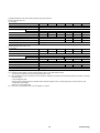
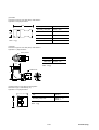
(c) Additional data for motor with providing reduction gear, gear head unit
(i) Motor with gear ratio 1/9
1) 0.03 to 0.75 [kW]
□□□□□□SAG-G09 GYN
300
500
101
Motor output
[kW] 0.03
0.05
0.1
Actual reduction gear ratio
−
1/9
Speed
[r/min] Rated
−
333.3
Max.
−
555.5
Rated torque
[N • m] −
1.23
2.54
Max. (breakdown) torque
[N • m] −
3.68
7.36
Direction of motor rotation (*2)
−
CCW
Backlash (max.) (*4)
[min] −
40
Mass (weight)
[kg] −
0.7
External dimension
See (1) (k) of 3.3 External dimensions.
Type
GRN
.20
0.2
.40
0.4
GYN
751
0.75
4.9
14.7
9.8
29.4
18.1
54.3
30
2.1
3.8
(ii) Motor with gear ratio 1/25 or 1/15
1) 0.03 to 0.75 [kW]
□□□□□□SAG-G25 GYN
300
500
101
Motor output
[kW] 0.03
0.05
0.1
Actual reduction gear ratio
−
1/25
Speed
[r/min] Rated
−
120
Max.
−
200
Rated torque
[N • m] −
3.19
6.37
Max. (breakdown) torque
[N • m] −
9.56
19.1
Direction of motor rotation (*2)
−
CCW
Backlash (max.) (*4)
[min] −
40
Mass (weight)
[kg] −
0.7
External dimension
See (1) (l) of 3.3 External dimensions.
Type
(*2)
(*3)
(*4)
(*5)
GRN
.20
0.2
.40
0.4
GYN
751
0.75
12.7
38.2
25.5
76.4
48
144
30
2.1
3.8
Direction of shaft rotation is CCW (counterclockwise), when motor shaft rotates forward.
The direction is viewed from a point facing the drive-end of motor.
Max. (breakdown) torque and maximum current values are selected in accordance with the following paired combination of amplifier
and motor types.
Lower value/higher value:
When the same output [kW] rating of amplifier and motor/when amplifier size is one step larger than the motor frame No. size
corresponding with amplifier.
Refer to 2.3 Torque-speed data.
Motor with 3 [min] backlash (max.) can be supplied, on request.
When a motor with GYN or GRN type gear-head unit is supplied, the shaft extension of this motor is provided with a key.
2-6
MHT259a (Engl.)
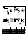
(2) Slim type motor (0.03 to 5 [kW]) for 200 [V] class input voltage of amplifier (cont’d)
(a) Basic design
(ii) 1 to 5 [kW]
Type
Rated output
Rated torque
Speed
GYS□□□DC1-SA
[kW]
[N • m]
[r/min] Rated
Max.
Max. (breakdown) torque (*3)
[N • m]
-3
2
Moment of inertia of motor rotor(×10 ) J[kg • m ]
Current
[A] Rated
Max. (*3)
Winding insulation class
Operation duty type
Degree of enclosure protection
Motor power
Electrical connection
terminals
Encoder detector
Temp. detection
Type of construction (mounting)
Shaft extension, cylindrical
Final color for external non-machined surface
Pulse encoder
Vibration level, peak to peak amplitude
Install location
Ambient climatic conditions
2
Acceleration vibration, acceptable (max.) [m/s ]
Mass (weight)
[kg]
External dimension
102
152
202
302
1
1.5
2
3
3.18
4.78
6.37
9.55
3000
5000
9.55/12.7
14.3/19.1
19.1
28.7
0.174
0.238
0.302
0.873
7.1
9.6
12.6
18.5
21.3/28.4
28.8/38.4
37.8
55.5
F
Continuous
Totally enclosed, IP55 except for shaft sealing
With connectors
402
4
12.7
502
5
15.9
38.2
1.12
24.5
73.5
47.8
1.37
30
90
Without providing
IMB5, IMV1, IMV3, flange-mounted
With key
Munsell N1.5
16-bit serial encoder
10 [μm] (*1)
For indoors, 1000 [m] and below of site-altitude
Temperature : −10 to +40°C, humidity : 90% RH max. (no condensation)
24.5
4.4
5.2
6.3
11
13.5
16
See (1) (g) of 3.3 External dimensions.
(b) Additional data for motor with providing brake
(ii) 1 to 5 [kW]
Type
GYS□□□DC1-SA-B
Rated output
[kW]
Rated torque
[N • m]
Braking torque
[N • m]
Rated voltage DC
[V]
Attraction time
[ms]
Releasing time
[ms]
Brake input
[W]
Mass (weight)
[kg]
External dimension
102
152
202
1
1.5
2
3.18
4.78
6.37
6.86
17
24
60
120
10
30
17
12
5.9
6.8
7.9
See (1) (h) of 3.3 External dimensions.
2-7
302
3
9.55
402
4
12.7
502
5
15.9
13
15.5
18
MHT259a (Engl.)
(c) Additional data for motor with providing reduction gear, gear head unit
(ii) Motor with gear ratio 1/9
2) 1 to 5 [kW]
Type
GYN□□□SAG-G09 102
152
202
Motor output
[kW] 1
1.5
2
Actual reduction gear ratio
1/9
Speed
[r/min] Rated
333.3
Max.
555.5
Rated torque
[N • m] 25.4
38.2
50.9
Max. (breakdown) torque
[N • m] 74.4
114
152
Direction of motor rotation (*2)
CCW
Backlash (max.) (*4)
[min] 30
Mass (weight)
[kg] 7.8
External dimension
See (1) (k) of 3.3 External dimensions.
302
3
402
4
502
5
−
−
−
−
−
−
−
−
−
−
−
−
302
402
502
3
4
5
−
−
−
−
−
−
−
−
−
−
−
−
−
−
(ii) Motor with gear ratio 1/25 or 1/15
2) 1 to 5 [kW]
Type
GYN□□□SAG-G15 102
Motor output
Actual reduction gear ratio
Speed
[r/min]
Rated
Max.
Rated torque
Max. (breakdown) torque
Direction of motor rotation (*2)
Backlash (max.) (*4)
Mass (weight)
External dimension
(*1)
(*2)
(*3)
(*4)
152
202
[kW] 1
1.5
2
1/15
200
333.3
[N • m] 39.2
57.8
77.4
[N • m] 117
173
232
CCW
[min] 30
[kg] 7.8
See (1) (l) of 3.3 External dimensions.
15 [μm] for over the rated speed.
Direction of shaft rotation is CCW (counterclockwise), when motor shaft rotates forward.
The direction is viewed from a point facing the drive-end of motor.
Max. (breakdown) torque and maximum current values are selected in accordance with the following paired combination of amplifier
and motor types.
Lower value/higher value:
When the same output [kW] rating of amplifier and motor/when amplifier size is one step larger than the motor frame No. size
corresponding with amplifier.
Refer to 2.3 Torque-speed data.
Motor with 3 [min] backlash (max.) can be supplied, on request.
2-8
MHT259a (Engl.)
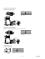
(3) Slim type motor (0.03 to 0.2 [kW]) for 100 [V] class input voltage of amplifier
(a) Basic design
Type
GYS□□□DC1S6B or S8B
Rated output
[kW]
Rated torque
[N • m]
Speed
[r/min] Rated
Max.
Max. (breakdown) torque
[N • m]
-3
2
Moment of inertia of motor rotor(×10 ) J[kg • m ]
Current
[A] Rated
Max.
Winding insulation class
Operation duty type
Degree of enclosure protection
Motor power
Electrical connection
terminals
Encoder detector
Temp. detection
Type of construction (mounting)
Shaft extension, cylindrical
Final color for external non-machined surface
Pulse encoder
Vibration level, peak to peak amplitude
Install location
Ambient climatic conditions
2
Acceleration vibration, acceptable (max.) [m/s ]
Mass (weight)
[kg]
External dimension
300
500
101
201
S8B
S6B
−
0.05
0.1
0.2
−
0.159
0.318
0.637
−
3000
−
5000
−
0.478
0.955
1.91
−
0.00341
0.00517
0.0137
−
0.85
1.5
2.7
−
2.55
4.5
8.1
B
Continuous
Totally enclosed, IP55 except for shaft sealing
With 0.3 [m] flexible leads and connectors
Without providing
IMB5, IMV1, IMV3, flange-mounted
Without key (*5)
Munsell N1.5
16-bit serial encoder
5 [μm]
For indoors, 1000 [m] and below of site-altitude
Temperature : −10 to +40°C, humidity : 90% RH max. (no condensation)
49
−
0.45
0.55
1.2
See (2) (a) of 3.3 External dimensions.
(b) Additional data for motor with providing brake
Type
Rated output
Rated torque
Braking torque
Rated voltage DC
Attraction time
Releasing time
Brake input
Mass (weight)
External dimension
GYS□□□DC1S6B-B or S8B-B
[kW]
[N • m]
[N • m]
[V]
[ms]
[ms]
[W]
[kg]
300
500
101
S8B-B
S6B-B
0.03
0.05
0.1
−
0.159
0.318
−
0.34
−
24
−
35
−
10
−
6.1
−
0.62
0.72
See (2) (b) of 3.3 External dimensions.
201
0.2
0.637
1.27
40
20
7.3
1.7
(c) Additional data for motor with providing reduction gear, gear-head unit
(i) Motor with gear ratio 1/9
□□□□□□SAG-G09 GYN
300
500
101
Rated output
[kW] 0.03
0.05
0.1
Actual reduction gear ratio
1/9
Speed
[r/min] Rated
−
333.3
Max.
−
555.5
Rated torque
[N • m] −
1.23
2.54
Max. (breakdown) torque
[N • m] −
3.68
7.36
Direction of motor rotation (*2)
−
CCW
Backlash (max.) (*4)
[N • m] −
40
Mass (weight)
[kg] −
0.7
External dimension
See (1) (k) of 3.3 External dimensions.
Type
2-9
GRN
.20
0.2
4.9
14.7
30
2.1
MHT259a (Engl.)
(c) Additional data for motor with providing reduction gear, gear-head unit (cont’d)
(ii) Motor with gear ratio 1/25
□□□□□□SAG-G25 GYN
300
500
101
Rated output
[kW] 0.03
0.05
0.1
Actual reduction gear ratio
1/25
Speed
[r/min] Rated
−
120
Max.
−
200
Rated torque
[N • m] −
3.19
6.37
Max. (breakdown) torque
[N • m] −
9.56
19.1
Direction of motor rotation (*2)
−
CCW
Backlash (max.) (*4)
[min] −
40
Mass (weight)
[kg] −
0.7
External dimension
See (1) (l) of 3.3 External dimensions.
Type
(*2)
(*4)
(*5)
GRN
.20
0.2
12.7
38.2
30
2.1
Direction of shaft rotation is CCW (counterclockwise), when motor shaft rotates forward.
The direction is viewed from a point facing the drive-end of motor.
Motor with 3 [min] backlash (max.) can be supplied, on request.
When a motor with GYN or GRN type gear-head unit is supplied, the shaft extension of this motor is provided with a key.
2-10
MHT259a (Engl.)
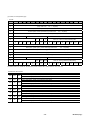
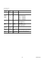
2.2 Amplifier
(1) Basic specification for 200 [V] input voltage of amplifier
(a) 0.03 to 0.75 [kW]
Amplifier type
RYS□□□S3-LPS
Applicable motor output (*1)
[kW]
Input
Phase, freq.
Voltage
Control
System
data
Carrier freq.
[kHz]
Feedback
Speed
Loading
control
Supply volt.
accuracy
Amb. temp.
Speed range
Freq. response
Load inertia. max.
Overload capability
Function
Ambient
condition
Braking
Protection
Display, setting
Install location
Temp., humidity
Vibration / shock
Others
Mass (weight)
(*1)
(*2)
[kg]
300
500
101
201
401
751
0.03
0.05
0.1
0.2
0.4
0.75
3-phase for power supply, single-phase for control, 50/60 [Hz]
200/200-220-230 [V], +10 to −15%
Sinusoidal wave PWM current control (all digital)
10
16 bit serial encoder (one-rotation resolution 16 bit, multiple-rotation 16 bit)
for 0 to 100% deviation
±1 [r/min]
max.
For −10 to +10% fluctuation
±0.2% max. for 25°C±10% variation (at analog volt. input)
1 : 5000 (at rated load)
600 [Hz] (at JL = JM (*2) )
100 times of the motor rotor inertia, permissible
300% for approx. 3 [s]
300% for approx. 3 [s], 450% for approx.
1.5 [s]
Regenerating, dynamic with external braking resistor
OC (output overcurrent), OS (overspeed), LV (low voltage, undervoltage),
HV (high voltage, overvoltage), Et (encoder trouble), Ct (circuit trouble, amplifier trouble),
dE (data error, memory error), CE (combination error), rH2 (resistor heat 2),
EC (encoder communication error), CtE (cont (control signal) error),
OL (motor overload), rH (resistor heat, braking (OB) resistor overheat),
OF (over flow, deviation excessive), AH (amp. heat, amplifier overheat),
EH (encoder heat, encoder overheat), AL (absolute data lost),
AF (absolute data over flow), Fb (fuse blown)
CHARGE (red), 7-segment LED with 5 digit and 4 operation keys
For indoors, 1000 [m] and below of site-altitude, under clean atmosphere,
no explosive hazardous gas and vapour is existing.
In the case of compliance with the European standard :
Pollution degree = 2, Over voltage category = Ⅱ
−10 to +55°C, 90% RH max. (no condensation)
2
2
4.9 [m/s ] / 19.6 [m/s ] acceleration, acceptable (max.)
DC reactor terminals (P1, P+) for harmonics suppression.
UL/cUL (compliance with UL508), European standards (compliance with EN50178)
0.9
1.2
1.5
Use amplifier and motor as a specified pair of types.
Fox GYC type motor with 0.1 to 1.5 [kW] or GYS type motor with 0.2 to 1.5 [kW] rated output :
If the RYS401 (0.4 [kW]) type amplifier and GYS201 (0.2 [kW]) motor (which is a step smaller than the optimum combination) is
combined as a pair, allowable max. (breakdown) torque of 0.2 [kW] motor can be obtained as 450% (in the case of the max. torque of
the motor is 450%) of the rated torque.
Furthermore, in this case, other data are as follows :
• The moment of load inertia after conversion into motor shaft extension is at most 30 times the moment of inertia of motor rotor.
• Acceleration/deceleration time up to rated speed is 2 [ms] or more.
• The motor shaft extension is directly mechanically connected and is subjected to no external radial or thrust force.
Moment of inertia
JL : Moment of load inertia after conversion into motor shaft extension
JM : Moment of inertia of motor rotor
2-11
MHT259a (Engl.)
(b) 1 to 5 [kW]
Amplifier type
RYS□□□S3-LPS
Applicable motor output (*1)
[kW]
Input
Phase, freq.
Voltage
Control
System
data
Carrier freq.
[kHz]
Feedback
Speed
Loading
control
Supply volt.
accuracy
Amb. temp.
Speed range
Freq. response
Load inertia. max.
Overload capability
Function
Ambient
condition
Braking
Protection
Display, setting
Install location
Temp., humidity
Vibration / shock
Others
Mass (weight)
(*1)
(*2)
[kg]
102
152
202
302
402
502
1
1.5
2
3
4
5
3-phase for power supply, single-phase for control, 50/60 [Hz]
200/200-220-230 [V], +10 to −15%
Sinusoidal wave PWM current control (all digital)
10
5
16 bit serial encoder (one-rotation resolution 16 bit, multiple-rotation 16 bit)
for 0 to 100% deviation
±1 [r/min]
max.
For −10 to +10% fluctuation
±0.2% max. for 25°C±10% variation (at analog volt. input)
1 : 5000 (at rated load)
600 [Hz] (at JL = JM (*2) )
100 times of the motor rotor inertia, permissible
300% for approx. 3 [s],
300% for approx. 3 [s]
450% for approx. 1.5 [s]
Regenerating, dynamic with external braking resistor
OC (output overcurrent), OS (overspeed), LV (low voltage, undervoltage),
HV (high voltage, overvoltage), Et (encoder trouble), Ct (circuit trouble, amplifier trouble),
dE (data error, memory error), CE (combination error), rH2 (resistor heat 2),
EC (encoder communication error), CtE (cont (control signal) error),
OL (motor overload), rH (resistor heat, braking (OB) resistor overheat),
OF (over flow, deviation excessive), AH (amp. heat, amplifier overheat),
EH (encoder heat, encoder overheat), AL (absolute data lost),
AF (absolute data over flow) , Fb (fuse blown) for 2 [kW] and more
CHARGE (red), 7-segment LED with 5 digit and 4 operation keys
For indoors, 1000 [m] and below of site-altitude, under clean atmosphere,
no explosive hazardous gas and vapour is existing.
In the case of compliance with the European standard :
Pollution degree = 2, Over voltage category = Ⅱ
−10 to +55°C, 90% RH max. (no condensation)
2
2
4.9 [m/s ] / 19.6 [m/s ] acceleration, acceptable (max.)
DC reactor terminals (P1, P+) for harmonics suppression.
UL/cUL (compliance with UL508), European standards (compliance with EN50178)
2
4.6
4.7
5.2
Use amplifier and motor as a specified pair of types.
Fox GYC type motor with 0.1 to 1.5 [kW] or GYS type motor with 0.2 to 1.5 [kW] rated output :
If the RYS401 (0.4 [kW]) type amplifier and GYS201 (0.2 [kW]) motor (which is a step smaller than the optimum combination) is
combined as a pair, allowable max. (breakdown) torque of 0.2 [kW] motor can be obtained as 450% (in the case of the max. torque of
the motor is 450%) of the rated torque.
Furthermore, in this case, other data are as follows :
• The moment of load inertia after conversion into motor shaft extension is at most 30 times the moment of inertia of motor rotor.
• Acceleration/deceleration time up to rated speed is 2 [ms] or more.
• The motor shaft extension is directly mechanically connected and is subjected to no external radial or thrust force.
Moment of inertia
JL : Moment of load inertia after conversion into motor shaft extension
JM : Moment of inertia of motor rotor
2-12
MHT259a (Engl.)
(2) Basic specification for 100 [V] class input voltage of amplifier
0.05 to 0.2 [kW]
Amplifier type
RYS□□□S3-LPS6
Applicable motor output (*1)
[kW]
Input
Phase, freq.
Voltage
Control
System
data
Carrier freq.
[kHz]
Feedback
Speed
Loading
control
Supply volt.
accuracy
Amb. temp.
Speed range
Freq. response
Load inertia. max.
Overload capability
Function
Braking
Protection
Ambient
condition
Display, setting
Install location
Temp., humidity
Vibration / shock
Others
Mass (weight)
(*1)
(*2)
[kg]
500
101
201
0.05
0.1
0.2
Single-phase for power supply, for control, 50/60 [Hz]
100 to 115 [V], +10 to −15%
Sinusoidal wave PWM current control (all digital)
10
16-bit serial encoder (one-rotation resolution 16 bit, multiple-rotation 16 bit)
for 0 to 100% deviation
±1 [r/min]
max.
For −10 to +10% fluctuation
±0.2% max. for 25°C±10% variation (at analog volt. input)
1 : 5000 (at rated load)
600 [Hz] (at JL = JM (*2) )
100 times of the motor rotor inertia, permissible
300% for approx. 3 [s]
Regenerating, dynamic with external braking resistor
OC (output overcurrent), OS (overspeed), LV (low voltage, undervoltage),
HV (high voltage, overvoltage), Et (encoder trouble), Ct (circuit trouble, amplifier trouble),
dE (data error, memory error), CE (combination error), rH2 (resistor heat 2),
EC (encoder communication error), CtE (cont (control signal) error),
OL (motor overload), rH (resistor heat, braking (OB) resistor overheat),
OF (over flow, deviation excessive), AH (amp. heat, amplifier overheat),
EH (encoder heat, encoder overheat), AL (absolute data lost),
AF (absolute data over flow)
CHARGE (red), 7-segment LED with 5 digit and 4 operation keys
For indoors, 1000 [m] and below of site-altitude, under clean atmosphere,
no explosive hazardous gas and vapour is existing.
In the case of compliance with the European standard :
Pollution degree = 2, Over voltage category = Ⅱ
−10 to +55°C, 90% RH max. (no condensation)
2
2
4.9 [m/s ] / 19.6 [m/s ] acceleration, acceptable (max.)
DC reactor terminals (P1, P+) for harmonics suppression.
UL/cUL (compliance with UL508), European standards (compliance with EN50178)
0.9
1.2
Use amplifier and motor as a specified pair of types:For example, “RYS500” type amplifier can be combined with the acceptable
“GYS500” type motor only.
Moment of inertia
JL : Moment of load inertia after conversion into motor shaft extension
JM : Moment of inertia of motor rotor
2-13
MHT259a (Engl.)
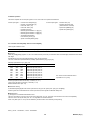
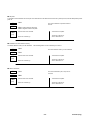
(3) Functional specification : Basic design, RYS□□□
□□□S3-LPS
type amplifier
□□□
Signal name
Function
Host interface (I/F)
Pulse train
Input
Form
DI/DO (+24 [V] DC)
Freq. 500 [kHz] max. (differential input)
(1) Command pulse and code, (2) Forward and reverse pulse,
(3) Two 90° phase-different signal
Freq. 500 [kHz] max. (differential output)
Two 90° phase-different signal
16 to 16384 [pulse/rev] (in 1 step)
+10 ±0.4 [V] (output current 30 [mA] max.)
±10 [V] (20 kΩ input impedance)
For analog-meter (two/one-way deflection), (1) Speed command,
(2) Speed feedback, (3) Torque command, (4) Position deviation
+24 [V] DC, 300 [mA] (supplied from external)
+24 [V] DC, 10 [mA] (one-point) source input
Signal assign terminals of control input
+30 [V] DC, 50 [mA] max. sink output
Signal assign terminals of control output
Input terminals of backup power supply from external to encoder
Freq.
dividing
output
Output
Form
Pulse
Speed
Power supply
command
Input
Monitor output 1/2
Power supply for I/F
Control input
OUT output
External backup
Control function
Position control
Origin setting
Position data
Position command, max.
Others
Terminal
symbol
−
CA, *CA
CB, *CB
FA, *FA
FB, *FB
FZ, *FZ
P10, M5
NREF
MON1
MON2
P24, M24
CONT1 to
CONT13
OUT1 to
OUT10
BAT+, BAT−
・Auto start (address specify, sequential starting, immediately positioning)
・Manual run (analog voltage, multistep speed, interrupt positioning)
・Pulse train input, origin return (4 pattern)
LS (origin limit switch) and Z-phase, position preset
99-point (position, speed, timer, M-code and statuses)
±79,999,999 (x unit q'ty)
Override, brake timing output, etc.
(4) Functional specification : SX bus type design, RYS□□□
□□□S3-LSS
type amplifier
□□□
Signal name
Function
Host interface (I/F)
Pulse train
Input
Form
SX bus (IQ area, 16 word)
Freq. 500 [kHz] max. (differential input)
(1) Command pulse and code, (2) Forward and reverse pulse,
(3) Two 90° phase-different signal
5 [V] DC, 200 [mA] (max.)
Power supply
Freq.
dividing
output
Output
Form
Pulse
Monitor output 1/2
Power supply for I/F
Control input
OUT output
External backup
Control function
Position control
Origin setting
Position data
Position command, max.
Others
Freq. 500 [kHz] max. (differential output)
Two 90° phase-different signal
16 to 16384 [pulse/rev] (in 1 step)
For analog-meter (two/one-way deflection), (1) Speed command,
(2) Speed feedback, (3) Torque command, (4) Position deviation
+24 [V] DC, 300 [mA] (supplied from external)
+24 [V] DC, 10 [mA] (one-point) source input
External control input terminals
+30 [V] DC, 50 [mA] max. sink output
External control output terminals
Input terminals of backup power supply from external to encoder
Terminal
symbol
(IN, OUT)
CA, *CA
CB, *CB
P5
FA, *FA
FB, *FB
FZ, *FZ
MON1
MON2
P24, M24
CONT1 to
CONT5
OUT1 and
OUT2
BAT+, BAT−
・Auto start (address specify, sequential starting, immediately positioning)
・Manual run (multistep speed, interrupt positioning), pulse train input, origin return (4 pattern)
LS (origin limit switch) and Z-phase, position preset
99-point (position, speed, timer, M-code and statuses)
±79,999,999 (x unit q'ty)
Override, brake timing output, etc.
2-14
MHT259a (Engl.)
(5) Functional specification : T-link type design, RYS□□□
□□□S3-LTS
type amplifier
□□□
Signal name
Function
Host interface (I/F)
Pulse train
Input
Form
T-link (WB area, 8 word)
Freq. 500 [kHz] max. (differential input)
(1) Command pulse and code, (2) Forward and reverse pulse,
(3) Two 90° phase-different signal
Power supply
Output
Form
Pulse
Monitor output 1/2
5 [V] DC, 200 [mA] (max.)
Freq. 200 [kHz] max. (open collector)
Two 90° phase-different signal
16 to 16384 [pulse/rev] (in 1 step)
For analog-meter (two/one-way deflection), (1) Speed command,
(2) Speed feedback, (3) Torque command, (4) Position deviation
+24 [V] DC, 300 [mA] (supplied from external)
+24 [V] DC, 10 [mA] (one-point) source input
External control input terminals
+30 [V] DC, 50 [mA] max. sink output
External control output terminals
Input terminals of backup power supply from external to encoder
Freq.
dividing
output
Power supply for I/F
Control input
OUT output
External backup
Control function
Position control
Origin setting
Position data
Position command, max.
Others
Terminal
symbol
T2, T1, SD
CA, *CA
CB, *CB
P5
FA, FB, FZ
MON1
MON2
P24, M24
CONT1 to
CONT8
OUT1 to
OUT4
BAT+, BAT−
Auto start (address specify, sequential starting, immediately positioning)
Manual run (analog voltage, multistep speed, interrupt positioning), pulse train input, origin return (4
pattern)
LS (origin limit switch) and Z-phase, position preset
99-point (position, speed, timer, M-code and statuses)
±79,999,999 (x unit q'ty)
Override, brake timing output, etc.
(6) Functional specification : General-purpose communication (RS485 interface) type design, RYS□□□
□□□S3-LRS
type amplifier
□□□
Signal name
Function
Host interface (I/F)
Pulse train
Input
Form
RS485 (4-wire half-duplex/31 stations, max.)
Freq. 500 [kHz] max. (differential input)
(1) Command pulse and code, (2) Forward and reverse pulse,
(3) Two 90° phase-different signal
Power supply
Output
Form
Pulse
Monitor output 1/2
5 [V] DC, 200 [mA] (max.)
Freq. 200 [kHz] max. (differential output)
Two 90° phase-different signal
16 to 16384 [pulse/rev] (in 1 step)
For analog-meter (two/one-way deflection), (1) Speed command,
(2) Speed feedback, (3) Torque command, (4) Position deviation
+24 [V] DC, 300 [mA] (supplied from external)
+24 [V] DC, 10 [mA] (one-point) source input
External control input terminals
+30 [V] DC, 50 [mA] max. sink output
External control output terminals
Input terminals of backup power supply from external to encoder
Freq.
dividing
output
Power supply for I/F
Control input
OUT output
External backup
Control function
Position control
Origin setting
Position data
Position command, max.
Others
Terminal
symbol
−
CA, *CA
CB, *CB
P5
FA, FB, FZ
MON1
MON2
P24, M24
CONT1 to
CONT8
OUT1 to
OUT4
BAT+, BAT−
Auto start (address specify, immediately positioning)
Manual run (multistep speed, interrupt positioning), pulse train input, origin return (4 pattern)
LS (origin limit switch) and Z-phase, position preset
99-point (position, speed, timer, M-code and statuses)
±79,999,999 (x unit q'ty)
Override, brake timing output, etc.
2-15
MHT259a (Engl.)
(7) Optional cables, connection kits, battery and external braking resistors
See (3) of 4.1 Amplifier, motor and optional devices layout, and 10.8 Optional cables, connector kits, battery and external braking resistors.
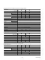
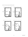
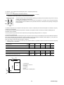
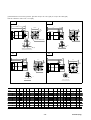
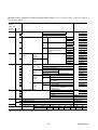
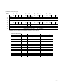
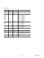
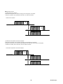
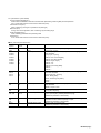
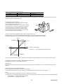
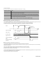
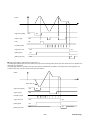
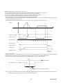
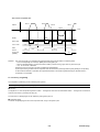
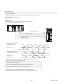
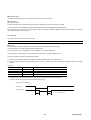
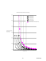
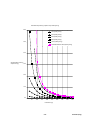
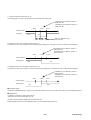
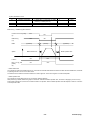
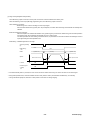
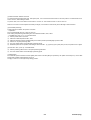
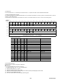
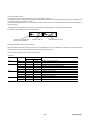
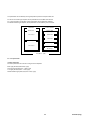
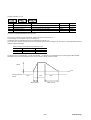
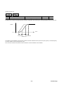
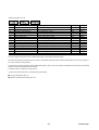
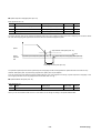
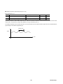
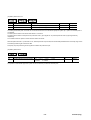
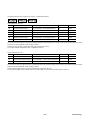
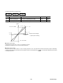
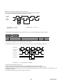
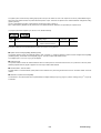
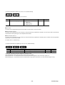
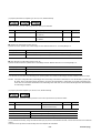
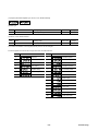
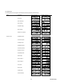
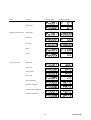
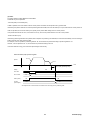
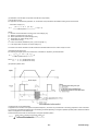
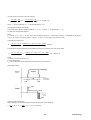
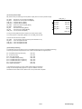
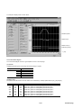
2.3 Torque-speed data
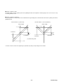
Shown below are the torque characteristic with each motor and amplifier combination.
(a) Within the range of “(A) Acceleration/deceleration area 1” and “(B) Acceleration/deceleration area 2” are used for accel./decel. (*) the
motor.
(i) (A) Acceleration/deceleration area 1 : Output torque is available at accel./decel. In case of the same output [kW] rating of the amplifier
and motor combination.
(ii) (B) Acceleration/deceleration area 2 : Output torque is available at accel./decel. When the amplifier size is one step larger than the
motor frame No. size corresponding with the amplifier. See (3) (d) of 10.3 Combination error.
(iii) In the case of (A) and (B), a torque higher than rated cannot be outputted continuously.
(b) Within the range of “(C) Continuous operation area”, the motor can continuously be operated (at rated speed or lower). Above the
rated speed, the rated torque cannot be outputted continuously.
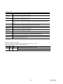
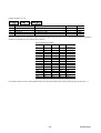
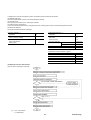
(c) The overload detecting time (guidepost) is as follows.
Output torque
[%]
Overload detecting
time
approx. [s]
100 (rated torque)
Continuous operation is
acceptable.
125
35
150
18
200
9
300
3
450
1.5
Before tripping by overload, an early warning signal can be outputted. See 5.6.6 Overload early warning.
Note : (*) Accel. : Accelerating or acceleration
Decel. : Decelerating or deceleration
2-16
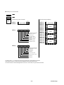
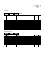
MHT259a (Engl.)
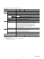
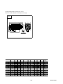
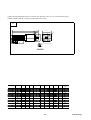
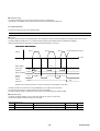
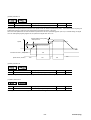
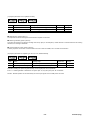
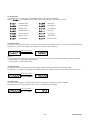
(1) GYC motor, cubic type, for 200 [V] class input voltage of amplifier
・GYC101DC1−SA(0.1[kW])
・GYC201DC1−SA(0.2 [kW])
1.6
4.0
1.43
3.5
1.4
(B)
1.2
1.0
0.955
Torque
[N・m] 0.8
3.0
2.87
2.5
(B)
Torque
[N・m] 2.0
(A)
0.6
1.91
1.5
0.4
1.0
0.318
0.2
0.637
0.5
(C)
0
1000 2000 3000
Speed [r/min]
(A)
(C)
4000
5000
0
・GYC401DC1−SA(0.4[kW])
8.0
1000 2000 3000
Speed [r/min]
4000
5000
・GYC751DC1−SA(0.75[kW])
16.0
14.0
7.0
12.0
5.73
6.0
10.7
(B)
5.0
Torque
[N・m] 4.0
10.0
(A)
3.0
(B)
Torque
[N・m] 8.0
3.82
7.17
6.0
(A)
4.0
2.0
2.39
1.27
2.0
1.0
(C)
0
1000 2000 3000
Speed [r/min]
(C)
4000
0
5000
1000 2000 3000
Speed [r/min]
4000
5000
(A) Acceleration/deceleration area 1
(B) Acceleration/deceleration area 2
(C) Continuous operation area
2-17
MHT259a (Engl.)
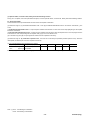
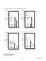
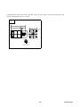
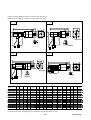
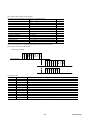
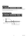
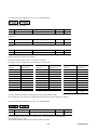
(1) GYC motor, cubic type, for 200 [V] class input voltage of amplifier (cont’d)
・GYC102DC1−SA(1[kW])
16.0
・GYC152DC1−SA(1.5[kW])
40.0
14.3
14.0
35.0
12.0
(B)
30.0
10.0
9.55
25.0
Torque
[N・m] 8.0
Torque
[N・m]20.0
(A)
21.5
(B)
6.0
15.0
3.18
4.0
2.0
(A)
10.0
4.78
5.0
(C)
14.3
(C)
0
1000 2000 3000
Speed [r/min]
4000
5000
0
1000 2000 3000
Speed [r/min]
4000
5000
・GYC202DC1−SA(2[kW])
40.0
35.0
30.0
25.0
Torque
[N・m]20.0
28.7
(B)
19.1
15.0
(A)
10.0
6.37
5.0
(C)
0
1000 2000 3000
Speed [r/min]
4000
5000
(A) Acceleration/deceleration area 1
(B) Acceleration/deceleration area 2
(C) Continuous operation area
2-18
MHT259a (Engl.)
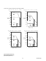
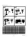
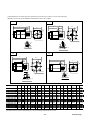
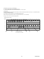
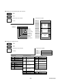
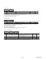
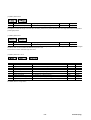
(2) GYS motor, slim type, for 200 [V] class input voltage of amplifier
・GYS500DC1−S8B(0.05[kW]) ・GYS101DC1−SB(0.1[kW])
0.8
1.6
0.7
1.4
0.6
1.2
0.5
0.478
Torque
[N・m] 0.4
1.0
(A)
0.955
Torque
[N・m] 0.8
0.3
(A)
0.6
0.2
0.159
0.4
0.318
(C)
0.1
(C)
0.2
0
1000 2000 3000
Speed [r/min]
4000
5000
・GYS201DC1−SA(0.2[kW])
0
8.0
3.5
7.0
2.87
2.5
(B)
Torque
[N・m] 2.0
1.5
(B)
5.0
Torque
[N・m] 4.0
3.82
(A)
3.0
(A)
1.0
5000
5.73
6.0
1.91
4000
・GYS401DC1−SA(0.4[kW])
4.0
3.0
1000 2000 3000
Speed [r/min]
2.0
0.637
1.27
1.0
0.5
(C)
(C)
0
1000 2000 3000
Speed [r/min]
4000
5000
0
2-19
1000 2000 3000
Speed [r/min]
4000
5000
MHT259a (Engl.)
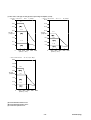
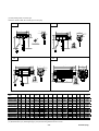
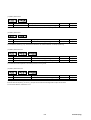
(2) GYS motor, slim type, for 200 [V] class input voltage of amplifier (cont’d)
・GYS751DC1−SA(0.75[kW])
16.0
・GYS102DC1−SA(1[kW])
16.0
14.3
14.0
14.0
12.0
12.0
(B)
10.7
9.55
10.0
10.0
(B)
Torque
[N・m] 8.0
7.17
(A)
6.0
4.0
Torque
[N・m] 8.0
(A)
6.0
4.0
3.18
2.0
(C)
2.39
2.0
(C)
0
0
1000 2000 3000 4000 5000
Speed [r/min]
・GYS152DC1−SA(1.5[kW])
40.0
・GYS202DC1−SA(2[kW])
40.0
35.0
35.0
30.0
30.0
25.0
25.0
21.5
Torque
[N・m] 20.0
1000 2000 3000 4000 5000
Speed [r/min]
28.7
Torque
[N・m] 20.0
(B)
19.1
(B)
14.3
15.0
(A)
10.0
15.0
(A)
10.0
6.37
4.78
5.0
5.0
(C)
(C)
0
0
1000 2000 3000 4000 5000
Speed [r/min]
1000 2000 3000 4000 5000
Speed [r/min]
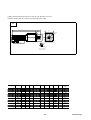
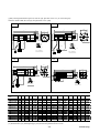
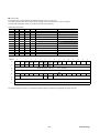
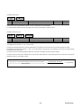
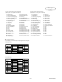
(A) Acceleration/deceleration area 1
(B) Acceleration/deceleration area 2
(C) Continuous operation area
2-20
MHT259a (Engl.)
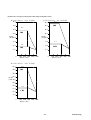
(2) GYS motor, slim type, for 200 [V] class input voltage of amplifier (cont’d)
・GYS302DC1−SA(3[kW])
40.0
・GYS402DC1−SA(4[kW])
38.2
40.0
(A)
35.0
35.0
28.7
30.0
25.0
30.0
(A)
25.0
Torque
[N・m]20.0
Torque
[N・m]20.0
15.0
15.0
12.7
9.55
10.0
10.0
(C)
(C)
5.0
5.0
0
1000 2000 3000 4000 5000
Speed [r/min]
0
1000 2000 3000 4000 5000
Speed [r/min]
・GYS502DC1−SA(5[kW])
50.0
47.8
45.0
(A)
40.0
35.0
Torque
[N・m] 30.0
25.0
20.0
15.9
15.0
(C)
10.0
5.0
0
1000 2000 3000 4000 5000
Speed [r/min]
2-21
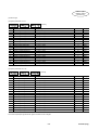
MHT259a (Engl.)
(3) GYS motor, slim type, for 100 [V] class input voltage of amplifier
・GYS500DC1−S8B(0.05[kW])
・GYS101DC1−S6B(0.1[kW])
0.8
1.6
0.7
1.4
0.6
1.2
0.5
1.0
0.478
Torque
[N・m] 0.4
0.955
Torque
[N・m] 0.8
(A)
0.3
(A)
0.6
0.2
0.4
0.159
(C)
0.1
0
1000 2000 3000
Speed [r/min]
0.318
(C)
0.2
4000
5000
0
1000 2000 3000
Speed [r/min]
4000
5000
・GYS201DC1−S6B(0.2[kW])
4.0
3.5
3.0
2.5
Torque
[N・m] 2.0
1.91
(A)
1.5
1.0
0.637
0.5
(C)
0
1000 2000 3000
Speed [r/min]
4000
5000
2-22
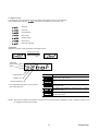
MHT259a (Engl.)
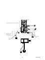
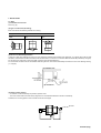
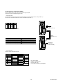
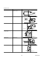
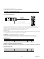
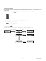
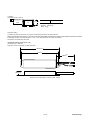
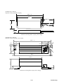
3. INSTALLATION
3.1 Motor
(1) Installation environment
See 3.2 (1) (a)
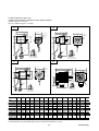
(2) Type of construction (mounting)
Each motor allows the following methods of mounting.
Flange-mounted
IMB5
IMV1
IMV3
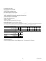
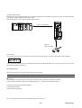
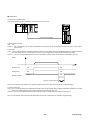
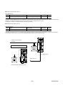
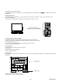
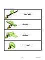
(3) No-oil or no-water-drop protection
In case oil or water drop splashes the motor, the motor should be protected with a suitable cover (example : “a” of figure), which will not close
ventilation, and the motor should be mounted so that the terminal box, connector or connection cable should also be protected (“b” of figure).
Do not allow oil or water drop to enter the inside of motor through the shaft extension.
For mechanical connection with an oil-lubricated reduction gear unit, its oil level should always be lower than in the motor bearing-housing
(“c” of figure).
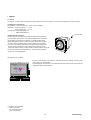
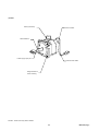
(4) Rotary encoder detector
・ An encoder is used for detecting the position, speed of motor.
・ The motor and encoder have been factory-aligned in the circumferential direction at the time of assembly.
Therefore, the mounting position of the encoder should not be changed.
Encoder
3-1
MHT259a (Engl.)
DO NOT DISASSEMBLE
Do not disassemble the motor unit. There is a risk that the machine can be broken due to abnormal operation.
CAUTION
Never give shocks to the encoder, motor and shaft extension, for example by hitting them with a hammer etc.
In addition, be careful not to apply a load to the encoder during installation.
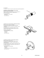
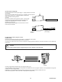
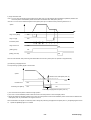
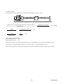
(5) Mechanical coupling
(a) Motor with flexible coupling
(i) Provide a reference mark on the peripheral surface of the
coupling.
(ii) Connect both halves of the coupling with a single-bolt, in order to
allow them to rotate together.
(iii) Attach a dial gauge securely to one half of the coupling so that
its feeler rests lightly on the other half.
(iv) Bring the reference mark to the top of the coupling and, then,
measure dimension “g” with a thickness gauge and dimension “h”
with a dial gauge.
(v) Turn the coupling and carry out the measurements described in (iv)
above at 90°intervals until the reference mark appears at the top
again.
(vi) Conduct adjustments so that the difference between the
maximum and the minimum measurements is held to within
0.03mm. Be sure to bolt the motor and driven machine to the base
prior to marking adjustments.
If a coupling is too small to allow a dial gauge to be attached to it,
attach a stretch (rectangular steel bar) to one half of the coupling
and measure the clearance value of the stretch and the surface of
the other half of the coupling.
(b) Motor for extemal gear drive
If a gear drive is used, the shafts of both machines should be
exactly parallel, to avoid subjecting the gear teeth to an excessive
load at the contact points.
(c) Motor for timing belt connection
When using a timing belt, obtain necessary data from the belt
supplier, and contact Fuji.
(6) Power supply to motor
CAUTION
Do not connect commercial power supply to the motor terminals.
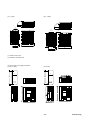
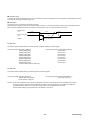
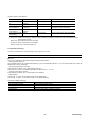
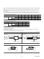
(7) Dimensional tolerances
Tolerances of motor at the time of shipment from the factory are as follows.
The maximum and minimum values throgh one slow revolution of the shaft are then read on the indicator.
The difference between the readings will not exceed the values given in the following table.
(a) Shaft extension run-out
The probe of the indicator is attached to the shaft midway along its length.
(b) Concentricity of spigot and the shaft for flange-mounted motor
The indicator is fitted rigidly on the shaft extension.
3-2
MHT259a (Engl.)
(c) Perpendicularity of mounting face of flange to shaft for flange-mounted motor
The indicator is fitted rigidly on the shaft extension.
[unit : mm]
(a)
(b)
(c)
Flange-mounted
Flange-mounted
Flange-mounted
0.02
0.06
0.08
Motor
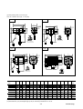
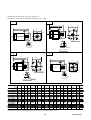
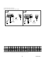
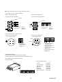
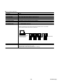
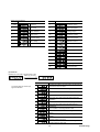
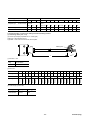
(8) Mounting instruction of GYN and GRN type gear-head unit
(a) Greasing to the shaft extension
Apply grease lightly to the output shaft extension of the motor, before
mounting a GYC or GYS motor to gear-head unit.
Lightly greased
(b) Preparation for mounting
Remove the rubber cap from a deep point of the flange face of the
gear-head unit.
Rubber cap
Hexagonal socket headed
lock screw
Gear-head unit
(c) Match the position of the key of the gear-head input-shaft with
the position of the rubber cap hole.
Loosen the “hexagonal socket headed lock screw”, which is located
in the rubber cap hole. The hexagonal socket headed lock screw is
positioned on the gear-head input-shaft.
3-3
MHT259a (Engl.)
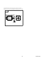
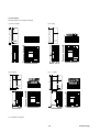
(d) Mounting of motor
lnsert the motor shaft extension with the key
position matched with the gear-head input-shaft.
Fasten the motor’s flange face to the gear-head unit’s
flange face by the screws provided for the gear-head
unit.
(e) Screw sizes
Motor type
Gear-head type
GYS
GYN□□□SAG GRN□□□
SAG
500
101
.20
.40
(i) Screws for fastening of flanges
Screw size [mm] M4×12
Screw q’ty
4
Tightening torque 1.8 ±0.21
[N・m]
(ii) Lock screws
Screw size [mm] M4×4
Tightening torque 1.8 ±0.21
[N・m]
GYC
GYN□□□SAG GYN□□□CAG
751
101
201
401
751
M5×12
M4×12
M5×12
3.5 ±0.42
1.8 ±0.21
3.5 ±0.42
Tighten the “hexagonal socket headed lock screw” after fastening of flange faces.
Fit rubber cap in the original position.
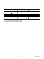
3.2 Amplifier
(1) Installation environment
(a) Ambient climatic conditions
Ambient conditions
In transportation and storage
(*1)
Control rooms and equipment rooms
(*1)
Install location (*2)
Amplifier
Motor
Temperature
−20 to +80℃
−10 to +70℃
Humidity
90% RH max.
Air pressure
86 to 106 [kPa]
Temperature
−10 to +55℃
Humidity
90% RH max.
Air pressure
86 to 106 [kPa]
−10 to +40℃
For indoors
(*1) Free from condensation, no condensation, no formation of ice
(*2) Site-altitude should be 1000 [m] and below.
(b) Avoid use under the following conditions.
(i) Location near oil, steam or corrosive gas
(ii) Location where strong electric or magnetic field exists
(iii) Accommodation in the same panel together with high voltage (2 [kV] or higher) equipment
(iv) Sharing of the same power supply with the equipment which generates large noise.
(v) In vacuum
(vi) In explosive atmosphere
(vii) Under acceleration vibration
3-4
MHT259a (Engl.)
C
I
D
L
A
F
(2) Mounting
(a) Amplifier should be mounted upright so that character
“FALDIC” on the front panel can be seen horizontal.
RYS401S3-VVS
MODE
ESC
K80791543
SHIFT
ENT
CHARGE
L1
L2
L3
DB
P1
P+
N
U
V
W
(b) Avoid overheating of the amplifier
When accommodating multiple amplifiers in the same panel, they should be installed side by side with the sufficient clearance distances
below secured.
(a)
(f)
(f)
C
I
D
L
A
F
C
I
D
L
A
F
RYS201S3-VVS
MODE
ESC
(c)
K80791234
(a)
SHIFT
ENT
RYS201S3-VVS
MODE
ESC
(d)
CHARGE
K80791234
SHIFT
ENT
CHARGE
L1
L1
L2
L2
L3
L3
DB
DB
P1
P1
P+
P+
N
N
U
U
V
V
W
W
(b)
[unit : mm (min.)]
(a)
Upper and
front
(b)
Lower
(c)
Left and right
(d)
Between amplifiers
50
40
10
(i) 5
(ii) If the clearance is 4.9 [mm] and below, operation duty type of amplifier is
reduced to 80%ED (*), instead of continuous duty.
(f) Fan mounting
3-5
MHT259a (Engl.)
(*) 80%ED : Cyclic duration factor operating duty is 80% : Intermittent periodic duty
The factor is defined as
N (operation under rated conditions)
×100 [%]
N (operation under rated conditions) + R (at rest and de-energized)
Intermittent periodic duty involve alternating operating and loading times and pauses during which a motor (or
amplifier) is at a standstill (or de-energized).
The loading and standstill times of one cycle, which has a duration of 10 minutes, are so short that the steadystate temperature cannot be attained. The cycle duration factor is the ratio between the operating or loading time
and cycle duration.
An ambient temperature of the amplifier must be kept at 55℃ maximum, at different points around the amplifier, at a distance of 50 [mm]
maximum from the amplifier.
To keep the above mentioned ambient temperature of amplifier, the amplifier should be mounted in a forced-fan-ventilated panel or
equivalent cooling conditions.
Avoid the excessive temperature rise due to heat losses by the regenerating braking resistor etc. in the panel.
(c) Forced-fan-ventilated panel
Provide an exhaust port and an air intake (suction) port in the panel, and mount a fan to the exhaust port to forced ventilate the internal air.
Also, mount an air filter to the air intake port in order to maintain an environment better than IEC664 pollution degree 2 (*) in the panel. For
the air volume and the opening size of the air intake, refer to the following table.
Refer to technical document No. MHT221f (Engl.), chapter 2.2
(*) Pollution degree 2: An environment in which only non-conductive pollution is generated, except for occasional occurrence of temporary
conductivity due to condensation.
Amplifier output
[kW] 0.05, 0.1
Air volume of forced-ventilation-fan
(1)
0.75
1
0.11
0.23
0.43
0.57
[m ] 0.0009
0.0019
0.0038
0.0071
0.0095
[kW] 1.5
2
3
4
5
1.14
1.7
2.27
2.84
0.0189
0.0284
0.0378
0.0473
2
Amplifier output
Opening size of air intake (suction air)
0.4
[m /min] 0.06
Opening size of air intake (suction air)
Air volume of forced-ventilation-fan
0.2
3
3
[m /min] 0.85
2
[m ] 0.0142
(5)
(4)
(2)
(1) Exhaust air
(2) Air intake, suction air
(3) Air filter
(4) Amplifier
(5) Fan
(6) Forced-fan-ventilated panel
(6)
(3)
3-6
MHT259a (Engl.)
Compliance with EC directives
• This product should be installed in the electrical cabinet.
• Servo driver is used under the "pollution degree 2" environment as specified in IEC664.
(3) Peripheral equipment
(1)
(2)
(5)
(7)
(6)
(8)
(3)
(9)
(4)
(1) Power supply
source
(2) Amplifier
(3) Motor
(4) Control panel
(5) Reinforced
isolation
transformer
(6) Earth leakage
circuit breaker
(7) Auto circuit
breaker
(8) Power filter
(9) 24 [V] DC power
source
(a) Power supply
The amplifier is used under the "over voltage category II" environment as specified in IEC 664.
The power input unit uses a reinforced isolation transformer based on IEC/EN standards.
A 3-phase, star-connected transformer should be used without regard to single-phase and 3-phase models. The transformer should be
grounded at the neutral point. The phase (line to earth) voltage must not exceed 120 [V].
(1)
(3)
(1) Amplifier
(2) Reinforced isolation transformer
(3) 230 [V] /
3 = 133 [V]
(2)
For the interface power source, use a 24 [V] DC power source with reinforced isolation type input and output.
(b) Power filter
Regarding the EMI terminal disturbance voltage, a power filter is required.
Input voltage class
[V]
Amplifier output
[kW]
Power filter type
HF□□□□A-TM
Current
[A]
100
200
0.05 to 0.2
0.03 to 0.4
0.75 to 1
1.5
2
3
4
5
3005
3010
3015
3020
3030
3040
3050
5
10
15
20
30
40
50
Voltage
250[V] AC
Leakage current
1.5 [mA] max. at 250 [V] AC, 60 [Hz]
3-7
MHT259a (Engl.)
(c) Earthing (grounding)
To prevent electric shocks, the amplifier protection earth terminal and the control panel protection earth terminal should be connected to the
ground.
When connecting earth cables to the protection earth terminal, do not tighten the cable terminals together.
The amplifier has two protection earth terminals. Do not connect copper cables directly to the amplifier terminals.
For the earth connection avoid direct contact between aluminum and copper.
Tin-plated cable lugs can be used if the plating does not contain zinc.
When tightening the screws take care not to damage the thread in the aluminum frame.
(d) Auto circuit breaker
Connect EN/IEC-approved auto circuit breaker between the power supply source and the power filter. See 11.2.
(e) Residual-current-operated protective device (RCD)
Where residual-current-operated protective device (RCD) is used for protection in case of direct or indirect contact, only RCD of type B is
allowed on the supply side of this electric equipment (EE). Otherwise another protective measure should be applied such as separation of
the EE from the environment by double or reinforced insulation or isolation of EE and supply system by a transformer.
(f) Conformity to EMC requirements
When the amplifier and motor have been finally installed with a driven machine and devices, they may not conform to the EMC requirements
because the installation, wiring, etc. are different according to the final conditions. The driven machine and devices must therefore be
measured for conformity to the EMC requirements under the final conditions with the amplifier and motor installed.
Compliance with UL standards
(a) Auto circuit breaker
For compliance with UL standards, connect UL-approved (with LISTED UL mark) auto circuit breaker between the power supply source and
the power filter.
Input voltage class
[V]
Amplifier output
Amplifier type
Auto circuit
breaker
[kW]
RYS□□□S3-
100
0.05, 0.1
200
0.2
□□□6
0.03 to 0.2
0.4
0.75, 1
1.5
2, 3
4, 5
□□□
500, 101
201
300 to 201
401
751, 102
152
202, 302
402, 502
type BU-ECA
3005
3010
3005
3010
3015
3020
3030
3050
current
5
10
5
10
15
20
30
50
[A]
3-8
MHT259a (Engl.)
3.3 External dimensions [unit : mm]
(1) Motor, flange-mounted, for 200 [V] class input voltage of amplifier
(a) Basic design, GYC cubic type
GYC101 to 502DC1-SA type, 0.1 to 5 [kW]
CA
CB
L
LL
LG
L
LL
□LC
LR
LE
LR
LG
4-ΦLZ
□LC
LE
4-ΦLZ
A
φLB
□60
QK
T
300±30
300±30
QK
U
W
(*2)
Φ
(*2)
S
ΦS
N
O
I
S
N
E
T
X
E
T
F
A
H
S
N
O
I
S
N
E
T
X
E
T
F
A
H
S
T
U
W
300±30
300±30
ΦL
φLB
□60
A
ΦL
CC
CD
L
□LC
LR
LL
LG
L
4-ΦLZ
LE
LL
□LC
LR
LG
LE
4-ΦLZ
□60
φLB
A
ΦL
Q
φLB
QK
LA
Φ
T
U
T
W
(*2)
300±30
125
300±30
88
QK
W
U
ΦS
KB1
N
O
I
S
N
E
T
X
E
T
F
A
H
S
Φ
KB2
S
N
O
I
S
N
E
T
X
E
T
F
A
H
S
Type
GYC
Fig
Q
QK
QR
φS
(*3)
T
U
W
(*1)
L
LL
LR
LG
LE
φLA
φLB
(*3)
101DC1-SA
201DC1-SA
401DC1-SA
751DC1-SA
102DC1-SA
152DC1-SA
202DC1-SA
302DC1-SA
402DC1-SA
502DC1-SA
CA
CB
CB
CC
CD
CD
CD
50
50
50
14
16
16
22
40
40
40
-
8h6
14h6
14h6
16h6
24h6
24h6
24h6
3
5
5
5
7
7
7
1.8
3
3
3
4
4
4
3
5
5
5
8
8
8
-
100
112
127
156.5
201.5
216.5
231.5
75
82
97
116.5
143.5
158.5
173.5
25
30
30
40
58
58
58
6
8
8
10
12
12
12
3
3
3
3
6
6
6
70
90
90
115
145
145
145
50h7
70h7
70h7
95h7
110h7
110h7
110h7
(*1) Screw hole (metric diameter x depth) of shaft extension (* 2) Insulating protection tube
(* 3) Shaft extension (φS) and flanged spigot (φLB) are machining finished with h6 or h7 fits.
3-9
MHT259a (Engl.)
(a) Basic design, GYC cubic type (cont'd)
GYC101 to 502DC1-SA type, 0.1 to 5 [kW]
□LC
L1
L2
L3
φLZ
IE
IL
C
KB1
KB2
Mass
[kg]
60
80
80
100
130
130
130
-
-
-
5.5
7
7
9
9
9
9
-
-
-
65.5
80.5
95.5
59
59
59
0.75
1.3
1.9
3.5
5.5
7
8.2
3-10
MHT259a (Engl.)
(b) With providing brake, GYC cubic type
GYC101 to 502DC1-SA-B type, 0.1 to 5 [kW]
CJ
CK
L
LL
LR
LG
□LC
L
4-ΦLZ
LE
LL
LR
LG
□LC
LE
4-ΦLZ
A
ΦL
φLB
QK
□60
φLB
□60
A
ΦL
T
W
ΦS
(*2)
S
Φ
N
O
I
S
N
E
T
X
E
T
F
A
H
S
(*2)
U
W
U
300±30
300±30
T
300±30
300±30
QK
N
O
I
S
N
E
T
X
E
T
F
A
H
S
CL
CM
L
LL
L
□LC
LR
LG
4-ΦLZ
LE
□LC
LL
LR
LG
4-φLZ
LE
A
ΦL
φLB
φLB
□60
Q
QK
127
300±30
T
U
KB1
T
φ
W
KB2
S
ΦS
W
(*2)
A
φL
300±30
88
QK
N
O
I
S
N
E
T
X
E
T
F
A
H
S
U
SHAFT EXTENSION
Type
GYC
Fig
Q
QK
QR
φS
(*3)
T
U
W
(*1)
L
LL
LR
LG
LE
φLA
φLB
(*3)
101DC1-SA-B
201DC1-SA-B
401DC1-SA-B
751DC1-SA-B
102DC1-SA-B
152DC1-SA-B
202DC1-SA-B
302DC1-SA-B
402DC1-SA-B
502DC1-SA-B
CJ
CK
CK
CL
CM
CM
CM
50
50
50
14
16
16
22
40
40
40
-
8h6
14h6
14h6
16h6
24h6
24h6
24h6
3
5
5
5
7
7
7
1.8
3
3
3
4
4
4
3
5
5
5
8
8
8
-
128
143.5
158.5
189
243.5
258.5
273.5
103
113.5
128.5
149
185.5
200.5
215.5
25
30
30
40
58
58
58
6
8
8
10
12
12
12
3
3
3
3
6
6
6
70
90
90
115
145
145
145
50h7
70h7
70h7
95h7
110h7
110h7
110h7
(*1) Screw hole (metric diameter x depth) of shaft extension (*2) Insulating protection tube
(* 3) Shaft extension (φS) and flanged spigot (φLB) are machining finished with h6 or h7 fits.
3-11
MHT259a (Engl.)
(b) With providing brake, GYC cubic type (cont’d)
GYC101 to 502DC1-SA -B type, 0.1 to 5 [kW]
□LC
L1
L2
L3
φLZ
IE
IL
C
KB1
KB2
Mass
[kg]
60
80
80
100
130
130
130
-
-
-
5.5
7
7
9
9
9
9
-
-
-
67.5
82.5
97.5
99
99
99
1.0
1.9
2.6
4.3
8.0
9.8
11.0
3-12
MHT259a (Engl.)
(c) With providing speed reduction gear unit, GYC cubic type, gear ratio 1/9
GYC101 to 202DC1-SA type, and gear head, 0.1 to 2 [kW]
CR
CS
L
LR
L
□LC
LE
LL
LA
Φ
□60
QK
□LC
LE
φLB
□60
Φ
LR
LA
φLB
LL
QK
4-M5×12DEPTH
T
W
S
Φ
(*2)
ΦS
N
O
I
S
N
E
T
X
E
T
F
A
H
S
(*2)
U
W
U
300±30
300±30
300±30
300±30
4-M6×15DEPTH
T
N
O
I
S
N
E
T
X
E
T
F
A
H
S
(*1)
(*1)
CT
CU
L
LL
LR
L
□LC
LL
LE
LR
LA
Φ
□LC
LE
LA
65
102
QK
φLB
φLB
□60
Φ
Q
QK
T
300±30
T
W
U
4-M10×20DEPTH
U
S
Φ
(*2)
N
O
I
S
N
E
T
X
E
T
F
A
H
S
(*4)
S
Φ
W
300±30
4-M8×20DEPTH
(*1)
N
O
I
S
N
E
T
X
E
T
F
A
H
S
(*1)
Type
GYC
Fig
Q
QK
QR
φS
T
U
W
(*1)
L
LL
LR
LG
LE
φLA
101DC1-SA
201DC1-SA
401DC1-SA
751DC1-SA
102DC1-SA
152DC1-SA
202DC1-SA
-
CR
CS
CS
CT
CU
CU
CV
55
55
55
15
23
23
30
45
45
45
-
12+0
-0.011
19+0
-0.013
19+0
-0.013
24+0
-0.013
32+0
-0.016
32+0
-0.016
32+0
-0.016
4
6
6
7
8
8
8
2.5
3.5
3.5
4
5
5
5
4
6
6
8
10
10
10
M4x8
M5x13
M5x13
M6x15
M6x15
M6x15
178
218
233
282.5
362.5
377.5
431.5
153
181
196
233.5
298.5
313.5
354.5
25
37
37
49
64
64
77
-
4
6
6
8
8
8
20
60
90
90
115
135
135
160
φLB
50+0--0.025
70+0--0.03
70+0--0.03
90+0--0.035
110+0--0.035
110+0--0.035
130+0--0.04
(*1) Screw hole (metric diameter x depth) of shaft extension (*2) Insulating protection tube
(*4) For 152 type, 1.5 [kW] : 4 - M12×24 DEPTH
3-13
MHT259a (Engl.)
(c) With providing speed reduction gear unit, GYC cubic type, gear ratio 1/9 (cont’d)
GYC101 to 202DC1-SA type, and gear head, 0.1 to 2 [kW]
CV
L
LL
LR
□LC
LE
LA
φ
φLB
Q
125
88
QK
W
T
U
4-M12 DEPTH24
S
φ
(*1)
SHAFT EXTENSION
□LC
L1
L2
L3
φLZ
IE
IL
C
KB1
KB2
Mass
[kg]
52
78
78
98
120
120
140
-
-
-
-
-
-
-
-
-
1.47
3.4
4.0
7.3
13.3
14.8
20.4
3-14
MHT259a (Engl.)
(d) With providing speed reduction gear unit, GYC cubic type, gear ratio 1/25 (for 101 to 751 types) or 1/15 (for 102 to 202 types)
GYC101 to 202DC1-SA type, and gear head, 0.1 to 2 [kW]
DA
DB
L
L
LR
LL
□LC
LE
□60
QK
□LC
Φ
φLB
□60
Φ
LR
LE
LA
LA
φLB
LL
QK
4-M5×12DEPTH
T
W
S
Φ
(*2)
U
(*2)
N
O
I
S
N
E
T
X
E
T
F
A
H
S
(*1)
M4×8 DEPTH
N
O
I
S
N
E
T
X
E
T
F
A
H
S
S
Φ
W
U
300±30
300±30
300±30
300±30
4-M6×15DEPTH
T
DC
M5×13DEPTH
(*1)
DD
L
LL
LR
□LC
L
LE
LL
LR
□LC
φ
φLB
□60
LE
φLB
QK
125
88
QK
T
T
U
U
W
W
300±30
300±30
4-M8×20DEPTH
(*2)
LA
Q
ΦS
4-M10 DEPTH20
φ
S
(*1)
M6×15 DEPTH
(*1)
N
O
I
S
N
E
T
X
E
T
F
A
H
S
SHAFT EXTENSION
Type
GYC
Fig
Q
QK
QR
φS
T
U
W
(*1)
L
LL
LR
LG
LE
φ
LA
φLB
101DC1-SA
201DC1-SA
401DC1-SA
751DC1-SA
102DC1-SA
152DC1-SA
202DC1-SA
DA
DB
DB
DC
DD
DD
DE
55
55
55
15
23
23
30
45
45
45
-
12+0
-0.011
19+0
-0.013
19+0
-0.013
24+0
-0.013
32+0
-0.016
32+0
-0.016
32+0
-0.016
4
6
6
7
8
8
8
2.5
3.5
3.5
4
5
5
5
4
6
6
8
10
10
10
M4x8
M5x13
M5x13
M6x15
178
218
233
282.5
362.5
377.5
431.5
153
181
196
233.5
298.5
313.5
354.5
25
37
37
49
64
64
77
-
4
6
6
8
8
8
20
60
90
90
115
135
135
160
50+0--0.025
70+0--0.03
70+0--0.03
90+0--0.035
110+0--0.035
110+0--0.035
130+0--0.04
(*1) Screw hole (metric diameter x depth) of shaft extension (*2) Insulating protection tube
3-15
MHT259a (Engl.)
(d) With providing speed reduction gear unit, GYC cubic type, gear ratio 1/25 (for 101 to 751 types) or 1/15 (for 102 to 202 types), (cont’d)
GYC101 to 202DC1-SA type, and gear head, 0.1 to 2 [kW]
DE
L
LL
LR
□LC
LE
LA
φ
φLB
Q
125
88
QK
4-M12 DEPTH24
W
T
U
S
φ
(*1)
SHAFT EXTENSION
□LC
L1
L2
L3
φLZ
IE
IL
C
KB1
KB2
Mass
[kg]
52
78
78
98
120
120
140
-
-
-
-
-
-
-
-
-
1.47
3.4
4.0
7.3
13.3
14.8
20.4
3-16
MHT259a (Engl.)
(e) Gear-head unit for GYC cubic type motor, gear ratio 1/9
GYN101 to 202CAG - G09 type, 0.1 to 2 [kW]
DJ
DK
L
L
LL
LL
LR
LR
□LC
LE
□LC
LE
Φ
Φ
LA
φLB
φLB
Q
QK
QK
T
T
4-M5 DEPTH12
U
4-M6 DEPTH15
U
N
O
I
S
N
E
T
X
E
T
F
A
H
S
N
O
I
S
N
E
T
X
E
T
F
A
H
S
(*1) (*1)
S
Φ
W
ΦS
W
LA
Q
(*1)
DL
DM
L
L
LL
LR
LL
□LC
LE
LR
□LC
Φ
LE
LA
LA
φ
Q
φLB
φLB
Q
QK
QK
4-M8 DEPTH20
T
W
U
T
U
W
S
Φ
4-M10 DEPTH20
φ
S
(*1)
(*1)
SHAFT EXTENSION
SHAFT EXTENSION
Type
GYN
(*4)
Fig
Q
QK
QR
φS
T
U
W
(*1)
L
LL
LR
LG
LE
φLA
DJ
DK
DK
DL
DM
DM
DN
20
30
30
40
55
55
55
15
23
23
30
45
45
45
-
12+0
-0.011
19+0
-0.013
19+0
-0.013
24+0
-0.013
32+0
-0.016
32+0
-0.016
32+0
-0.016
4
6
6
7
8
8
8
2.5
3.5
3.5
4
5
5
5
4
6
6
8
10
10
10
M4x8
M5x13
M5x13
M6x15
M6x15
M6x15
103
136
136
166
219
219
258
78
99
99
117
155
155
181
25
37
37
49
64
64
77
-
4
6
6
8
8
8
20
60
90
90
115
135
135
160
φLB
G09
101CAG201CAG401CAG751CAG102CAG152CAG202CAG-
50+0--0.025
70+0--0.03
70+0--0.03
90+0--0.035
110+0--0.035
110+0--0.035
130+0--0.04
□LC Mass
[kg]
52
78
78
98
120
120
140
0.72
2.1
2.1
3.8
7.8
7.8
12.2
(*1) Screw hole (metric diameter x depth) of shaft extension (*4) For 152 type, 1.5 [kW] : 4 - M12×24 DEPTH
3-17
MHT259a (Engl.)
(e) Gear-head unit for GYC cubic type motor, gear ratio 1/9 (cont’d)
GYN101 to 202CAG-G09 type, 0.1 to 2 [kW]
DN
L
LR
LE
□LC
φ
LA
φLB
Q
QK
T
U
W
LL
4-M12 DEPTH24
S
φ
(*1)
SHAFT EXTENSION
3-18
MHT259a (Engl.)
(f) Gear-head unit for GYC cubic type motor, gear ratio 1/25 (for 101 to 751 types) or 1/15 (for 102 to 202 types)
GYN101 to 202CAG - G25 or G15, 0.1 to 2 [kW]
DR
DS
L
LL
L
LR
□LC
LL
LE
LR
LA
Φ
□LC
LE
LA
Φ
Q
φLB
QK
φLB
Q
QK
T
4-M5 DEPTH12
U
T
4-M6 DEPTH15
U
N
O
I
S
N
E
T
X
E
T
F
A
H
S
N
O
I
S
N
E
T
X
E
T
F
A
H
S
ΦS
W
W
ΦS
(*1)
(*1)
DT
DU
L
L
LL
LR
LL
LR
□LC
□LC
LE
LE
LA
Φ
LA
φ
Q
φLB
φLB
Q
QK
QK
4-M8 DEPTH20
T
W
U
T
U
4-M10 DEPTH20
φ
W
ΦS
(*1)
S
N
O
I
S
N
E
T
X
E
T
F
A
H
S
(*1)
SHAFT EXTENSION
Type
GYN
Fig
Q
QK
QR
φS
T
U
W
(*1)
L
LL
LR
LG
LE
φLA
φLB
□LC Mass
[kg]
101CAG-G25
201CAG-G25
401CAG-G25
751CAG-G25
102CAG-G15
152CAG-G15
202CAG-G15
-
DR
DS
DS
DT
DU
DU
DV
20
30
30
40
55
55
55
15
23
23
30
45
45
45
-
12+0
-0.011
19+0
-0.013
19+0
-0.013
24+0
-0.013
32+0
-0.016
32+0
-0.016
32+0
-0.016
4
6
6
7
8
8
8
2.5
3.5
3.5
4
5
5
5
4
6
6
8
10
10
10
M4x8
M5x13
M5x13
M6x15
103
136
136
166
219
219
258
78
99
99
117
155
155
181
25
37
37
49
64
64
77
-
4
6
6
8
8
8
20
60
90
90
115
135
135
160
50+0--0.025
70+0--0.03
70+0--0.03
90+0--0.035
110+0--0.035
110+0--0.035
130+0--0.04
52 0.72
78
2.1
78
2.1
98
3.8
120 7.8
120 7.8
140 12.2
(*1) Screw hole (metric diameter x depth) of shaft extension
3-19
MHT259a (Engl.)
(f) Gear-head unit for GYC cubic type motor, gear ratio 1/25 (for 101 to 751 types) or 1/15 (for 102 to 202 types) (cont’d)
GYN101 to 202CAG-G25 or G15, 0.1 to 2 [kW]
DV
L
LR
LE
□LC
LA
φ
φLB
Q
QK
T
U
W
LL
4-M12 DEPTH24
S
φ
(*1)
SHAFT EXTENSION
3-20
MHT259a (Engl.)
(g) Basic design, GYS slim type
GYS300 to 502DC1-S8B, SB or SA type, 0.03 to 5 [kW]
EB
EC
L
LL
□LC
LR
LG
L
4-φLZ
LE
LL
LR
LG
A
□LC
LE
φLB
φL
4-ΦLZ
QK
φLB
□60
A
ΦL
S
T
U
S
Φ
W
(*2)
300±30
300±30
N
O
I
S
N
E
T
X
E
T
F
A
H
S
300±30
300±30
φ
(*2)
N
O
I
S
N
E
T
X
E
T
F
A
H
S
ED
EE
L
LL
□LC
LR
LG
4-ΦLZ
LE
L
LG
A
ΦL
φLB
□60
□LC
LR
LL
4-ΦLZ
LE
Q
φLB
QK
88
95.5
T
U
W
W
S
Φ
(*2)
KB2
A
300±30
U
ΦL
300±30
QK
T
ΦS
KB1
N
O
I
S
N
E
T
X
E
T
F
A
H
S
N
O
I
S
N
E
T
X
E
T
F
A
H
S
Type
GYS
300DC1-S8B
500DC1-S8B
101DC1-SB
201DC1-SA
401DC1-SA
751DC1-SA
102DC1-SA
152DC1-SA
202DC1-SA
302DC1-SA
402DC1-SA
502DC1-SA
Fig
Q
QK
QR
φS
(*3)
T
U
W
(*1)
L
LL
LR
LG
LE
φLA
φLB
(*3)
EB
EB
EC
EC
ED
EE
EE
EE
EF
EF
EF
40
40
40
55
55
55
20
20
30
32
32
32
46
46
46
-
6h6
8h6
14h6
14h6
16h6
24h6
24h6
24h6
28h6
28h6
28h6
5
5
5
7
7
7
7
7
7
3
3
3
4
4
4
4
4
4
5
5
5
8
8
8
8
8
8
-
103
121
126.5
154.5
180
198
220.5
243
266.5
296.5
326.5
78
96
96.5
124.5
140
153
175.5
198
203.5
233.5
263.5
25
25
30
30
40
45
45
45
63
63
63
5
5
6
6
8
10
10
10
12
12
12
2.5
2.5
3
3
3
3
3
3
6
6
6
46
46
70
70
90
115
115
115
145
145
145
30h7
30h7
50h7
50h7
70h7
95h7
95h7
95h7
110h7
110h7
110h7
(*1) Screw hole (metric diameter x depth) of shaft extension (* 2 ) Insulating protection tube
(*3) Shaft extension (φS) and flanged spigot (φLB) are machining finished with h6 or h7 fits.
3-21
MHT259a (Engl.)
(g) Basic design, GYS slim type (cont’d)
GYS300 to 502DC1-S8B, SB or SA type, 0.03 to 5 [kW]
EF
L
LL
LG
LR
LE
□LC
4-φLZ
φLB
Q
W
LA
φ
125
88
QK
KB2
KB1
T
S
φ
N
O
I
S
N
E
T
X
E
T
F
A
H
S
U
□LC
L1
L2
L3
φLZ
IE
IL
C
KB1
KB2
Mass
[kg]
40
40
60
60
80
100
100
100
130
130
130
-
-
-
4.3
4.3
5.5
5.5
7
9
9
9
9
9
9
-
-
-
77
99.5
122
122.5
155.5
185.5
57
57
57
59
59
59
0.45
0.55
1.2
1.8
3.4
4.4
5.2
6.3
11.0
13.5
16.0
3-22
MHT259a (Engl.)
(h) With providing brake, GYS slim type
GYS300 to 502DC1-S8B, SB or SA-B type, 0.03 to 5 [kW]
EK
EL
L
LL
□LC
LR
LG
L
4−φLZ
LL
LE
□LC
LR
A
φL
4-ΦLZ
LE
φLB
LG
(*2)
T
U
W
300±30
300±30
300±30
QK
S
N
O
I
S
N
E
T
X
E
T
F
A
H
S
300±30
φ
A
φLB
□60
ΦL
(*2)
Φ
S
N
O
I
S
N
E
T
X
E
T
F
A
H
S
EM
EN
L
L
LL
LR
LG
4-ΦLZ
LE
□LC
LR
LL
□LC
LG
4-ΦLZ
LE
A
Q
QK
φLB
φLB
□60
ΦL
96
U
A
300±30
W
T
S
Φ
ΦL
300±30
U
88
QK
T
N
O
I
S
N
E
T
X
E
T
F
A
H
S
KB2
W
(*2)
KB1
ΦS
N
O
I
S
N
E
T
X
E
T
F
A
H
S
Type
GYS
300DC1-S8-B
500DC1-S8-B
101DC1-SB-B
201DC1-SA-B
401DC1-SA-B
751DC1-SA-B
102DC1-SA-B
152DC1-SA-B
202DC1-SA-B
302DC1-SA-B
402DC1-SA-B
502DC1-SA-B
Fig
Q
QK
QR
φS
(*3)
T
U
W
(*1)
L
LL
LR
LG
LE
φLA
φLB
(*3)
EK
EK
EL
EL
EM
EN
EN
EN
EO
EO
EO
40
40
40
55
55
55
20
20
30
32
32
32
46
46
46
-
6h6
8h6
14h6
14h6
16h6
24h6
24h6
24h6
28h6
28h6
28h6
5
5
5
7
7
7
7
7
7
3
3
3
4
4
4
4
4
4
5
5
5
8
8
8
8
8
8
-
140
158
165
193
216.5
239
261.5
284
308.5
338.5
368.5
115
133
135
163
176.5
194
216.5
239
245.5
275.5
305.5
25
25
30
30
40
45
45
45
63
63
63
2.5
2.5
6
6
8
10
10
10
12
12
12
2.5
2.5
3
3
3
3
3
3
6
6
6
46
46
70
70
90
115
115
115
145
145
145
30h7
30h7
50h7
50h7
70h7
95h7
95h7
95h7
110h7
110h7
110h7
(*1) Screw hole (metric diameter x depth) of shaft extension (* 2 ) Insulating protection tube
(* 3 ) Shaft extension (φS) and flanged spigot (φLB) are machining finished with h6 or h7 fits.
3-23
MHT259a (Engl.)
(h) With providing brake, GYS slim type, (cont’d)
GYS300 to 502DC1-S8B, SB or SA-B type, 0.03 to 5 [kW]
EO
L
LL
LG
□LC
LR
LE
4-φLZ
φLB
Q
W
T
KB2
U
LA
φ
127
88
QK
S
φ
KB1
SHAFT EXTENSION
□LC
L1
L2
L3
φLZ
IE
IL
C
KB1
KB2
Mass
[kg]
40
40
60
60
80
100
100
100
130
130
130
-
-
-
4.3
4.3
5.5
5.5
7
9
9
9
9
9
9
-
-
-
79
101.5
124
127.5
157.5
187.5
96
96
96
99
99
99
0.6
0.7
1.7
2.3
4.2
5.9
6.8
7.9
13.0
15.5
18.0
3-24
MHT259a (Engl.)
(i) With providing speed reduction gear unit, GYS slim type, gear ratio 1/9
GYS300 to 502DC1-S8B, SB or SA type, and gear head, 0.03 to 5 [kW]
ES
ET
□LC
LL
□LC
LR
ΦL
LR
LE
A
L
L
LL
LE
LA
φ
Q
φLB
□60
φLB
□40
Q
QK
QK
S
φ
300±30
W
4-M6×15DEPTH
300±30
300±30
300±30
4-M5 DEPTH12
T
U
U
W
(*2)
T
(*2)
(*1)
ΦS
N
O
I
S
N
E
T
X
E
T
F
A
H
S
(*1)
SHAFT EXTENSION
EU
EV
□LC
L
LR
ΦLA
LL
LE
L
LL
□LC
LR
LE
LA
φ
Q
φLB
φLB
□60
Q
QK
95.5
88
T
QK
T
U
U
KB2
S
Φ
KB1
W
W
300±30
300±30
4-M8×20DEPTH
4-M10 DEPTH20
S
φ
(*2)
N
O
I
S
N
E
T
X
E
T
F
A
H
S
(*1)
(*1)
SHAFT EXTENSION
Type
GYS
300DC1-S8B
500DC1-S8B
101DC1-SB
201DC1-SA
401DC1-SA
751DC1-SA
102DC1-SA
152DC1-SA
202DC1-SA
302DC1-SA
402DC1-SA
502DC1-SA
Fig
Q
QK
QR
φS
(* 3 )
T
U
W
ES
ES
ET
ET
EU
EV
EV
EW
20
20
30
30
40
55
55
55
16
16
23
23
31
45
45
45
-
12h6
12h6
19h6
19h6
24h6
32h6
32h6
32h6
4
4
6
6
7
8
8
8
2.5
2.5
3.5
3.5
4
5
5
5
4
4
6
6
8
10
10
10
(*1)
M4x8
M4x8
M6x15
L
LL
LR
LG
LE
φLA
φLB
(*3 )
208
236
232.5
260.5
306
372
394.5
456
197
215
195.5
223.5
257
308
330.5
379
21
21
37
37
49
64
64
77
-
4
4
6
6
8
8
8
20
60
60
90
90
115
135
135
160
50h7
50h7
70h7
70h7
90h7
110h7
110h7
130h7
(*1) Screw hole (metric diameter x depth) of shaft extension (* 2 ) Insulating protection tube
(* 3 ) Shaft extension (φS) and flanged spigot (φLB) are machining finished with h6 or h7 fits.
3-25
MHT259a (Engl.)
(i) With providing speed reduction gear unit, GYS slim type, gear ratio 1/9 (cont’d)
GYS300 to 502DC1-S8B, SB or SA type, and gear head, 0.03 to 5 [kW]
EW
L
LL
LR
□LC
LE
φ
LA
φLB
Q
125
88
QK
4-M12 DEPTH24
T
U
KB1
W
KB2
φ
S
(*1)
SHAFT EXTENSION
□LC
L1
L2
L3
φLZ
IE
IL
C
KB1
KB2
Mass
[kg]
52
52
78
78
98
120
120
140
-
-
-
-
-
-
-
77
99.5
122
57
57
57
1.15
1.25
3.3
3.9
7.2
12.2
13.0
18.5
3-26
MHT259a (Engl.)
(j) With providing speed reduction gear unit, GYS slim type, gear ratio 1/25 or 1/15 ( for 102 to 202 types)
GYS300 to 502DC1-S8B, SB or SA type, and gear head, 0.03 to 5 [kW]
FB
FC
□LC
LR
LE
LL
□LC
ΦL
A
L
L
LL
LR
LE
LA
φ
Q
φLB
□60
φLB
□40
Q
QK
QK
4-M6×15DEPTH
T
U
W
S
φ
300±30
W
300±30
300±30
300±30
4-M5 DEPTH12
T
U
(*2)
(*2)
ΦS
(*1)
(*1)
N
O
I
S
N
E
T
X
E
T
F
A
H
S
SHAFT EXTENSION
FD
FE
□LC
ΦLA
L
LL
LR
LE
L
LL
□LC
LR
LE
LA
φ
φLB
□60
Q
Q
φLB
QK
QK
95.5
88
300±30
W
U
Φ
(*2)
S
KB2
T
U
KB1
W
300±30
4-M8×20DEPTH
T
4-M10 DEPTH20
S
φ
(*1)
(*1)
N
O
I
S
N
E
T
X
E
T
F
A
H
S
SHAFT EXTENSION
Type
GYS
300DC1-S8B
500DC1-S8B
101DC1-SB
201DC1-SA
401DC1-SA
751DC1-SA
102DC1-SA
152DC1-SA
202DC1-SA
302DC1-SA
402DC1-SA
502DC1-SA
Fig
Q
QK
QR
φS
(* 3 )
T
U
W
FB
EB
FC
FC
FD
FE
FE
FF
20
20
30
30
40
55
55
55
16
16
23
23
31
45
45
45
-
12h6
12h6
19h6
19h6
24h6
32h6
32h6
32h6
4
4
6
6
7
8
8
8
2.5
2.5
3.5
3.5
4
5
5
5
4
4
6
6
8
10
10
10
(*1)
M4x8
M4x8
M6x15
L
LL
LR
LG
LE
φLA
φLB
(* 3 )
208
236
232.5
260.5
306
372
394.5
456
197
215
195.5
223.5
257
308
330.5
379
21
21
37
37
49
64
64
77
-
4
4
6
6
8
8
8
20
60
60
90
90
115
135
135
160
50h7
50h7
70h7
70h7
90h7
110h7
110h7
130h7
(*1) Screw hole (metric diameter x depth) of shaft extension (* 2 ) Insulating protection tube
(* 3 ) Shaft extension (φS) and flanged spigot (φLB) are machining finished with h6 or h7 fits.
3-27
MHT259a (Engl.)
(j) With providing speed reduction gear unit, GYS slim type, gear ratio 1/25 or 1/15 ( for 102 to 202 types) (cont’d)
GYS300 to 502DC1-S8B, SB or SA type, and gear head, 0.03 to 5 [kW]
FF
L
LL
LR
□LC
LE
LA
φ
φLB
Q
125
88
QK
4-M12 DEPTH24
T
U
KB1
W
KB2
S
φ
(*1)
SHAFT EXTENSION
□LC
L1
L2
L3
φLZ
IE
IL
52
52
78
78
98
120
120
140
-
-
-
-
-
-
3-28
C
-
KB1
KB2
Mass
[kg]
77
99.5
122
57
57
57
1.15
1.25
3.3
3.9
7.2
12.2
13.0
18.5
MHT259a (Engl.)
(k) Gear-head unit for GYS slim type motor, gear ratio 1/9
GYN300 to 101 and 751 to 502, GRN.20 to .40SAG-G09, 0.03 to 5 [kW]
FK
FL
L
□LC
LR
A
LL
LL
LR
ΦL
LE
L
□LC
LE
Q
LA
φLB
φ
Q
φLB
QK
QK
T
U
U
S
φ
W
W
4-M6×15DEPTH
T
4-M10 DEPTH20
Φ
S
N
O
I
S
N
E
T
X
E
T
F
A
H
S
(*1)
N
O
I
S
N
E
T
X
E
T
F
A
H
S
(*1)
FM
FN
L
□LC
LR
L
ΦL
A
LL
LE
LL
LR
□LC
LE
LA
φ
Q
φLB
φLB
Q
QK
QK
T
4-M8×20DEPTH
T
U
4-M10 DEPTH20
φ
W
U
S
W
ΦS
N
O
I
S
N
E
T
X
E
T
F
A
H
S
(*1)
N
O
I
S
N
E
T
X
E
T
F
A
H
S
(*1)
Type
Fig
Q
QK
QR
φS
(*3)
T
U
W
FK
FK
FL
FL
FM
FN
FN
FO
20
20
30
30
40
55
55
55
16
16
23
23
31
45
45
45
-
12h6
12h6
19h6
19h6
24h6
32h6
32h6
32h6
4
4
6
6
7
8
8
8
2.5
2.5
3.5
3.5
4
5
5
5
4
4
6
6
8
10
10
10
G09
GYN300SAGGYN500SAGGYN101SAGGRN.20SAGGRN.40SAGGYN751SAGGYN102SAGGYN152SAGGYN202SAGGYN302SAGGYN402SAGGYN502SAG-
(*1)
M4x8
M4x8
M6x15
L
LL
LR
LG
LE
φLA
φLB
(*3)
□LC Mass
[kg]
103
103
136
136
166
219
219
258
78
78
99
99
117
155
155
181
25
25
37
37
49
64
64
77
-
4
4
6
6
8
8
8
20
60
60
90
90
115
135
135
160
50h7
50h7
70h7
70h7
90h7
110h7
110h7
130h7
52
52
78
78
98
120
120
140
0.7
0.7
2.1
2.1
3.9
7.8
7.8
12.2
(*1) Screw hole (metric diameter x depth) of shaft extension
(* 3 ) Shaft extension (φS) and flanged spigot (φLB) are machining finished with h6 or h7 fits.
3-29
MHT259a (Engl.)
(k) Gear-head unit for GYS slim type motor, gear ratio 1/9 (cont'd)
GYN300 to 101 and 751 to 502, GRN.20 to .40SAG-G09, 0.03 to 5 [kW]
FO
L
LR
□LC
LE
φ
LA
φLB
Q
QK
T
U
W
LL
4-M12 DEPTH24
φ
S
N
O
I
S
N
E
T
X
E
T
F
A
H
S
(*1)
3-30
MHT259a (Engl.)
(l) Gear-head unit for GYS slim type motor, gear ratio 1/25 (for 300 to 751 types) or 1/15 (for 102 to 502 types)
GYN300 to 101 and 751 to 502, GRN.20 to .40SAG-G25 or G15, 0.03 to 5 [kW]
FS
FT
L
L
LR
LL
□LC
LR
A
□LC
LE
ΦL
LL
LE
φ
LA
Q
φLB
φLB
Q
QK
QK
4-M5 DEPTH12
4-M6×15DEPTH
T
T
U
S
U
ΦS
W
W
φ
N
O
I
S
N
E
T
X
E
T
F
A
H
S
(*1)
N
O
I
S
N
E
T
X
E
T
F
A
H
S
(*1)
FU
FV
L
□LC
LR
L
ΦL
A
LL
LE
LL
LR
□LC
LE
Q
φ
LA
φLB
φLB
Q
QK
QK
T
4-M8×20DEPTH
T
U
W
U
W
ΦS
4-M10 DEPTH20
S
φ
(*1)
SHAFT EXTENSION
N
O
I
S
N
E
T
X
E
T
F
A
H
S
(*1)
Type
GYN300SAG-G25
GYN500SAG-G25
GYN101SAG-G25
GRN.20SAG-G25
GRN.40SAG-G25
GYN751SAG-G25
GYN102SAG-G15
GYN152SAG-G15
GYN202SAG-G15
GYN302SAG-G15
GYN402SAG-G15
GYN502SAG-G15
Fig
Q
QK
QR
φS
(*3)
T
U
W
FS
FS
FT
FT
FU
FV
FV
FW
20
20
30
30
40
55
55
55
16
16
23
23
31
45
45
45
-
12h6
12h6
19h6
19h6
24h6
32h6
32h6
32h6
4
4
6
6
7
8
8
8
2.5
2.5
3.5
3.5
4
5
5
5
4
4
6
6
8
10
10
10
(*1)
M4x8
M4x8
M6x15
L
LL
LR
LG
LE
φLA
φLB
(* 3 )
103
103
136
136
166
219
219
258
78
78
99
99
117
155
155
181
25
25
37
37
49
64
64
77
-
4
4
6
6
8
8
8
20
60
60
90
90
115
135
135
160
50h7
50h7
70h7
70h7
90h7
110h7
110h7
130h7
□LC Mass
[kg]
52
52
78
78
98
120
120
140
0.7
0.7
2.1
2.1
3.9
7.8
7.8
12.2
(*1) Screw hole (metric diameter x depth) of shaft extension
(* 3 ) Shaft extension (φS) and flanged spigot (φLB) are machining finished with h6 or h7 fits.
3-31
MHT259a (Engl.)
(l) Gear-head unit for GYS slim type motor, gear ratio 1/25 (for 300 to 751 types) or 1/15 (for 102 to 502 types) (cont’d)
GYN300 to 101 and 751 to 502, GRN.20 to .40SAG-G25 or G15, 0.03 to 5 [kW]
FW
L
LR
□LC
LE
LA
φ
φLB
Q
QK
T
U
W
LL
4-M12 DEPTH24
S
φ
(*1)
SHAFT EXTENSION
3-32
MHT259a (Engl.)
(2) Motor, flange-mounted, for 100 [V] class input voltage of amplifier
(a) Basic design, GYS slim type
GYS300 to 201DC1-S8B or S6B type, 0.03 to 0.2 [kW]
GA
GB
L
LL
□LC
LR
LG
L
LL
4-φLZ
LE
LR
LG
□LC
LE
φLB
A
φL
(*2)
(*2)
300±30
300±30
S
φ
A
φLB
□60
ΦL
300±30
300±30
4-ΦLZ
N
O
I
S
N
E
T
X
E
T
F
A
H
S
ΦS
N
O
I
S
N
E
T
X
E
T
F
A
H
S
Type
GYS
300DC1-S8B
500DC1-S8B
101DC1-S6B
201DC1-S6B
Fig
QK
φS
(*3)
T
U
W
L
LL
LR
LG
LE
φ
LA
φLB
(*3)
DLC
φLZ
Mass
[kg]
GA
GB
GB
-
6h6
8h6
14h6
-
-
-
103
121
126.5
78
96
96.5
25
25
30
5
5
6
2.5
2.5
3
46
46
70
30h7
30h7
50h7
40
40
60
4.3
4.3
5.5
0.45
0.55
1.2
(* 2 ) Insulating protection tube
(* 3 ) Shaft extension (φS) and flanged spigot (φLB) are machining finished with h6 or h7 fits.
3-33
MHT259a (Engl.)
(b) With providing brake, GYS slim type
GYS300 to 201DC1-S8B or S6B-B type, 0.03 to 0.2 [kW]
GC
GD
L
LL
LR
L
□LC
LL
4−φLZ
LE
LR
LG
A
φL
φLB
LG
φLB
□60
A
(*2)
300±30
300±30
S
N
O
I
S
N
E
T
X
E
T
F
A
H
S
300±30
4-ΦLZ
ΦL
φ
300±30
□LC
LE
S
Φ
(*2)
N
O
I
S
N
E
T
X
E
T
F
A
H
S
Type
GYS
300DC1-S8B-B
500DC1-S8B-B
101DC1-S6B-B
201DC1-S6B-B
Fig
QK
φS
(*3)
T
U
W
L
LL
LR
LG
LE
φLA
φLB
(*3)
DLC
φLZ
Mass
[kg]
GC
GD
GD
-
6h6
8h6
14h6
-
-
-
140
158
165
115
133
135
25
25
30
5
5
6
2.5
2.5
3
46
46
70
30h7
30h7
50h7
40
40
60
4.3
4.3
5.5
0.6
0.7
1.7
(* 2 ) Insulating protection tube
(* 3 ) Shaft extension (φS) and flanged spigot (φLB) are machining finished with h6 or h7 fits.
3-34
MHT259a (Engl.)
(3) RYS amplifier
(a) 200 [V] class input voltage of amplifier
(i) 0.03 to 0.2 [kW]
(ii) 0.4 [kW]
5
5
53
53
150+0.5
-0.5
+0.5
150-0.5
2-M4
2-M4
5
5
160
160
60
130
60
130
80
(iii) 0.75 [kW]
(iv) 1, 1.5 [kW]
5
5
39+0.5
-0.5
54
54+0.5
-0.5
54
150+0.5
-0.5
150+0.5
-0.5
4-M4
4-M4
5
5
160
60
160
130
(*)
100
60
130
115
(*) Ventilation cooling fan
3-35
MHT259a (Engl.)
(v) 2, 3 [kW]
(vi) 4, 5 [kW]
68
(*1)
4-φ6
68
250
238±0.5
(*1)
2-6×8
(*1)
2-φ6
250
238±0.5
123
135
FAN
(*2)
218
98±0.5
110
FAN
(*2)
218
123
135
(*1) Panel mounting hole
(*2) Ventilation cooling-air inlet
(b) 100 [V] class input voltage of amplifier
(i) 0.05, 0.1 [kW]
(ii) 0.2 [kW]
5
5
53
53
150+0.5
-0.5
150+0.5
-0.5
2-M4
2-M4
5
5
160
160
60
60
130
130
80
3-36
MHT259a (Engl.)
4. TERMINAL DIAGRAMS AND WIRING
4.1 Amplifier, motor and optional devices layout
(1) Amplifier
(a) 0.03 to 1.5 [kW]
Keypad panel with 7-segment,
5 digit and 4 operation keys
Model type indication
PC (*) loader connector
Terminal block (board)
L1, L2, L3 :
Power supply
DB, P1, P+, N :
Main circuit
U, V, W : Motor
CN3 for connection of
control signal
CN1 for connection of
control signal
CN2 for connection of
pulse encoder
Grounding (earth) terminal
Control power supply
Backup battery
Remark : Actual amplifier may differ in details.
(*) PC : Personal computer
4-1
MHT259a (Engl.)
(1) Amplifier (cont'd)
(b) 2 to 5 [kW]
Model type indication
Keypad panel with 7-segment,
5 digit and 4 operation keys
Terminal block (board)
L1, L2, L3 : Power supply
L1C, L2C : Control power supply
P1, P+, N : Main circuit
DB1, DB2, DB3 :
Braking resistor
U, V, W : Motor
L1C
L2C
L1
CN3 for connection of
control signal
L2
L3
P1
P+
CN1 for connection of
control signal
N
DB1
DB2
DB3
U
V
CN2 for connection of
pulse encoder
W
Grounding (earth) terminal
Backup battery
Remarks :
(1) This figure indicates the state where the cover of terminal block (board) is open. The cover should be closed before power on.
(2) Actual amplifier may differ in details.
4-2
MHT259a (Engl.)
(2) Motor
Frame (enclosure)
Pulse encoder
Shaft-extension
Power supply input port
Pulse encoder cable
Flange surface for
motor mounting
Remark : Actual motor may differ in details.
4-3
MHT259a (Engl.)
(3) Optional devices : See the next page.
⑤ External braking resistor
⑥ PC loader and battery
C
I
D
L
A
F
RYS201S3-VVS
RYS201S3-LPS
MODE
ESC
K80791234
SHIFT
ENT
CHARGE
L1
L2
L3
DB
① Control input/output cable
P1
P+
N
U
V
W
⑦ Connector kit for
control input/output
③ Power supply cable
② Pulse encoder cable
④ Connector kit
4-4
MHT259a (Engl.)
■ Optional cables, connector kits, battery and external braking resistors : See 11.8 Optional cables, connector kits, battery and
external braking resistors.
Reference
letter or
figure : See
preceding
11.8
page
①
(1)
a
b
c
②
d
③
Description (*)
Type
Control cable
Pulse encoder cable
Expanded (CN3) for L, R type amplifier
SX bus, T-link, RS485 types (CN1)
Basic type (DI/DO) (CN1)
0.75 [kW] and below
MolexMolex
(*)
e
MolexCanon
(*)
1 [kW] and above
f
Molex
g
Power supply
cable
h
(*)
Provide the connector
connection for motor by
others
Motor
without
brake
AMP
0.75 [kW] and below
Motor with
brake
AMP
(*)
(*)
④
(2)
a
b
c
d
e
f
g
h
i
j
k
l
⑤
(3)
a
b
c
d
e
(2)
n
m
⑥
⑦
Connector kit
Control
(CN1, CN3)
3 [m] lg.
5 [m] lg.
10 [m] lg.
20 [m] lg.
5 [m] lg.
10 [m] lg.
20 [m] lg.
5 [m] lg.
10 [m] lg.
20 [m] lg.
5 [m] lg.
10 [m] lg.
20 [m] lg.
5 [m] lg.
10 [m] lg.
20 [m] lg.
Expanded (CN3) for L, R type amplifier
SX bus, T-link, RS485 types (CN1)
Basic type (DI/DO) (CN1)
Pulse encoder Molex (*) (amplifier side) 0.75 [kW] and below
(CN2)
Molex (*) (motor side)
Canon (*)
1 [kW] and above
Motor
AMP (*)
0.75 [kW] and below
without
Canon
GYS, 1 to 2 [kW]
brake
(*)
GYC, 1 [kW]
and above
GYS, 3 [kW]
Motor
AMP (*)
0.75 [kW] and below
with
Canon
GYS, 1 to 2 [kW]
brake
(*)
GYC, 1 [kW]
and above
GYS, 3 [kW]
0.4 [kW] and below
External braking resistor
0.75 [kW]
1, 1.5 [kW]
2, 3 [kW]
4, 5 [kW]
PC loader
Loader cable, 2 [m] lg.
Battery
Connector kit
Control
1.5 [kW] and below
SX bus cables
Type
NP1C- P3
P6
P8
02
05
Cable lg.
[m] 0.3
0.6
0.8
2
5
WSC - D20P03
D26P03
D36P03
P06P05
P06P10
P06P20
P06P05-C
P06P10-C
P06P20-C
P06P05-W
P06P10-W
P06P20-W
M04P05
M04P10
M04P20
M06P05
M06P10
M06P20
WSK - D20P
D26P
D36P
P06P-M
P06P-F
P06P-C
M04P
M04P-CA
M04P-CB
M06P
M06P-CA
M06P-CB
WSR- 401
751
152
DB11-2
DB22-2
WSL - PC
NP4H- CNV
WSB - S
WSK - L02P
10
25
10
20
(*) lg. : Cable length
Molex, Canon, AMP : Supplier’s product name of connector and terminal
4-5
MHT259a (Engl.)
4.2 Commercial power supply
Supply commercial power to the amplifier.
(1) Power supply
(a) 200 [V] 3-phase input voltage of amplifier
Supply 200 [V] commercial power to the amplifier.
Connect it to terminals L1, L2 and L3.
• Voltage : 200/200-220-230 [V] +10%/ -15%.
• Frequency : 50/60 [Hz]
• Phase : 3-phase (main circuit power supply) / single-phase (control power supply)
(b) 100 [V] single-phase input voltage of amplifier
Supply 100 [V] commercial power to the amplifier.
Connect it to terminals L1 and L2.
• Voltage : 100 to 115 [V] +10%/ -15%
• Frequency : 50/60 [Hz]
• Phase : Single-phase (main circuit and control power supply)
(2) Power supply capacity
The power supply capacity required for each amplifier is as follows.
The power supply capacity is applied for cabling with specified cable and 20 [m] max. wiring length. If the power capacity is 500 [kVA] or
more, AC reactor for impedance matching should be provided. See 11.5 AC reactor (reactor for impedance matching).
(a) 200 [V] 3-phase input voltage of amplifier
Amplifier type
RYS□□□S3
Motor type (example) GYS□□□DC1S8B, SB or SA
Motor output
Power capacity
[kW]
[kVA]
500
500
S8B
0.05
0.15
101
101
SB
0.1
201
201
SA
0.2
0.6
500
101
201
500
S8B
0.05
0.15
101
S6B
0.1
0.6
201
401
401
751
751
102
102
152
152
202
202
302
302
402
402
502
502
0.4
1.2
0.75
1.8
1
3
1.5
4.5
2
6
3
9
4
10
5
15
(b) 100 [V] single-phase input voltage of amplifier
Amplifier type
Motor type
(example)
Motor output
Power capacity
RYS□□□S3***6
GYS□□□DC1S8B, S6B
[kW]
[kVA]
0.2
1.2
(3) Harmonics suppression
If a (harmonics suppressing) reactor is connected to RYS type amplifier, see 11.5 AC reactor or 11.7 DC reactor.
4-6
MHT259a (Engl.)
(4) Control power supply input
The wiring procedure for control power supply of 1.5 [kW] and below is as follows.
(a) Connector
Use a connector of WSK-L02P type. See (3) of 4.1 Amplifier, motor and optional
devices layout and (2) m of 11.8 Optional cables, connector kits,
battery and external braking resistors.
(b) Wiring
Remove the insulation covering of wire by approx. 13 [mm] length
and, while strongly pressing the arrow part in the figure by the
operation lever furnished with the connector or flat head
screwdriver, insert the wire.
After connecting 2 wires, engage the connector with the control
power supply and amplifier.
Connect to control
power supply
Connect to
amplifier
4.3 Wiring between motor and pulse encoder
(1) Motor wiring
Connect the power line of the motor to the output U, V, W terminals of the amplifier.
Do not connect commercial power supply to the motor terminals.
The direction of rotation of the motor cannot be changed by changing the phase sequence of the motor terminals. It can be achieved by
system para.
CAUTION
Do not connect commercial power supply directly to the motor. Otherwise, motor may break.
U
U
V
V
W
W
(grounded cable)
Motor
Amplifier
The wiring length between amplifier and motor should be within 50 [m].
It is not permitted to perform on/off of the wiring between the amplifier and motor by magnetic contactors. It is not permitted to turning on/off
multiple motors with a single amplifier.
Furthermore, it is not permitted to wiring the following equipment along the wiring between amplifier and motor :
Phase advancing capacitor, reactor, power filter, surge suppressor (surge killer)
4-7
MHT259a (Engl.)
■ Terminal workings of motor power supply cables are as follows :
(a) GYC/GYS type motor : 0.75 [kW] and below
(i) Motor without providing brake
(ii) Motor with providing brake
• Viewed from socket inserting side
• Viewed from socket inserting side
Projection
Projection
1 U
U
2 V
U
• 1 of cap housing : 350780-1
• 4 of sockets
: 350750-3 or
350689-3
Brake
2 3
Brake
56
4
W
(b) GYC/GYS type motor : 1 [kW] and above
(i) Motor without providing brake
C
B
• 1 of cap housing : 350781-1
• 4 of sockets
: 350750-3 or
350689-3
W
• View of plug wiring side
A U
Brake
B V
W
3 W
V
A U
A
2 V
6 Br
(ii) Motor with providing brake
• View of plug wiring side
D
1 U
5 Br
1
4
3 W
V
4
U
V
U
A
F
C W
D
Brake
• 1 of connector :
MS3108B18-10S
• 1 of cable clamp :
MS3057-10A
E
G
D
C
G is vacant pin.
W
F Br
C W
G -
D
V
B
E Br
B V
• 1 of connector (for GYC) :
MS3108B20-15S
• 1 of connector (for GYC) :
MS3108B24-10S
• 1 of cable clamp (for GYS) :
MS3057-10A
• 1 of cable clamp (for GYS) :
MS3057-16A
(2) Pulse encoder wiring
Connect the pulse encoder wiring to CN2 of the amplifier.
The wiring length between amplifier and encoder should be within 50 [m].
(a) 0.75 [kW] and below (GYC/GYS type motor)
(i) Wiring to amplifier
• View of housing wiring side
5
6
5 SIG+
3 BAT+
1 P5
6 SIG-
4 BAT-
2 M5
4-8
Housing
Shell body clamp
Shell body cover
Mold cover
Mold cover
Cable clamp
Clamp screw (M2x4)
:
:
:
:
:
:
:
54180-0611
58299-0600
58300-0600
54181-0615
54182-0605
58303-0000
59832-0009
MHT259a (Engl.)
(ii) Wiring to motor
• View of housing wiring side
Housing
Shell body clamp
Mold cover
Mold cover
Cable clamp
Clamp screw (M2x4)
6 SIG-
4 BAT-
2 M5
5 SIG+
3 BAT+
1 P5
:
:
:
:
:
:
53988-0611
58302-0600
53989-0605
53990-0650
58303-0000
53982-0009
(b) 1 [kW] and above (GYC/GYS type motor)
• View of housing wiring side
H
G
C
D
T
S
J
C
T
D
S
J
H
G
1 of connector :
MS3108B20-29S
1 of cable clamp :
MS3057-12A
P5
M5
SIG+
SIG-
BAT+
BAT-
Shield
(c) Wiring cable
If the optional pulse encoder wiring cable is not used, use wiring with the following cable or equivalent.
• Cross-link polyethylene insulated, vinyl sheath cable :
AWG No.25 / 2P+AWG No.23/2C (*), (twisted-pair cable), RMCV-SB (UL2464) type
The wiring length should be within 20 [m].
• Cross-link polyethylene insulated, vinyl sheath cable :
AWG No.25 / 2P+AWG No.16/2C (*), (twisted-pair cable), RMCV-SB (UL2464) type
The wiring length should be within 50 [m].
(*) 2P (pairs), 2C (core) twisted-pair cable of different wire sizes. Use the enlarged sectional area of wires for power supply.
(d) Connection
It is not allowed to extend the wiring distance by connecting two or more cables of short wiring length.
CAUTION
Do not extend the wiring distance by connecting two or more encoder wiring cables.
A voltage drop by contact resistance of connector may stop the operation abruptly.
Remark : The wire size conversion between AWG and [mm] is as follows.
Gauge
AWG
Diameter
mm G
1.4
16
1.2
23
.55
24
.50
25
.45
mil
55.12
50.82
47.24
22.57
21.65
20.10
19.69
17.90
17.72
mm
1.400
1.291
1.200
0.5773
0.5500
0.5106
0.5000
0.4547
0.4500
Sectional area
Circular mil
CM
3038
2583
2232
509.4
468.7
404.0
387.7
320.4
314.0
4-9
2
mm
2
mm
1.539
1.309
1.131
0.2581
0.2376
0.2047
0.1963
0.1623
0.1590
MHT259a (Engl.)
4.4 Host interface (I/F)
Connect signals to and from host controller to RYS-L type amplifier are as follow :
• Basic type (DI/DO position)
• SX bus type (SX bus direct connection)
• T-link type (T-link direct connection)
• General-purpose communication (RS485 interface)
(1) Basic type (DI/DO position)
RYS□□□S3-LPS type amplifier operates in accordance with the control input signal (CONTn) at CN3 and CN1. Control output signal
(OUTn) is directed to the host controller.
Signal (immediate positioning and current positioning etc.) between amplifier and host controller transmits using DI/DO level of DC +24 [V].
PLC output is of 21 points and PLC input is of 10 points (at maximum) per axis.
(a) CN3 (upper side)
Connect control input/output signals.
1 M24
2 P24
4 CONT14
6 CONT16
8 CONT18
10 CONT20
3 CONT15
5 CONT17
7 CONT19
9 CONT21
12 OUT6
14 OUT8
16 CONT9
18 CONT11
20 CONT13
Plug : 10120-3000VE
Shell kit : 10320-52A0-008
11 OUT7
13 OUT9
15 OUT10
17 CONT10
19 CONT12
(b) CN1 (lower side)
Connect control input/output signals.
35 CA
33 CB
31 FA
29 FB
27 FZ
25 M5
23 CONT7
21 CONT1
19 M24
36 *CA
34 *CB
32 *FA
30 *FB
28 *FZ
26 OUT3
24 CONT8
22 CONT2
20 P24
18 M5
17 NREF
15 −
Plug : 10136-3000VE
Shell kit : 10336-52A0-008
16 MON1
14 MON2
13 M5
11 P10
9 M5
7 OUT4
5 OUT1
3 CONT5
12 BAT−
10 BAT+
8 OUT5
6 OUT2
4 CONT6
2 CONT4
1 CONT3
C
I
D
L
A
F
RYS201S3-VVS
RYS201S3-LPS
MODE
ESC
K80791234
SHIFT
ENT
CN3
DI/DO
CN1
DI/DO
CHARGE
L1
L2
L3
DB
P1
P+
N
U
V
W
4-10
MHT259a (Engl.)
(c) Terminal function
(i) CN3 (upper side)
Terminal
symbol
P24
M24
Connector
pin No.
2
1
CONT9
CONT10
CONT11
CONT12
CONT13
CONT14
CONT15
CONT16
CONT17
CONT18
CONT19
CONT20
CONT21
16
17
18
19
20
4
3
6
5
8
7
10
9
OUT6
OUT7
OUT8
OUT9
OUT10
12
11
14
13
15
Terminal name
Function
Control
power
supply
Control
input
+24 [V] DC, 0.2 [A]
Control
output
+24 [V] DC, 10 [mA]
Initially assigned at factory :
CONT 9 : -
CONT10 : LS (origin LS)
CONT11 : +0T (+ direction overtravel)
CONT12 : -0T (- direction overtravel)
CONT13 : EMG (forced stop)
CONT14 : AD0
CONT15 : AD1
CONT16 : AD2
CONT17 : AD3
CONT18 : AD4
CONT19 : AD5
CONT20 : AD6
CONT21 : AD7
+30 [V] DC, 50 [mA] max.
Initially assigned at factory :
OUT6 : -
OUT7 : -
OUT8 : -
OUT9 : -
OUT10 : -
4-11
MHT259a (Engl.)
(ii) CN1(lower side)
Terminal
symbol (*1)
P24
M24
Connector
pin No.
20
19
Terminal name
Function
Control
power
supply
Control
input
+24 [V] DC, 0.2 [A]
CONT1
CONT2
CONT3
CONT4
CONT5
CONT6
CONT7
CONT8
21
22
1
2
3
4
23
24
OUT1
OUT2
OUT3
OUT4
OUT5
5
6
26
7
8
Control
output
P10
M5
11
13
Analog input
power supply
NREF
17
MON1
MON2
M5
16
14
9
Speed
command
input
Monitor 1
Monitor 2
(output)
CA,*CA
CB,*CB
M5
FA, *FA
FB, *FB
FZ, *FZ
BAT+
BAT-
35, 36
33, 34
25
31, 32
29, 30
27, 28
10
12
Freq. dividing
output
-
15
-
Pulse train
input
External backup
(input)
+24 [V] DC, 10 [mA]
Initially assigned at factory :
CONT1 : RUN (run command)
CONT2 : FWD (forword command) (*2)
CONT3 : REV (reverse command) (*2)
CONT4 : RST (alarm reset)
CONT5 : START (auto start)
CONT6 : ORG (origin return)
CONT7 : X1 (multistep speed selection X1)
CONT8 : -
+30 [V] DC, 50 [mA] max.
Initially assigned at factory :
OUT1 : RDY (ready)
OUT2 : CPURDY (CPU ready)
OUT3 : Data errer
OUT4 : Address error
OUT5 : -
Input for speed command and torque command
+10 [V] DC, 200 [mA]
Input terminal for speed command voltage
Analog voltage.
Initially assigned at factory :
MON1 : Speed monitor
MON2 : Torque monitor
Input freq. : 500 [kHz] max. (differential input)
Freq. dividing terminal.
Two 90° phase-different signal is outputted, in
proportion with rotational quantity of motor.
Power supply for serial encoder backup
(unused)
(*1) Each of terminal M5 is internally connected. They are not connected with terminal M24.
Note : (*2)
Direction of motor shaft rotation (when viewed from a point facing the drive-end of motor) is designed according to Japanese standards:
・Forward direction : Counterclockwise (CCW) rotation
・Reverse direction : Clockwise (CW) rotation
4-12
MHT259a (Engl.)
(2) SX bus type (SX bus direct connection)
Host controller can be direct connected to an SX bus of MICREX-SX series. 16 word of the IQ area are reserved, and position control is
executed on the amplifier side.
It is possible to extend an amplifier with one SX bus extension cable.
The IQ area of the CPU is of 512 word (at maximum).
RYS□□□S3-LSS type amplifier connects an SX bus to CN3.
Control input/output signals are connected to CN1.
(a) CN3 (upper side)
An SX bus extension cable is connected to CN3. An SX bus loop-back plug is connected to the termination.
C
I
D
L
A
F
RYS201S3-VSS
MODE
ESC
SHIFT
ENT
SX
CN3
SCPU32
APS30
PWR
PWR
RUN
RUN
TERM
TERM
SLV
SLV
STOP
STOP
CPU
CPU
No.
No.
K80791234
ONL
ONL
ERR
ERR
RUN
RUN
ALM
ALM
BAT
BAT
SCPU32
RUN
RUN
TERM
TERM
SLV
SLV
STOP
STOP
ONL
ONL
ERR
ERR
RUN
RUN
ALM
ALM
BAT
BAT
ALM
ALM
ONL
ONL 00 11 22 33 44 55 66 77
ONL
ONL
ERR
ERR 88 99 101112131415
101112131415
ERR
ERR
CPU
CPU
No.
No.
PL
LOADER
LOADER
ONL
ONL
ERR
ERR 88 99 101112131415
101112131415
ERR
ERR
CH1
CH1
EMG
EMG +OT
+OT -OT
-OT
CH2
CH2
PH
CHARGE
L1
ONL
ONL 00 11 22 33 44 55 66 77
CH
CH
No.
No.
20
20
DA
LOADER
LOADER
L2
L3
DB
11
B/A
B/A
P1
P+
N
U
PE1
HP2
CN1
V
W
(b) CN1 (lower side)
Connect control input/output signals.
26 M5
24 CB
22 CA
20 FZ
18 FB
16 FA
14 BAT+
25 *CB
23 *CA
21 *FZ
19 *FB
17 *FA
15 BAT−
13 P5
11 MON1
9 M24
7 OUT2
5 CONT5
3 CONT3
12 M5
Plug : 10126-3000V
Shell kit : 10326-52A0-008
10 MON2
8 P24
6 OUT1
4 CONT4
2 CONT2
1 CONT1
External sensors such as origin LS are connected to the control input signal (CONTn).
Control output signal (OUTn) is used in case signals are outputted from the amplifier.
4-13
MHT259a (Engl.)
(c) IQ area, 16 word (SX bus type)
・IQ area
Address
15
14
0
1
13
12
11
10
9
8
7
6
5
4
3
2
1
Current position, current deviation, basic para., system para. current position data/LS-Z phase pulse
(Low order word
PC ← Amplifier)
Current position, current deviation, basic para., system para. current position data/LS-Z phase pulse
(High order word
PC ← Amplifier)
2
Current speed, current speed data (Low order word
PC ← Amplifier)
3
Current speed, current speed data (High order word
PC ← Amplifier)
Current torque/current timer data (PC ← Amplifier)
4
−
5
Alarm code, current status
−
6
7
OUT
3
OUT
4
OUT
5
OUT
6
OUT
7
CSEL CSEL CSEL
2
1
0
OUT OUT OUT
8
9
10
Current M code
Para. No. current, current positioning data
OUT
11
OUT
12
OUT
13
OUT
14
OUT
15
8
Basic para., system para., position data (Low order word
PC → Amplifier)
9
Basic para., system para., position data (High order word
PC → Amplifier)
10
Speed command, speed data setting (Low order word
PC → Amplifier)
11
Speed command, speed data setting (High order word
PC → Amplifier)
OUT
16
Rewrite
end
Read
end
Timer data setting
12
−
13
Status setting
−
14
15
0
SEL2
SEL1
M code setting
SEL0
Para. No. setting, positioning data setting
CONT CONT CONT CONT CONT CONT CONT CONT CONT CONT CONT CONT CONT CONT
6
7
8
9
10
11
12
13
14
15
16
17
18
19
Rewrite
Read
command command
The data to read or to rewrite can be selected by on/off of SEL0, SEL1, SEL2 at bit 8 to 10 in word +14.
Read/rewrite data selection
SEL2
SEL1
OFF
OFF
OFF
OFF
OFF
ON
OFF
ON
ON
OFF
ON
OFF
ON
ON
ON
ON
SEL0 IQ area (Upper line : 0 to 7W, Lower line : 8 to 15W)
Current command position, current speed, current torque, current M code
OFF
Position data setting, speed command/speed data setting
Current feedback position, current speed, current torque, current M code
ON
Position data setting, speed command/speed data setting
Current deviation, current speed, current torque, current M code
OFF
Position data setting, speed command/speed data setting
−
ON
−
Current basic para.
OFF
Basic para. setting, speed command/speed data setting
Current system para.
ON
System para. setting, speed command/speed data setting
Current positioning data
OFF
Positioning data setting
Current pulse value between LS-Z phase
ON
Position data setting, speed command/speed data setting
4-14
MHT259a (Engl.)
(d) Terminal function
CN1 (lower side)
Terminal
symbol (*)
P24
M24
Connector
pin No.
8
9
Terminal name
Function
Control
power
supply
Control
input
+24 [V] DC, 0.2 [A]
CONT1
CONT2
CONT3
CONT4
CONT5
1
2
3
4
5
OUT1
OUT2
6
7
MON1
MON2
M5
11
10
12
Monitor 1
Monitor 2
(output)
CA, *CA
CB, *CB
M5
FA, *FA
FB, *FB
FZ, *FZ
BAT+
BAT-
22, 23
24, 25
26
16, 17
18, 19
20, 21
14
15
Pulse train
input
Control
output
Freq. dividing
output
External backup
(input)
+24 [V] DC, 10 [mA]
Initially assigned at factory :
CONT1 : - (unassigned)
CONT2 : - (unassigned)
CONT3 : - (unassigned)
CONT4 : - (unassigned)
CONT5 : - (unassigned)
+30 [V] DC, 50 [mA] max.
Initially assigned at factory :
OUT1 : Brake timing
OUT2 : Dynamic braking
Analog voltage.
Initially assigned at factory :
MON1 : Speed monitor
MON2 : Torque monitor
Input freq. : 500 [kHz] max. (differential input)
Freq. dividing terminal.
Two 90° phase-different signal is outputted, in
proportion with rotational quantity of motor.
Power supply for serial encoder backup
(*) Each of terminal M5 is internally connected. They are not connected with terminal M24.
4-15
MHT259a (Engl.)
(3) T-link type (T-link direct connection)
Host controller can be direct connected to a T-link, that is a save-wiring I/O-link of MICREX-F series. 8 word of the WB area are reserved,
and position control is executed on the amplifier side.
It is possible to extend an amplifier with one T-link extension cable.
The B area of the CPU is of 100 word (per line).
RYS□□□S3-LTS type amplifier connects a T-link cable to CN3.
Control input/output signals are connected to CN1.
(a) CN3 (upper side)
The wiring of a T-link is of the method to connect the multiple devices in a "daisy-chain" style, and a terminating resistance is connected to its
termination.
C
I
D
L
A
F
RYS201S3-RTS
F70 CPU
PROGRAMABLE
CONTROLLOR
RUN
RUN
TERM
TERM
SLV
SLV
STOP
STOP
MODE
ESC
K80791234
SHIFT
ENT
CHARGE
CAUTION
T-LINK
T-LINK CH0
CH0
MICREX-F
DI
・・16
・・16
00
11
22
33
44
55
66
77
88
99
AA
BB
CC
DD
EE
FF
DI
・・16
・・16
00
11
22
33
44
55
66
77
88
99
AA
BB
CC
DD
EE
FF
DO
00
11
22
33
44
55
66
77
・・16
・・16
88
99
AA
BB
CC
DD
EE
FF
EC1
RUN
RUN
ALM1
ALM1
ALM2
ALM2
BAT
BAT
L1
L2
L3
DB
P1
P+
N
U
V
W
Terminal symbols of T-link connection terminal block (board) are T2, T1, SD.
(b) CN1 (lower side)
26 M5
24 MON2
22 *CA
20 OUT4
18 CONT8
16 CONT6
14 M24
25 P5
23 *CB
21 BAT+
19 OUT3
17 CONT7
15 CONT5
13 M5
11 CA
9 FB
7 OUT2
5 CONT4
3 CONT2
12 CB
Plug : 10126-3000V
Shell kit : 10326-52A0-008
10 FZ
8 FA
6 OUT1
4 CONT3
2 CONT1
1 P24
External sensors such as origin LS are connected to the control input signal (CONTn).
Control output signal (OUTn) is used in case signals are outputted from the amplifier.
4-16
MHT259a (Engl.)
(c) WB area, 8 word (T-link type)
Address
+0
+1
0
OUT
5
OUT
21
1
OUT
6
2
OUT
7
3
OUT
8
4
OUT
9
5
OUT
10
ALM4 ALM3 ALM2 ALM1 ALM0
6
OUT
11
7
OUT
12
Rewrite
end
Read
end
8
OUT
13
9
OUT
14
A
OUT
15
Read data (High order word
PC Å Amplifier)
+3
Read data (Low order word
PC Å Amplifier)
+5
C
OUT
17
D
OUT
18
E
OUT
19
F
OUT
20
M code
+2
+4
B
OUT
16
CONT CONT CONT CONT CONT CONT CONT CONT CONT CONT CONT CONT CONT CONT CONT CONT
9
10
11
12
13
14
15
16
17
18
19
20
21
22
23
24
Rewrite
Read
CONT
Read/rewrite data select
Address No.
command command
25
+6
Rewrite data (High order word
PC Æ Amplifier)
+7
Rewrite data (Low order word
PC Æ Amplifier)
The data to read or to rewrite can be selected by on/off of bit 1 to 5 in ward +5.
Read/rewrite data selection
+1
+2
+3
+4
+5
WB area (when reading)
OFF
OFF
OFF
OFF
OFF
Current feedback position
WB area (when rewriting)
-
OFF
OFF
OFF
OFF
ON
Feedback speed
-
OFF
OFF
OFF
ON
OFF
Torque command
-
OFF
OFF
OFF
ON
ON
Deviation amount
-
OFF
OFF
ON
OFF
OFF
LS-Z phase pulse
-
OFF
OFF
ON
OFF
ON
Status
Status
OFF
OFF
ON
ON
OFF
Position data
Position data
OFF
OFF
ON
ON
ON
Speed data
Speed data
OFF
ON
OFF
OFF
OFF
Timer data
Timer data
OFF
ON
OFF
OFF
ON
Basic para.
Basic para.
OFF
ON
OFF
ON
OFF
System para.
System para.
OFF
ON
OFF
ON
ON
-
-
OFF
ON
ON
OFF
OFF
-
-
OFF
ON
ON
OFF
ON
-
OFF
ON
ON
ON
OFF
Current command position
-
OFF
ON
ON
ON
ON
Command speed
-
ON
OFF
OFF
OFF
OFF
-
Speed command [FWD/REV]
4-17
MHT259a (Engl.)
(d) Terminal function
(i) CN1 (lower side)
Terminal
symbol (*1)
P24
M24
Connector
pin No.
1
24
Terminal name
Function
Control
power
supply
Control
input
+24 [V] DC, 0.2 [A]
CONT1
CONT2
CONT3
CONT4
CONT5
CONT6
CONT7
CONT8
2
3
4
5
15
16
17
18
OUT1
OUT2
OUT3
OUT4
6
7
19
20
Control
output
MON2
M5
24
26
Monitor 2
(output)
P5
M5
25
13
CA, *CA
CB, *CB
11, 22
12, 23
Power supply
for pulse
train
Pulse train
input
FA
FB
FZ
8
9
10
Freq. dividing
output
BAT+
21
External backup
(input)
+24 [V] DC, 10 [mA]
Initially assigned at factory :
CONT1 :- (unassigned)
CONT2 :- (unassigned)
CONT3 :- (unassigned)
CONT4 :- (unassigned)
CONT5 :- (unassigned)
CONT6 :- (unassigned)
CONT7 :- (unassigned)
CONT8 :- (unassigned)
+30 [V] DC, 50 [mA] max.
OUT1 :- (unassigned)
OUT2 :- (unassigned)
OUT3 :- (unassigned)
OUT4 :- (unassigned)
Analog voltage.
Initially assigned at factory :
MON2 : Torque monitor
+5 [V] DC, 200 [mA]
Input freq. : 500 [kHz] max. (differential input)
(*2)
Freq. dividing terminal.
Two 90° phase-different signal is outputted, in
proportion with rotational quantity of motor.
(*2)
Power supply for serial encoder backup
(*2)
(*1) Each of terminal M5 is internally connected. They are not connected with terminal M24.
(*2) Reference potential is at M5 terminal.
4-18
MHT259a (Engl.)
(4) General-purpose communication (RS485)
Connect RS485 cable to CN3 of RYS□□□S3-LRS type amplifier.
Connect the control input/output signal to CN1.
・CN3 (upper side)
Use 8-pin (RJ-45) plug to connect CN3. Use the straight connection between slave units (FALDIC-α)
Use the cross connection between the master and slave unit (FALDIC-α)
C
I
D
L
A
F
RYS201S3-VVS
RYS201S3-LRS
8 SG
7 SG
6 *RXD
5 *TER
4 TER
3 RXD
2 *TXD
1 TXD
MODE
ESC
K80791234
SHIFT
ENT
CHARGE
L1
L2
L3
DB
P1
(Pin layout of front side of amplifier)
Cross
(without pin 4, 5)
P+
N
U
V
W
C
I
D
L
A
F
RYS201S3-VVS
RYS201S3-LRS
Straight cable
Pin 1 (TXD) ←→ Pin 1 (TXD)
Pin 2 (*TXD) ←→ Pin 2 (*TXD)
Pin 3 (RXD) ←→ Pin 3 (RXD)
Pin 6 (*RXD) ←→ Pin 6 (*RXD)
Cross cable
Pin 1 (TXD) ←→ Pin 3 (RXD)
Pin 2 (*TXD) ←→ Pin 6 (*RXD)
Pin 3 (RXD) ←→ Pin 1 (TXD)
Pin 4 (*RXD) ←→ Pin 2 (*TXD)
MODE
ESC
K80791234
Straight
(without pin 4, 5)
SHIFT
ENT
CHARGE
L1
L2
L3
DB
P1
P+
N
Termination
(pins 4 and
5 short-circuited)
U
V
W
・CN1 (lower side)
Connect control input/output signals.
26 M5
24 MON2
22 *CA
20 OUT4
18 CONT8
16 CONT6
14 M24
25 P5
23 *CB
21 BAT+
19 OUT3
17 CONT7
15 CONT5
13 M5
11 CA
9 FB
7 OUT2
5 CONT4
3 CONT2
1 P24
12 CB
10 FZ
8 FA
6 OUT1
4 CONT3
2 CONT1
Plug: 10126-3000V
Shell kit: 10326-52A0-008
Sumitomo-3M make
The connector maker may be changed.
4-19
MHT259a (Engl.)
■Communication specification
Item
Signal level
Synchronization method
Communication method
Transmission rate
Data length
Transmission configuration
Transmission control
Error check
Transmission length
Communication form
Specifications
RS485
Start-stop synchronization
4-wire half-duplex
9600, 19200, 38400 [bps] (setting by system para. 97)
8 bits
Start bit: 1 bit, data bit: 8 bits, parity bit: 1 bit (even), stop bit: 1 bit
Permeability mode (No distinction by DLE character)
Check sum
Receiving 40 bytes, transmitting 40 bytes (max.)
1:n communication (1≦n≦31)
Amplifier operates as a slave and can respond commands sent from the master.
Communication between slaves are not performed.
Master
(General-purpose PC)
(General-purpose
communication)
(Termination)
Slave 1
Station number
Response time
Slave 2
Slave 3
Slave 31
1 to 31 (setting by system para. 97)
Operation command: 5 [ms] or less
Data (parameter) transfer: 20 [ms] or less
(Response time can be fixed by system para. 91 setting.)
Note: Some software cannot have the stop bit if 8 bits are specified to data bit.
4-20
MHT259a (Engl.)
■Transmission format
(1) Data read out from amplifier
Data inside the amplifier is sent back according to the message from the master.
If read out is possible, ACK and data are sent back, if not, NAK is sent back.
・Read out from amplifier
BCC
DATA
(n)
SCM
CM
ENQ
ADR
BC
STC
(Host controller)
BCC
DATA
(n)
ST2
ST1
ACK
ADR
BC
STC
(Amplifier)
BCC
ST2
ST1
NAK
ADR
BC
STC
(Amplifier)
(2) Data write and operation command to amplifier
Data inside the amplifier can be rewritten according to the message from the master.
Operation commands such as manual forward operation and origin return can be given to the amplifier.
If execution is enable, ACK is sent back, and if not, NAK is sent back.
・Data write and operation command to amplifier
BCC
DATA
(n)
SCM
CM
ENQ
ADR
BC
STC
(Host controller)
BCC
ST2
ST1
ACK
ADR
BC
STC
(Amplifier)
BCC
ST2
ST1
NAK
ADR
BC
STC
(Amplifier)
4-21
MHT259a (Engl.)
■Transmission code
Code
STC
BC
Contents (HEX)
A5H (fixed)
xxH (variable)
ADR
01H to 1FH
ENQ
ACK
NAK
CM
05H (fixed)
06H (fixed)
15H (fixed)
xxH (variable)
SCM
xxH (variable)
DATA (n)
xxH (variable)
ST1
xxH (variable)
ST2
xxH (variable)
BCC
xxH (variable)
Function
Top code
Byte counter
The number of bytes from ADR to BCC can be set.
Station number
The station number of 1 through 31 which identifies amplifiers can be set.
Enquiry (request)
Acknowledgment (affirmative response)
Negative acknowledgment (negative response)
Command
The command (instruction) to amplifier is specified.
Sub-command
Details of command (instruction) are specified.
Data
Data attached to command
Status 1
Data of transmission system is expressed in 8 bits.
Status 2
The on/off of control output signal is expressed in 8 bits.
Check sum
The lower 8 bits including the contents from STC to immediate before BCC.
ST1 (transmission system)
7
ST2 (control output signal)
0
0
7
0
0 0
(Unused)
(Unused)
OUT12
Off-line
OUT10
Under initialization
OUT9
(Unused)
OUT8
Data error
OUT7
Transmission error
Command receive
disable
OUT6
OUT11
OUT5
4-22
MHT259a (Engl.)
ST1 (transmission system details)
Command receive disable (bit 7)
Where edit and initialization have been executed while parameters (positioning data) are write-protected.
It is in off-line state and the command of PC loader has priority.
Transmission error (bit 6)
Parity unmatching, framing error (mistake in stop bit length)
Data error (bit 5)
Wrong command configuration, BCC unmatching, beyond setting range
Under initialization (bit 3)
Under initializing parameters and positioning data
Off-line (bit 2)
It is in off-line state and the command of PC loader has priority.
■CN1 (lower side) terminal function
Terminal
symbol
P24
M24
CONT1
CONT2
CONT3
CONT4
CONT5
CONT6
CONT7
CONT8
Connector
pin No.
1
24
2
3
4
5
15
16
17
18
Terminal name
Function
Power input for control
input
Control input
Power input for control input/output signal
(+24 [V] DC, 0.2 [A])
Control input signal. At factory shipment, the following signals have
been allocated.
(+24 [V] DC, 10 [mA])
CONT1: Run command [RUN]
CONT2: Auto start [START]
CONT3: Origin LS [LS]
CONT4: +OT
CONT5: -OT
CONT6: Forced stop [EMG]
CONT7: −
CONT8: −
Control output signal. At factory shipment, the following signals
have been allocated.
(+30 [V] DC max., 50 [mA])
OUT1: Ready [RDY]
OUT2: Positioning end [PSET]
OUT3: −
OUT4: −
Analog voltage output. At factory shipment, the following signal has
been allocated.
MON2: Torque monitor
Power output terminal of pulse train
(+5 [V] DC, 200 [mA])
Input terminal of pulse train
(max. input frequency 500kHz [differential input])
(Reference potential is at terminal M5.)
Freq. dividing output terminal. Two 90°phase-differential signal in
proportion to motor rotational quantity is output.
(Reference potential is at terminal M5.)
Backup power for serial encoder
(Reference potential is at terminal M5.)
OUT1
OUT2
OUT3
OUT4
6
7
19
20
Control output
MON2
M5
24
26
Monitor output 2
P5
M5
CA, *CA
CB, *CB
25
13
11, 23
12, 23
Power output for pulse train
FA
FB
FZ
BAT+
8
9
10
21
Freq. dividing output
Pulse train input
External backup power
Note: Each of terminal M5 is internally connected each other. They are not connected to terminal M24.
4-23
MHT259a (Engl.)
■Command list
Command
CM
SCM
30H
31H
32H
33H
30H
31H
30H
31H
32H
33H
30H
31H
32H
33H
30H
31H
Command
CM
SCM
34H
30H
31H
32H
33H
34H
35H
36H
37H
38H
39H
3AH
3BH
3CH
3DH
3EH
3FH
40H
41H
42H
43H
44H
45H
46H
47H
48H
49H
4AH
4BH
4CH
4DH
4EH
4FH
50H
51H
52H
53H
54H
55H
56H
57H
58H
59H
5AH
5BH
DATA(n)
ENQ
(2)
−
−
−
−
Function
(2)
(2)
(6 to 18)
(6 to 18)
(2)
(14 to 25)
ACK/NAK
(6 to 18)
(15)
(3)
(2)
(9)
(1)
(4 to 16)
(4 to 16)
−
−
(12 to 24)
−
DATA (n)
ENQ
−
−
(3)
(1)
(3)
(1)
−
(6)
(1)
(6)
(1)
−
−
−
−
(1)
−
−
−
−
−
−
−
−
−
−
−
−
(1)
−
−
(2)
−
−
−
−
−
−
−
−
−
−
−
−
ACK/NAK
−
−
−
−
−
−
−
−
−
−
−
−
−
−
−
−
−
−
−
−
−
−
−
−
−
−
−
−
−
−
−
−
−
−
−
−
−
−
−
−
−
−
−
−
Reading out of monitored data
Reading out of the positioning data under execution
Reading out of sequence mode
Reading out of control input/output signal
Reading out of alarm detection history
Reading out of alarm detection contents
Reading out of basic para.
Reading out of system para.
Writing of basic para.
Writing of system para.
Reading out of positioning data
Writing of positioning data
Function
Run command [RUN] off
Run command [RUN] on
Forward operation (immediate) on
Forward operation (multistep speed) on
Reverse operation (immediate) on
Reverse operation (multistep speed) on
Forward/reverse operation off
Setting of positioning data (immediate)
Setting of positioning data number
Auto start (immediate)
Auto start (positioning data number)
Origin return
Release of forced stop
Forced stop command
Alarm reset
Accel./decel. time selection
Position preset
Pulse train ratio 1 off
Pulse train ratio 1 on
Pulse train ratio 2 off
Pulse train ratio 2 on
P-action off
P-action on
Current limiting off
Current limiting on
Temporary stop off
Temporary stop on
Positioning cancel
Teaching
Override off
Override on
Override scale factor selection
Interrupt valid off
Interrupt valid on
Deviation clear off
Deviation clear on
Free-run off
Free-run on
Edit permit command off
Edit permit command on
Positive direction skip feed
Negative direction skip feed
Alarm detection history initialization
Status information
4-24
(DATA (n): specified speed value)
(DATA (n): speed selection)
(DATA (n): specified speed value)
(DATA (n): speed selection)
(33H to 35H: cancel)
(DATA (n): time selection)
(auto start, origin return)
(Data (n): positioning data)
(DATA (n): type and selection)
MHT259a (Engl.)
(e) Interface circuits
Signal name
Control input
Specification
+24 [V] DC, 10 [mA]
(each one−point)
Interface circuit
P24
+24V
2.2k
M24
Amplifier
Control output
+30 [V] DC, 50 [mA] (max.)
+24V
Amplifier
Analog input
20 [kΩ] impedance
22k
220k
M5
Amplifier
Analog output
(monitor output)
Voltage output
470
M5
Amplifier
Pulse train input
Differential input
470×3
AM26LS32
P5
M5
Amplifier
Pulse train output
Differential output
AM26LS31
M5
4-25
Amplifier
MHT259a (Engl.)
4.5 External connection diagrams (normal, example)
(1) External connection diagrams of RYS-S3-L*S type amplifier and GYC, GYS type motor
Page
(a) Basic type : 0.2 [kW] and below, DI/DO position ・・・・・・・・・・・・・・・・・・・・・・・・・・・・・・・・・・・・・・・・・・・・・・・・・・・・・・・・・・ 4-27
(b) Basic type : 0.4 and 0.75 [kW], DI/DO position ・・・・・・・・・・・・・・・・・・・・・・・・・・・・・・・・・・・・・・・・・・・・・・・・・・・・・・・・・・・ 4-28
(c) Basic type : 1 and 1.5 [kW], DI/DO position ・・・・・・・・・・・・・・・・・・・・・・・・・・・・・・・・・・・・・・・・・・・・・・・・・・・・・・・・・・・・・・ 4-29
(d) Basic type : 2 to 5 [kW], DI/DO position ・・・・・・・・・・・・・・・・・・・・・・・・・・・・・・・・・・・・・・・・・・・・・・・・・・・・・・・・・・・・・・・・・ 4-30
(e) Basic type : 0.05 and 0.1 [kW] for 100 [V] class input voltage of amplifier, DI/DO position ・・・・・・・・・・・・・・・・・・・・・・ 4-31
(f) Basic type : 0.2 [kW] for 100 [V] class input voltage of amplifier, DI/DO position ・・・・・・・・・・・・・・・・・・・・・・・・・・・・・・・ 4-32
(g) Motor with providing brake ・・・・・・・・・・・・・・・・・・・・・・・・・・・・・・・・・・・・・・・・・・・・・・・・・・・・・・・・・・・・・・・・・・・・・・・・・・・・ 4-33
(h) SX bus type : 0.2 [kW] and below ・・・・・・・・・・・・・・・・・・・・・・・・・・・・・・・・・・・・・・・・・・・・・・・・・・・・・・・・・・・・・・・・・・・・・・ 4-34
(i) SX bus type : 0.4 and 0.75 [kW] ・・・・・・・・・・・・・・・・・・・・・・・・・・・・・・・・・・・・・・・・・・・・・・・・・・・・・・・・・・・・・・・・・・・・・・・・ 4-36
(j) SX bus type : 1 and 1.5 [kW] ・・・・・・・・・・・・・・・・・・・・・・・・・・・・・・・・・・・・・・・・・・・・・・・・・・・・・・・・・・・・・・・・・・・・・・・・・・・ 4-37
(k) SX bus type : 2 to 5 [kW]・・・・・・・・・・・・・・・・・・・・・・・・・・・・・・・・・・・・・・・・・・・・・・・・・・・・・・・・・・・・・・・・・・・・・・・・・・・・・・ 4-38
(l) SX bus type : 0.05 and 0.1 [kW] for 100 [V] class input voltage of amplifier ・・・・・・・・・・・・・・・・・・・・・・・・・・・・・・・・・・・ 4-39
(m) SX bus type : 0.2 [kW] for 100 [V] class input voltage of amplifier ・・・・・・・・・・・・・・・・・・・・・・・・・・・・・・・・・・・・・・・・・・ 4-40
(n) T-link type : 0.2 [kW] and below・・・・・・・・・・・・・・・・・・・・・・・・・・・・・・・・・・・・・・・・・・・・・・・・・・・・・・・・・・・・・・・・・・・・・・・・ 4-41
(o) T-link type : 0.4 and 0.75 [kW] ・・・・・・・・・・・・・・・・・・・・・・・・・・・・・・・・・・・・・・・・・・・・・・・・・・・・・・・・・・・・・・・・・・・・・・・・・ 4-43
(p) T-link type : 1 and 1.5 [kW] ・・・・・・・・・・・・・・・・・・・・・・・・・・・・・・・・・・・・・・・・・・・・・・・・・・・・・・・・・・・・・・・・・・・・・・・・・・・・ 4-44
(q) T-link type : 2 to 5 [kW] ・・・・・・・・・・・・・・・・・・・・・・・・・・・・・・・・・・・・・・・・・・・・・・・・・・・・・・・・・・・・・・・・・・・・・・・・・・・・・・・ 4-45
(r) T-link type : 0.05 and 0.1 [kW] for 100 [V] class input voltage of amplifier・・・・・・・・・・・・・・・・・・・・・・・・・・・・・・・・・・・・・ 4-46
(s) T-link type : 0.2 [kW] for 100 [V] class input voltage of amplifier・・・・・・・・・・・・・・・・・・・・・・・・・・・・・・・・・・・・・・・・・・・・・ 4-47
(t) RS485 interface: 0.2 [kW] and below ・・・・・・・・・・・・・・・・・・・・・・・・・・・・・・・・・・・・・・・・・・・・・・・・・・・・・・・・・・・・・・・・・・・・ 4-48
(u) RS485 interface: 0.4 and 0.75 [kW]・・・・・・・・・・・・・・・・・・・・・・・・・・・・・・・・・・・・・・・・・・・・・・・・・・・・・・・・・・・・・・・・・・・・・ 4-49
(v) RS485 interface: 1 and 1.5 [kW] ・・・・・・・・・・・・・・・・・・・・・・・・・・・・・・・・・・・・・・・・・・・・・・・・・・・・・・・・・・・・・・・・・・・・・・・ 4-50
(w) RS485 interface: 2 to 5 [kW] ・・・・・・・・・・・・・・・・・・・・・・・・・・・・・・・・・・・・・・・・・・・・・・・・・・・・・・・・・・・・・・・・・・・・・・・・・・ 4-51
(x) RS485 interface: 0.05 and 0.1 [kW] for 100 [V] class input voltage of amplifier ・・・・・・・・・・・・・・・・・・・・・・・・・・・・・・・・ 4-52
(y) RS485 interface: 0.2 [kW] for 100 [V] class input voltage of amplifier ・・・・・・・・・・・・・・・・・・・・・・・・・・・・・・・・・・・・・・・・ 4-53
(2) External connection diagrams of RYS-V type amplifier and GYC type motor
(a) Positioning unit : AD75 ・・・・・・・・・・・・・・・・・・・・・・・・・・・・・・・・・・・・・・・・・・・・・・・・・・・・・・・・・・・・・・・・・・・・・・・・・・・・・・・ 4-54
(b) Position control unit : C200HW-NC113・・・・・・・・・・・・・・・・・・・・・・・・・・・・・・・・・・・・・・・・・・・・・・・・・・・・・・・・・・・・・・・・・・ 4-55
4-26
MHT259a (Engl.)
(a) Basic type : 0.2 [kW] and below, DI/DO position
Safety lsolation
Power supply
3-phase,200[V] class
P1 P+
DB
N
L1
L2
L3
U
V
W
E
U
V
W
L1C
L2C
M
CN2
Safety lsolation
P5
1
M5
2
BAT+ 3
BAT- 4
SIG+ 5
SIG- 6
CN1
11 P10
17 NREF
18 M5
13 M5
1 P5
2 M5
3 BAT+
4 BAT 5 SIG+
6 SIG-
PG
(*1)
BAT+ 10
BAT- 12
35 CA
36 *CA
33 CB
34 *CB
25 M5
P24
FA
*FA
FB
*FB
FZ
*FZ
20 P24
21 CONT1
22 CONT2
1 CONT3
2 CONT4
3 CONT5
4 CONT6
23 CONT7
24 CONT8
M24
19 M24
P24
2 P24
16 CONT9
17 CONT10
18 CONT11
19 CONT12
20 CONT13
4 CONT14(AD0)
3 CONT15(AD1)
6 CONT16(AD2)
5 CONT17(AD3)
8 CONT18(AD4)
7 CONT19(AD5)
10 CONT20(AD6)
9 CONT21(AD7)
1 M24
M24
Motor
GYC□□□DC1−SA
GYS□□□DC1−SA
31
32
29
30
27
28
MON1 16
MON2 14
M5
9
P24
OUT1 5
OUT2 6
OUT3 26
OUT4 7
OUT5 8
CN3
OUT6
OUT7
OUT8
OUT9
OUT10
P24
12
11
14
13
15
Amplifier
RYS□□□S3-LPS
(*1) Shielded sheath on the shielded cables must be connected with the shell body and the shell cover.
・CONT and OUT terminals are assigned at factory : See (1) (c) of 4.4 Host interface (I/F).
・The unit can be operate, even if no wiring is made to control power supply terminals L1C, L2C.
4-27
MHT259a (Engl.)
(b) Basic type : 0.4 and 0.75 [kW], DI/DO position
Safety lsolation
(*2)
P1 P+
Power supply
3-phase, 200[V] class
DB
N
L1
L2
L3
U
V
W
L1C
L2C
U
V
W
E
M
CN2
Safety lsolation
P5
1
M5
2
BAT+ 3
BAT- 4
SIG+ 5
SIG- 6
CN1
11 P10
17 NREF
18 M5
13 M5
1 P5
2 M5
3 BAT+
4 BAT 5 SIG+
6 SIG-
PG
(*1)
P24
FA
*FA
FB
*FB
FZ
*FZ
20 P24
21 CONT1
22 CONT2
1 CONT3
2 CONT4
3 CONT5
4 CONT6
23 CONT7
24 CONT8
M24
19 M24
P24
2 P24
16 CONT9
17 CONT10
18 CONT11
19 CONT12
20 CONT13
4 CONT14(AD0)
3 CONT15(AD1)
6 CONT16(AD2)
5 CONT17(AD3)
8 CONT18(AD4)
7 CONT19(AD5)
10 CONT20(AD6)
9 CONT21(AD7)
1 M24
M24
Motor
GYC□□□DC1-SA
GYS□□□DC1-SA
BAT+ 10
BAT- 12
35 CA
36 *CA
33 CB
34 *CB
25 M5
31
32
29
30
27
28
MON1 16
MON2 14
M5
9
P24
OUT1 5
OUT2 6
OUT3 26
OUT4 7
OUT5 8
CN3
OUT6
OUT7
OUT8
OUT9
OUT10
P24
12
11
14
13
15
Amplifier
RYS□□□S3-LPS
(*1) Shielded sheath on the shielded cables must be connected with the shell body and the shell cover.
(*2) A braking resistor is provided (built-in) with amplifier.
4-28
MHT259a (Engl.)
(c) Basic type : 1 and 1.5 [kW], DI/DO position
(*2)
P1 P+
Power supply
3-phase, 200 [V] class
DB
N
L1
L2
L3
U
V
W
L1C
L2C
CN1
11 P10
17 NREF
18 M5
13 M5
35 CA
36 *CA
33 CB
34 *CB
25 M5
20 P24
21 CONT1
22 CONT2
1 CONT3
2 CONT4
3 CONT5
4 CONT6
23 CONT7
24 CONT8
P5
1
M5
2
BAT+ 3
BAT- 4
SIG+ 5
SIG- 6
M
H P5
G M5
T BAT+ PG
S BAT C SIG+
D SIG J SHIELD
(*1)
Motor
GYC□□□DC1-SA
GYS□□□DC1-SA
BAT+ 10
BAT- 12
FA
*FA
FB
*FB
FZ
*FZ
31
32
29
30
27
28
MON1 16
MON2 14
M5
9
OUT1 5
OUT2 6
OUT3 26
OUT4 7
OUT5 8
M24
19 M24
P24
CN3
2 P24
16 CONT9
17 CONT10
18 CONT11
OUT6
19 CONT12
OUT7
20 CONT13
OUT8
4 CONT14(AD0) OUT9
3 CONT15(AD1) OUT10
6 CONT16(AD2)
5 CONT17(AD3)
8 CONT18(AD4)
7 CONT19(AD5)
10 CONT20(AD6)
9 CONT21(AD7)
1 M24
M24
A
B
C
D
CN2
Safety lsolation
P24
Safety lsolation
12
11
14
13
15
P24
P24
Amplifier
RYS□□□S3-LPS
(*1) Shielded sheath on the shielded cables must be connected with the J terminal and the shell cover.
(*2) A braking resistor is provided (built-in) with amplifier.
4-29
MHT259a (Engl.)
(d) Basic type : 2 to 5 [kW], DI/DO position
(*2)
Safety lsolation
DB1 DB2 DB3 N
P1 P+
Power supply
3-phase,200[V] class
L1
L2
L3
U
V
W
L1C
L2C
A
B
C
D
M
CN2
Safety lsolation
CN1
11 P10
17 NREF
18 M5
13 M5
(*1)
FA
*FA
FB
*FB
FZ
*FZ
20 P24
21 CONT1
22 CONT2
1 CONT3
2 CONT4
3 CONT5
4 CONT6
23 CONT7
24 CONT8
M24
19 M24
P24
2 P24
16 CONT9
17 CONT10
18 CONT11
19 CONT12
20 CONT13
4 CONT14(AD0)
3 CONT15(AD1)
6 CONT16(AD2)
5 CONT17(AD3)
8 CONT18(AD4)
7 CONT19(AD5)
10 CONT20(AD6)
9 CONT21(AD7)
1 M24
M24
H P5
G M5
T BAT+ PG
S BAT C SIG+
D SIG J SHIELD
Motor
GYC□□□DC1-SA
GYS□□□DC1-SA
BAT+ 10
BAT- 12
35 CA
36 *CA
33 CB
34 *CB
25 M5
P24
P5
1
M5
2
BAT+ 3
BAT- 4
SIG+ 5
SIG- 6
31
32
29
30
27
28
MON1 16
MON2 14
M5
9
P24
OUT1 5
OUT2 6
OUT3 26
OUT4 7
OUT5 8
CN3
OUT6
OUT7
OUT8
OUT9
OUT10
P24
12
11
14
13
15
Amplifier
RYS□□□S3-LPS
(*1) Shielded sheath on the shielded cables must be connected with the J terminal and the shell cover.
(*2) A braking resistor is provided (built-in) with amplifier.
4-30
MHT259a (Engl.)
(e) Basic type : 0.05 and 0.1 [kW] for 100 [V] class input voltage of amplifier, DI/DO position
Safety lsolation
P1 P+
Power supply
Single-phase,100[V] class
DB
N
L1
L2
U
V
W
L1C
L2C
U
V
W
E
M
CN2
Safety lsolation
CN1
11 P10
17 NREF
18 M5
13 M5
P5
1
M5
2
BAT+ 3
BAT- 4
SIG+ 5
SIG- 6
1 P5
2 M5
3 BAT+
4 BAT 5 SIG+
6 SIG-
PG
(*1)
35 CA
36 *CA
33 CB
34 *CB
25 M5
P24
20 P24
21 CONT1
22 CONT2
1 CONT3
2 CONT4
3 CONT5
4 CONT6
23 CONT7
24 CONT8
M24
19 M24
P24
2 P24
16 CONT9
17 CONT10
18 CONT11
19 CONT12
20 CONT13
4 CONT14(AD0)
3 CONT15(AD1)
6 CONT16(AD2)
5 CONT17(AD3)
8 CONT18(AD4)
7 CONT19(AD5)
10 CONT20(AD6)
9 CONT21(AD7)
1 M24
M24
Motor
GYS500DC1-S8B
GYS101DC1-S6B
BAT+ 10
BAT- 12
FA
*FA
FB
*FB
FZ
*FZ
31
32
29
30
27
28
MON1 16
MON2 14
M5
9
OUT1 5
OUT2 6
OUT3 26
OUT4 7
OUT5 8
P24
CN3
OUT6
OUT7
OUT8
OUT9
OUT10
12
11
14
13
15
P24
Amplifier
RYS500S3-LPS6
RYS101S3-LPS6
(*1) Shielded sheath on the shielded cables must be connected with the shell body and the shell cover.
4-31
MHT259a (Engl.)
(f) Basic type : 0.2 [kW] for 100 [V] class input voltage of amplifier, DI/DO position
Safety lsolation
P1 P+
Power supply
Single-phase,100[V] class
DB
N
L1
L2
U
V
W
L1C
L2C
U
V
W
E
M
CN2
Safety lsolation
CN1
11 P10
17 NREF
18 M5
13 M5
P5
1
M5
2
BAT+ 3
BAT- 4
SIG+ 5
SIG- 6
1 P5
2 M5
3 BAT+
4 BAT 5 SIG+
6 SIG-
PG
(*1)
P24
FA
*FA
FB
*FB
FZ
*FZ
20 P24
21 CONT1
22 CONT2
1 CONT3
2 CONT4
3 CONT5
4 CONT6
23 CONT7
24 CONT8
M24
19 M24
P24
2 P24
16 CONT9
17 CONT10
18 CONT11
19 CONT12
20 CONT13
4 CONT14(AD0)
3 CONT15(AD1)
6 CONT16(AD2)
5 CONT17(AD3)
8 CONT18(AD4)
7 CONT19(AD5)
10 CONT20(AD6)
9 CONT21(AD7)
1 M24
M24
Motor
GYS201DC1-S6B
BAT+ 10
BAT- 12
35 CA
36 *CA
33 CB
34 *CB
25 M5
31
32
29
30
27
28
MON1 16
MON2 14
M5
9
P24
OUT1 5
OUT2 6
OUT3 26
OUT4 7
OUT5 8
CN3
OUT6
OUT7
OUT8
OUT9
OUT10
P24
12
11
14
13
15
Amplifier
RYS201S3-LPS6
(*1) Shielded sheath on the shielded cables must be connected with the shell body and the shell cover.
4-32
MHT259a (Engl.)
(g) Motor with providing brake
(i) 0.75 [kW] and below
U
V
W
1
2
3
4
5
6
U
V
W
E
M
Br
Br
(*3)
Motor type
Rated output
GYC
[kW]
0.1
(*3) Brake power supply
Brake input
GYS
GYC, GYS
0.2
0.1 and below
0.2
0.4
0.75
9
6.1
7.3
9
8.5
24 [V] DC
[W]
6.5
(ii) 1 to 2 [kW]
U
V
W
A
B
C
D
E
F
U
V
W
E
M
Br
Br
(*3)
Motor type
Rated output
GYC, GYS
[kW]
(*3) Brake power supply
Brake input
1
1.5
2
24 [V] DC
[W]
12
4-33
MHT259a (Engl.)
(h) SX bus type : 0.2 [kW] and below
Safety lsolation
P1 P+
Power supply
3-phase, 200 [V] class
DB
N
L1
L2
L3
U
V
W
L1C
L2C
1
2
3
4
U
V
W
E
M
CN2
Safety lsolation
P5
1
M5
2
BAT+ 3
BAT- 4
SIG+ 5
SIG- 6
CN3
IN
SX
OUT
SX
1 P5
2 M5
3 BAT+
4 BAT 5 SIG+
6 SIG(*1)
BAT+ 14
BAT- 15
FA
*FA
FB
*FB
FZ
*FZ
CN1
13 P5
22 CA
23 *CA
24 CB
25 *CB
26 M5
P24
PG
8 P24
1 CONT1
2 CONT2
3 CONT3
4 CONT4
5 CONT5
Motor
GYC□□□DC1-SA
GYS□□□DC1-SA
16
17
18
19
20
21
MON1 11
MON2 10
M5
12
OUT1
OUT2
P24
6
7
9 M24
Amplifier
RYS□□□S3-LSS
(*1) Shielded sheath on the shielded cables must be connected with the shell body and the shell cover.
・CONT and OUT terminals are assigned at factory :
Terminal symbol
Function
CONT1 to CONT5
−
OUT1
Brake timing
4-34
OUT2
Dynamic braking
MHT259a (Engl.)
Initial factory setting value of IQ area is as follows : See 5.8 IQ area (SX bus type).
Address
15
14
0
1
13
12
11
10
9
8
7
6
5
4
3
2
1
Current position, current deviation, basic para., system para. current position data/LS-Z phase pulse
(Low order word
PC ← Amplifier)
Current position, current deviation, basic para., system para. current position data/LS-Z phase pulse
(High order word
PC ← Amplifier)
2
Current speed, current speed data (Low order word
PC ← Amplifier)
3
Current speed, current speed data (High order word
PC ← Amplifier)
Current torque/current timer data (PC ← Amplifier)
4
−
5
Alarm code, current status
−
6
7
RDY
PSET
CPU
ready
ALM
CSEL CSEL CSEL
2
1
0
Data Address
−
−
error error
Current M code
Para. No. current, current positioning data
−
−
−
−
−
8
Basic para., system para., position data (Low order word
PC → Amplifier)
9
Basic para., system para., position data (High order word
PC → Amplifier)
10
Speed command, speed data setting (Low order word
PC → Amplifier)
11
Speed command, speed data setting (High order word
PC → Amplifier)
−
Rewrite
end
Read
end
Timer data setting (PC → Amplifier)
12
−
13
Status setting
−
14
15
0
RUN
FWD
REV
SEL2
RST START ORG
M code setting
SEL1
SEL0
X1
VEL0
Para. No. setting, positioning data setting
VEL1
ABC
INC
−
−
−
−
Rewrite
Read
command command
The unit can be operated, even if no wiring is made to control power supply terminals L1C, L2C.
4-35
MHT259a (Engl.)
(i) SX bus type : 0.4 and 0.75 [kW]
Safety lsolation
(*2)
P1 P+
Power supply
3-phase, 200[V] class
DB
N
L1
L2
L3
U
V
W
L1C
L2C
1
2
3
4
U
V
W
E
M
CN2
Safety lsolation
P5
1
M5
2
BAT+ 3
BAT- 4
SIG+ 5
SIG- 6
CN3
IN
SX
OUT
SX
1 P5
2 M5
3 BAT+
4 BAT 5 SIG+
6 SIG(*1)
BAT+ 14
BAT- 15
FA
*FA
FB
*FB
FZ
*FZ
CN1
13 P5
22 CA
23 *CA
24 CB
25 *CB
26 M5
P24
PG
8 P24
1 CONT1
2 CONT2
3 CONT3
4 CONT4
5 CONT5
Motor
GYC□□□DC1-SA
GYS□□□DC1-SA
16
17
18
19
20
21
MON1 11
MON2 10
M5
12
OUT1
OUT2
P24
6
7
9 M24
Amplifier
RYS□□□S3-LSS
(*1) Shielded sheath on the shielded cables must be connected with the shell body and the shell cover.
(*2) A braking resistor is provided (built-in) with amplifier.
4-36
MHT259a (Engl.)
(j) SX bus type : 1 and 1.5 [kW]
Safety lsolation
(*2)
P1 P+
Power supply
3-phase, 200[V] class
DB
N
L1
L2
L3
U
V
W
L1C
L2C
A
B
C
D
M
CN2
Safety lsolation
CN3
IN
SX
OUT
SX
P5
1
M5
2
BAT+ 3
BAT- 4
SIG+ 5
SIG- 6
H P5
G M5
T BAT+ PG
S BAT C SIG+
D SIG J SHIELD
(*1)
BAT+ 14
BAT- 15
CN1
13 P5
22 CA
23 *CA
24 CB
25 *CB
26 M5
P24
U
V
W
E
8 P24
1 CONT1
2 CONT2
3 CONT3
4 CONT4
5 CONT5
FA
*FA
FB
*FB
FZ
*FZ
Motor
GYC□□□DC1-SA
GYS□□□DC1-SA
16
17
18
19
20
21
MON1 11
MON2 10
M5
12
OUT1
OUT2
6
7
P24
9 M24
Amplifier
RYS□□□S3-LSS
(*1) Shielded sheath on the shielded cables must be connected with the J terminal and the shell cover.
(*2) A braking resistor is provided (built-in) with amplifier.
4-37
MHT259a (Engl.)
(k) SX bus type : 2 to 5 [kW]
(*2)
Power supply
3-phase, 200[V] class
Safety lsolation
DB1 DB2 DB3 N
P1 P+
L1
L2
L3
U
V
W
L1C
L2C
A
B
C
D
U
V
W
E
M
CN2
Safety lsolation
P5
1
M5
2
BAT+ 3
BAT- 4
SIG+ 5
SIG- 6
CN3
IN
SX
OUT
SX
H P5
G M5
T BAT+ PG
S BAT C SIG+
D SIG J SHIELD
(*1)
BAT+ 14
BAT- 15
FA
*FA
FB
*FB
FZ
*FZ
CN1
13 P5
22 CA
23 *CA
24 CB
25 *CB
26 M5
P24
8 P24
1 CONT1
2 CONT2
3 CONT3
4 CONT4
5 CONT5
Motor
GYC□□□DC1-SA
GYS□□□DC1-SA
16
17
18
19
20
21
MON1 11
MON2 10
M5
12
OUT1
OUT2
P24
6
7
9 M24
Amplifier
RYS□□□S3-LSS
(*1) Shielded sheath on the shielded cables must be connected with the J terminal and the shell cover.
(*2) A braking resistor is provided (built-in) with amplifier.
4-38
MHT259a (Engl.)
(l) SX bus type : 0.05 and 0.1 [kW] for 100 [V] class input voltage of amplifier
Safety lsolation
P1 P+
Power supply
Single-phase,
100 [V] class
DB
N
L1
L2
U
V
W
L1C
L2C
1
2
3
4
U
V
W
E
M
CN2
Safety lsolation
CN3
SG
1
2
3
6
4
5
7
8
(IN)
1
2
3
6
4
5
7
8
(OUT)
1 P5
2 M5
3 BAT+
4 BAT 5 SIG+
6 SIG-
PG
(*1)
SG
Motor
GYS500DC1-S8B
GYS101DC1-S6B
SG
CN1
25 P5
11 CA
22 *CA
12 CB
23 *CB
13 M5
P24
P5
1
M5
2
BAT+ 3
BAT- 4
SIG+ 5
SIG- 6
1 P24
2 CONT1
3 CONT2
4 CONT3
5 CONT4
15 CONT5
16 CONT6
17 CONT7
18 CONT8
14 M24
BAT+ 21
M5 26
FA
FB
FZ
8
9
10
MON2 24
P24
OUT1 6
OUT2 7
OUT3 19
OUT4 20
Amplifier
RYS500S3-LSS6
RYS101S3-LSS6
(*1) Shielded sheath on the shielded cables must be connected with the shell body and the shell cover.
4-39
MHT259a (Engl.)
(m) SX bus type : 0.2 [kW] for 100 [V] class input voltage of amplifier
Safety lsolation
(*2)
P1 P+
Power supply
Single-phase,
100 [V] class
DB
L1
L2
N
U
V
W
L1C
L2C
1
2
3
4
U
V
W
E
M
CN2
Safety lsolation
CN3
SG
P5
1
M5
2
BAT+ 3
BAT- 4
SIG+ 5
SIG- 6
1
2
3
6
4
5
7
8
(IN)
1
2
3
6
4
5
7
8
(OUT)
PG
(*1)
SG
Motor
GYS201DC1-S6B
SG
BAT+ 21
M5 26
CN1
25 P5
11 CA
22 *CA
12 CB
23 *CB
13 M5
P24
1 P5
2 M5
3 BAT+
4 BAT 5 SIG+
6 SIG-
FA
FB
FZ
8
9
10
MON2 24
1 P24
2 CONT1
3 CONT2
4 CONT3
5 CONT4
15 CONT5
16 CONT6
17 CONT7
18 CONT8
14 M24
P24
OUT1 6
OUT2 7
OUT3 19
OUT4 20
Motor
RYS201S3-LSS6
(*1) Shielded sheath on the shielded cables must be connected with the shell body and the shell cover.
(*2) A braking resistor is provided (built-in) with amplifier.
4-40
MHT259a (Engl.)
(n) T-link type : 0.2 [kW] and below
Safety lsolation
P1 P+
Power supply
3-phase, 200 [V] class
DB
L1
L2
L3
N
U
V
W
L1C
L2C
1
2
3
4
U
V
W
E
M
CN2
Safety lsolation
P5
1
M5
2
BAT+ 3
BAT- 4
SIG+ 5
SIG- 6
CN3
T2
T1
SD
PG
(*1)
Motor
GYC□□□DC1-SA
GYS□□□DC1-SA
BAT+ 21
M5 26
CN1
25 P5
11 CA
22 *CA
12 CB
23 *CB
13 M5
P24
1 P5
2 M5
3 BAT+
4 BAT 5 SIG+
6 SIG-
FA
FB
FZ
8
9
10
MON2 24
1 P24
2 CONT1
3 CONT2
4 CONT3
5 CONT4
15 CONT5
16 CONT6
17 CONT7
18 CONT8
14 M24
P24
OUT1 6
OUT2 7
OUT3 19
OUT4 20
Amplifier
RYS□□□S3-LTS
(*1) Shielded sheath on the shielded cables must be connected with the shell body and the shell cover.
・CONT and OUT terminals are assigned at factory :
Terminal symbol
Function
CONT1 to CONT8
−
OUT1 to OUT5
−
4-41
MHT259a (Engl.)
Initial factory setting value of WB area is as follow : See 5.9 WB area (T-link type)
Address
0
1
+0
RDY
PSET
+1
2
3
4
5
6
7
8
-0T
CPU Alarm Address +0T
LS
EMG
ready detect error detect detect detect detect
−
Rewrite
end
Alarm code
Read
end
0
9
Data
error
0
A
B
C
D
E
F
−
−
−
−
−
−
0
0
0
0
0
0
−
−
−
−
−
+2
Read data (High order word
PC Å Amplifier)
+3
Read data (Low order word
PC Å Amplifier)
+4
+5
RUN START FWD
−
REV
ORG
Read/rewrite data select
EMG
RST
VEL0
VEL1
ABS
INC
X1
Rewrite
Read
command command
Address No.
+6
Rewrite data (High order word
PC Æ Amplifier)
+7
Rewrite data (Low order word
PC Æ Amplifier)
Read/rewrite data selection
+1
OFF
OFF
OFF
OFF
OFF
OFF
OFF
OFF
OFF
OFF
OFF
OFF
+2
OFF
OFF
OFF
OFF
OFF
OFF
OFF
OFF
ON
ON
ON
ON
+3
OFF
OFF
OFF
OFF
ON
ON
ON
ON
OFF
OFF
OFF
OFF
+4
OFF
OFF
ON
ON
OFF
OFF
ON
ON
OFF
OFF
ON
ON
+5
OFF
ON
OFF
ON
OFF
ON
OFF
ON
OFF
ON
OFF
ON
WB area (when reading)
Current position
Current speed
Current torque
Current deviation
Current LS-Z phase pulse
−
−
−
−
Basic para.
System para.
−
WB area (when rewriting)
−
−
−
−
−
−
−
−
−
Basic para.
System para.
−
The unit can be operated, even if no wiring is made to control power supply terminals L1C, L2C.
4-42
MHT259a (Engl.)
(o) T-link type : 0.4 and 0.75 [kW]
Safety lsolation
(*2)
P1 P+
Power supply
3-phase, 200[V] class
DB
L1
L2
L3
N
U
V
W
L1C
L2C
1
2
3
4
U
V
W
E
M
CN2
Safety lsolation
CN3
T2
T1
SD
1 P5
2 M5
3 BAT+
4 BAT 5 SIG+
6 SIG-
PG
(*1)
CN1
25 P5
11 CA
22 *CA
12 CB
23 *CB
13 M5
P24
P5
1
M5
2
BAT+ 3
BAT- 4
SIG+ 5
SIG- 6
Motor
GYC□□□DC1-SA
GYS□□□DC1-SA
BAT+ 21
M5 26
FA
FB
FZ
8
9
10
MON2 24
1 P24
2 CONT1
3 CONT2
4 CONT3
5 CONT4
15 CONT5
16 CONT6
17 CONT7
18 CONT8
14 M24
P24
OUT1 6
OUT2 7
OUT3 19
OUT4 20
Amplifier
RYS□□□S3-LTS
(*1) Shielded sheath on the shielded cables must be connected with the shell body and the shell cover.
(*2) A braking resistor is provided (built-in) with amplifier.
4-43
MHT259a (Engl.)
(p) T-link type : 1 and 1.5 [kW]
Safety lsolation
(*2)
P1 P+
Power supply
3-phase, 200[V] class
DB
N
L1
L2
L3
U
V
W
L1C
L2C
U
V
W
E
M
CN2
Safety lsolation
CN3
T2
T1
SD
P5
1
M5
2
BAT+ 3
BAT- 4
SIG+ 5
SIG- 6
H P5
G M5
T BAT+ PG
S BAT C SIG+
D SIG J SHIELD
(*1)
CN1
25 P5
11 CA
22 *CA
12 CB
23 *CB
13 M5
P24
A
B
C
D
1 P24
2 CONT1
3 CONT2
4 CONT3
5 CONT4
15 CONT5
16 CONT6
17 CONT7
18 CONT8
14 M24
Motor
GYC□□□DC1-SA
GYS□□□DC1-SA
BAT+ 21
M5 26
FA
FB
FZ
8
9
10
MON2 24
OUT1 6
OUT2 7
OUT3 19
OUT4 20
P24
Amplifier
RYS□□□S3-LTS
(*1) Shielded sheath on the shielded cables must be connected with the J terminal and the shell cover.
(*2) A braking resistor is provided (built-in) with amplifier.
4-44
MHT259a (Engl.)
(q) T-link type : 2 to 5 [kW]
(*2)
Power supply
3-phase, 200[V] class
Safety lsolation
DB1 DB2 DB3 N
P1 P+
L1
L2
L3
U
V
W
L1C
L2C
A
B
C
D
U
V
W
E
M
CN2
Safety lsolation
CN3
T2
T1
SD
P5
1
M5
2
BAT+ 3
BAT- 4
SIG+ 5
SIG- 6
H P5
G M5
T BAT+ PG
S BAT C SIG+
D SIG J SHIELD
(*1)
CN1
25 P5
11 CA
22 *CA
12 CB
23 *CB
13 M5
P24
BAT+ 21
M5 26
FA
FB
FZ
Motor
GYC□□□DC1-SA
GYS□□□DC1-SA
8
9
10
MON2 24
1 P24
2 CONT1
3 CONT2
4 CONT3
5 CONT4
15 CONT5
16 CONT6
17 CONT7
18 CONT8
14 M24
P24
OUT1 6
OUT2 7
OUT3 19
OUT4 20
Amplifier
RYS□□□S3-LTS
(*1) Shielded sheath on the shielded cables must be connected with the J terminal and the shell cover.
(*2) A braking resistor is provided (built-in) with amplifier.
4-45
MHT259a (Engl.)
(r) T-link type : 0.05 and 0.1 [kW] for 100 [V] class input voltage of amplifier
Safety lsolation
P1 P+
Power supply
Single-phase, 100[V] class
DB
L1
L2
U
V
W
L1C
L2C
1
2
3
4
U
V
W
E
M
CN2
Safety lsolation
CN3
T2
T1
SD
P5
1
M5
2
BAT+ 3
BAT- 4
SIG+ 5
SIG- 6
1 P5
2 M5
3 BAT+
4 BAT 5 SIG+
6 SIG-
PG
(*1)
CN1
25 P5
11 CA
22 *CA
12 CB
23 *CB
13 M5
P24
N
1 P24
2 CONT1
3 CONT2
4 CONT3
5 CONT4
15 CONT5
16 CONT6
17 CONT7
18 CONT8
14 M24
Motor
GYS500DC1-S8B
GYS101DC1-S6B
BAT+ 21
M5 26
FA
FB
FZ
8
9
10
MON2 24
P24
OUT1 6
OUT2 7
OUT3 19
OUT4 20
Amplifier
RYS500S3-LTS6
RYS101S3-LTS6
(*1) Shielded sheath on the shielded cables must be connected with the shell body and the shell cover.
4-46
MHT259a (Engl.)
(s) T-link type : 0.2 [kW] for 100 [V] class input voltage of amplifier
Safety lsolation
P1 P+
Power supply
Single-phase, 100 [V] class
DB
L1
L2
N
U
V
W
L1C
L2C
1
2
3
4
U
V
W
E
M
CN2
Safety lsolation
P5
1
M5
2
BAT+ 3
BAT- 4
SIG+ 5
SIG- 6
CN3
T2
T1
SD
PG
(*1)
Motor
GYS201DC1-S6B
BAT+ 21
M5 26
CN1
25 P5
11 CA
22 *CA
12 CB
23 *CB
13 M5
P24
1 P5
2 M5
3 BAT+
4 BAT 5 SIG+
6 SIG-
FA
FB
FZ
8
9
10
MON2 24
1 P24
2 CONT1
3 CONT2
4 CONT3
5 CONT4
15 CONT5
16 CONT6
17 CONT7
18 CONT8
14 M24
P24
OUT1 6
OUT2 7
OUT3 19
OUT4 20
Amplifier
RYS201S3-LTS6
(*1) Shielded sheath on the shielded cables must be connected with the shell body and the shell cover.
4-47
MHT259a (Engl.)
(t) General-purpose communication (RS485 interface) : 0.2 [kW] and below
Safety lsolation
P1 P+
Power supply
3-phase, 200 [V] class
DB
L1
L2
L3
N
U
V
W
L1C
L2C
1
2
3
4
U
V
W
E
M
CN2
Safety lsolation
CN3
SG
P5
1
M5
2
BAT+ 3
BAT- 4
SIG+ 5
SIG- 6
1
2
3
6
4
5
7
8
(IN)
1
2
3
6
4
5
7
8
(OUT)
PG
(*1)
SG
Motor
GYC□□□DC1-SA
GYS□□□DC1-SA
SG
BAT+ 21
M5 26
CN1
25 P5
11 CA
22 *CA
12 CB
23 *CB
13 M5
P24
1 P5
2 M5
3 BAT+
4 BAT 5 SIG+
6 SIG-
FA
FB
FZ
8
9
10
MON2 24
1 P24
2 CONT1
3 CONT2
4 CONT3
5 CONT4
15 CONT5
16 CONT6
17 CONT7
18 CONT8
14 M24
P24
OUT1 6
OUT2 7
OUT3 19
OUT4 20
Amplifier
RYS□□□S3-LRS
(*1) Shielded sheath on the shielded cables must be connected with the shell body and the shell cover.
・CONT and OUT of CN1 terminals are initially assigned at factory:
Terminal symbol
Function
CONT1
RUN
(run
command)
Terminal symbol
Function
OUT1
RDY (ready)
CONT2
START
(auto start)
CONT3
LS
(origin LS)
CONT4
+ OT
(+ direction
overtravel)
OUT2
PSET (positioning end)
OUT3
−
CONT5
- OT
(- direction
overtravel)
CONT6
EMG
(forced
stop)
CONT7
−
CONT8
−
OUT4
−
・The unit can be operated, even if no wiring is made to control power supply terminals L1C, L2C.
4-48
MHT259a (Engl.)
(u) General-purpose communication (RS485 interface): 0.4 and, 0.75 [kW]
(*2)
P1 P+
Power supply
3-phase, 200 [V] class
DB
L1
L2
L3
Safety lsolation
N
U
V
W
L1C
L2C
1
2
3
4
U
V
W
E
M
CN2
Safety lsolation
SG
CN3
1
2
3
6
4
5
7
8
(IN)
1
2
3
6
4
5
7
8
(OUT)
1 P5
2 M5
3 BAT+
4 BAT 5 SIG+
6 SIG-
PG
(*1)
SG
Motor
GYC□□□DC1-SA
GYS□□□DC1-SA
SG
CN1
25 P5
11 CA
22 *CA
12 CB
23 *CB
13 M5
P24
P5
1
M5
2
BAT+ 3
BAT- 4
SIG+ 5
SIG- 6
BAT+ 21
M5 26
FA
FB
FZ
8
9
10
MON2 24
1 P24
2 CONT1
3 CONT2
4 CONT3
5 CONT4
15 CONT5
16 CONT6
17 CONT7
18 CONT8
14 M24
P24
OUT1 6
OUT2 7
OUT3 19
OUT4 20
Amplifier
RYS□□□S3-LRS
(*1) Shielded sheath on the shielded cables must be connected with the shell body and the shell cover.
(*2) A braking resistor is provided (built-in) with amplifier.
4-49
MHT259a (Engl.)
(v) General-purpose communication (RS485 interface): 1 and 1.5 [kW]
(*2)
P1 P+
Power supply
3-phase, 200 [V] class
DB
L1
L2
L3
Safety lsolation
N
U
V
W
L1C
L2C
A
B
C
D
U
V
W
E
M
CN2
Safety lsolation
SG
CN3
1
2
3
6
4
5
7
8
(IN)
1
2
3
6
4
5
7
8
(OUT)
H P5
G M5
T BAT+ PG
S BAT C SIG+
D SIG J SHIELD
(*1)
SG
Motor
GYC□□□DC1-SA
GYS□□□DC1-SA
SG
CN1
25 P5
11 CA
22 *CA
12 CB
23 *CB
13 M5
P24
P5
1
M5
2
BAT+ 3
BAT- 4
SIG+ 5
SIG- 6
BAT+ 21
M5 26
FA
FB
FZ
8
9
10
MON2 24
1 P24
2 CONT1
3 CONT2
4 CONT3
5 CONT4
15 CONT5
16 CONT6
17 CONT7
18 CONT8
14 M24
P24
OUT1 6
OUT2 7
OUT3 19
OUT4 20
Amplifier
RYS□□□S3-LRS
(*1) Shielded sheath on the shielded cables must be connected with the J terminal and the shell cover.
(*2) A braking resistor is provided (built-in) with amplifier.
4-50
MHT259a (Engl.)
(w) General-purpose communication (RS485 interface): 2 to 5 [kW]
(*2)
DB1 DB2 DB3 N
P1 P+
Power supply
3-phase, 200 [V] class
Safety lsolation
L1
L2
L3
U
V
W
L1C
L2C
A
B
C
D
U
V
W
E
M
CN2
Safety lsolation
SG
CN3
1
2
3
6
4
5
7
8
(IN)
1
2
3
6
4
5
7
8
(OUT)
H P5
G M5
T BAT+ PG
S BAT C SIG+
D SIG J SHIELD
(*1)
SG
Motor
GYC□□□DC1-SA
GYS□□□DC1-SA
SG
CN1
25 P5
11 CA
22 *CA
12 CB
23 *CB
13 M5
P24
P5
1
M5
2
BAT+ 3
BAT- 4
SIG+ 5
SIG- 6
BAT+ 21
M5 26
FA
FB
FZ
8
9
10
MON2 24
1 P24
2 CONT1
3 CONT2
4 CONT3
5 CONT4
15 CONT5
16 CONT6
17 CONT7
18 CONT8
14 M24
P24
OUT1 6
OUT2 7
OUT3 19
OUT4 20
Amplifier
RYS□□□S3-LRS
(*1) Shielded sheath on the shielded cables must be connected with the J terminal and the shell cover.
(*2) A braking resistor is provided (built-in) with amplifier.
4-51
MHT259a (Engl.)
(x) General-purpose communication (RS485 interface): 0.05 and 0.1 [kW] for 100 [V] class input voltage of amplifier
Safety lsolation
P1 P+
Power supply
Single-phase, 100 [V] class
DB
L1
L2
N
U
V
W
L1C
L2C
1
2
3
4
U
V
W
E
M
CN2
Safety lsolation
SG
CN3
1
2
3
6
4
5
7
8
(IN)
1
2
3
6
4
5
7
8
(OUT)
1 P5
2 M5
3 BAT+
4 BAT 5 SIG+
6 SIG-
PG
(*1)
Motor
GYS500DC1-S8B
GYS101DC1-S6B
SG
SG
BAT+ 21
M5 26
CN1
25 P5
11 CA
22 *CA
12 CB
23 *CB
13 M5
P24
P5
1
M5
2
BAT+ 3
BAT- 4
SIG+ 5
SIG- 6
FA
FB
FZ
8
9
10
MON2 24
1 P24
2 CONT1
3 CONT2
4 CONT3
5 CONT4
15 CONT5
16 CONT6
17 CONT7
18 CONT8
14 M24
P24
OUT1 6
OUT2 7
OUT3 19
OUT4 20
Amplifier
RYS500S3-LRS6
RYS101S3-LRS6
(*1) Shielded sheath on the shielded cables must be connected with the shell body and the shell cover.
4-52
MHT259a (Engl.)
(y) General-purpose communication (RS485 interface): 0.2 [kW] for 100 [V] class input voltage of amplifier
Safety lsolation
P1 P+
Power supply
Single-phase, 100 [V] class
DB
L1
L2
N
U
V
W
L1C
L2C
1
2
3
4
U
V
W
E
M
CN2
Safety lsolation
SG
CN3
P5
1
M5
2
BAT+ 3
BAT- 4
SIG+ 5
SIG- 6
1
2
3
6
4
5
7
8
(IN)
1
2
3
6
4
5
7
8
(OUT)
PG
(*1)
SG
Motor
GYS201DC1-S6B
SG
BAT+ 21
M5 26
CN1
25 P5
11 CA
22 *CA
12 CB
23 *CB
13 M5
P24
1 P5
2 M5
3 BAT+
4 BAT 5 SIG+
6 SIG-
FA
FB
FZ
8
9
10
MON2 24
1 P24
2 CONT1
3 CONT2
4 CONT3
5 CONT4
15 CONT5
16 CONT6
17 CONT7
18 CONT8
14 M24
P24
OUT1 6
OUT2 7
OUT3 19
OUT4 20
Amplifier
RYS201S3-LRS6
(*1) Shielded sheath on the shielded cables must be connected with the shell body and the shell cover.
4-53
MHT259a (Engl.)
(2) External connection diagrams of RYS-V type amplifier and GYC type motor
(a) Positioning unit : AD75
Typical connection with AD75 type positioning unit (Mitsubishi Electric Corp.) is shown below.
(*1)
Safety lsolation
P1 P+
Power supply
3-phase, 200 [V] class
DB
N
L1
L2
L3
U
V
W
L1C
L2C
M
CN2
Safety lsolation
PULSE F+
PULSE FPULSE R+
PULSE RPGO(5V)
PGO COM
READY
INPS
COM
PULSER A+
PULSER APULSER B+
PULSER BDOG
FLS
RLS
STOP
CHG
STAT
COM
COM
U
V
W
E
3
21
4
22
24
25
7
8
26
9
27
10
28
11
12
13
14
15
16
35
36
CN1
11 P10
17 NREF
18 M5
15 TREF
13 M5
35 CA
36 *CA
33 CB
34 *CB
25 M5
+24V
20 P24
21 CONT1
22 CONT2
1 CONT3
2 CONT4
3 CONT5
4 CONT6
23 CONT7
24 CONT8
AD75P1-S3
19 M24
P5
1
M5
2
BAT+ 3
BAT- 4
SIG+ 5
SIG- 6
BAT+ 10
BAT- 12
FA
*FA
FB
*FB
FZ
*FZ
1 P5
2 M5
3 BAT+
4 BAT 5 SIG+
6 SIG-
PG
Motor
GYC□□□DC1-S
31
32
29
30
27
28
MON1 16
MON2 14
M5
9
OUT1(RDY) 5
OUT2
6
OUT3
26
OUT4(PSET) 7
OUT5
8
Amplifier
RYS□□□S3-VVS
Notes :
(*1) For 0.2 [kW] and below, braking resistor is not provided (built-in) with amplifier.
・The pulse output mode is used for CW/CCW (*2) pulse output.
・CONT and OUT of CN1 terminals are initially assigned at factory :
Terminal symbol
Function (*4)
CONT1
RUN
CONT2
FWD
CONT3
REV
CONT4
RST
CONT5
CONT6
Multispeed selection
X1
X2
Terminal symbol
Function (*4)
OUT1
RDY
OUT2
CPURDY
OUT3
NZERO
OUT4 (*3)
PSET
OUT5
―
4-54
CONT7
Pulse train
ratio 1
CONT8
Positioning
control
MHT259a (Engl.)
(*2) Direction of motor shaft rotation (when viewed from a point facing the drive-end of motor) is designed according to Japanese standards :
• Forward direction : Counterclockwise (CCW) rotation
• Reverse direction : Clockwise (CW) rotation
(*3) The assign number for positioning end [PSET] is “2”.
(*4) CPURDY : CPU ready
PSET : Positioning end
RST : Alarm reset
FWD : Forward command
RDY : Ready
RUN : Run command
NZERO : Speed zero
REV : Reverse command
(b) Position control unit : C200HW-NC113
Typical connection with C200HW-NC113 type position control unit (Omron Corp.) is shown below.
(*1)
Safety lsolation
P1 P+
Power supply
3-phase, 200 [V] class
DB
L1
L2
L3
U
V
W
L1C
L2C
CW pulse output
A5
CCW pulse output
A7
24 [V] GND for output
A2
Origin common
Positioning end signal
A16
A24
A12
Origin proximity input signal
A21
Common for input
A24
24 [V] power supply for output
CN1
11 P10
17 NREF
18 M5
15 TREF
13 M5
35 CA
36 *CA
33 CB
34 *CB
25 M5
A1
20 P24
+24V
CCW limit input signal
U
V
W
E
M
CN2
Safety lsolation
Origin input signal (5 [V])
N
21 CONT1
22 CONT2
1 CONT3
2 CONT4
3 CONT5
4 CONT6
23 CONT7
24 CONT8
A23
19 M24
CW limit input signal
A22
Immediate stop input signal
A20
P5
1
M5
2
BAT+ 3
BAT- 4
SIG+ 5
SIG- 6
BAT+ 10
BAT- 12
FA
*FA
FB
*FB
FZ
*FZ
1 P5
2 M5
3 BAT+
4 BAT 5 SIG+
6 SIG-
PG
Motor
GYC□□□DC1-S
31
32
29
30
27
28
MON1 16
MON2 14
M5
9
OUT1(RDY) 5
OUT2
6
OUT3
26
OUT4(PSET) 7
OUT5
8
Amplifier
RYS□□□S3-VVS
NC113
4-55
MHT259a (Engl.)
Notes :
(*1) For 0.2 [kW] and below, braking resistor is not provided (built-in) with amplifier.
・The pulse output mode is used for CW/CCW (*2) pulse output.
・CONT and OUT of CN1 terminals are initially assigned at factory :
Terminal symbol
Function (*4)
CONT1
RUN
CONT2
FWD
CONT3
REV
CONT4
RST
CONT5
CONT6
Multispeed selection
X1
X2
Terminal symbol
Function (*4)
OUT1
RDY
OUT2
CPURDY
OUT3
NZERO
OUT4 (*3)
PSET
OUT5
―
CONT7
Pulse train
ratio 1
CONT8
Positioning
control
(*2) Direction of motor shaft rotation (when viewed from a point facing the drive-end of motor) is designed according to Japanese standards :
• Forward direction : Counterclockwise (CCW) rotation
• Reverse direction : Clockwise (CW) rotation
(*3) The assign number for positioning end [PSET] is “2”.
(*4) CPURDY : CPU ready
PSET : Positioning end
RST : Alarm reset
FWD : Forward command
RDY : Ready
RUN : Run command
NZERO : Speed zero
REV : Reverse command
4-56
MHT259a (Engl.)
5. CONTROL FUNCTIONS
5.1 Summary
The RYS-L type amplifier can compose a linear positioning system, combined with ball-screw, timing belt or other mechanical equipment
systems.
Ball-screw
Speed reduction gear
Motor
99 settings of positioning data can be registered in the amplifier.
Each positioning data registers contents of one positioning action.
Positioning data (address Nos.) are numbered 1 to 99 sequentially.
Externally specifying an address No. and applying an auto start [START] starts positioning action according to its setting contents.
5-1
MHT259a (Engl.)
The setting contents of one positioning data are as follows.
Setting contents of positioning data
Position data (stop position)
-79999999 to 0 to 79999999 (in 1 step)[x unit q’ty]
Speed data (motor speed)
0.01 to max. speed [r/min] (in 0.01 step)
Timer data (dwell time)
0.0 to 655.35[s] (in 0.01 step)
Status (command method)
ABS/INC
Status (step mode)
CO (data continuation)/CEND (cycle end)
M code
00 to FF (1 step: simultaneous output/later-output settable)
For RYS-L type amplifier, following four kinds of host interface is available.
■ RYS□□□
□□□S3-LPS
type, Basic type (DI/DO position)
□□□
Controls motor according to control input/output signal (DI/DO level).
■ RYS□□□
□□□S3-LSS
type, SX bus type (SX bus direct connection)
□□□
Controls motor via SX bus. (*1)
■ RYS□□□
□□□S3-LTS
type, T-link type (T-link direct connection)
□□□
Controls motor via T-link. (*2)
■ RYS□□□
□□□S3-LRS
type, RS485 interface type
□□□
Controls motor via serial communication
(*1) High speed serial bus (25 [MHz]) of MICREX-SX series PLC
(*2) Save-wiring I/O link (total wiring length 1 [km]) of MICREX-F series PLC
The control function of each type is almost same but is a little different, depending on the host interface.
For the control functions, see
5.2 Run command
5.3 Manual operation
5.4 Origin return
5.5 Auto start
5.6 Signal for safety
5.7 Incidental functions
For SX bus type, see
For T-link type, see
For RS485, see
5.8 IQ area (SX bus type)
5-9 WB area (T-link type)
5-10 RS485 interface type
The main control functions of RYS-L type are as follows.
・Run command [RUN]
Powers on the motor or makes the motor free-run.
・Forward command [FWD]/Reverse command [REV]
Rotates the motor for the arbitrary time period.
・Origin return [ORG]/Origin LS [LS]
Detects the machine origin point.
・Auto start [START] (positioning data)
Operates according to positioning data registered in the amplifier.
・Auto start (immediate positioning)
Stop positioning can be specified from external.
・Incidental functions
Functions of temporary stop, positioning cancel, override, pulse train input (manual pulse generator),
interrupt positioning, etc. are provided.
The main output signals from amplifier are as follows.
・Ready [RDY]
This signal turns on when the motor can be rotated.
5-2
MHT259a (Engl.)
・Positioning end [PSET]
This signal turns on when positioning end.
・Incidental functions
The signals of current position output, origin return end, torque limit detection, etc..
can be outputted.
The signal form of the [START] (immediate positioning) and the current position output varies depending on the host interface.
Auto start (immediate positioning)
Amplifier
Basic type (DI/DO position)
SX bus type (SX bus direct connection)
T-link type (T-link direct connection)
RS485 interface
Setting of position data
Writes the data of divided position.
Writes the data of the specified position and the speed into IQ area.
Writes the data of the specified position into WB area.
Writes the position data by operation command.
Current position output
Amplifier
Basic type (DI/DO position)
SX bus type (SX bus direct connection)
T-link type (T-link direct connection)
RS485 interface
Current position output
Current divided position can be outputted.
Current position can be outputted to IQ area.
Current position can be outputted to WB area.
Current position can be outputted as monitor data.
C
I
D
L
A
F
RYS201S3-LSS
MODE
ESC
K80791234
SHIFT
ENT
SX
CHARGE
SCPU32
SCPU32
APS30
APS30
PWR
PWR
TERM
TERM
TERM
TERM
SLV
SLV
SLV
SLV
STOP
STOP
STOP
STOP
RUN
RUN
RUN
RUN
ONL
ONL
ERR
ERR
RUN
RUN
RUN
RUN
ALM
ALM
ALM
ALM
BAT
BAT
BAT
BAT
SCPU32
SCPU32
TERM
TERM
TERM
TERM
SLV
SLV
SLV
SLV
STOP
STOP
STOP
STOP
ALM
ALM
CPU
CPU
CPU
CPU
No.
No.
No.
No.
ONL
ONL 0
01
12
23
34
45
56
67
7
ONL
ONL
00
11
22
33
44
55
66
77
RUN
RUN
RUN
RUN
ONL
ONL
ERR
ERR
RUN
RUN
RUN
RUN
ALM
ALM
ALM
ALM
BAT
BAT
BAT
BAT
ONL
ONL
ONL
ONL
ONL
ONL 0
01
12
23
34
45
56
67
7
ONL
ONL
00
11
22
33
44
55
66
77
ERR
ERR
101112131415
ERR
ERR
ERR 8
88
89
99
9 101112131415
101112131415
101112131415 ERR
ERR
ERR
PL
PL
LOADER
LOADER
CH1
CH1
CH1
CH1
EMG
EMG +OT
+OT
+OT -OT
-OT
EMG
EMG
+OT
-OT
-OT
CH2
CH2
CH2
CH2
PH
PH
L1
L2
ONL
ONL
ONL
ONL
ERR
ERR
101112131415
ERR
ERR 8
88
89
99
9 101112131415
101112131415
101112131415 ERR
ERR
ERR
ERR
CH
CH
CH
CH
No.
No.
No.
No.
CPU
CPU
CPU
CPU
No.
No.
No.
No.
20
20
20
20
DA
DA
LOADER
LOADER
L3
DB
P1
SXbus extension cable
1
1
11
B/A
B/A
B/A
B/A
P+
PE1
PE1
HP2
HP2
N
U
V
W
5.2 Run command
This section explains the signals to run the motor and the signals to reset alarm detection.
Control output signal : ・Ready [RDY] ( 1)
・CPU ready [CPURDY] (28)
・Alarm detection [ALM] (16)
・Alarm code 0 [ALM0] (32)
・Alarm code 1 [ALM1] (33)
・Alarm code 2 [ALM2] (34)
・Alarm code 3 [ALM3] (35)
・Alarm code 4 [ALM4] (36)
Control input signal :・Run command [RUN] (1)
・Alarm reset [RST] (11)
5-3
MHT259a (Engl.)
5.2.1 Run command [RUN]
The signal allows the motor to rotate.
Run command [RUN] (Control input signal)
■ Function
While the [RUN] signal is on, the motor is powered on and can rotate.
Even if commercial power is applied to amplifier, the motor will not start running while [RUN] is off.
When turning off this [RUN] signal while motor is running, motor decelerates quickly until it stops. After the stoppage, it is not held. No
holding torque is available after the motor stops.
While the [RUN] signal is turned off, all rotational commands are ignored.
Basically, motor can be rotated when [RUN] is on and the forced stop [EMG] signal is on.
While the [RUN] signal is on and other signals are off, the motor is in stopping condition.
■ Parameter setting
To allocate the [RUN] signal to the control input terminal, set (1) to the system para.(*). If this signal is not allocated to the control input
terminal, this signal is deemed "always off".
■ Related item
For the [EMG] signal, see 5.6.1 Forced stop [EMG]/Forced stop detection.
5.2.2 Ready [RDY]
This signal turns on when the motor can be rotated.
Ready [RDY] (Control output signal)
■ Function
Listed below are five conditions for turning on this signal.
1) Run command [RUN] (1) signal on
2) Forced stop [EMG] (10) signal on
3) Alarm detection (16) signal off
4) External fault input (34) signal on
5) Free-run [BX] (54) signal off
When the host controller receives the on/off status of [RDY] signal, it recognizes that the motor can be rotated.
■ Parameter setting
To allocate the [RDY] signal to the control output terminal, set (1) to the system para..
■ Related item
The amplifier can the CPU ready [CPURDY] (28) output signal, which is turned on when the power is being supplied to amplifier and the
internal CPU is processing normally.
Note: (*) para.: parameter
5-4
MHT259a (Engl.)
SCPU32
SCPU32
APS30
APS30
RUN
RUN
RUN
RUN
PWR
PWR
TERM
TERM
TERM
TERM
SLV
SLV
SLV
SLV
STOP
STOP
STOP
STOP
ONL
ONL
ONL
ONL
ERR
ERR
ERR
ERR
RUN
RUN
RUN
RUN
ALM
ALM
ALM
ALM
BAT
BAT
BAT
BAT
SCPU32
SCPU32
RUN
RUN
RUN
RUN
TERM
TERM
TERM
TERM
SLV
SLV
SLV
SLV
STOP
STOP
STOP
STOP
ONL
ONL
ONL
ONL
ERR
ERR
ERR
ERR
ONL
ONL 0
01
12
23
34
45
56
67
7
ONL
ONL
00
11
22
33
44
55
66
77
ONL
ONL
ONL
ONL
ERR
ERR 8
89
9 101112131415
101112131415
ERR
ERR
88
99
101112131415
101112131415
ERR
ERR
ERR
ERR
CPU
CPU
CPU
CPU
No.
No.
No.
No.
BAT
BAT
BAT
BAT
ONL
ONL
ONL
ONL
ERR
ERR 8
89
9 101112131415
101112131415
ERR
ERR
88
99
101112131415
101112131415
ERR
ERR
ERR
ERR
CH1
CH1
CH1
CH1
EMG
EMG
+OT
-OT
EMG
EMG +OT
+OT
+OT -OT
-OT
-OT
CH2
CH2
CH2
CH2
RYS401S3-LPS
Run command [RUN]
CH
CH
CH
CH
No.
No.
No.
No.
CPU
CPU
CPU
CPU
No.
No.
No.
No.
PH
PH
PL
PL
LOADER
LOADER
ONL
ONL 0
01
12
23
34
45
56
67
7
ONL
ONL
00
11
22
33
44
55
66
77
RUN
RUN
RUN
RUN
ALM
ALM
ALM
ALM
ALM
ALM
C
I
D
L
A
F
SX
20
20
20
20
DA
DA
LOADER
LOADER
Ready [RDY]
MODE
MODE
ESC
ESC
SHIFT
SHIFT
ENT
ENT
1
11
1
B/A
B/A
B/A
B/A
PE1
PE1
K80791543
K80791543
HP2
HP2
CHARGE
CHARGE
L1
L2
L3
DB
P1
P+
N
U
V
W
5.2.3 Alarm reset [RST]
This signal input resets the alarm detection from the amplifier.
Alarm reset [RST] (Control input signal)
■ Function
At the ON edge of [RST] signal of control input signals, the alarm detection can be reset.
Alarm detection can also be reset in the test running mode [
] by keypad panel.
Alarm detection can also be reset by turning on power supply again.
■ Parameter setting
To allocate the [RST] signal to the control input terminal, set (11) to the system para. If this signal is not allocated to the control input
terminal, this signal is deemed "always off".
■ Related item
Resetting method of the alarm detection is as listed below:
1) At the ON edge of [RST] signal of control input signal
2) ENT key operation in the test running mode [
]
3) Press ∧ key and ∨ key simultaneously (longer than 1 [s]) at alarm detection [
].
4) Press ∧ key and ∨ key simultaneously (longer than 1 [s]) at alarm history [
].
5) Turn power off and turn on again
To initialize the history [
] of alarm detection, press ENT key in the test running mode.
5.2.4 Alarm detection [ALM]
This signal is turned on, when the amplifier protective function is activated (detects an alarm).
Alarm detection [ALM] (Control output signal)
■ Function
This signal is on when amplifier detects alarm, and retained by amplifier. The signal is turned off at the ON edge of alarm reset [RST] signal
after the cause of alarm is removed (Motor running is enable).
Alarm or no alarm can be recognized, when the host controller receives the on/off status of the [ALM] signal. This also can be recognized
whether the ready [RDY] signal is off when the run command [RUN] is on.
■ Parameter setting
To allocate the [ALM] signal to the control output terminal, set (16) to the system para..
5-5
MHT259a (Engl.)
■ Related item
The contents of alarm detection can also be outputted to the control output terminals by alarm code.
Alarm code 4 [ALM4] (36)
Alarm code 3 [ALM3] (35)
Alarm code 2 [ALM2] (34)
Alarm code 1 [ALM1] (33)
Alarm code 0 [ALM0] (32)
For SX bus type (SX bus direct connection), alarm code is outputted at +5 word position of IQ area.
For T-link type (T-link direct connection), alarm code is outputted at +1 word position of WB area.
C
I
D
L
A
F
RYS201S3-VVS
RYS201S3-LPS
SX
SCPU32
SCPU32
APS30
APS30
PWR
PWR
TERM
TERM
TERM
TERM
SLV
SLV
SLV
SLV
STOP
STOP
STOP
STOP
RUN
RUN
RUN
RUN
ONL
ONL
ONL
ONL
ERR
ERR
ERR
ERR
RUN
RUN
RUN
RUN
ALM
ALM
ALM
ALM
BAT
BAT
BAT
BAT
SCPU32
SCPU32
TERM
TERM
TERM
TERM
SLV
SLV
SLV
SLV
STOP
STOP
STOP
STOP
ALM
ALM
CPU
CPU
CPU
CPU
No.
No.
No.
No.
ONL
ONL 0
01
12
23
34
45
56
67
7
ONL
ONL
00
11
22
33
44
55
66
77
RUN
RUN
RUN
RUN
ONL
ONL
ONL
ONL
ERR
ERR
ERR
ERR
RUN
RUN
RUN
RUN
ALM
ALM
ALM
ALM
BAT
BAT
BAT
BAT
ONL
ONL
ONL
ONL
ONL
ONL 0
01
12
23
34
45
56
67
7
ONL
ONL
00
11
22
33
44
55
66
77
ERR
ERR 8
89
9 101112131415
101112131415 ERR
ERR
ERR
ERR
88
99
101112131415
101112131415
ERR
ERR
CPU
CPU
CPU
CPU
No.
No.
No.
No.
CH1
CH1
CH1
CH1
EMG
EMG +OT
+OT
+OT -OT
-OT
EMG
EMG
+OT
-OT
-OT
CH2
CH2
CH2
CH2
Alarm detection [ALM]
PH
PH
PL
PL
LOADER
LOADER
ONL
ONL
ONL
ONL
ERR
ERR 8
89
9 101112131415
101112131415 ERR
ERR
ERR
88
99
101112131415
101112131415
ERR
ERR
ERR
CH
CH
CH
CH
No.
No.
MODE
MODE
ESC
ESC
SHIFT
SHIFT
ENT
ENT
20
20
DA
DA
LOADER
LOADER
K80791234
K80791234
CHARGE
CHARGE
L1
PE1
PE1
1
1
11
B/A
B/A
B/A
B/A
L2
HP2
HP2
L3
DB
P1
P+
N
U
V
W
5-6
MHT259a (Engl.)
[ALM4]
[ALM3]
[ALM2]
[ALM1]
[ALM0]
Detection contents (*2)
OFF
OFF
OFF
OFF
OFF
OFF
OFF
OFF
(No detection)
22
OFF
OFF
ON
Motor overload
14
OFF
OFF
ON
OFF
OFF
OFF
OFF
ON
ON
Amplifier overheat
17
OFF
OFF
ON
OFF
OFF
Braking resistor overheat
15
OFF
OFF
ON
OFF
ON
Deviation excessive
16
OFF
OFF
ON
ON
OFF
Overcurrent
2
OFF
OFF
ON
ON
ON
Overspeed
3
OFF
ON
OFF
OFF
OFF
Overvoltage
5
OFF
ON
OFF
OFF
ON
Undervoltage
4
OFF
ON
OFF
ON
OFF
Encoder trouble (*3)
6
OFF
ON
OFF
ON
ON
OFF
ON
ON
OFF
OFF
Control power trouble (*3)
7
OFF
ON
ON
OFF
ON
Memory error (*3)
8
OFF
ON
ON
ON
OFF
OFF
ON
ON
ON
ON
ON
OFF
OFF
OFF
OFF
ON
OFF
OFF
OFF
ON
Encoder communication error
12
ON
OFF
OFF
ON
OFF
Motor combination error
10
ON
OFF
OFF
ON
ON
Resistor overheat 2
11
ON
OFF
ON
OFF
OFF
Control signal error (*3)
13
ON
OFF
ON
OFF
ON
Encoder overheat
18
ON
OFF
ON
ON
OFF
ABS (absolute) data lost (*4)
19
ON
OFF
ON
ON
ON
Absolute data overflow
20
ON
ON
OFF
OFF
OFF
Bus communication error
21
ON
ON
OFF
OFF
ON
―
―
―
ON
ON
OFF
ON
OFF
―
―
―
ON
ON
OFF
ON
ON
Address error (BCD error) (*1)
―
―
ON
ON
ON
OFF
OFF
Address error (out of range) (*1)
―
―
ON
ON
ON
OFF
ON
(negative sign specified) (*1)
―
―
ON
ON
ON
ON
OFF
―
―
―
ON
ON
ON
ON
ON
System error
―
―
―
Indication
―
―
―
―
―
―
9
Fuse blown
―
Order of priority
―
―
1
(*1) BCD error, out of range, and negative sign specified are not included in the alarm detection (protective function activation).
(*2) If several alarms are simultaneously detected, the output priority is given as on the table above.
(*3) The [RST] signal cannot release the alarm detection. Turn on power supply again.
(*4) The [RST] signal cannot release the alarm detection. Reset it by inputting the position preset signal.
The contents of detected alarm can be outputted in code.
When alarm detection is released, all of the output is turned off.
5-7
MHT259a (Engl.)
5.3 Manual operation
The section explains the control input signals to run or control the motor speed at the ON level.
Control input signal : ・Forward command [FWD] (2)
・Reverse command [REV] (3)
・Pulse train ratio 1 (27)
・Pulse train ratio 2 (28)
・Deviation clear (50)
・Multistep speed selection X 1 [X1] (51)
・Multistep speed selection X 2 [X2] (52)
・Multistep speed selection X 3 [X3] (53)
・Acceleration/deceleration
time selection [ACC0] (14)
・Speed command [NREF] (fixed)
Control output signal : ・Deviation zero (23)
・Deviation excessive [OF]
(alarm detection is issued)
・Speed zero [NZERO] (24)
・Speed arrive [NARV] (25)
5.3.1 Forward command [FWD] / Reverse command [REV]
These signals rotate the motor.
Forward command [FWD] / Reverse command [REV] (Control input signal)
■ Function
While the [FWD] ([REV]) signal is on, the motor rotates forward (in reverse). Acceleration starts at the ON edge, deceleration starts at the
OFF edge.
Simultaneous turning on both [FWD] and [REV], does not stop the motor.
The motor rotates at a speed selected by multistep speed selection [X1], [X2] or [X3].
Multistep speed selection [X1], [X2], [X3]
[X3]
OFF
OFF
OFF
OFF
ON
ON
ON
ON
[X2]
OFF
OFF
ON
ON
OFF
OFF
ON
ON
[X1]
OFF
ON
OFF
ON
OFF
ON
OFF
ON
Speed
(see below.)
Speed set by basic para. 01
Speed set by basic para. 02
Speed set by basic para. 03
Speed set by basic para. 04
Speed set by basic para. 05
Speed set by basic para. 06
Speed set by basic para. 07
Min. value in IQ area and WB area is
equivalent to 0.01 [r/min].
Basic type (DI/DO) : [NREF] terminal
SX bus type (SX bus direct connection) : IQ area (+10, +11)
T-link type (T-link direct connection) : WB area (+7, +8)
RS485 interface: Basic para. only
■ Parameter setting
To allocate the [FWD] signal to the control input terminal, set (2) to the system para. (set (3) for the [REV]).
If these signals are not allocated to the control input terminal, these signals are deemed "always off".
■ Related items
(1) Changeover of acceleration/deceleration time
The accel. and decel.(*) time of motor can be set by basic para. 21 to 24. The accel. time and decel. time can be set separetely.
The accel. time is set by the basic para. 21 or 23, regardless of rotational direction.
Accel. time (basic para. 21 or 23) can be selected by the accel./decel. time selection [ACC0] setting.
Note: (*) Accel. : Acceleration, Decel. : Deceleration
5-8
MHT259a (Engl.)
Selection of acceleration and deceleration time
[ACC0] (14)
OFF
ON
Accel. time
Basic para. 21
Basic para. 23
Decel. time
Basic para. 22
Basic para. 24
To allocate the [ACC0] signal to the control input terminal, set (14) to the system para.. If this signal is not allocated to the control input
terminal, this signal is deemed "always off".
(2) Changeover of rotational direction
The rotational direction of motor output shaft for the [FWD]
can be changed by the system para. 80.
When the para. 80 is initial value (*1), motor rotates in forward
(counterclockwise (*2) viewed from shaft extension) direction
for forward command. In case the motor rotates opposite
to the normal movement of mechanical equipment system,
set 1 at the para. 80. The setting change of the system para.
becomes valid after turning on power again.
Foward
rotation
(3) Gain for speed command [NREF] terminal : Basic type (DI/DO position) only
At factory setting, the motor rotates forward at 5000 [r/min] against +10 [V] of the speed command voltage.
By setting the system para. 63, the motor speed can be adjusted against the set speed command voltage.
Speed
+5000r/min
-10V
(×1.5)
(×1.0)
(×0.1)
Speed command voltage
+10V
The value in ( ) is the setting value of system para. 63.
-5000r/min
If the system para. 63 has been set at 0.1, the speed can be adjusted to 500 [r/min] against +10 [V] of the speed command voltage.
(4) Resolution of speed command voltage : Basic type (DI/DO position) only
The [NREF] terminal has a 14 bit resolution at full scale.
(5) Torque limit
Motor output torque can be limited by using the torque limit [TLMT] (30) signal. For details, see 5.6.3 Torque limit [TLMT]/Torque limit
detection.
(6) Non-linear (S-curve) acceleration/deceleration
S-curve accel./decel. can be carried out by basic para. 25 setting.
The speed slowly increases by drawing an S-curve, and a mechanical shock during acceleration can be reduced.
Notes :
(*1) Initial value has been set individually, at the time of shipment from our factory.
(*2) Direction of motor shaft rotation (when viewed from a point facing the drive-end of motor) is designed according to Japanese standard:
・Forward direction:Counterclockwise (CCW) rotation
・Reverse direction:Clockwise (CW) rotation
5-9
MHT259a (Engl.)
5.3.2 Pulse train ratio 1/Pulse train ratio 2
The signal validates a pulse train from the manual pulse generator, etc.
Pulse train ratio 1 / Pulse train ratio 2 (Control input signal)
■ Function
While the pulse train ratio 1 (27) is turned on, the pulse train input is valid.
Turning it off ignores the pulse train input.
C
I
D
L
A
F
RYS201S3-VVS
RYS201S3-LPS
SX
SCPU32
SCPU32
APS30
APS30
PWR
PWR
RUN
RUN
RUN
RUN
TERM
TERM
TERM
TERM
SLV
SLV
SLV
SLV
STOP
STOP
STOP
STOP
ONL
ONL
ONL
ONL
ERR
ERR
ERR
ERR
RUN
RUN
RUN
RUN
ALM
ALM
ALM
ALM
BAT
BAT
BAT
BAT
SCPU32
SCPU32
RUN
RUN
RUN
RUN
TERM
TERM
TERM
TERM
SLV
SLV
SLV
SLV
STOP
STOP
STOP
STOP
ALM
ALM
CPU
CPU
CPU
CPU
No.
No.
No.
No.
ONL
ONL
ONL
ONL
ERR
ERR
ERR
ERR
RUN
RUN
RUN
RUN
ALM
ALM
ALM
ALM
BAT
BAT
BAT
BAT
ONL
ONL
ONL
ONL
0
0 1
1 2
2 3
3 4
4 5
5 6
6 7
7
00
11
22
33
44
55
66
77
ERR
ERR
ERR
ERR
8
8 9
9 101112131415
101112131415 ERR
ERR
88
99
101112131415
101112131415
ERR
ERR
ONL
ONL
ONL
ONL
ONL
ONL
ONL
ONL
0
0 1
1 2
2 3
3 4
4 5
5 6
6 7
7
00
11
22
33
44
55
66
77
ERR
ERR
ERR
ERR
8
8 9
9 101112131415
101112131415 ERR
ERR
88
99
101112131415
101112131415
ERR
ERR
CH1
CH1
CH1
CH1
EMG
EMG +OT
+OT
+OT -OT
-OT
EMG
EMG
+OT
-OT
-OT
CH2
CH2
CH2
CH2
Pulse train input
MODE
ESC
SHIFT
ENT
PH
PH
PL
PL
LOADER
LOADER
ONL
ONL
ONL
ONL
CH
CH
CH
CH
No.
No.
No.
No.
CPU
CPU
CPU
CPU
No.
No.
No.
No.
20
20
20
20
DA
DA
LOADER
LOADER
K80791234
CHARGE
L1
1
1
11
B/A
B/A
B/A
B/A
PE1
PE1
L2
HP2
HP2
L3
DB
P1
Pulse train ratio 1 (27)
Pulse train ratio 2 (28)
P+
N
U
V
W
Pulse train ratio 1 validates the pulse train ratio 1 by basic para. 93, or pulse train ratio 2 validates the pulse train ratio 2 by basic para. 94.
While the pulse train ratio 1 or pulse train ratio 2 is on, and the pulse train input is valid, the manual feed (forward/reverse command
[FWD]/[REV]), origin return [ORG], auto start [START] and interrupt positioning do not become valid.
The temporary stop and positioning cancel signals are invalid to the pulse train input is on.
■ Parameter setting
To allocate the pulse train ratio 1 to the control input terminal, set (27) to the system para.. Set (28) for the pulse train ratio 2. If these signals
are not allocated to the control input terminals, these signals are deemed "always off".
■ Related items
(1) Pulse correction α (basic para. 91)/Pulse correction β (basic para. 92)
At factory setting, the motor rotates by the rotational quantity per encoder 1 [pulse] in response to 1 [pulse] of pulse train input.
In normal encoder, one rotation of motor shaft corresponds to 65536 [pulse]. Motor rotational quantity in response to 1 [pulse] of pulse
train input can be changed.
Basic parameter 91, 92
Para.
91
92
Name
Command pulse correction α
Command pulse correction β
Setting range
1 to 32767 (in 1 step)
1 to 32767 (in 1 step)
Initial value
8
1
Change
Always
Always
(2) Pulse train ratio 1 (basic para. 93)/Pulse train ratio 2 (basic para. 94)
Move amount of mechanical equipment system per 1 [pulse] of pulse train input can be converted to unit quantity using the command pulse
correction α and β.
The scale factor ratio to the move amount of mechanical equipment system can also be changed, using the pulse train ratio 1 (27) and 2 (28)
setting of the control input signals.
Basic parameter 93, 94
Para.
93
94
Name
Pulse train ratio 1
Pulse train ratio 2
Setting range
0.01 to 100.00 (in 0.01 step)
0.01 to 100.00 (in 0.01 step)
5-10
Initial value
1.00
10.00
Change
Always
Always
MHT259a (Engl.)
(3) Decimal point at position data (basic para. 95)
Decimal point can be displayed at the current position indication on the keypad panel by the basic para. 95 setting. Mechanical equipment
system position can be checked by the numerical value with decimal point.
Basic parameter 95
Para.
95
Name
Decimal point at position data
Setting range
0:1
1 : 0.1
2 : 0.01
3 : 0.001
4 : 0.0001
5 : 0.00001
Initial value
0
Change
Always
5.3.3 Deviation clear
When this signal turns on, the difference (deviation) between current command position and current feedback position is cleared to zero.
Deviation clear (Control input signal)
■ Function
While this signal is on, the difference (deviation) is kept to zero.
The deviation clear is valid during the on period of the speed zero [NZERO] signal.
Current command position is assigned as current feedback position.
■ Parameter setting
To allocate the deviation clear signal to the control input terminal, set (50) to the system para..
■ Related items
All of the rotation commands are ignored, while the deviation clear signal is on.
Even if the deviation clear is carried out, the current feedback position does not change.
The remaining deviation due to the contact stoppage can be cleared to zero when the work is released, in order to avoid movement
corresponding to the deviation quantity.
When the deviation clear is carried out, the deviation zero signal of the control output is on.
5.3.4 Deviation zero
Check can be done that the motor is near the command position.
Deviation zero (Control output signal)
■ Function
This signal turns on, when the difference (deviation) between the current command position and current feedback position is within the value
set by basic para. 53.
The level of setting value of basic para. 53 has no relation with the positioning accuracy.
Increasing the setting expedites outputting a deviation zero signal for stopping.
■ Parameter setting
To allocate the deviation zero signal to the control output terminal, set (23) to the system para..
■ Related item
Basic parameter 53
Para.
53
Name
Deviation zero width
Setting range
10 to 10000 [pulse] (in 1 step)
Initial value
200
Change
Always
Setting is made by encoder pulse count.
5-11
MHT259a (Engl.)
5.3.5 Deviation excessive [OF]
This function sets the deviation amount of deviation excessive (alarm detection) of amplifier.
Sets the pulse count for alarm detection about [OF]. Initial value at factory setting is 10000, and detects the deviation amount with 1000000
[pulse]. At factory setting, [OF] is detected, when the difference (deviation) between the current command position and current feedback
position becomes approximately 15.2 [revolution] when converted to motor rotation.
■ Parameter setting
The deviation excessive width is setting for use with alarm detection, and cannot be assigned to control output terminal.
■ Related items
Basic parameter 54
Para.
54
Name
Deviation excessive width
Setting range
10 to 65535 (in 1 step)
[x 100 pulse]
Initial value
10000
Change
Always
Setting is made by encoder pulse count (65536 [pulse/rev]).
5.3.6 Speed zero [NZERO]
This signal is turned on when the motor speed is near zero.
Speed zero [NZERO] (Control output signal)
■ Function
This signal turns on when the motor speed is below the value set by basic para. 52.
■ Parameter setting
To allocate the [NZERO] signal to the control output terminal, set (24) to the system para..
C
I
D
L
A
F
RYS201S3-VVS
SX
SCPU32
SCPU32
APS30
APS30
PWR
PWR
TERM
TERM
TERM
TERM
SLV
SLV
SLV
SLV
STOP
STOP
STOP
STOP
RUN
RUN
RUN
RUN
ONL
ONL
ONL
ONL
ERR
ERR
ERR
ERR
RUN
RUN
RUN
RUN
ALM
ALM
ALM
ALM
BAT
BAT
BAT
BAT
SCPU32
SCPU32
TERM
TERM
TERM
TERM
SLV
SLV
SLV
SLV
STOP
STOP
STOP
STOP
ALM
ALM
CPU
CPU
CPU
CPU
No.
No.
No.
No.
RUN
RUN
RUN
RUN
ONL
ONL
ONL
ONL
ERR
ERR
ERR
ERR
RUN
RUN
RUN
RUN
ALM
ALM
ALM
ALM
BAT
BAT
BAT
BAT
ONL
ONL
ONL
ONL
0
0 1
1 2
2 3
3 4
4 5
5 6
6 7
7
00
11
22
33
44
55
66
77
ERR
ERR
ERR
ERR
8
8 9
9 101112131415
101112131415 ERR
ERR
88
99
101112131415
101112131415
ERR
ERR
ONL
ONL
ONL
ONL
0
0 1
1 2
2 3
3 4
4 5
5 6
6 7
7
00
11
22
33
44
55
66
77
8
8 9
9 101112131415
101112131415 ERR
ERR
88
99
101112131415
101112131415
ERR
ERR
ONL
ONL
ONL
ONL
PH
PH
PL
PL
LOADER
LOADER
ONL
ONL
ONL
ONL
ERR
ERR
ERR
ERR
CH
CH
CH
CH
No.
No.
No.
No.
CPU
CPU
CPU
CPU
No.
No.
No.
No.
20
20
20
20
CH1
CH1
CH1
CH1
EMG
EMG +OT
+OT
+OT -OT
-OT
EMG
EMG
+OT
-OT
-OT
CH2
CH2
CH2
CH2
Speed zero [NZERO]
DA
DA
LOADER
LOADER
K80791234
1
1
11
B/A
B/A
B/A
B/A
PE1
PE1
MODE
ESC
SHIFT
ENT
CHARGE
HP2
HP2
L1
L2
L3
DB
P1
P+
N
U
V
W
5.3.7 Speed arrive [NARV]
Check can be done that the motor rotation reaches the command speed.
Speed arrive [NARV] (Control output signal)
■ Function
This signal turns on, when motor speed reaches within setting value of basic para. 51 from the command speed. The command speed
involves speed setting by para., speed data from positioning data and speed command voltage.
When control mode is shifted to torque control, the signal on/off status is retained at that point.
5-12
MHT259a (Engl.)
This signal will not be turned on for the following conditions:
1) Forward command [FWD] signal or reverse command [REV] signal is off.
2) When the motor speed does not reach the command speed due to the max. speed setting (basic para. 16).
3) Accel./decel. time is long and the speed does not reach the command speed.
■ Parameter setting
To allocate the speed arrive [NARV] signal to the control input terminal, set (25) to the system para.. If this signal is not allocated to the
control input terminal, this signal is deemed "always off”.
■ Related items
(1) Speed matching zone (width) (basic para. 51)
The [NARV] signal is turned on, when the motor speed is near the command speed (set by para.). As the initial value is 50 [r/min], the
[NARV] signal is on when the motor speed reaches the command speed ±50 [r/min].
When the motor speed does not reach the command speed due to the max. speed setting (basic. para. 16) or override setting, this signal
turns off. When [FWD] or [REV] signal is off, the [NARV] signal does not turn on.
(2) Max. speed (basic para. 16)
This parameter specifies the max. value of motor speed.
If motor speed exceeds the max. speed by the override, the motor rotates at the setting value.
In the torque control mode, there is some 100 [r/min] difference between the setting value and the motor actual speed.
The setting of max. speed is not valid, during position control using pulse train input.
5.4 Origin return
The section explains origin return for determining a coordinate system and position preset.
Control input signal : ・Origin return [ORG] (5)
・Origin LS [LS] (6)
・Position preset (16)
Control output signal : ・Origin return end (22)
・Origin LS detection (40)
・Position preset end (75)
5.4.1 Origin return [ORG]
This function executes the origin return action and determines the origin.
Origin return [ORG] (Control input signal)
■ Function
This function executes the origin return action at the ON edge of [ORG] (5).
Origin return action depends on basic para. setting 72 to 77.
■ Parameter setting
To allocate the [ORG] signal to the control input terminal, set (5) to the system para..
Setting value to system parameter
Signal name
Setting value to system para.
Origin return [ORG]
5
Origin LS [LS]
6
Origin return end
22
Origin LS detection
40
5-13
MHT259a (Engl.)
■ Related items
(1) Parameter setting
Origin return action depends on basic para. setting.
Basic parameter 72 to 78
Para.
71
Name
Origin return pattern
72
Origin return direction
73
Z-phase detection valid/invalid
74
Origin LS logic
75
Origin return speed
76
Origin detection creep speed
77
Origin shift quantity
78
Origin return reversing quantity
79
Origin return position
Setting range
1 : Pattern 1, 2 : Pattern 2
3 : Pattern 3, 4 : Pattern 4
0 : Positive direcrtion
1 : Negative direction
0 : Valid
1 : Invalid
0 : NO contact
1 : NC contact
0.01 to max. speed [r/min]
(in 0.01 step)
0.01 to max. speed [r/min]
(in 0.01 step)
1 to 2000000 (in 1 step)
[x unit q’ty]
0 to 79999999 (in 1 step)
[x unit q’ty]
0 to ±79999999 (in 1 step)
[x unit q’ty]
Initial value
1
Change
Power
0
Power
0
Power
0
Always
500.00
Always
50.00
Always
5000
Always
0
Always
0
Always
After the setting change of the basic para. 71 to 73, power supply need be turned on again.
(2) Origin return action
At the ON edge of [ORG] signal, the following operations are automatically carried out.
(a) At the ON edge of [ORG] signal, motor rotation start at the origin return speed (basic para. 75) in the origin return direction (basic para.
72).
(b) When the [LS] signal turns from off to on, speed is reduced to the origin detection creep speed (basic para. 76). While [LS] on, motor runs
at constant speed.
(c) The first Z-phase signal is detected, following the transfer point of [LS] signal from OFF edge to ON edge.
(d) The motor stops after rotating by the origin shift quantity (basic para. 77) from the detection of Z-phase signal.
(e) The positioning end [PSET] signal turns on, with the stopped position as the origin return end position (basic para. 79). The origin return
end signal as the control output signal turns on.
An origin return action can be selected out of 4 patterns in the origin return pattern (basic para. 71).
With the Z-phase input invalid selected in the Z-phase valid/invalid (basic para. 73), motor can be stopped after running by the origin shift
quantity from the ON edge to OFF edge of [LS] signal.
The on/off status of [LS] signal can be inverted using the origin LS logic (basic para. 74).
5-14
MHT259a (Engl.)
(3) Origin return pattern
Four kinds of origin return patterns are selectable from the basic para. 71 setting.
Comparison of origin return pattern
Origin return pattern
Setting range
Pattern 1
When the machine stop position is in the opposite direction to the origin return direction, the time
required for origin return action can be shortened.
When the machine stop position is in the origin return direction viewed from the origin LS, the time
required for origin return action can be shortened (where it is near the OT signal in the return direction).
When the machine stop position is just after the origin return direction viewed from the origin LS, the
time required for origin return action can be shortened.
When the machine stop position is in the opposite direction to the origin return direction, the detecting
speed of origin LS is always constant even if the origin return speed is changed.
Pattern 2
Pattern 3
Pattern 4
■ Origin return pattern 1 (setting value 1 in basic para. 71)
At the ON edge of [ORG] signal, the aforementioned operations (a) through (e) are carried out.
If the + direction overtravel [+OT] or - direction overtravel [-OT] signal of the origin return direction is detected during origin return action, the
motor stops immediately. In this case, origin return is not ended. The origin return end signal still remains off.
The origin return action can be carried out again, regardless of the on/off status of the origin return end signal.
Speed
Basic para. 75
Basic para. 72
Basic para. 77
Basic para. 76
Time
Origin return [ORG]
OFF
Origin LS [LS]
OFF
ON
OFF
ON
OFF
Encoder Z-phase
Origin return end
OFF
Positioning end [PSET]
(level)
ON
Positioning end [PSET]
(one shot)
OFF
ON
ON
OFF
ON
■ Origin return pattern 2 (setting value 2 in basic para. 71)
At the ON edge of [ORG] signal, the aforementioned operations (a) through (e) are carried out.
If the [+OT] or [-OT] signal in the origin return direction is detected in the action of origin return, the motor stops once. Then, the following
operations are carried out.
(f) The motor rotation start at the origin return speed in the opposite to the origin return direction.
(g) The motor stops on detection of OFF level to ON level to OFF level transfer of the [LS] signal.
(h) Operations (a) through (e) are carried out again.
In case the overtravel [OT] signal toward the opposite to the origin return direction is detected during (f) operation in the origin return action,
the motor stops immediately ([LS] on level is not detected).
In this case, origin return action has not been ended.
5-15
MHT259a (Engl.)
Speed
Time
Origin return [ORG]
OFF
Origin LS [LS]
OFF
[+OT]
ON
ON
Encoder Z-phase
Origin return end
OFF
[PSET] (level)
ON
[PSET] (one shot)
OFF
ON
ON
■ Origin return pattern 3 (setting value 3 in basic para. 71)
At the ON edge of [ORG] signal, the motor rotates by the origin return reversing quantity at the origin return speed. Then, the operation from
(a) through (e) is carried out.
If the [OT] signal toward the opposite to the origin return direction is detected during rotation by the origin return reversing quantity, the
movement stops once, and then carries out the origin return pattern 1.
Speed
Time
Basic para. 78
Origin return [ORG]
OFF
Origin LS [LS]
OFF
ON
Encoder Z-phase
Origin return end
OFF
[PSET] (level)
ON
[PSET] (one shot)
OFF
ON
ON
5-16
MHT259a (Engl.)
■ Origin return pattern 4 (setting value 4 in basic para. 71)
(a) At the ON edge of [ORG] signal, motor rotation starts in the origin return direction at the origin return speed.
(b) The movement stops once at the transfer point from ON level to OFF level of [LS] signal.
(c) The motor rotates in the direction opposite to origin return at the origin detection creep speed.
(d) The movement stops once at the transfer point from OFF to ON level of [LS] signal.
(e) The motor rotates in the origin return direction at the origin detection creep speed.
(f) After detecting again a transfer point (falling edge) from ON level to OFF level of [LS], the movement shifts by the origin shift quantity from
the first Z-phase detection and then stops.
(g) The stopped position is considered the origin return end position, and the origin return end signal is turned on.
Speed
Time
Origin return [ORG]
OFF
Origin LS [LS]
ON
ON
Encoder Z-phase
Origin return end
Origin return end
OFF
[PSET] (level)
ON
[PSET] (one shot)
OFF
ON
ON
(4) Origin return end (22)
This signal is turned on, when the origin return action has been normally ended. After this, this signal is held on, when the current feedback
position is within the origin detection range (basic para. 66) viewed from the origin return end position (basic para. 76).
If the origin detection range is widened to the maximum, this signal is always on after the origin return end.
Origin
Current position
Origin return end
OFF
ON
Origin detection range (basic para. 66)
Note : The origin is the position where the machine has stopped after ended the origin return action, or has executed the position preset. It is
not necessary the origin position: Where the current position is at zero position.
5-17
MHT259a (Engl.)
(5) Origin LS detection (40)
Because the [LS] signal requires quick response, this should be directly input to the amplifier in general. When the host controller needs the
origin signal, the origin LS detection signal can be output.
While the [LS] signal is on, the origin LS detection signal (40) is on.
C
I
D
L
A
F
SX
SCPU32
SCPU32
APS30
APS30
PWR
PWR
TERM
TERM
SLV
SLV
SLV
SLV
STOP
STOP
STOP
STOP
RUN
RUN
RUN
RUN
ONL
ONL
ONL
ONL
ERR
ERR
RUN
RUN
RUN
RUN
ALM
ALM
ALM
ALM
BAT
BAT
BAT
BAT
SCPU32
SCPU32
TERM
TERM
SLV
SLV
SLV
SLV
STOP
STOP
STOP
STOP
ALM
ALM
CPU
CPU
CPU
CPU
No.
No.
No.
No.
RUN
RUN
RUN
RUN
ONL
ONL
ONL
ONL
ERR
ERR
RUN
RUN
RUN
RUN
ALM
ALM
ALM
ALM
BAT
BAT
BAT
BAT
ONL
ONL 0000 1111 2222 3333 4444 5555 6666 7777
ONL
ONL
ONL
ONL
ONL
ONL
ERR
ERR 8888 9999 101112131415
101112131415
ERR
ERR
101112131415
101112131415
ERR
ERR
ERR
ERR
ONL
ONL
ONL
ONL
ERR
ERR 8888 9999 101112131415
101112131415
ERR
ERR
101112131415
101112131415
ERR
ERR
ERR
ERR
RYS201S3-VVS
CH1
CH1
CH1
CH1
EMG
EMG
+OT -OT
-OT
EMG
EMG +OT
+OT
+OT
-OT
-OT
CH2
CH2
CH2
CH2
PH
PH
PL
PL
LOADER
LOADER
ONL
ONL 0000 1111 2222 3333 4444 5555 6666 7777
ONL
ONL
CH
CH
CH
CH
No.
No.
CPU
CPU
CPU
CPU
No.
No.
No.
No.
20
20
20
20
Origin LS [LS] detection
MODE
MODE
ESC
ESC
SHIFT
SHIFT
ENT
ENT
DA
DA
LOADER
LOADER
K80791234
K80791234
PE1
PE1
CHARGE
CHARGE
1111
B/A
B/A
L1
HP2
HP2
L2
L3
DB
P1
P+
N
U
V
W
Origin LS
(origin limit switch)
(6) LS-Z pulse
The encoder pulse count can be monitored, from the time when the [LS] signal goes to OFF level, until Z-phase signal is detected.
If this count is small, Z-phase signal of one rotation later may have been detected, depending on the origin LS response. In this case, move
the mechanical position of the origin LS.
5.4.2 Position preset
When this signal turns on, the current command position can be rewritten.
Position preset (Control input signal)
■ Function
At the ON edge(*) of this signal input, the current command position can be rewritten to the basic para. 80 setting.
Position preset is executable while speed zero [NZERO] signal is on. The origin return end signal is output.
This signal can reset the following alarm detection:
1) ABS (absolute) data lost
2) Absolute data overflow [AF]
Note : (*) ON edge means the control input signal's transfer point from off to on.
5-18
MHT259a (Engl.)
■ Parameter setting
To allocate the position preset signal to the control input terminal, set (16) to the system para.. If this signal is not allocated to the control
input terminal, this signal is deemed "always off".
■ Related item
This signal can turn on the postion preset end (75) signal.
When the position preset (16) turns on, the position preset end (75) is on, and when the position preset off, the position preset end off.
When the postion presetting is not end, for example, if the speed zero is off, the position preset is not turned on.
Position preset
(16)
OFF
Position preset end
(75)
OFF
Amplifier
ON
OFF
ON
OFF
Position presetting
5.5 Auto start
The section explains signals relating to positioning action and signals relating to positioning data.
Control input signal : Auto start [START] (4)
Address [AD0] (fixed)
Address [AD1] (fixed)
Address [AD2] (fixed)
Address [AD3] (fixed)
Address [AD4] (fixed)
Address [AD5] (fixed)
Address [AD6] (fixed)
Address [AD7] (fixed)
Current position output command (56)
Control output signal : Positioning end [PSET] (2)
M code 0 (60)
M code 1 (61)
M code 2 (62)
M code 3 (63)
M code 4 (64)
M code 5 (65)
M code 6 (66)
M code 7 (67)
5.5 Auto start
The section explains signals relating to positioning action and positioning data.
Control input signal :Auto start [START] (4)
Address [AD0 to AD7] (fixed)
Current position output (56)
Control output signal : Positioning end [PSET] (2)
M code 0 to 7 (60 to 67)
Remark : For SX bus type (SX bus direct connection), addresses, M codes, and current positions can be obtained from IQ area.
For T-link type (T-link direct connection), addresses, M codes, and current positions can be obtained from WB area.
For RS485 interface, addresses, M codes, and current positions can be obtained from command.
The auto start [START] (4) signal needs to be commanded by on/off of bit.
5-19
MHT259a (Engl.)
5.5.1 Auto start [START]
The signal starts a positioning action.
Auto start [START] (Control input signal)
■ Function
Positioning data No. 01
・Position data
・Speed data
・Timer data
・M code
A positioning action starts at the ON edge of [START] (4) signal.
Numbers of positioning data to execute are assigned to addresses
[AD7 to AD0].
SX
SCPU32
SCPU32
APS30
APS30
PWR
PWR
TERM
TERM
SLV
SLV
STOP
STOP
RUN
RUN
ONL
ONL
ERR
ERR
RUN
RUN
ALM
ALM
BAT
BAT
SCPU32
SCPU32
TERM
TERM
SLV
SLV
STOP
STOP
ALM
ALM
CPU
CPU
No.
No.
RUN
RUN
ONL
ONL
ERR
ERR
ONL
ONL 00 11 22 33 44 55 66 77
ONL
ONL
ERR
ERR 88 99 101112131415
101112131415
ERR
ERR
ONL
ONL
ERR
ERR
CH1
CH1
EMG
EMG +OT
+OT -OT
-OT
CH2
CH2
RUN
RUN
ALM
ALM
BAT
BAT
CH
CH
No.
No.
CPU
CPU
No.
No.
PH
PH
PL
PL
LOADER
LOADER
ONL
ONL 00 11 22 33 44 55 66 77
ERR
ERR 88 99 101112131415
101112131415
・Status
Positioning data No. 02
・Position data
・Speed data
・Timer data
・M code
20
20
DA
DA
LOADER
LOADER
11
B/A
B/A
HP2
HP2
C
I
D
L
A
F
PE1
PE1
RYS201S3-VVS
RYS201S3-LPS
MODE
ESC
K80791234
Auto start [START]
SHIFT
ENT
CHARGE
L1
L2
L3
DB
P1
P+
Addresses
(01 to 99, FF)
・Status
・
・
・
Positioning data No. 99
・Position data
・Speed data
・Timer data
・M code
・Status
N
U
V
W
Amplifier
Motor
■ Parameter setting
To allocate the [START] signal to the control input terminal, set (4) to the system para..
If these signals are not allocated to the control input terminal, these signals are deemed “always off”.
5-20
MHT259a (Engl.)
■ Related items
(1) Specifying address (AD7 to AD0)
The address (positioning data number) is settled at the ON edge of auto start [START] signal.
Address (positioning data number)
Amplifier
Address
Basic type (DI/DO position)
BCD code or binary can be changed over.
SX bus type (SX bus direct connection)
Only binary can be specified.
T-link type (T-link direct connection)
BCD code or binary can be changed over.
RS485 interface
Only binary can be specified.
In case of BCD code, AD7 to AD4 specify the value at ten’s digit of data number, and AD3 to AD0 specify the value at unit’s digit of data
number.
Specifying the address (10’s digit of BCD)
AD7
OFF
OFF
OFF
OFF
OFF
OFF
OFF
OFF
ON
ON
AD6
OFF
OFF
OFF
OFF
ON
ON
ON
ON
OFF
OFF
AD5
OFF
OFF
ON
ON
OFF
OFF
ON
ON
OFF
OFF
AD4
OFF
ON
OFF
ON
OFF
ON
OFF
ON
OFF
ON
Specifying the address (Unit’s digit of BCD)
10’s digit
0
1
2
3
4
5
6
7
8
9
AD3
OFF
OFF
OFF
OFF
OFF
OFF
OFF
OFF
ON
ON
AD2
OFF
OFF
OFF
OFF
ON
ON
ON
ON
OFF
OFF
AD1
OFF
OFF
ON
ON
OFF
OFF
ON
ON
OFF
OFF
AD0
OFF
ON
OFF
ON
OFF
ON
OFF
ON
OFF
ON
Unit’s digit
0
1
2
3
4
5
6
7
8
9
In case of binary code, AD6 to AD0 specify the value.
Specifying the address (binary)
AD6
OFF
OFF
OFF
OFF
OFF
OFF
OFF
OFF
OFF
OFF
AD5
OFF
OFF
OFF
OFF
OFF
OFF
OFF
OFF
OFF
OFF
AD4
OFF
OFF
OFF
OFF
OFF
OFF
OFF
OFF
OFF
OFF
AD3
OFF
OFF
OFF
OFF
OFF
OFF
OFF
ON
ON
ON
AD2
OFF
OFF
OFF
ON
ON
ON
ON
OFF
OFF
OFF
AD1
OFF
ON
ON
OFF
OFF
ON
ON
OFF
OFF
ON
AD0
ON
OFF
ON
OFF
ON
OFF
ON
OFF
ON
OFF
Address No.
1 (01H)
2 (02H)
3 (03H)
4 (04H)
5 (05H)
6 (06H)
7 (07H)
8 (08H)
9 (09H)
10 (0AH)
ON
ON
ON
ON
OFF
OFF
OFF
OFF
OFF
OFF
ON
ON
OFF
ON
98 (62H)
99 (63H)
5-21
MHT259a (Engl.)
Time chart for auto start signal
Speed
Time
Timer time
(positioning data)
Ready
ON
Auto start
OFF
ON
AD7 to AD0
35
99
PSET
(level)
ON
OFF
PSET
(one shot)
ON
OFF
ON
OFF
Positioning end output time
(basic para. 56)
The positioning data number may be changed when the positioning end [PSET] signal has turned off.
The positioning data number is settled at the ON edge [START] signal.
The output mode of [PSET] signal is selected by basic para. 55.
(2) Backlash correct
The backlash of mechanical equipment system can be corrected by move amount of the motor shaft.
Basic parameter 86
Para.
86
Name
Backlash correct
Setting range
0 to 10000 [pulse] (in 1 steps)
Initial value
0
Change
Always
The rotational direction of motor, the motor rotates by the amount added by the setting value.
The movement corresponding to the backlash correction in progress does not affect the current position display.
5-22
MHT259a (Engl.)
(3) Sequential starting
Positioning data at an arbitrary address to positioning data where the status is set at "CEND" are sequentially executed by auto start signal
only.
A movement starts at the ON edge of auto start signal.
The execution procedure of sequential starting is as follows.
(a) Specify the first positioning data number and apply an auto start signal (No. 17 in above figure).
According to the setting of positioning data No. 17, the motor shaft rotates.
(b) If an auto start signal is applied upon specifying the address "00" (all OFF), the motor shaft rotates according to the next positioning data
(No. 18 in above figure).
(c) The action in (b) is repeated up to the positioning data where cycle end [CEND] is set.
(d) After the end of positioning action at the positioning data where [CEND] is set, a [CEND] signal is outputted concurrently with the
positioning end signal. ([CEND] signal is OUT assign signal.)
(e) Turning on the auto start signal again leaving the address at "00" repeats the steps (a) to (d).
5-23
MHT259a (Engl.)
Time chart for sequential start
Speed
No.17
No.18
No.17
No.19
No.20
Time
Ready
ON
Auto start
OFF
AD7 to AD0
17
PSET
ON
(level)
Cycle end
[CEND]
ON
ON
00
OFF
ON
OFF
ON
Remarks : The cycle end signal is not outputted if the sequential start cannot be executed in the following cases.
・Run command [RUN] off, forced stop [EMG] off and ready [RDY] off
・While in sequential starting, movement has been made by manual running, origin return or pulse train input.
・+OT, -OT or soft OT is detected.
Positioning cancel or temporary stop does not affect the sequential start.
Cycle end processing is made when the sequential start has reached the positioning data 99 (when [CEND] is not specified).
In case a data continuation is specified, the sequential start starts at the positioning data following the last data where a
continuation is not specified.
5.5.2 Positioning end[
[PSET]
]
The completion of positioning can be checked by this signal on.
Positioning end [PSET] (Control output signal)
■ Function
The signal turn on, when the positioning action is ended. The signal off, when the motor shaft starts rotation. The signal can not turned on,
while the motor stops by the temporary stop (31).
The output form of [PSET] signal can be selected by setting basic para. 55.
■ Parameter setting
To allocate the [PSET] signal to the control output terminal, set (2) to the system para..
5-24
MHT259a (Engl.)
■ Related items
(1) Output form of [PSET] signal
Output form of [PSET] signal is selectable by setting of basic para. 55 and 56.
SCPU32
SCPU32
APS30
APS30
PWR
PWR
TERM
TERM
SLV
SLV
SLV
SLV
STOP
STOP
STOP
STOP
RUN
RUN
RUN
RUN
ONL
ONL
ONL
ONL
ERR
ERR
ERR
ERR
RUN
RUN
RUN
RUN
ALM
ALM
ALM
ALM
BAT
BAT
BAT
BAT
SCPU32
SCPU32
TERM
TERM
SLV
SLV
SLV
SLV
STOP
STOP
STOP
STOP
RUN
RUN
RUN
RUN
ONL
ONL
ONL
ONL
ERR
ERR
ERR
ERR
ONL
ONL 0000 1111 2222 3333 4444 5555 6666 7777
ONL
ONL
ONL
ONL
ONL
ONL
ERR
ERR 8888 9999 101112131415
101112131415
ERR
ERR
101112131415
101112131415
ERR
ERR
ERR
ERR
RUN
RUN
RUN
RUN
ALM
ALM
ALM
ALM
BAT
BAT
BAT
BAT
CPU
CPU
CPU
CPU
No.
No.
No.
No.
ONL
ONL
ONL
ONL
ERR
ERR
ERR
ERR
CH1
CH1
CH1
CH1
EMG
EMG
+OT
-OT
EMG
EMG +OT
+OT
+OT -OT
-OT
-OT
CH2
CH2
CH2
CH2
RYS201S3-VVS
PH
PH
PL
PL
LOADER
LOADER
ONL
ONL 0000 1111 2222 3333 4444 5555 6666 7777
ONL
ONL
ERR
ERR 8888 9999 101112131415
101112131415
ERR
ERR
101112131415
101112131415
CH
CH
CH
CH
No.
No.
ALM
ALM
CPU
CPU
CPU
CPU
No.
No.
No.
No.
C
I
D
L
A
F
SX
20
20
20
20
DA
DA
LOADER
LOADER
MODE
MODE
ESC
ESC
1111
B/A
B/A
PE1
PE1
K80791234
K80791234
SHIFT
SHIFT
ENT
ENT
CHARGE
CHARGE
HP2
HP2
L1
L2
L3
DB
P1
P+
Positioning end [PSET]
N
U
V
W
1) When power is turned on
Level : ON
One shot : OFF. Automatically turns off, after the elapsed time set by basic para. 56 has elapsed. So it turns on for about 1.5 [s] in order to
check function.
2) Pulse train
Level : Turns on when the difference (deviation) between command position (pulse train input) and feedback position is within the deviation
zero width (basic para. 53). For the pulse train input, the form of output signal is same as that of deviation zero signal.
One shot : Turns on for the specified period of time, when the deviation quantity is within the deviation zero width (basic para. 56).
Speed
Time
Deviation zero
ON
ON
[PSET] (level)
ON
ON
[PSET] (one shot)
OFF
ON
Time set by basic para. 56
With one shot selected, when deviation zero signal is off within the time set by basic para. 56, operation is stopped forcibly.
3) Interrupt positioning
Level : Turns on when the positioning end judgment time (basic para. 57) has elapsed, after the difference (deviation) between the command
position and feedback position came within the deviation zero width (basic para. 53).
One shot : Turns on for the determined period of time (basic para. 56) on condition that the positioning end level is on.
With one shot selected, when positioning has started within the time set by basic para. 56, operation is stopped forcibly.
5-25
MHT259a (Engl.)
4) Origin return/auto start
Level : Turns on when the positioning end judgment time (basic para. 57) has elapsed, after the difference (deviation) between the
command position and feedback position came within the deviation zero width (basic para. 53).
One shot : Turns on for the determined period of time (basic para. 56) on condition that the positioning end level is on.
Speed
Time
Origin return [ORG]
OFF
Origin LS [LS]
OFF
ON
Encoder Z-phase
Origin return end
[PSET] (level)
[PSET] (one shot)
OFF
ON
ON
OFF
ON
With one shot selected, when positioning has started within the time set by basic para. 56, operation is stopped forcibly.
(2) Positioning end judgment time
The output timing of [PSET] signal is shown below.
Speed
Deviation zero width (basic para. 53)
Time
Deviation zero
Positioning end [PSET]
OFF
ON
OFF
ON
Positioning end judgment time (basic para. 57)
1) The command current position reaches the target position.
2) The motor’s current feedback position follows the current command position to reach the target position.
3) When the difference (deviation) between the current command position and the current feedback position is less than the deviation zero
width (basic para. 53), the deviation zero signal is turned on.
When the deviation zero signal is continuously held on during the positioning end judgment time (basic para. 57), the [PSET] signal is turned
on. Speed zero [NZERO] signal on is needed.
5-26
MHT259a (Engl.)
(3) [PSET] output at alarm detection
Cause
Run command [RUN]
off
Forced stop [EMG] off
+OT, -OT detection
Soft OT detection
Alarm detection [ALM]
(minor fault) (*)
Alarm detection [ALM]
(major fault) (*)
Deceleration method (*)
“Forced zero speed” to
“base off”
Forced zero speed
“Forced zero speed” to
“ servo lock”
“Forced zero speed” to
“base off”
Base off
Positioning end [PSET]
On at stopping
Remark
Ready [RDY] off
Off
On at stopping
Off at stopping
On at forced stop [EMG] release
Rotatable when pulse train input, forward
command or reverse command on
Turns on when reset by alarm reset [RST]
Off at stopping
Turns on when reset by alarm reset [RST]
(*) : Minor fault : Deviation excessive [OF], braking resistor overheat [rH], amplifier overheat [AH], encoder overheat [EH] and bus
communication error [tE]
Major fault : Alarm detection other than minor fault
Forced zero speed : Decelerates to a stop rapidly.
Base off : Motor has no driving force (free-run)
5.5.3 Immediate positioning
The motor is positioned upon directly specifying its stop position from PLC, etc.
Auto start [START] (Control input signal)
■ Function
Set the "FF" to address and apply [START] signal to start a positioning action.
・Basic type (DI/DO position)
Using immediate rewrite (39), immediate data selection 0 (40) or immediate data selection 1 (41), 32 bit position data can be written via
address [AD0 to AD7] in the amplifier.
・SX bus type (SX bus direct connection)
Position data can be written, into 8, 9 word position of IQ area.
If VEL0 (12), VEL1 (13) are not allocated, speed data can be written into 11, 11 word.
・T-link type (T-link direct connection)
Position data can be written into +7, +8 word position into WB area.
・RS485 interface
There are CM : 34, SCM : 39 command terminals for immediate starting.
There are CM : 34, SCM : 37 command terminals for immediate data setting.
Auto start (immediate positioning)
Amplifier
Basic type (DI/DO position)
SX bus type (SX bus direct connection)
T-link type (T-link direct connection)
RS485 interface
Setting of position data
Writes the data of divided position.
Writes the data of the specified and the speed into IQ area.
Writes the data of the specified into WB area.
Writes the position data by operation command.
5-27
MHT259a (Engl.)
■ Parameter setting
To allocate immediate rewrite to control input terminal, set (39) to the system para.. Set (40) for immediate data selection 0, or (41) for
immediate data selection 1.
Unless these signals are allocated to the control input terminal, they are deemed “always off”.
■ Related items
(1) Immediate rewrite (DI/DO position)
■ Related items
The following shows a write sequence for position data (immediate data).
It is written by groups of 8 bit via [AD0 to AD7].
SX
SCPU32
SCPU32
APS30
APS30
RUN
RUN
RUN
RUN
TERM
TERM
TERM
TERM
SLV
SLV
SLV
SLV
PWR
PWR
STOP
STOP
STOP
STOP
ONL
ONL
ONL
ONL
ERR
ERR
ERR
ERR
RUN
RUN
RUN
RUN
ALM
ALM
ALM
ALM
BAT
BAT
BAT
BAT
SCPU32
SCPU32
ONL
ONL 0
01
12
23
34
45
56
67
7
ONL
ONL
00
11
22
33
44
55
66
77
RUN
RUN
RUN
RUN
TERM
TERM
TERM
TERM
SLV
SLV
SLV
SLV
STOP
STOP
STOP
STOP
ALM
ALM
CPU
CPU
CPU
CPU
No.
No.
No.
No.
ONL
ONL
ONL
ONL
ERR
ERR
ERR
ERR
RUN
RUN
RUN
RUN
ALM
ALM
ALM
ALM
BAT
BAT
BAT
BAT
ONL
ONL
ONL
ONL
ONL
ONL 0
01
12
23
34
45
56
67
7
ONL
ONL
00
11
22
33
44
55
66
77
ERR
ERR 8
89
9 101112131415
101112131415 ERR
ERR
ERR
ERR
88
99
101112131415
101112131415
ERR
ERR
CH1
CH1
CH1
CH1
EMG
EMG +OT
+OT
+OT -OT
-OT
EMG
EMG
+OT
-OT
-OT
CH2
CH2
CH2
CH2
PH
PH
PL
PL
LOADER
LOADER
ONL
ONL
ONL
ONL
ERR
ERR 8
89
9 101112131415
101112131415 ERR
ERR
ERR
88
99
101112131415
101112131415
ERR
ERR
ERR
CH
CH
CH
CH
No.
No.
CPU
CPU
CPU
CPU
No.
No.
No.
No.
20
20
DA
DA
LOADER
LOADER
C
I
D
L
A
F
RYS201S3-VVS
1
1
11
B/A
B/A
B/A
B/A
PE1
PE1
HP2
HP2
MODE
MODE
ESC
ESC
SHIFT
SHIFT
ENT
ENT
Immediate rewrite (39)
K80791234
K80791234
Rewrite end (13)
CHARGE
CHARGE
L1
L2
L3
DB
Immediate data selection 0 (40) / Immediate data selection 1 (41)
P1
P+
N
Immediate data, 8 bit
U
V
W
Immediate rewrite sequence
Immediate rewrite (39)
ON
Rewrite end (13)
ON
ON
ON
ON
ON
ON
ON
5ms or more
Immediate data selection 1 (41)
3
2
1
0
56
78
Immediate data selection 0 (40)
Address [AD7]
12
34
Address [AD0]
1) Select which to rewrite by turning on/off the immediate data selections 1 and 0.
2) Prepare data of 8 bit to rewrite with in AD7 to AD0.
3) Turning on immediate rewrite (39) rewrites the range selected by immediate data selections 0 and 1.
OUT assign rewrite end (13) turns on.
When a rewrite end signal has turned on, immediate data selections 0 and 1 may be changed.
4) Turning off the immediate rewrite (39) also turns off the rewrite end (13).
5) Execute the above steps 1) to 4) as many cycles as required.
6) Set the "FF" to address (AD7 to AD0) and apply an auto start signal to start a positioning action.
Immediate data can be rewritten any time regardless of the amplifier status.
In the above example, 12345678 are written. See 12.2 for programming example.
5-28
MHT259a (Engl.)
■ Immediate data selection 1/0
Immediate data selection 1/0
Immediate data
selection 1
OFF
OFF
ON
ON
Immediate data
selection 0
OFF
ON
OFF
ON
Lowest order 8 bit
Lower order 8 bit
Higher order 8 bit
Highest order 8 bit
Highest order 8 bit
Higher order 8 bit
Lower order 8 bit
Lowest order 8 bit
Binary code
Highest order 8 bit
Higher order 8 bit
Lower order 8 bit
Lowest order 8 bit
BCD code
(MSB (*) is sign)
7
10
6
10
5
10
4
10
Rewritten object
3
10
2
10
1
10
0
10
Following signals are used for motor starts rotation with [START] signal on.
Speed data : Unless assigned, setting of para. 8 is retained.
VEL1 (13)
OFF
OFF
ON
ON
VEL0 (12)
OFF
ON
OFF
ON
Positioning speed
Basic para. 8
Basic para. 9
Basic para. 10
Basic para. 11
Acceleration/deceleration time : Unless assigned, setting of paras. 21 and 22 is retained.
ACC0 (14)
OFF
ON
Acceleration time
Basic para. 21
Basic para. 23
Deceleration time
Basic para. 22
Basic para. 24
ABS / INC : Unless assigned, the absolute position is specified.
ABS / INC (9)
OFF
ON
Immediate data
ABS (absolute position specified)
INC (relative position specified)
Executing the positioning
START (4)
ON edge
AD7 to AD0
01 to 99
Positioning
Positioning data
FF
Immediate data
Note (*) : MSB: Highest order bit
5-29
MHT259a (Engl.)
(2) Recommended setting when using the immediate positioning
■ System parameter of RYS-L type
Para.
01
02
03
04
05
06
07
08
09
10
11
12
13
31
32
33
34
35
36
37
38
39
40
87
88
Name
CONT1 signal assignment
CONT2 signal assignment
CONT3 signal assignment
CONT4 signal assignment
CONT5 signal assignment
CONT6 signal assignment
CONT7 signal assignment
CONT8 signal assignment
CONT9 signal assignment
CONT10 signal assignment
CONT11 signal assignment
CONT12 signal assignment
CONT13 signal assignment
OUT1 signal assignment
OUT2 signal assignment
OUT3 signal assignment
OUT4 signal assignment
OUT5 signal assignment
OUT6 signal assignment
OUT7 signal assignment
OUT8 signal assignment
OUT9 signal assignment
OUT10 signal assignment
CONT always valid 1
CONT always valid 2
Shaded paras. at
Manual operation −
Origin return
−
Auto start
−
Incidental functions −
Basic type (DI/DO position)
Setting range
0 to 56 (in 1 step)
0 to 56 (in 1 step)
0 to 56 (in 1 step)
0 to 56 (in 1 step)
0 to 56 (in 1 step)
0 to 56 (in 1 step)
0 to 56 (in 1 step)
0 to 56 (in 1 step)
0 to 56 (in 1 step)
0 to 56 (in 1 step)
0 to 56 (in 1 step)
0 to 56 (in 1 step)
0 to 56 (in 1 step)
0 to 67 (in 1 step)
0 to 67 (in 1 step)
0 to 67 (in 1 step)
0 to 67 (in 1 step)
0 to 67 (in 1 step)
0 to 67 (in 1 step)
0 to 67 (in 1 step)
0 to 67 (in 1 step)
0 to 67 (in 1 step)
0 to 67 (in 1 step)
0 to 56 (in 1 step)
0 to 56 (in 1 step)
Initial value
1
2
3
11
4
5
39
40
41
6
7
8
10
1
2
30
31
0
0
0
0
0
13
51
0
Change
Power
Power
Power
Power
Power
Power
Power
Power
Power
Power
Power
Power
Power
Power
Power
Power
Power
Power
Power
Power
Power
Power
Power
Power
Power
have been changed from factory setting.
Manual feed speed 2 is valid (set by basic para. 2).
Selectable out of 4 patterns.
Operation is according to immediate positioning and positioning data.
+OT, -OT, forced stop.
5.5.4 Current position output
Command is inputted for the current position output.
Current position output command (Control output signal)
■ Function
The current position output command signal value is a signal of unit quantity set by basic para. 91 and 92. Actual move amount of
mechanical equipment system is transmitted based on an origin point. When pulse correction function is not used, the current position is
represented by the rotational quantity (accumulated absolute position) where 1 [revolution] of motor is divided by 65536 [pulses/rev].
■ Basic type (DI/DO position)
Current position is transmitted from the control output terminal with on/off of current position output (56). Current position can be obtained
at the time of power on.
5-30
MHT259a (Engl.)
・SX bus type (SX bus direct connection)
The current position can be outputted to the 0, 1 word position of IQ area. The current position can be outputted on condition that bit of SEL2,
SEL1, and SEL0 are all off.
The current position can be obtained with the refresh cycle of IQ area.
・T-link (T-link direct connection)
The current position can be outputted to the +0, +1 word position of WB area. The current position can be outputted on condition that 5
bit of data selection are all off.
The current position can be obtained with the refresh cycle of T-link.
■ RS485 interface
Current command can be obtained with the write command (CM : 30, SCM : 30) of monitor data.
Current position output
Amplifier
Basic type (DI/DO position)
SX bus type (SX bus direct connection)
T-link type (T-link direct connection)
RS485 interface
Current position output
Current divided position can be outputted.
Current position can be outputted to IQ area.
Current position can be outputted to WB area.
Current position can be outputted as monitor data.
■ Parameter setting
To allocate the current position output to the control input terminal, set (56) to the system para.. If this signal is not allocated to the control
input terminal, this signal is deemed "always off".
■ Related item
(1) Transmission format : Basic type (DI/DO position)
MSB
(highest order bit)
LSB
(lowest order bit)
Current position
(Lower 16 bit)
Current position
(Upper 16 bit)
Check sum
(8 bit)
40 bit
Current position : Transmitted in 32 bit binary data, beginning with MSB.
Check sum
: Resultant lower 8 bit when 1 byte (8 bit) data is added 4 times from MSB side. Check sum is transmitted, beginning with
MSB side as well. Check sum is done for the current position 32 bit length data.
Remarks :
Motor position detector (16 bit serial encoder) consists of one rotation data and multiple rotation data. This is different from the current
position output data transmitted from amplifier.
1) Multiple rotation data
Rotational quantity per one rotation based on the origin of motor (encoder).
The data is complement of 2 in 16 bit and from –32768 to +32767.
2) One rotation data
Absolute position within motor (encoder) one rotation.
16 bit data and 0 to 65535.
Current position (P) is expressed as P = (65536 x M) + B
Where
M : Multiple rotation data
B : One rotation data
5-31
MHT259a (Engl.)
–2
rotation
–1
rotation
0
rotation
+1
rotation
+2
rotation
+3
rotation
←Multiple rotation.
data
One rotation. data
65536 [pulse] (*)
(*) The position of position preset or origin return end is within this zone.
(2) Output sequence
The sequence of current position output is explained as below. Output is in 2-bit unit.
C
I
D
L
A
F
SX
SCPU32
SCPU32
APS30
APS30
PWR
PWR
TERM
TERM
TERM
TERM
SLV
SLV
SLV
SLV
STOP
STOP
STOP
STOP
RUN
RUN
RUN
RUN
ONL
ONL
ONL
ONL
ERR
ERR
ERR
ERR
RUN
RUN
RUN
RUN
ALM
ALM
ALM
ALM
BAT
BAT
BAT
BAT
SCPU32
SCPU32
TERM
TERM
TERM
TERM
SLV
SLV
SLV
SLV
STOP
STOP
STOP
STOP
ALM
ALM
CPU
CPU
CPU
CPU
No.
No.
No.
No.
RUN
RUN
RUN
RUN
ONL
ONL
ONL
ONL
ERR
ERR
ERR
ERR
RUN
RUN
RUN
RUN
ALM
ALM
ALM
ALM
BAT
BAT
BAT
BAT
ONL
ONL
ONL
ONL
0
0 1
1 2
2 3
3 4
4 5
5 6
6 7
7
00
11
22
33
44
55
66
77
ERR
ERR
ERR
ERR
8
8 9
9 101112131415
101112131415 ERR
ERR
88
99
101112131415
101112131415
ERR
ERR
ONL
ONL
ONL
ONL
0
0 1
1 2
2 3
3 4
4 5
5 6
6 7
7
00
11
22
33
44
55
66
77
8
8 9
9 101112131415
101112131415 ERR
88
99
101112131415
101112131415
ERR
ERR
ERR
ONL
ONL
ONL
ONL
RYS201S3-VVS
CH1
CH1
CH1
CH1
EMG
EMG
+OT
-OT
EMG
EMG +OT
+OT
+OT -OT
-OT
-OT
CH2
CH2
CH2
CH2
PH
PH
PL
PL
LOADER
LOADER
ONL
ONL
ONL
ONL
ERR
ERR
ERR
ERR
CH
CH
CH
CH
No.
No.
No.
No.
CPU
CPU
CPU
CPU
No.
No.
No.
No.
20
20
20
20
DA
DA
LOADER
LOADER
MODE
ESC
SHIFT
ENT
1
1
11
B/A
B/A
B/A
B/A
PE1
PE1
K80791234
HP2
HP2
CHARGE
L1
L2
Current position output (command)
L3
DB
P1
P+
OUT2 (response)
N
U
V
OUT3 (DATA0)
W
OUT4 (DATA1)
Current position output (command)
(*1)
ON
(*3)
(*4)
(*5)
OUT2 (response)
(*2)
(*3)
(*4)
(*6)
(*7)
Repetition
5ms
OUT3 (DATA0)
OUT4 (DATA1)
(*4)
Indefinite here
(*4)
1st
2nd
3rd
(*7)
--- (20 times)
(*1) Makes the current position output (command) on for 5 [ms] or longer. The current position output sequence starts.
(*2) OUT2 (response) turns on.
(*3) Makes the current position output (command) off. OUT2 (response) turns off.
(*4) Makes the current position output (command) on. When OUT3 (DATA0) and OUT4 (DATA1) are established, OUT2 (response) turns on.
(*5) When OUT3 (DATA0) and OUT4 (DATA1) are recognized, makes current position output (command) off.
(*6) OUT2 (response) turns off.
(*7) Steps (*4) to (*6) are repeated the remained 19 times. When OUT2 (response) turns off at the 19th times, terminals OUT3 and OUT4
output the control output signals preset beforehand.
Current position output (command) and OUT2 (response) are interlocked in ON/OFF level.
If on period of current position output (command) is too long, current position output sequence does not proceed.
Data transmission or receiving cannot be stopped without completing sequence. And the current position output sequence terminates
forcibly in 5 [s].
Current position output (command) is always valid. While the motor is rotating, the current position is transferred at the first ON edge of
current position output (command).
Because the function of terminal OUT2, OUT3 and OUT4 is forcibly changed, do not make the current position output (command) turning on
while the run command [RUN] is on.
5-32
MHT259a (Engl.)
The last 8 bit of the 40 bit data of current position output is for check sum. This is the resultant lower 8 bit after each 8 bit in the current
position 32 bit data is added. Make sure that the addition data executed by the host controller is same as the transmitted data.
Terminal OUT 4 [DATA1] outputs 2 bit data on MSB side.
See 12.2 Example of program.
5.5.5 M code
M code is outputted according to setting contents of positioning data being executed.
M code (Control output signal)
■ Function
M code, is outputted in accordance with the setting of positioning data.
M00, M02, M30, M98 and M99 have no specific functions and all are general-purpose code outputs. There is no interlock function by MON
and MOFF.
M code can be set to 00h to FFh in bexadecimal number.
・Basic type (DI/DO position)
M code is outputted from the M code 7 (67) to M code 0 (60). Setting to system para. is needed.
・SX bus type (SX bus direct connection)
M code is outputted to 5 word position (lower order 8 bit) into IQ area. Setting to system para. is not needed.
・T-link type (T-link direct connection)
M code can be checked with allocation the M code 7 (67) to M code 0 (60) into WB area. Setting to system para. is needed.
・General-purpose communication (RS485 interface)
M code can be obtained with write command (CM : 30, SCM : 31) of the positioning data being executed.
C
I
D
L
A
F
RYS201S3-VVS
SX
SCPU32
SCPU32
APS30
APS30
PWR
PWR
TERM
TERM
TERM
TERM
SLV
SLV
SLV
SLV
STOP
STOP
STOP
STOP
RUN
RUN
RUN
RUN
ONL
ONL
ONL
ONL
ERR
ERR
ERR
ERR
RUN
RUN
RUN
RUN
ALM
ALM
ALM
ALM
BAT
BAT
BAT
BAT
SCPU32
SCPU32
TERM
TERM
TERM
TERM
SLV
SLV
SLV
SLV
STOP
STOP
STOP
STOP
ALM
ALM
CPU
CPU
No.
No.
ONL
ONL 0
01
12
23
34
45
56
67
7
ONL
ONL
00
11
22
33
44
55
66
77
RUN
RUN
RUN
RUN
ONL
ONL
ONL
ONL
ERR
ERR
ERR
ERR
RUN
RUN
RUN
RUN
ALM
ALM
ALM
ALM
BAT
BAT
BAT
BAT
ONL
ONL
ONL
ONL
ONL
ONL 0
01
12
23
34
45
56
67
7
ONL
ONL
00
11
22
33
44
55
66
77
ERR
ERR 8
89
9 101112131415
101112131415 ERR
ERR
ERR
ERR
88
99
101112131415
101112131415
ERR
ERR
CPU
CPU
No.
No.
CH1
CH1
CH1
CH1
EMG
EMG +OT
+OT
+OT -OT
-OT
EMG
EMG
+OT
-OT
-OT
CH2
CH2
CH2
CH2
MODE
MODE
ESC
ESC
PH
PH
PL
PL
LOADER
LOADER
ONL
ONL
ONL
ONL
ERR
ERR 8
89
9 101112131415
101112131415 ERR
ERR
ERR
88
99
101112131415
101112131415
ERR
ERR
ERR
CH
CH
CH
CH
No.
No.
No.
No.
20
20
20
20
DA
DA
LOADER
LOADER
SHIFT
SHIFT
ENT
ENT
M code
K80791234
K80791234
CHARGE
CHARGE
L1
1
1
11
B/A
B/A
B/A
B/A
PE1
PE1
L2
HP2
HP2
L3
DB
P1
P+
N
U
V
W
5-33
MHT259a (Engl.)
■ Parameter setting
To allocate M code 7 to M code 0 to the control output terminals, set (67) to (60) to the system para.
■ Related items
(1) Setting range of M code
M code can be set to 00h to FFh in binary.
It is set in binary regardless of setting of system para. 98. In the case of SX bus type, binary setting is only valid.
(2) Simultaneous output [MW] and later-output [MA] (*)
You can select either "simultaneous output" being outputted while executing the positioning data, or "later-output" outputted after the end of
execution of positioning data.
■ Simultaneous output [MW]
[MW] is outputted while executing from starting to ending of positioning action. [MW] is turned off, when ended the positioning action.
Simulataneous output [MW] of M code
Speed
M code 20
Timer time
(positioning data)
Ready [RDY]
Auto start
[START]
Time
ON
OFF
ON
[AD7] to [AD0]
35
99
[PSET]
(level)
ON
OFF
M code
OFF
20
ON
OFF
* The elapsed time of the timer time is included in the executing time of positioning data.
Notes: (*) MW stands for “M With.” and MA stands for “M After.”
5-34
MHT259a (Engl.)
■ Later-output [MW]
[MW] is outputted and retained the status, at the time of ended of positioning action.
Later-output [MW] of M code
Speed
M code 20
Positioning data No.35
Time
Timer time
(Positioning data)
Ready
Auto start
ON
OFF
ON
AD7 to AD0
35
99
[PSET]
(level)
ON
OFF
M code
OFF
ON
20
The elapsed time of the timer time is included in the executing time of positioning data.
■ Later-output and simultaneous output
Later-output [MA] and simultaneous output [MW] of M code
Speed
M21
M20 (later-output)
(simultaneous output)
Positioning
data No.99
Positioning
data No.35
Timer time
(Positioning data)
Ready [RDY]
Auto start
[START]
[AD7] to [AD0]
Time
ON
OFF
ON
ON
35
99
[PSET]
(level)
ON
OFF
M code
OFF
ON
20
21
OFF
The elapsed time of the timer time is included in the executing time of positioning data.
The numbers of simultaneous outputs and later-outputs of M code are not limited.
・Data continuation [CO] (positioning data)
In case positioning data are continuous by the data continuation (CO), they are successively updated according to the positioning data.
5-35
MHT259a (Engl.)
・Positioning cancel
If positioning data under execution have been suspended by a positioning cancel signal, M code is updated when outputting a positioning
end signal.
・Temporary stop
When positioning data under execution have been suspended by a temporary stop signal, M code is outputted assuming that a positioning
action is extended.
・Forced stop [EMG] /external fault input
If positioning data under execution have been suspended by [EMG] signal, M code output is retained.
・M code output after turning on power
M code output is turned off.
・OUT assign: Basic type (DI/DO position)
All of M code 0 to M code 7 need not be assigned to OUT assign terminals.
They can also be assigned to terminals of discontinuous numbers.
5.5.6 Positioning cancel
The signal cancels a positioning action being executed to stop.
Positioning cancel (Control input signal)
■ Function
At the ON edge, the positioning cancel (32) signal cancels the positioning action and starts deceleration.
During the ON period, auto start [START] , origin return [ORG] and interrupt positioning commands are ignored.
The signal is invalid for pulse train ratio 1, 2, or manual running [FWD/REV].
The deceleration is made in a specified decel. time.
■ Parameter setting
To allocate the positioning cancel to a control input terminal, set (32) to a system para..
If this signal is not allocated to the control input terminal, this signal is deemed “always off”.
■ Related item
The forced stop [EMG] (10) signal, external fault input (34), and free-run [BX] (54), etc. that are signals for stopping take a precedence.
The motor decelerates quickly until it stops.
5.5.7 Temporary stop
The signal temporary stops a positioning action being executed.
Temporary stop (Control input signal)
■ Function
At the ON edge, the temporary stop (31) starts deceleration.
During the on period, auto start [START], origin return [ORG] or interrupt positioning command is suspended to stop its movement.
Turning it off resumes the remainder of action.
The signal is invalid for pulse train ratio 1,2, or manual running [FWD/REV].
The accel./decel. is made in a specified accel./decel. time.
The temporary stop signal is valid for a positioning action being executed.
5-36
MHT259a (Engl.)
■ Parameter setting
To allocate the temporary stop to a control input terminal, set (31) to a system para..
■ Related items
(1) Positioning cancel
If, while in temporary stop, the positioning cancel has been validated, the relevant positioning is canceled.
(2) Absolute position specified [ABS] / Relative (incremental) position specified [INC] (positioning data status)
When the temporary stop is turned off, the remainder of action is carried out, regardless of [ABS] and [INC] of positioning data. No relation
with the setting value of system para. 99.
5.5.8 Teaching
The current position can be written in position data.
Teaching (Control input signal)
■ Function
At the ON edge, the teaching signal writes a current position as position data of positioning data.
The current position is an ABS (absolute position specified) value.
It can be executed any time, regardless of forced stop [EMG] or run command [RUN] off.
The rewrite end for current position can be checked by the rewrite end (13) signal assigned to OUT.
Teaching is generally executed in the following procedure.
a) Specify any of the [AD7] to [AD0] to the address of positioning data to write in the current position.
b) Using the manual forward command [FWD], pulse train ratio 1 or other signals, feed the mechanical equipment system to a target
position.
Teaching
Control input signal
Manual forward
Manual reverse
Pulse train ratio 1
Pulse train ratio 2
Terminal symbol
FWD
REV
CONTn
CONTn
Action (while the signal is turned on)
Moves in increasing direction of current position
Moves in decreasing direction of current position
Moves at pulse train ratio 1
Moves at pulse train ratio 2
c) At the ON edge, the teaching signal writes a current position as position data of positioning data.
Turning off the teaching signal, turns off the rewrite end signal (13).
Time chart for teaching
Teaching
Rewrite end
t1
t2
5-37
t1 ,t2 ≦100 [ms]
MHT259a (Engl.)
■ Parameter setting
To allocate the teaching to a control input terminal, set (35) to a system para..
If this signal is not allocated to the control input terminal, this signal is deemed “always off”.
5.5.9 Limiter detection
This signal can stop the motor at a specified position.
Limiter detection (Control output signal)
■ Function
The limiter stops the motor at a specified position, when starting the motor by positioning data beyond setting by basic para. 84 or 85.
The limiter detection signal turns on, on condition that the positioning end signal has been outputted after stoppage.
Starting a positioning action with data not exceeding the specified position, turns it off.
Time chart for limiter detection
Speed
No.17
No.17
No.17
Limiter detection position
Time
Ready [RDY]
ON
Auto start
[START]
OFF
[AD7] to [AD0]
17
[PSET]
(level)
ON
Limiter
detection
OFF
ON
17
OFF
ON
ON
Suppose the positioning data No.17 are the sme data for which [INC] is specified.
The limiter function is convenient for moving equidistantly up to the basic para. set position.
The number of start times up to the set position need not be calculated.
The limiter detection signal is outputted only after a lapse of timer data setting for positioning data.
■ Parameter setting
To allocate the limiter detection to the control output terminal, set (19) to a system para.
Set the limiter detection position to basic para. 84 and 85.
Basic parameter 84, 85
Para.
84
85
Name
+ limiter detection position
- limiter detection position
Setting range
-79999999 to 0 to 79999999 (in 1 step) [x unit q’ty]
-79999999 to 0 to 79999999 (in 1 step) [x unit q’ty]
5-38
Initial value
799999.99
-799999.99
Change
Always
Always
MHT259a (Engl.)
5.6 Signal for safety
This section explains the functions and input/output signals for safety operation contained in amplifier.
Control input signal : ・Forced stop [EMG] (10)
・Edit permit command (55)
・+ direction overtravel [+OT] (7),
- direction overtravel [-OT] (8)
・Torque limit [TLMT] (30)
・External fault input (34)
Control output signal : ・Forced stop detection (41)
・Edit permit ON (29)
・OT detection (29)
・+OT detection (38), -OT detection (39)
・Torque limit detection (26)
・Overload early warning (27)
5.6.1 Forced stop [EMG]/Forced stop detection
Stops the motor forcibly using the signal to control input terminal.
Forced stop [EMG]/Forced stop detection (Control input / output signal)
■ Function
(1) Forced stop [EMG]
While the [EMG] (10) signal is off, the motor is forced stopped.
This input signal is always valid in any control made, and has the highest priority (all other commands are ignored.).
Connect the [EMG] (10) signal directly to the control input terminal of amplifier because the safe operation and speed detecting are
important.
Normally, connect this terminal to a push-lock type (NC contact) pushbutton switch (Fuji’s command switch is recommended).
(2) Forced stop detection
When the [EMG] (10) signal is turned off, the forced stop detection (41) signal is turned on, to be informed the current status externally.
However, the forced stop detection (41) signal is turned off, while external fault input (34) is off.
・Basic type (D/DO position)
At factory setting, the [EMG] signal is allocated to CONT13 terminal (Pin 20 of CN3).
・SX bus type (SX bus direct connection)
At factory setting, the [EMG] signal is not allocated to the control input terminal of CN1. Allocate this signal to use it.
When allocated to IQ area, bit ON executes the forced stop.
・T-link type (T-link direct connection)
At factory setting, the [EMG] signal is not allocated to the control input terminal of CN1. Allocate this signal to use it.
When allocated to WB area (at bit 5 in word +4 position), bit on executes the forced stop.
・General-purpose communication (RS485 interface)
At factory setting, the [EMG] signal is allocated to CONT6 terminal (Pin 16 of CN1).
■ Parameter setting
To allocate the [EMG] signal to the control input terminal, set (10) to the system para.. If this signal is not allocated to the control input
terminal, this signal is deemed "always on".
To allocate the forced stop detection signal, set (41).
The [EMG] signal can be allocated to multiple terminals, and when any of those input signals is on, the motor stops forcibly.
■ Related item
(1) Ready [RDY]
After the [EMG] (10) signal is allocated to the control terminal, when the ready [RDY] signal is turned on with both the run command [RUN]
(3) and the [EMG] signals on, the motor can rotate.
5-39
MHT259a (Engl.)
(2) Forced stop status
While the [EMG] (10) signal is off and the [RUN] is on, the motor makes a stop in the speed zero status making the speed command is zero.
Current position cannot be retained in the speed zero status. As the current position has been stored, the origin return action is not
necessary again when the [EMG] signal is off. Turning on the [EMG] signal allows the motor to rotate.
If the [RUN] signal is off while the [EMG] is off, the motor is in free-run status.
(3) Rotation command
While the [EMG] signal is off, all of the rotation commands are ignored.
When the alarm reset signal is on, or condition of the [EMG] signal is not needed.
5.6.2 Edit permit command/Edit permit ON/OFF
This function allows external signal to limit editing the parameter etc..
Edit permit command/Edit permit ON/OFF (Control input/output signal)
■ Function
On/off to the control input signal can limit editing or test running using keypad panel, exclusive loader or PC loader.
Only while edit permit command (55) is on, the following operation is possible.
1) Parameter edit mode
2) Test running mode
When edit permit command (55) is turned off, only monitor mode is valid.
Unexpected motor rotation or accidental lowering of vertical moving mechanical system can be prevented, occurring from careless operation
of keypad panel, exclusive loader or PC loader.
■ Parameter setting
To allocate the edit permit command to the control input terminal, set (55) to the system para.. Set (29) for the edit permit ON/OFF.
■ Related items
When 1 is set at system para. 94, parameter editting with keypad panel, PC loader or exclusive loader is disabled.
The system para. 94 is always rewritable.
The relation between the edit permit command and system para. 94 is as follows:
Edit permit command and system parameter 94
Edit permit command
(55)
Not assigned
OFF
ON
Not assigned
OFF
ON
System para. 94
0 : Edit permitted
0 : Edit permitted
0 : Edit permitted
1 : Edit inhibited
1 : Edit inhibited
1 : Edit inhibited
Edit permit ON/OFF
(29)
ON
OFF
ON
OFF
OFF
OFF
5-40
Edit/Initialize
Yes
No
Yes
No
No
No
MHT259a (Engl.)
5.6.3 Overtravel (OT)/Overtravel detection
Move of machine can be forcibly stopped by inputting signals from limit switch etc..
Overtravel [OT] / Overtravel detection (Control input/output signals)
■ Function
・+ direction overtravel [+OT] (7)/ - direction overtravel [-OT] (8)
Input signal is from (OT) preventive limit switch placed at machine moving direction end.
Both signals are always valid except for in torque control.
When the input signal turns off, motor rapidly decelerates to a stop in negligence of the rotation command in the detecting direction.
Motor can rotate by pulse train input in the direction opposite to detecting direction, or by manual feed (forward command [FWD] or reverse
command [REV]) (NC contact).
・+OT detection (38)/ -OT detection (39)
While [+OT] (7) control input signal is off, the +OT detection (38) output signal is on. While [-OT] (8) control input signal is off, the -OT
detection (39) output signal is on.
■ Parameter setting
To allocate the [+OT] signal to the control input terminal, set (7) to the system para. Set (8) for the [-OT] signal. If these signals are not
allocated to the control input terminal, these signals are deemed "always on".
Set (38) for the +OT detection, (39) for the -OT detection and (20) for the OT detection.
■ Related items
(1) Detecting direction
[+OT] signal is detected when the motor rotates toward positive direction. Positive direction is the direction set by system para.80. The motor
rotates toward negative direction, and stops by detecting [+OT] signal. Afterwards, the motor cannot rotate in any direction.
(2) +OT detection (38)/ -OT detection (39)
The detection speed take precedence because the amplifier detects this signal at the moving direction end of mechanical equipment system.
The amplifier sends the detection result to the host controller by the output signal, +OT detection or -OT detection signal. If the host
controller is equipped with OT input, [OT] signal is directly sent to the host controller, in general.
(3) OT detection (20)
The OT detection (20) is a control output signal, and turns on when the control input [+OT] (7) or [–OT] (8) is off, or when the soft OT of
system para. 75 to 77 is detected.
(4) Function of soft OT
When 1 is set at system para.75, the soft OT is able to operate on condition that the current position is between +soft OT and –soft OT
detection position (system para. 77 and 76 setting).
In case the current position exceeds of range, stops the motor forcibly, a control output OT detection (20) is turned on. When the pulse
train input with opposite direction to the detection direction is input, or manual feed ([FWD]/[REV]) is input, and the current position
returns to within the range, OT detection (20) is turned off, and it allows the mechanical equipment system to move in both directions.
Movable range
Current feedback position
−
Soft OT detection position
(system para. 77)
+ Soft OT detection position
(system para. 76)
The soft OT function can be also valid after the origin return end by basic para. 67 setting.
5-41
MHT259a (Engl.)
C
I
D
L
A
F
SX
SCPU32
SCPU32
APS30
APS30
PWR
PWR
TERM
TERM
TERM
TERM
SLV
SLV
SLV
SLV
STOP
STOP
STOP
STOP
RUN
RUN
RUN
RUN
ONL
ONL
ONL
ONL
ERR
ERR
ERR
ERR
RUN
RUN
RUN
RUN
ALM
ALM
ALM
ALM
BAT
BAT
BAT
BAT
SCPU32
SCPU32
TERM
TERM
TERM
TERM
SLV
SLV
SLV
SLV
STOP
STOP
STOP
STOP
ALM
ALM
CPU
CPU
CPU
CPU
No.
No.
No.
No.
RUN
RUN
RUN
RUN
ONL
ONL
ONL
ONL
ERR
ERR
ERR
ERR
ONL
ONL
ONL
ONL
0
0 1
1 2
2 3
3 4
4 5
5 6
6 7
7
00
11
22
33
44
55
66
77
ERR
ERR
ERR
ERR
8
8 9
9 101112131415
101112131415 ERR
ERR
88
99
101112131415
101112131415
ERR
ERR
ONL
ONL
ONL
ONL
BAT
BAT
BAT
BAT
0
0 1
1 2
2 3
3 4
4 5
5 6
6 7
7
00
11
22
33
44
55
66
77
8
8 9
9 101112131415
101112131415 ERR
88
99
101112131415
101112131415
ERR
ERR
ERR
ONL
ONL
ONL
ONL
RYS201S3-VVS
CH1
CH1
CH1
CH1
EMG
EMG +OT
+OT
+OT -OT
-OT
EMG
EMG
+OT
-OT
-OT
CH2
CH2
CH2
CH2
CH
CH
CH
CH
No.
No.
No.
No.
PH
PH
PL
PL
LOADER
LOADER
ONL
ONL
ONL
ONL
ERR
ERR
ERR
ERR
RUN
RUN
RUN
RUN
ALM
ALM
ALM
ALM
CPU
CPU
CPU
CPU
No.
No.
No.
No.
20
20
20
20
+OT detection (38)
DA
DA
LOADER
LOADER
MODE
ESC
1
1
11
B/A
B/A
B/A
B/A
PE1
PE1
SHIFT
ENT
-OT detection (39)
K80791234
HP2
HP2
CHARGE
L1
L2
L3
DB
P1
P+
N
U
V
W
+OT (7)
-OT (8)
5.6.4 Torque limit [TLMT]/Torque limit detection
This function limits the motor output torque.
Torque limit [TLMT]/Torque limit detection (Control input / output signal)
■ Function
(1) Torque limit
Motor output torque can be limited while [TLMT] (30) signal is on.
Torque limit value can be set by basic para. 59, from 0 to max. output torque in 1% step.
Value of the max. output torque depends on motor output rating and model type.
Motor output torque is based on the 100% rated torque.
Torque limit is always valid in any control mode.
If output torque is limited during accel. or decel., accel. or decel. time may not follow the setting value by basic para..
(2) Torque limit detection
This signal is turned on, while motor output torque reaches the torque limit value.
This torque limit detection (26) is always valid in any control mode.
■ Parameter setting
To allocate the [TLMT] signal to the control input terminal, set (30) to the system para.. If the [TLMT] (30) signal is not allocated to the control
input terminal, the setting of basic para. 59 is always valid.
To allocate the torque limit detection signal to the control output terminal, set (26) to the system para..
5-42
MHT259a (Engl.)
5.6.5 External fault input
External signal forcibly stops the motor.
External fault input (Control input signal)
■ Function
While this signal is turned off, the motor is stopped forcibly.
While external fault input is applied (signal off), the operation is the same as forced stop [EMG] (10).
While external fault input is applied (signal off), forced stop detection (41) signal is turned on.
■ Parameter setting
To allocate the external fault input signal to the control input terminal, set (34) to the system para.. If this signal is not allocated to the control
input terminal, this signal is deemed "always on".
■ Related item
See 5.6.1 for the forced stop (10).
5.6.6 Overload early warning
Motor’s load factor can be checked.
Overload early warning (Control output signal)
■ Function
This signal is turned on, when the motor load factor has reached the overload early warning level set at the basic para. 58.. This signal cannot
be reset by the control input signal (external signal input).
Early warning signal can be outputted before the amplifier trips due to motor overload alarm.
■ Parameter setting
To allocate the overload early warning signal to the control output terminal, set (27) to the system para..
5-43
MHT259a (Engl.)
Overload early warning output time (at 3000 [r/min])
60.0
20%
(3000 [r/min])
20%(3000r/min)
40%(3000r/min)
40%
(3000 [r/min])
60%(3000r/min)
60%
(3000 [r/min])
80%(3000r/min)
80%
(3000 [r/min])
100%(3000r/min)
100%
(3000 [r/min])
50.0
トリップ時間(3000r/min)
Overload
detection level (3000 [r/min])
40.0
Overload early warning
output time [s]
30.0
20.0
10.0
0.0
50
100
150
200
250
300
350
400
450
Load factor [%]
5-44
MHT259a (Engl.)
Overload early warning output time (at 5000 [r/min])
60.0
20%(5000r/min)
20% (5000 [r/min])
40% (5000 [r/min])
40%(5000r/min)
60% (5000 [r/min])
60%(5000r/min)
80% (5000 [r/min])
80%(5000r/min)
50.0
100% (5000 [r/min])
100%(5000r/min)
[r/min])
Overload detection level (5000 r/min)
40.0
Overload early warning
30.0
output time [s]
20.0
10.0
0.0
50
100
150
200
250
300
350
400
450
Load factor [%]
5-45
MHT259a (Engl.)
5.7 Incidental functions
This section explains other control functions that the amplifier supports.
Control input signal : ・Interrupt valid (48)
・Interrupt input (49)
・Override valid (43)
・Override 1 (44)
・Override 2 (45)
・Override 4 (46)
・Override 8 (47)
・Free-run [BX] (54)
・P-action (29)
Control output signal : ・Fixed passing point 1 (17)
・Fixed passing point 2 (18)
・Dynamic braking (15)
・Address error (31)
・Data error (30)
・CPU ready [CPURDY] (28)
・Brake timing (14)
5.7.1 Interrupt positioning
An interrupt input causes movement by the determined amount and the stop.
Interrupt valid / Interrupt input (Control input signal)
■ Function
Interrupt positioning can be carried out in position control status with the position control (37) signal on, and starts rotation with forward
command [FWD] (revers command [REV]).
Interrupt positioning makes a start when motor has started rotation with forward (or reverse) command while interrupt valid (48) signal on.
Speed in interrupt positioning follows the multistep speed selection [X1], [X2] or [X3] signals. An override can be applied to the speed.
Motor moves by the determined amount from the time at the ON edge of the interrupt input (49) signal, and then automatically stops. The
move amount from interrupt input is set by basic para. 81.
The rotational speed maintains the speed of the time of ON edge of interrupt input.
While the interrupt valid (48) signal is off, interrupt input (49) is invalid.
■ Parameter setting
To allocate the interrupt valid signal to the control input terminal, set (48) to the system para.. Set (49) for the interrupt input. If these signals
are not allocated to the control input terminal, these are deemed "always off".
■ Related items
(1) Interrupt movement
Move amount after interrupt input can be set at basic para. 81.
5-46
MHT259a (Engl.)
Motor stops when [FWD] signal is turned off.
(if interrupt input signal is not turned on.)
Speed
Time
Position control
ON
Interrupt valid
ON
Forward command
[FWD]
OFF
Interrupt input
OFF
Positioning end
[PSET] (level)
ON
ON
OFF
(2) Interrupt positioning accuracy
Interrupt input signal is affected by the hardware filter time 0.1 [ms] and the software sampling time interval 0.2 [ms].
Interrupt input signal is on at the same time of sampling, or approximately 0.2 [ms] later. Therefore, the signal input timing varies within
±0.1 [ms].
When mechanical equipment system moving speed N=1000 [mm/s] (60 [m/min]),
1000 x 0.0001 = 0.1 [mm]
The response rate of the sensor which will be used for interrupt input should be considered.
Remark : Interrupt input (49) can be allocated to control input terminal of CN1.
In the system para., the setting value (49) can only be allocated to hardware input terminal.
5.7.2 Fixed/Passing point
Current position of motor can be checked.
Fixed / Passing point (Control output signal)
■ Function
Three types of output forms can be selected by the basic para. 62 setting.
5-47
MHT259a (Engl.)
1) Fixed point (setting of basic para. 62 : 0)
This output signal is on when current position is near the basic para. setting point.
Fixed/passing point detection position 1
(basic para. 63)
Fixed/passing point detection position 2
(basic para. 64)
190.0
200.0
210.0
Current position
Fixed point
OFF
ON
10.0
Fixed point detection range
(basic para. 65)
10.0
2) Passing point from off to on (setting of basic para. 62 : 1)
This signal is on when current position is beyond the basic para. setting point. The signal is off when it is less than the setting point.
Fixed/passing point detection position 1
(basic para. 63)
Fixed/passing point detection position 2
(basic para. 64)
190.0
200.0
210.0
Current position
Passing point
OFF
ON
3) Passing point from on to off (setting of basic para. 62 : 2)
This signal is on when current position is less than the basic para. setting point. The signal is off when it is beyond the setting point.
Fixed/passing point detection position 1
(basic para. 63)
Fixed/passing point detection position 2
(basic para. 64)
190.0
200.0
210.0
Current position
Passing point
ON
OFF
■ Parameter setting
To allocate the fixed/passing point 1 signal to the control output terminal, set (17) to the system para.. Set (18) for the fixed/passing point 2.
■ Related items
(1) Selection of output form (basic para. 62 to 65)
Output form can be set by basic para. 62 to 65.
(2) Valid or invalid of position detection function (basic para. 67)
Position detection function such as fixed/passing point 1 can be valid after origin return end.
5-48
MHT259a (Engl.)
5.7.3 Override
This function changes the current motor speed.
Override (Control input signal)
■ Function
While the override valid (43) signal is turned on, the motor speed is variable by a scale factor specified by the override 1/2/4/8 up to 1.5 times
the current speed.
Weighting of scale factor corresponding to override 1/2/4/8 can be changed by basic para.
This function is valid for any rotational command, except for pulse train input (pulse train ratio 1 or 2).
■ Parameter setting
To allocate the override valid signal to the control input terminal, set (43) to the system para.. If this signal is not allocated to the control input
terminal, this signal is deemed "always off".
System parameter setting
Signal name
Override valid
Override 1
Override 2
Override 4
Override 8
Setting value
43
44
45
46
47
■ Related items
(1) Override scale factor
The scale factors, while the override valid signal is on, are as follows.
If the override valid goes off, the 100% moving speed is obtained.
The signal not allocated to the control input terminal is deemed “always off”.
Moving speed [%] by override (*)
Override
8
OFF
OFF
OFF
OFF
OFF
OFF
OFF
OFF
ON
ON
ON
ON
ON
ON
ON
ON
Override
4
OFF
OFF
OFF
OFF
ON
ON
ON
ON
OFF
OFF
OFF
OFF
ON
ON
ON
ON
Override
2
OFF
OFF
ON
ON
OFF
OFF
ON
ON
OFF
OFF
ON
ON
OFF
OFF
ON
ON
Override
1
OFF
ON
OFF
ON
OFF
ON
OFF
ON
OFF
ON
OFF
ON
OFF
ON
OFF
ON
Moving speed [%]
0
10
20
30
40
50
60
70
80
90
100
110
120
130
140
150
(*) Where override weighting is at initial value.
5-49
MHT259a (Engl.)
(2) Override weighting
Override weighting can be changed by using basic para. 17 to 20.
Basic parameter 17 to 20
Para.
17
18
19
20
Name
Override 1
Override 2
Override 4
Override 8
Setting range
0 to 150% (in 1 step)
0 to 150% (in 1 step)
0 to 150% (in 1 step)
0 to 150% (in 1 step)
Initial value
10
20
40
80
Change
Always
Always
Always
Always
When the override 8, 4, 2 and 1 are all on, adding all initial values gives 150 (= 80 + 40 + 20 + 10). If the initial value has been changed and
resultant sum exceeded 150, the preceding value is retained.
(3) Max. speed
Max. speed of the motor output shaft can be set by basic para.16 setting. However, this setting is invalid while pulse train input exists.
5.7.4 Free-run [BX]
This function puts the motor into free-run status forcibly.
Free-run [BX] (Control input signal)
■ Function
While [BX] signal is on, the amplifier output is off, and the motor is in free-run status. Motor decelerates (or accelerates) with the loaded
torque.
The [BX] signal is always valid.
CAUTION
●For safety purpose, do not use this signal to the vertically moving mechanical equipment.
If this signal is turned on, when using a manual pulse generator with pulse train input (pulse train ratio 1), the handle angle may differ from
the motor rotational quantity.
■ Parameter setting
To allocate the [BX] signal to the control input terminal, set (54) to the system para..
■ Related item
The [BX] signal takes the precedence over any other signals in all the control modes.
5.7.5 P-action
The speed control is subordinate to proportional band control.
P-action (Control input signal)
■ Function
This signal is turned on while locking the motor shaft mechanically, with the run command [RUN] on. See 5.7.10 Brake timing.
Speed control and position control become unstable if P-action signal is on during motor rotating. Never put this signal on during motor
rotating.
■ Parameter setting
To allocate the P-action signal to the control input terminal, set (29) to the system para.. If this signal is not allocated to the control input
terminal, this signal is deemed "always off".
5-50
MHT259a (Engl.)
5.7.6 Dynamic braking
This signal is turned on when the amplifier detects major fault.
Dynamic braking (Control output signal)
■ Function
This signal is turned on when a major fault has occurred that the amplifier cannot drive the motor, and is retained until alarm reset signal is
input.
Dynamic braking is a braking type to generate power, by short-circuitting the three-phase winding of a synchronous motor.
Once the motor is stopped, braking force is not retained.
The output terminal of dynamic braking is +30 [V] DC, 50 [mA]. This cannot directly close a magnetic contactor. Use a general-purpose relay
or Fuji’s SSC (solid state contactor).
■ Parameter setting
To allocate the dynamic braking signal to the control output terminal, set (15) to the system para..
■ Related items
・Major fault
・Minor fault
Fault that cannot drive motor
Indication
Protection against overheat etc.
Detection contents
System error
Indication
Detection contents
Braking resistor overheat
Overcurrent
Deviation excessive
Overspeed
Amplifier overheat
Undervoltage
Encoder overheat
Overvoltage
ABS (absolute) data lost
Encoder trouble
Absolute data overflow
Control power trouble
Bus communication error
Memory error
Fuse blown
Motor combination error
Resistor overheat 2
Encoder communication error
Control signal error
Motor overload
5.7.7 Address error
Address error of address (positioning number) and para. number at para. editing can be checked.
Address error (Control output signal)
■ Function
This signal turns on, if the following address error is detected at auto start [START] and para. rewrit.
1) Data other than BCD code is input.
2) Data other than setting range is input.
3) Data with negative sign is spcified.
This signal turns off, when [START] signal inputs at a correct address, or data rewrite is executed.
Even if an address error is on, the motor shaft is not stop.
5-51
MHT259a (Engl.)
・Basic type (DI/DO position)
The address error signal is on, when AD7 to AD0 setting error specifying address in CONT 14 to CONT21 of connector 3 (CN3) is detected.
At factory setting, this signal is allocated to OUT4 (No.7 pin of connector 1(CN1)).
・SX bus type (SX bus direct connection)
The address error signal is on, when an error is detected at word 14 position (lower order 8 bit) of IQ area.
At factory setting, this signal is allocated to OUT8 (word 7, bit 10).
・T-link type (T-link direct connection)
The address error signal is on, when an error is detected at word +5 (lower order 8 bit) (address number) area of WB area.
At factory setting, this signal is allocated to OUT9 (word +0, bit 4).
・General-purpose communication (RS485 interface)
The address error signal is set at 6 bit position of ST1 in the response message.
When this signal is allocated to OUT5 and above of system para., the signal can affect to ST2.
This signal can be allocated to control output terminal of CN1.
■ Parameter setting
To allocate the address error signal to the control output terminal, set (31) to the system para..
5.7.8 Data error
A data error at immediate positioning and at para. editing can be checked.
Data error (Control output signal)
■ Function
This signal turns on, if the following data error is detected at auto start [START] and para. rewrite.
1) Data other than specified code (BCD or binary) is input.
2) Data other than setting range is input.
3) Data with negative sign is specified.
This signal turns off, when [START] signal inputs at a correct data or data rewrite is executed.
Even if a data error is on, the motor shaft is not stop.
It turns on or off according to the output timing of the rewrite end (13) signal.
・Basic type (DI/DO position)
The data error signal is on, when AD7 to AD0 setting error in the input data at immediate positioning is detected.
At factory setting, this signal is allocated to OUT3 (No. 26 pin of connector 1 (CN1)).
・SX bus type (SX bus direct connection)
The data error signal is on, when an error is detected at word 8 and 9 position of IQ area.
At factory setting, this signal is allocated to OUT7 (word 7, bit 11).
・T-link type (T-link direct connection)
The data error signal is on, when an error is detected at word +6 and +7 (rewrite data) area of WB area.
At factory setting, this signal is allocated to OUT14 (word +0, bit 9).
・General-purpose communication (RS485 interface)
The data error signal is set at 6 bit position of ST1 in the response message.
When this signal is allocated to OUT5 to OUT21 of system para., the signal can store to bit of ST2.
This signal can be allocated to control output terminal of CN1.
■ Parameter setting
To allocate the data error to the control output terminal, set (30) to the system para..
5-52
MHT259a (Engl.)
5.7.9 CPU ready [CPURDY]
Normal operation of amplifier and motor can be checked.
CPU ready [CPURDY] (Control output signal)
■ Function
This signal is turned on under the following conditions, after power is turned on.
・CPU in the amplifier is operating normally.
[CPURDY] signal output has no relation with control input signal on/off status.
When the [CPURDY] signal is off, the contents of the control output may be incorrect.
■ Parameter setting
To allocate the [CPURDY] signal to the control output terminal, set (28) to the system para..
5.7.10 Brake timing
This signal is automatically turn on or off for the brake operation.
Brake timing (Control output signal)
■ Function
This signal automatically excites or releases the motor brake, in accordance with the rotational command to the amplifier.
The control condition when the motor is stopped can be set by system para. 81.
■ Parameter setting
To allocate the brake timing output to the control output terminal, set (14) to the system para.. If this signal is not allocated to the control
output terminal, this signal is deemed "always off".
■ Related items
(1) Brake timing
The step to set the brake timing at the control output terminal is as follows:
1) Setting of control output terminal
Assign the value (14) corresponding to the brake timing to the system para. 31 and above. If value (14) is set at the system para. 31, OUT1
terminal is the output terminal of brake timing.
2) Setting at stoppage
Set “2” or “3” at the system para. 81 to select the status while motor is stopping. When “3” is set at para. 81, the motor comes to free-run
status when operating the brake and electromagnetic noise of motor is eliminated.
3) Brake operation time/release time
Assign the operating time and release time of external brake to system para. 82 and 83.
To each time period, add the scan time of PLC, the response time of external relay, magnetic contactor and the brake.
5-53
MHT259a (Engl.)
(2) Pulse train/manual feed (Forward command [FWD]/Reverse command [REV])
The brake timing output is held off, from when the power is turned on until rotational command is given.
When the following control input signals are given, the brake timing output is turned on.
1) [FWD], [REV]
2) Pulse train ratio 1, pulse train ratio 2
When starting a movement :
1) [FWD]/[REV]
The brake timing is turned on simultaneously, when control input ([FWD] or [REV]) signal is on.
After the brake release time (system para. 83) has elapsed, a rotation starts assuming that brake has actually been
released. If [FWD] or [REV] has been turned off during the brake release time, the motor will not start rotation.
2) Pulse train ratio 1/Pulse train ratio 2
The brake timing is turned on simultaneously, when the control input signal is on.
After the brake release time (system para. 83) has elapsed, pulse train input becomes valid assuming that it has been
actually released. If the control input signal has been turned off during the brake release time, the pulse train input is
invalid.
When terminating the movement :
1) [FWD]/[REV]
When [FWD] or [REV] has turned off, the motor starts deceleration. After the speed zero [NZERO] signal
on is confirmed, brake timing turns off, and when brake operation time (system para. 82) has elapsed, the
amplifier turns P-action signal on. The same procedure as when starting a movement above, is performed if
a rotational command is turned on during the brake operation time.
2) Pulse train ratio 1 / Pulse train ratio 2
After [FWD] or [REV] signal is off, pulse train input becomes invalid with deviation zero signal on.
After the deviation zero signal on is confirmed, brake timing turns off, and when brake operation time
(system para. 82) has elapsed, the amplifier turns P-action signal on.
The same procedure as when starting a movement above, is performed if a rotational command is turned on
during brake operation time.
5-54
MHT259a (Engl.)
System parameter 81 to 83
Para.
81
Name
Operation at stoppage
82
83
Brake operation time
Brake release time
Setting range
0: Speed zero, 1: Servo lock, 2: Brake
(P-action), 3: Brake (free-run)
0.01 to 9.99 [s] (in 0.01 step)
0.01 to 9.99 [s] (in 0.01 step)
Initial value
0
Change
Power
0.50
0.20
Always
Always
Brake timing : Validated signal at ON level
Forward command [FWD]
(2)
OFF
ON
Brake timing
(14)
OFF
ON
Brake
Speed
(operation)
(release)
Brake release time
(operation)
Brake operation time
Time
P-action
ON
OFF
Positioning end
[PSET]
(2)
ON
OFF
・Brake release time
Time period from when the amplifier output is on, until when the external brake release is ended. Just after the brake release time, the brake
is operating and the motor is in servo lock status.
The ON level of the rotational command makes the P-action signal off. The P-action signal is on inside the amplifier.
・Brake operation time
Time period from the amplifier output is off, to starts the braking operation.
After positioning is ended, brake timing output is turned off. Just after the brake operation time, the motor is stopping by servo lock only.
During brake operation time, the servo lock and the brake is in operation. After the brake operation time has elapsed, P-action is on and the
motor stops with brake.
5-55
MHT259a (Engl.)
(3) Origin return [ORG]/Auto start [START]
The brake timing output is held off, from the power is turned on until the rotational command is given.
When the following control input (ON edge) signals are given, the brake timing output is turned on.
When starting a movement :
Brake timing turns on at the ON edge of control input signal.
After the brake release time (system para. 83) has elapsed, a rotation starts assuming that the brake has actually been
released.
When terminating the movement :
After the amplifier has checked the deviation zero (positioning end), turned off the brake timing, and the brake operation
time (system para. 82) has elapsed, the amplifier turns on P-action signal.
The same procedure as when starting a movement above, is performed if a movement restarts at the ON edge of control
input signal during the brake operation time.
Brake timing : Validated signal at the ON edge
Auto start [START]
(4)
OFF
Brake timing
(14)
OFF
Brake
(operation)
Speed
ON
ON
(release)
Brake release time
(operation)
Brake operation time
P-action
ON
OFF
Positioning end
[PSET]
(2)
ON
OFF
・If an external brake (free-run) is used, the motor comes to free-run status at the timing of P-action as shown on the above figure.
・During brake operation time, mechanical brake and servo lock (before P-action) are executed simultaneously. For vertically
moving mechanical equipment, there are no time period of motor free-run during stopping.
5-56
MHT259a (Engl.)
■ External connection diagram (example), 0.4 and 0.75 [kW]
(with brake timing output signal)
Safety Isolation
(*2)
P1 P+
Power supply
3-phase, 200[V] class
DB
N
U
V
W
L1
L2
L3
1
2
3
4
5
6
X1
L1C
L2C
M
Br
Br
CN2
Safety lsolation
CN3
T2
T1
SD
P5
1
M5
2
BAT+ 3
BAT- 4
SIG+ 5
SIG- 6
1 P5
2 M5
3 BAT+
4 BAT 5 SIG+
6 SIG-
PG
(*1)
CN1
25 P5
11 CA
22 *CA
12 CB
23 *CB
13 M5
P24
U
V
W
E
1 P24
2 CONT1
3 CONT2
4 CONT3
5 CONT4
15 CONT5
16 CONT6
17 CONT7
18 CONT8
14 M24
Motor
GYC□□□DC1-SA-B
GYS□□□DC1-SA-B
BAT+ 21
M5 26
FA
FB
FZ
8
9
10
MON2 24
X1
OUT1 6
OUT2 7
OUT3 19
OUT4 20
P24
Amplifier
RYS□□□S3-LTS
(*1) Shielded sheath on the shielded cables must be connected with the shell body and the shell cover.
(*2) A braking resistor is provided (built-in) with amplifier.
5-57
MHT259a (Engl.)
When the servo lock is released at the alarm detection, run command [RUN] off and forced stop [EMG] off, the brake timing output is off.
・Alarm detection
At alarm detection, the brake timing output goes off immediately to operation the braking.
・[RUN] (1)
At [RUN] off, the motor decelerates quickly and turns off by the [NZERO] (24) signal on.
・+direction overtravel detection (7)/-direction overtravel detection (8)/[EMG] (40)
At signal off, the motor decelerates quickly and turns off by the speed zero (24) signal on.
・Temporary stop (31)
At the ON edge of temporary stop signal, the motor starts deceleration and turns off by the deviation zero (23) signal on.
When the temporary stop is off, the remained action is executed.
The brake timing at signal off is same as “when starting a movement”.
・Positioning cancel (32)
At the ON edge of positioning cancel signal, deceleration starts. The brake timing is same as “when terminating the movement”.
・Deviation clear (50)
The deviation clear is valid during the speed zero (24) signal on. The inputting of deviation clear does not affect the brake timing.
・Free-run [BX] (54)
During [BX] signal on, the motor is in free-run status, and turns off at speed zero (24) signal on.
Remark : Using the current position output (56) forcibly changes the functions of OUT1 to OUT3 terminals.
When this terminal is used as brake timing purpose, cut off the exciting circuit of the brake externally.
5-58
MHT259a (Engl.)
5.8 IQ area
This section explains the IQ area of RYS□□□S3-LSS type.
RYS□□□S3-LSS type amplifier reserves 16 word in the IQ area.
(1) Station number
The station number selects the individual module with amplifier in the system definition of D300win.
The arbitrary number can be specified as the station number.
Set (0) as the station number of the amplifier. Set a different station number if a fail-soft operation for SX bus type is valid.
(2) Read/rewrite data
The lower order 8 words of IQ area are the read area, and the higher order 8 words are the rewrite area.
The data whether to read or rewrite can be selected by on/off of SEL0, SEL1, SEL2 at bit 8 to 10 in word +14.
When the CSEL0, CSEL1, and CSEL2 of word +5 are simultaneously on or off, the change of the area can be checked.
(3) CONT/OUT
The bit information at 7 word and bit command at 15 word position are valid in all the read/rewrite data status.
5-59
MHT259a (Engl.)
・IQ area
Address
15
14
0
1
13
12
11
10
9
8
7
6
5
4
3
2
1
Current position, current deviation, basic para., system para., current position data/LS-Z phase pulse
(Low order word
PC ← Amplifier)
Current position, current deviation, basic para., system para., current position data/LS-Z phase pulse
(High order word
PC ← Amplifier)
2
Current speed, current speed data (Low order word
PC ← Amplifier)
3
Current speed, current speed data (High order word
PC ← Amplifier)
Current torque/current timer data (PC ← Amplifier)
4
−
5
Alarm code/current status
−
6
7
OUT
3
OUT
4
OUT
5
OUT
6
OUT
7
Current M code
CSEL CSEL CSEL
2
1
0
OUT OUT OUT
8
9
10
Current para. No./current positioning data
OUT
11
OUT
12
OUT
13
OUT
14
OUT
15
8
Basic para., system para., position data (Low order word
PC → Amplifier)
9
Basic para., system para., position data (High order word
PC → Amplifier)
10
Speed command, speed data setting (Low order word
PC → Amplifier)
11
Speed command, speed data setting (High order word
PC → Amplifier)
12
Timer data setting
13
−
14
15
0
OUT
16
Rewrite
end
Read
end
(PC → Amplifier)
Status setting
M code setting
SEL2
Para. No. setting/positioning data setting
SEL1 SEL0
CONT CONT CONT CONT CONT CONT CONT CONT CONT CONT CONT CONT CONT CONT
6
7
8
9
10
11
12
13
14
15
16
17
18
19
Rewrite
Read
command command
Read/rewrite data (select)
SEL2
SEL1
SEL0
OFF
OFF
OFF
IQ area (Upper line: 0 to 7W, Lower line: 8 to 15W)
Current command position, current speed, current torque, current M code
Positioning data setting, speed command/speed data setting
OFF
OFF
ON
OFF
ON
OFF
Current feedback position, current speed, current torque, current M code
Positioning data setting, speed command/speed data setting
Current deviation, current speed, current torque, current M code
Positioning data setting, speed command/speed data setting
OFF
ON
ON
ON
OFF
OFF
ON
OFF
ON
Current basic para.
Basic para. setting
Current system para.
System para. setting
ON
ON
OFF
Current positioning data
Positioning data setting
ON
ON
ON
Current pulse value between LS-Z phase
-
5-60
MHT259a (Engl.)
(4) Read command / Rewrite command
To read the positioning data, basic para., and system para., turn on the read command at bit 0 in word 15 position. The read end at bit 0 in
word 7 turns on, when reading is ended.
To perform write, turn on the rewrite command at bit 1 in word +15. The rewrite end at bit 1 in word 7 turns on.
Data such as current command position that always changes, can be read out continuously at the ON edge of read command.
(5) Immediate positioning
Position data can be written into position of IQ area.
・Preparation
Run command [RUN] (at bit 15 in word 15) turns on.
Para. editing and positioning data editing can not be selected at SEL2, SEL1, SEL0.
・Immediate start : See ① to ⑥ of the table below.
① : Set the position data to 8, 9 word.
② : Select the rotational speed at VEL0, VEL1.
③ : Select the absolute position specified [ABS] or the relative position specified [INC] at position data.
④ : Set the "FF" to para./positioning data.
⑤ : The motor starts rotation at the ON edge of [START] signal.
⑥ : Rotational speed can be specified, with setting of VEL0 and VEL1 ② ((12) and (13) of system para.) is zero, and power turns on again.
(6) Auto start : See ④ and ⑤ of the table below.
④ : Set the positioning data number in the para./positioning data area.
⑤ : The motor starts rotation at the ON edge of [START] signal.
(7) Manual feed
The rotational speed at forward command [FWD] and reverse command [REV] is specified by the speed command (see ⑥ of the table
below) while multistep speed selection [X1] is off.
The [X1] is at bit 9 in 15 word (at factory setting) position.
5-61
MHT259a (Engl.)
・IQ area (at factory setting)
Address
15
14
0
1
13
12
11
10
9
8
7
6
5
4
3
2
1
Current position, current deviation, basic para., system para., current position data/LS-Z phase pulse
(Low order word
PC ← Amplifier)
Current position, current deviation, basic para., system para., current position data/LS-Z phase pulse
(High order word
PC ← Amplifier)
2
Current speed, current speed data (Low order word
PC ← Amplifier)
3
Current speed, current speed data (High order word
PC ← Amplifier)
Current torque/current timer data (PC ← Amplifier)
4
−
5
Alarm code/current status
−
6
7
RDY
PSET
CPU
ready
8
9
①
10
⑥
11
ALM
current M code
CSEL CSEL CSEL
2
1
0
Data Address
−
−
error error
Current para. No./current positioning data
−
−
−
Basic para., system para., position data (High order word
PC → Amplifier)
Speed command, speed data setting (Low order word
PC → Amplifier)
Speed command, speed data setting (High order word
PC → Amplifier)
−
RUN
FWD
REV
SEL2
RST START ORG
⑤
−
Rewrite
end
Read
end
(PC → Amplifier)
Status setting
14
−
PC → Amplifier)
Timer data setting
13
−
Basic para., system para., position data (Low order word
12
15
0
M code setting
SEL1
SEL0
X1
VEL0
Para. No. setting/positioning data setting
VEL1
②
ABS
INC
③
−
−
④
−
−
Rewrite
Read
command command
For the immediate start, this
command is not needed.
■ Current command position/current feedback position/current deviation
The current command position etc. can be selected at on/off of SEL0, SEL1, SEL2.
The positions are read out continuously at the ON edge of read command.
Read/rewrite data (select)
SEL2
OFF
SEL1
OFF
SEL0
OFF
OFF
OFF
ON
OFF
ON
OFF
IQ area (Upper line: 0 to 7W, Lower line: 8 to 15W)
Current command position, current speed, current torque, current M code
Position data setting, speed command/speed data setting
Current feedback position, current speed, current torque, current M code
Position data setting, speed command/speed data setting
Current deviation, current speed, current torque, current M code
Position data setting, speed command/speed data setting
5-62
MHT259a (Engl.)
Address
15
14
13
0
1
12
11
10
9
8
7
6
5
4
3
Current command position, current feedback position, current deviation
(Low order word
PC Å Amplifier)
Current command position, current feedback position, current deviation
(High order word
PC Å Amplifier)
2
Current speed (Low order word
PC Å Amplifier)
3
Current speed (High order word
PC Å Amplifier)
−
5
ALM4 ALM3 ALM2 ALM1 ALM0
−
6
RDY
CPU
PSET
ready
ALM
CSEL CSEL CSEL
2
1
0
Data Address
−
−
error error
0
−
Rewrite
end
Read
end
Current M code
−
−
−
−
−
−
8
Position data (Low order word
PC Æ Amplifier)
9
Position data (High order word
PC Æ Amplifier)
10
Speed command, speed data setting (Low order word
PC Æ Amplifier)
11
Speed command, speed data setting (High order word
PC Æ Amplifier)
−
12
−
13
−
−
14
15
1
Current torque (PC Å Amplifier)
4
7
2
RUN
FWD
REV
−
−
−
−
−
SEL2
SEL1
SEL0
RST START ORG
X1
VEL0
−
Positioning data setting
VEL1
ABS
INC
−
−
−
Rewrite
Read
command command
−
■ Current command position/current feedback position/current deviation
Word position
Setting range
Address 0
Current command position, current feedback position or current deviation (2 word) is stored. Current
position is corresponds to unit quantity, deviation amount is in 1 pulse unit.
Address 1
Address 2
Current rotational speed is stored in 2 word.
Address 3
The min. value 1 is corresponds to 1 [r/min].
Address 4
Current output torque is stored in 1 word.
The min. value 1 is corresponds to 1% of rated (100%) torque.
Address 5
Alarm code and current M code are stored.
Address 6
The status of SEL2, SEL1 and SEL0 are stored..
Address 7
(information on each bit is always valid.)
Address 8
Position data of immediate positioning can be set.
Address 9
The min. value 1 is corresponds to unit quantity.
Address 10
Rotational speed can be specified at [FWD] / [REV] (X1 to X3 are all off). The speed data at immediate
positioning can be set (when VEL1, VEL0 being not specified).
Address 11
The min. value 1 is corresponds to 0.01 [r/min].
Address 12
(disabled)
Address 13
Address 14
Data read out using SEL2 to SEL0 can be specified.
No. of para./positioning data setting can be specified.
Address 15
(command on each bit is always valid.)
5-63
MHT259a (Engl.)
■ Basic parameter/system parameter
The read or rewrite of parameter can be selected at on/off of SEL0, SEL1, SEL2.
Read/rewrite data (select)
SEL2
SEL1
SEL0
IQ area (Upper line: 0 to 7W, Lower line: 8 to 15W)
ON
OFF
OFF
Current basic para.
Basic para. setting
ON
OFF
ON
Current system para.
System para. setting
Do not specify the following:
SEL2
SEL1
SEL0
IQ area (Upper line: 0 to 7W, Lower line: 8 to 15W)
OFF
ON
ON
-
Address
15
14
13
12
11
0
1
10
9
8
7
6
5
Current basic para., system para.
(Low order word
PC Å Amplifier)
Current basic para., system para.
(High order word
PC Å Amplifier)
2
−
3
−
4
−
−
5
−
6
7
−
RDY
PSET
CPU
ready
ALM
−
−
−
4
−
3
−
−
−
−
−
PC Æ Amplifier)
9
Basic para., system para. setting (High order word
PC Æ Amplifier)
10
−
11
−
12
−
−
−
14
15
RUN
FWD
REV
−
−
−
Rewrite
end
−
−
−
−
SEL2
SEL1
SEL0
Para. No. setting/positioning data setting
X1
VEL0
RST START ORG
5-64
0
Current para. No./current positioning data
Basic para., system para. setting (Low order word
−
1
−
CSEL CSEL CSEL
2
1
0
Data Address
−
−
error error
8
13
2
VEL1
ABS
INC
Position
preset
−
−
−
Read
end
Rewrite
Read
command command
MHT259a (Engl.)
・Basic parameter/system parameter
Word position
Setting range
Address 0
Basic para. or system para. can be read out. There are no decimal point.
Address 1
Address 2
(disable)
to
Address 5
Address 6
The status of SEL2, SEL1 and SEL0 are stored (CSEL2 to CSEL0).
The written para. No. is displayed (current positioning data).
Address 7
(information on each bit is always valid.)
Address 8
Address 9
The setting value of the para. to be changed will be written.
Address 10
to
Address 13
(disable)
Address 14
Basic para. or system para. can be selected using SEL2 to SEL0.
The para. No. to be changed can be set. Specify 01H to 63H in hexadecimal number
(para./positioning data setting).
Address 15
Bit 0 is read command, and bit 1 is rewrite command (ON edge).
(command of each bit is always valid.)
If a para. No. is specified at low order 8 bits of word +14, it is readed out at the ON edge of read command (word +15, bit 0) to words +1 and +0.
Read command
(word +15, bit 0)
Read end
(word +7, bit 0)
Basic para.
(words +1, +0)
(the previous value)
(basic para.)
When read end signal turns on, basic para. has been settled.
If a para. No. is specified at low order 8 bits of word +14, it is rewritten at the ON edge of rewrite command (word +15, bit 1) to words +9 and +8.
Rewrite command
(word +15, bit 1)
Rewrite end
(word +7, bit 1)
Basic para.
(words +9, +8)
(the previous value)
(basic para.)
After rewrite end signal has turned on, data at words +9 and +8 may be changed.
5-65
MHT259a (Engl.)
■ Positioning data
Read out and rewrite of positioning data can be selected at on/off of SEL0, SEL1, SEL2.
This can be read out at the ON edge of the read command.
Read/rewrite data (select)
SEL2
SEL1
SEL0
IQ area (Upper line: 0 to 7W, Lower line: 8 to 15W)
ON
ON
OFF
Current positioning data
Positioning data setting
Address
15
14
13
12
11
0
1
10
9
8
7
6
5
Current position data
(Low order word
PC ← Amplifier)
Current position data
(High order word
PC ← Amplifier)
4
2
Current speed data (Low order word
PC ← Amplifier)
3
Current speed data (Hihg order word
PC ← Amplifier)
M code
output
form
−
5
M code
valid,
invalid
−
6
RDY
CPU
PSET
ready
ALM
ABS
INC
CSEL CSEL CSEL
2
1
0
Data Address
−
−
error error
−
CEND
CO
1
0
Current M code
Current para. No./current positioning data
−
−
−
−
8
Position data setting (Low order word
PC → Amplifier)
9
Position data setting (High order word
PC → Amplifier)
10
Speed data setting (Low order word
PC → Amplifier)
11
Speed data setting (High order word
PC → Amplifier)
Timer data setting
12
M code
output
form
−
13
−
14
15
2
Current torque/current timer data (PC ← Amplifier)
4
7
3
RUN
FWD
REV
M code
valid,
invalid
−
CEND
CO
ABS
INC
SEL2
SEL1
SEL0
RST START ORG
X1
VEL0
5-66
−
−
Rewrite
end
Read
end
(PC → Amplifier)
M code setting
Para. No. setting/positioning data setting
VEL1
ABS
INC
−
−
−
−
Rewrite
Read
command command
MHT259a (Engl.)
・Positioning data
Word position
Address 0
Address 1
Address 2
Address 3
Address 4
Setting range
Positioning data is stored in 2 word.
The min. value 1 is corresponds to unit quantity.
Speed data is stored in 2 word.
The min. value 1 is corresponds to 0.01 [r/min].
Address 7
Address 8
Address 9
Timer data is stored in 1 word.
The min. value 1 is corresponds to 0.01 [s].
The status (data continuation [CO] , cycle end [CEND], [ABS], [INC], M code valid) is stored.
M code form is (0) simultaneous output [MW] and (1) later-output [MA]. M code is stored in low
order.
The status of SEL2, SEL1, SEL0 is stored (CSEL2 to CSEL0).
Positioning data (current para./positioning data number ) can be stored.
(information on each bit is always valid.)
Position data can be set.
The min. value 1 is corresponds to unit quantity.
Address 10
Address 11
Speed data can be set.
The min. value 1 is corresponds to 0.01 [r/min].
Address 12
Address 13
Timer data can be set. The min. value 1 is corresponds to 0.01 [s].
The status ([CO], [CEND], [ABS], [INC], M code valid) can be set.
M code form is (0) [MW] and (1) [MA]. M code can be set in low order byte.
Positioning data can be specified using SEL2, SEL1, SEL0.
Bit 0 is read command and bit 1 is rewrite command (ON edge).
(command of each bit is always valid.)
Address 5
Address 6
Address 14
Address 15
The timing of rewrite end and read end is as same as basic para. and sytem para..
■ Pulse value between LS-Z phase
The pulse value between LS-Z phase can be selected at on/off of SEL2, SEL1, SEL0.
This can be read out at the ON edge of the read command.
Read/rewrite data (select)
SEL2
SEL1
SEL0
IQ area (Upper line: 0 to 7W, Lower line: 8 to 15W)
ON
ON
ON
Current pulse value between LS-Z phase
-
5-67
MHT259a (Engl.)
Address
15
14
13
12
11
0
1
10
9
8
7
6
5
Pulse value between LS-Z phase
(Low order word
PC Å Amplifier)
Pulse value between LS-Z phase
(High order word
PC Å Amplifier)
2
−
3
−
4
−
−
5
−
6
7
−
RDY
PSET
CPU
ready
ALM
−
−
−
−
−
9
−
10
−
11
−
12
−
−
−
−
14
15
RUN
FWD
REV
−
−
2
1
0
−
−
Rewrite
end
Read
end
−
−
Rewrite
Read
command command
−
−
−
−
−
−
−
−
−
SEL2
SEL1
SEL0
−
X1
VEL0
RST START ORG
3
−
CSEL CSEL CSEL
2
1
0
Data Address
−
−
error error
8
13
4
VEL1
ABS
INC
−
−
・Pulse value between LS-Z phase
Word position
Setting range
Address 0
Pulse value between LS-Z phase is stored in 2 word. The positive value only is allowed.
Address 1
The min. value 1 is corresponds to 1 [pulse].
Address 2
(disabled)
to
Address 5
Address 6
The status of SEL2, SEL1 and SEL0 is stored (CSEL2, CSEL1, CSEL0).
Address 7
(information on each bit is always valid.)
Address 8
(disabled)
to
Address 13
Address 14
Pulse value between LS-Z phase is specified using SEL2 to SEL0.
Address 15
Bit 0 is read command (ON edge).
(command of each bit is always valid.)
The timing of rewrite end and read end is as same as basic para. and sytem para..
5.9 WB area
This section explains the WB area of RYS□□□S3-LTS type.
RYS□□□S3-LTS type amplifier reserves 8 words in the WB area.
(1) Station number
The station number setting of amplifier (system para. 96) determines the address in WB area. The changed setting of the system parameter
is valid only after turning off and on power again.
(2) Read/rewrite data
The lower order 4 words of WB area are the read out area, and the higher order 4 words are the write area.
The data whether to read out or rewrite can be selected by on/off of bit 1 to 5 in word +5.
5-68
MHT259a (Engl.)
(3) CONT/OUT
The bit information at +0, +1 word and bit command at word +4, +5 position are valid in all the read/rewrite data status.
(4) Read command/rewrite command
To read data specified by the read/rewrite data select, turn on the read command at bit 7 in word +5 postion. The read end at bit 7 in word +1
turned on, when reading is end.
To write data, turn on the rewrite command at bit 6 in word +5. The rewrite end at bit 6 in word +1 turns on when writing is end.
・WB area
Address
+0
+1
0
OUT
5
OUT
21
1
OUT
6
2
OUT
7
3
OUT
8
4
OUT
9
5
OUT
10
ALM4 ALM3 ALM2 ALM1 ALM0
6
OUT
11
7
OUT
12
Rewrite
end
Read
end
8
OUT
13
9
OUT
14
A
OUT
15
B
OUT
16
Read data (High order word
PC Å Amplifier)
+3
Read data (Low order word
PC Å Amplifier)
+5
D
OUT
18
E
OUT
19
F
OUT
20
M code
+2
+4
C
OUT
17
CONT CONT CONT CONT CONT CONT CONT CONT CONT CONT CONT CONT CONT CONT CONT CONT
9
10
11
12
13
14
15
16
17
18
19
20
21
22
23
24
Rewrite
Read
CONT
Read/rewrite data select
Address No.
command command
25
+6
Rewrite data (High order word
PC Æ Amplifier)
+7
Rewrite data (Low order word
PC Æ Amplifier)
Read/rewrite data (select)
+1
+2
+3
+4
+5
WB area (when reading)
WB area (when rewriting)
OFF
OFF
OFF
OFF
OFF
Current feedback position
-
OFF
OFF
OFF
OFF
ON
Feedback speed
-
OFF
OFF
OFF
ON
OFF
Torque command
-
OFF
OFF
OFF
ON
ON
Deviation amount
-
OFF
OFF
ON
OFF
OFF
Pulse value between LS-Z phase
-
OFF
OFF
ON
OFF
ON
Status
Status
OFF
OFF
ON
ON
OFF
Position data
Position data
OFF
OFF
ON
ON
ON
Speed data
Speed data
OFF
ON
OFF
OFF
OFF
Timer data
Timer data
OFF
ON
OFF
OFF
ON
Basic para.
Basic para.
OFF
ON
OFF
ON
OFF
System para.
System para.
OFF
ON
OFF
ON
ON
-
-
OFF
ON
ON
OFF
OFF
-
-
OFF
ON
ON
OFF
ON
-
-
OFF
ON
ON
ON
OFF
Current command position
-
OFF
ON
ON
ON
ON
Command speed
-
ON
OFF
OFF
OFF
OFF
-
Speed command
(5) Immediate positioning
Position data can be written into position of WB area.
■Preparation
Run command [RUN] (at bit 0 in word +4) turns on.
・Immediate positioning : See ① to ⑤ of the table below.
① : Set the position data to +6, +7 word.
② : Select the rotational speed at VEL0, VEL1.
③ : Select the absolute position specified [ABS] or the relative position specified [INC] at position data.
④ : Set the "FF" to the address No. area.
⑤ : The motor starts rotation at the ON edge of [START] signal.
5-69
MHT259a (Engl.)
(6) Auto start : See ④ and ⑤ of the table below.
④ : Set the positioning data number in the address No. area.
⑤ : The motor starts rotation at the ON edge of [START] (at bit 1 in word +4) signal.
(7) Manual feed
The rotational speed at forward [FWD] and reverse [REV] command is specified by the speed command (see ① of the table below) while
multistep speed selection [X1] is off.
Turn on the bit 1 in word +5 position only in the read/rewrite data select area.
After the rewrite command has been turned on, the speed is determined by ① (in 1 [r/min] step).
The [X1] is at bit A in word +4 (at factory setting) position.
・WB area (at factory setting)
Address
0
1
+0
RDY
PSET
+1
−
2
3
4
5
6
7
8
CPU Alarm Address +OT
-OT
LS
EMG
ready detect error detect detect detect detect
ALM4 ALM3 ALM2 ALM1 ALM0
Rewrite
end
9
Data
error
A
B
C
D
E
F
−
−
−
−
−
−
−
−
−
Read
end
M code
+2
Read data (High order word
PC Å Amplifier)
+3
Read data (Low order word
PC Å Amplifier)
RUN START FWD
+4
−
+5
REV
ORG
Read/rewrite data select
EMG
RST
VEL0
VEL1
ABS
INC
−
X1
Rewrite
Read
command command
Address No.
+6
Rewrite data (High order word
PC Æ Amplifier)
+7
Rewrite data (Low order word
PC Æ Amplifier)
①
⑤
For the immedeate start,
this command is not needed.
5-70
−
②
③
④
MHT259a (Engl.)
■ Current value
The current value of various data can be selected at on/off of bit 1 to 5 in word +5.
The selected current value can be read out at the ON edge of read command at bit 7 in word +5 position.
Once the read command is turned on, the data can be read out continuously.
Read/rewrite data (select)
+1
+2
+3
+4
+5
WB area (when reading)
WB area (when rewriting)
OFF
OFF
OFF
OFF
OFF
Current feedback position
-
OFF
OFF
OFF
OFF
ON
Feedback speed
-
OFF
OFF
OFF
ON
OFF
Torque command
-
OFF
OFF
OFF
ON
ON
Deviation amount
-
OFF
OFF
ON
OFF
OFF
Pulse value between LS-Z phase
-
OFF
ON
OFF
ON
ON
-
-
OFF
ON
ON
OFF
OFF
-
-
OFF
ON
ON
OFF
ON
-
-
OFF
ON
ON
ON
OFF
Current command position
-
OFF
ON
ON
ON
ON
Command speed
-
ON
OFF
OFF
OFF
OFF
-
Speed command
Address
0
1
+0
RDY
PSET
+1
−
2
3
4
5
6
7
8
CPU Alarm Address +OT
-OT
LS
EMG
ready detect error detect detect detect detect
ALM4 ALM3 ALM2 ALM1 ALM0
Rewrite
end
9
Data
error
A
B
C
D
E
F
−
−
−
−
−
−
−
−
−
Read
end
M code
+2
Read data (High order word
PC Å Amplifier)
+3
Read data (Low order word
PC Å Amplifier)
+4
+5
RUN START FWD
−
REV
ORG
Read/rewrite data select
EMG
RST
VEL0
VEL1
ABS
INC
−
X1
Rewrite
Read
command command
−
Address No.
+6
Rewrite data (High order word
PC Æ Amplifier)
+7
Rewrite data (Low order word
PC Æ Amplifier)
The contents read out in word +2, +3 position are of BCD 8 digits or 32 bits binary (changeable by system para. 98).
5-71
MHT259a (Engl.)
・Current value
Data selection
Setting range
Motor’s current position is stored.
The min. value 1 is corresponds to unit quantity.
Current rotational speed is stored.
The min. value 1 is corresponds to 1 [r/min].
Current output torque is stored.
The min. value 1 is corresponds to 1% of rated (100%) torque.
Difference (deviation amount) between the current command position and the current
feedback position is stored.
The min. value 1 is corresponds to 1 [pulse].
At origin return, the pulse number is stored from when the origin LS [LS] signal is off, up
to when the motor’s Z-phase is detected. The min. value 1 is corresponds to 1 [pulse].
Current feedback position
Feedback speed
Torque command
Deviation amount
Pulse value between
LS-Z phase
Specified motor’s current position is stored.
The min. value 1 is corresponds to unit quantity.
Specified motor’s current speed is stored. The min. value 1 is corresponds to 1 [r/min].
Current command position
Command speed
Rotational speed can be specified on [FWD]/[REV]. The min. value 1 is corresponds to
0.01 [r/min].
Speed command (rewrite)
■ Parameter/positioning data
The basic para., system para. and positioning data can be edited at on/off status at bit 1 to 5 in word +5 position.
The parameter can be read out at the ON edge of read command at bit 7 in word +5 position.
The parameter can be rewritten at the ON edge of rewrite command at bit 6 in word + 5 position.
Specify the targeted para. No. and positioning data No. in the area of address number.
Read/rewrite data (select)
+1
+2
+3
+4
+5
WB area (when reading)
WB area (when rewriting)
OFF
OFF
ON
OFF
ON
Status
Status
OFF
OFF
ON
ON
OFF
Position data
Position data
OFF
OFF
ON
ON
ON
Speed data
Speed data
OFF
ON
OFF
OFF
OFF
Timer data
Timer data
OFF
ON
OFF
OFF
ON
Basic para.
Basic para.
OFF
ON
OFF
ON
OFF
System para.
System para.
Address
0
1
+0
RDY
PSET
+1
−
2
3
4
5
6
7
8
CPU Alarm Address +OT
-OT
LS
EMG
ready detect error detect detect detect detect
Rewrite
ALM0
end
ALM4 ALM3 ALM2 ALM1
9
Data
error
A
B
C
D
E
F
−
−
−
−
−
−
−
−
−
Read
end
M code
+2
Read data (High order word
PC Å Amplifier)
+3
Read data (Low order word
PC Å Amplifier)
+4
+5
RUN START FWD
−
REV
ORG
Read/rewrite data select
EMG
RST
VEL0
VEL1
ABS
INC
−
X1
Rewrite
Read
command command
Address No.
+6
Rewrite data (High order word
PC Æ Amplifier)
+7
Rewrite data (Low order word
PC Æ Amplifier)
5-72
−
MHT259a (Engl.)
■ Parameter/positioning data
Data selection
Basic para.
System para
Setting range
The data is read or written with the decimal point ignored.
Positioning data
Position data
Position data is read or written.
The min. value 1 is corresponds to unit quantity.
Positioning data
Speed data
Speed data is read or written.
The min. value 1 is corresponds to 0.01 [r/min]
Positioning data
Timer data
Timer data is read or written.
The min. value 1 is corresponds to 0.01 [s].
Positioning data
Status
Status ([CO], [CEND], [ABS], [INC], M code valid) is stored.
M code output form is (0) [MW] and (1) [MA].
M code is stored in +6 word low level byte.
Address
6 7
+6
−
+7
−
8
9
A
B
C
D
E
F
CEND
CO
ABS
INC
M code (00H to FFH)
−
M code M code
output valid,
form
invalid
−
−
If a para. is specified at low order 8 bits of word +5, it is read out at the ON edge of read command (word +5, bit 7) to words +2 and +3.
Read command
(word +5, bit 7)
Read end
(word +2, bit 7)
Basic para.
(words +2, +3)
(the previous value)
(basic para.)
When read end signal turns on, basic para. has been settled.
If a para. is specified at low order 8 bits of word +5, data set at words +6 and +7 is rewritten at the ON edge of write command (word +5, bit
6).
Rewrite command
(word +5, bit 6)
Rewrite end
(word +1, bit 1)
Basic para.
(words +6, +7)
(the previous value)
(basic para.)
After write end signal has turned on, data at words +6 and +7 may be changed.
5-73
MHT259a (Engl.)
5.10 General-purpose communication
This section explains the transmission/reception command used for RYS□□□S3-LRS type amplifier.
RYS□□□S3-LRS type amplifier executes all the control action via serial communication.
For the overview, see 4.4 Upper interface.
(1) Station number
The station number of message (ADR) part can be set by the station number setting (system para. 96) of amplifier.
Changed setting of system para. is valid only after turning off and on again.
(2) Control input terminal (CONT1 to CONT8), control output terminal (OUT1 to OUT4)
The following signals are allocated to CONT1 to CONT8 and OUT1 to OUT4 terminals of the connector 1 (CN1).
(at factory shipment)
CN1
CN1
Terminal symbol
CONT1
CONT2
CONT3
CONT4
Initial value
Run command [RUN]
Auto start [START]
Origin LS [LS]
+OT
CONT5
CONT6
CONT7
CONT8
-OT
Forced stop [EMG]
-
Terminal symbol
OUT1
OUT2
OUT3
OUT4
Initial value
Ready [RDY]
Positioning end [PSET]
-
(3) OUT5 to OUT12
The signals of OUT5 to OUT12 allocated to system para. 35 and later will be reflected to the message (ST2).
(4) Response time
The response time of operation command is approx. 5 [ms] or less, and that of para. rewrite (max. 4) is approx. 20 [ms].
The time period required from the command receive (from) amplifier to the response command send can be fixed by system para. 91 setting.
5-74
MHT259a (Engl.)
BCC
DATA
(n)
STC
BC
ADR
ENQ
CM
SCM
・Data read out from amplifier
BCC
DATA
(n)
STC
BC
ADR
ACK
ST1
ST2
(Host controller)
STC
BC
ADR
NAK
ST1
ST2
BCC
(Amplifier)
(Amplifier)
BCC
DATA
(n)
STC
BC
ADR
ENQ
CM
SCM
・Data write and operation command to amplifier
STC
BC
ADR
ACK
ST1
ST2
BCC
(Host controller)
STC
BC
ADR
NAK
ST1
ST2
BCC
(Amplifier)
(Amplifier)
(5) Valid receive time
The valid time after receiving STC of a message up to receiving the last BCC (Block Check Code (Character)) is 0.5 [s] at factory shipment.
Since a message contains 40 characters max., the message can be received in 0.046 [s] to its end.
40 character×11-bit / 9600 [bps] = 0.046 [s]
If the BCC is not received within 0.5 [s], the message will be discarded.
The valid receive time can be set by system para. 92.
5-75
MHT259a (Engl.)
(6) Communication time over
The detection function of communication time over is invalid at factory shipment.
If a message cannot be received within a specified time, the operation command that the amplifier has already received is invalidated. (The
control input signal to the connector 1 is valid)
If no command is transmitted from the host controller for a certain reason, the motor is set at initial status (any operation command has not
been received yet).
In this case, the host controller may not receive the command even if amplifier responds. The following will be displayed
in the station number display screen on the keypad panel.
General-communication type
station number indication
Station number: 01
(Communication time over)
Receiving an arbitrary command makes resetting.
When the operation command (message) turns the run command [RUN] on, the run command [RUN] is turned off if the communication time
over is detected. The motor is held at safety side (the status having no driving force).
The communication time over can be set by system para. 93.
Command
CM
30H
31H
32H
33H
SCM
30H
31H
30H
31H
32H
33H
30H
31H
32H
33H
30H
31H
DATA(n)
ENQ
(2)
(2)
(2)
(6 to 18)
(6 to 18)
(2)
(14 to 25)
Function
ACK/NAK
(6 to 18)
(5)
(3)
(2)
(9)
(1)
(4 to 16)
(4 to 16)
(12 to 24)
-
Reading out of monitored data
Reading out of the positioning data under execution
Reading out of sequence mode
Reading out of control input/output signal
Reading out of alarm detection history
Reading out of alarm detection contents
Reading out of basic para.
Reading out of system para.
Rewriting of basic para.
Rewriting of system para.
Reading out of positioning data
Rewriting of positioning data
5-76
MHT259a (Engl.)
Command
CM
34H
SCM
Function
30H
31H
32H
DATA (n)
ENQ
(3)
ACK/NAK
-
33H
(1)
-
34H
(3)
-
35H
(1)
-
36H
-
-
37H
38H
39H
3AH
3BH
3CH
3DH
3EH
3FH
40H
41H
42H
43H
44H
45H
46H
47H
48H
49H
4AH
4BH
4CH
4DH
4EH
4FH
50H
51H
52H
53H
54H
55H
56H
57H
58H
59H
5AH
5BH
(6)
(1)
(6)
(1)
(1)
(1)
(2)
-
-
Run command [RUN] off
Run command [RUN] on
Forward operation (immediate) on
(DATA (n): specified speed value)
Forward operation (multistep speed) on
(DATA (n): speed selection)
Reverse operation (immediate) on
(DATA (n): specified speed value)
Reverse operation (multistep speed) on
(DATA (n): speed selection)
Forward/reverse operation off
(33H to 35H: cancel)
Setting of positioning data (immediate)
Setting of positioning data number
Auto start (immediate)
Auto start (positioning data number)
Origin return
Release of forced stop
Forced stop command
Alarm reset
Accel./decel. time selection
(DATA (n): time selection)
Position preset
Pulse train ratio 1 off
Pulse train ratio 1 on
Pulse train ratio 2 off
Pulse train ratio 2 on
P-action off
P-action on
Current limiting off
Current limiting on
Temporary stop off
Temporary stop on
Positioning cancel (auto start, origin return)
Teaching
(Data (n): positioning data)
Override off
Override on
Override scale factor selection (DATA (n): type and selection)
Interrupt valid off
Interrupt valid on
Deviation clear off
Deviation clear on
Free-run off
Free-run on
Edit permit command off
Edit permit command on
Positive direction skip feed
Negative direction skip feed
Alarm detection history initialization
Status information
5-77
MHT259a (Engl.)
■ Reading out of monitored data
CM
30H
SCM
30H
DATA
(n)
(Transmit from amplifier)
Transmit from host controller
7
DATA(1)
DATA(2)
0
7
Type of data
7
0
DATA(1)
Cumulated input pulse
Deviation amount
Peak torque
Average torque
Current command
position
Current feedback
position
Command speed
Feedback speed
7
DATA(1)
DATA(2)
DATA(3)
DATA(4)
DATA(5)
DATA(6)
DATA(7)
DATA(8)
DATA(9)
DATA(10)
DATA(11)
DATA(12)
DATA(13)
DATA(14)
DATA(15)
DATA(16)
DATA(17)
DATA(18)
0
Type of data
MSB
Data 1
LSB
MSB
Data 2
LSB
MSB
Data 3
LSB
MSB
Data 4
LSB
0
DATA(2)
Cooling-fin load factor
Regenerative resistor
load factor
Load factor
(Unused)
Load inertia ratio
Pulse between LS-Z
(Unused)
(Unused)
The data in which “1” is present among DATA(1) and DATA(2) is transmitted from amplifier.
Specify 28H at DATA(1) to obtain the current feedback position and average torque.
The monitor data is a 32-bit fixed-length data. If there are 2 monitor data, 10 bytes will be transmitted.
5-78
MHT259a (Engl.)
Up to 4 data to be monitored can be specified.
Each data is 32-bit fixed-length and transmitted in the following range.
Monitor item
Cumulated input pulse
Deviation amount
Peak torque
Average torque
Current command position
Current feedback position
Command speed
Feedback speed
Cooling-fin load factor
Regenerative resistor load factor
Load factor
Load inertia ratio
Pulse between LS-Z
Data (binary 32-bit fixed-length)
32
32
-2 to 0 to 2 [pulse]
32
32
-2 to 0 to 2 [pulse]
-450 to 0 to 450% (rated torque 100%)
-450 to 0 to 450% (rated torque 100%)
-79999999 to 0 to 79999999 (x unit q’ty)
-79999999 to 0 to 79999999 (x unit q’ty)
-5000.00 to 0 to 5000.00 [r/min]
-5000.00 to 0 to 5000.00 [r/min]
0 to 100 [%]
0 to 100 [%]
0 to 100 [%]
1.5 times/180H (1.5 times load inertia at 180H)
0 to 65535 [pulse] (16-bit serial encoder)
Priority
8
7
6
5
4
3
2
1
13
12
11
10
9
When 4 or more bits are “1”, the data is transmitted in the order shown in the table.
ACK or NAK is returned from the amplifier.
BCC
DATA
(n)
STC
BC
ADR
ENQ
CM
SCM
・Read out from amplifier
BCC
DATA
(n)
STC
BC
ADR
ACK
ST1
ST2
(Host controller)
STC
BC
ADR
NAK
ST1
ST2
BCC
(Amplifier)
(Amplifier)
Transmission code
Code
STC
BC
ADR
ENQ
ACK
NAK
CM
SCM
DATA (n)
ST1
ST2
BCC
Contents (HEX)
A5H (fixed)
xxH (variable)
01H to 1FH
05H (fixed)
06H (fixed)
15H (fixed)
xxH (variable)
xxH (variable)
xxH (variable)
xxH (variable)
xxH (variable)
xxH (variable)
Function
Top code
Byte counter : The number of bytes from ADR to BCC can be set.
Station number : The station number of 1 through 31 which identifies amplifiers can be set.
Enquiry (request)
Acknowledgment (affirmative response)
Negative acknowledgment (negative response)
Command : The command (instruction) to amplifier is specified.
Subcommand : Details of command (instruction) are specified.
Data : Data attached to command
Status 1 : Data of transmission system is expressed in 8 bits.
Status 2 : The on/off of control output signal is expressed in 8 bits.
Check sum : The lower 8 bits including the contents from STC to immediate before BCC.
5-79
MHT259a (Engl.)
■ Reading out of the positioning data under execution
CM
30H
SCM
31H
DATA
(n)
Transmit from host controller
Transmit from amplifier
7
(No data)
0
DATA(1)
Status
DATA(2)
DATA(3) MSB
DATA(4)
Position
data
DATA(5)
LSB
DATA(6)
DATA(7) MSB
DATA(8)
Speed data
DATA(9)
LSB
DATA(10)
DATA(11) MSB
DATA(12)
Current position
data
DATA(13)
LSB
DATA(14)
M code
DATA(15)
Positioning data number under
execution
7
0
DATA(2)
ABS/INC
Specify CO
Specify CEND
(Unused)
M code valid
M code lateroutput
(Unused)
Memory error
■ Reading out of sequence mode
CM
31H
SCM
30H
DATA
(n)
Transmit from host controller
Transmit from amplifier
(No data)
DATA(1)
DATA(2)
DATA(3)
7
0
Control mode
Mode
Sub-mode
Control mode
Sub-mode (mode 01H)
Sub-mode (mode 02H)
Data
Control mode
Data
Sub-mode
Data
Sub-mode
00H
Position control
Speed control
02H
Torque control
Standby
(waiting rotational
command)
Speed zero
01H
00H
04H
08H
00H
01H
05H
Standby (waiting
rotational command)
01H
05H
10H
During manual
operation
(FWD/REV)
02H
07H
During manual
operation (FWD/REV)
03H
08H
Brake release
04H
09H
Brake operate
06H
Pulse train input
Mode
Data
Mode
00H
Base-off
01H
Rotation possible
02H
OT detection
03H
Forced stop
04H
Free-run command
02H
06H
14H
Brake release
03H
07H
15H
Brake operate
11H
Interrupt positioning
Sub-mode (mode 00, 03, 04H)
12H
Origin return
Data
Sub-mode
13H
Deviation clear
00H
Speed zero
5-80
MHT259a (Engl.)
■ Reading out of control input/output signal
CM
31H
SCM
31H
DATA
(n)
Transmit from host controller
Transmit from amplifier
No data
DATA(1)
DATA(2)
7
7
0
0
Control input
Control output
7
DATA(1)
0
DATA(2)
CONT1
OUT1
CONT2
OUT2
CONT3
OUT3
CONT4
OUT4
CONT5
(Unused)
CONT6
(Unused)
CONT7
(Unused)
CONT8
(Unused)
■ Reading out of alarm detection history
CM
31H
SCM
32H
DATA
(n)
Transmit from host controller
Transmit from amplifier
(No data)
DATA(1)
DATA(2)
DATA(3)
DATA(4)
DATA(5)
DATA(6)
DATA(7)
DATA(8)
DATA(9)
7
Major fault detection
Code Name
1FH
System error
Overcurrent
06H
Overspeed
07H
Undervoltage
09H
08H
Overvoltage
Encoder trouble
0AH
Circuit trouble
0CH
Data error
0DH
Fuse blown
0FH
13H
Combination error
12H
Resistor heat 2
Encoder
11H
communication error
Control signal error
14H
Overload
01H
Minor fault detection
Code
Name
04H
Resistor heat
Overflow
05H
Amp heat
03H
Encoder heat
14H
15H
Absolute data lost
Absolute data overflow
16H
Terminal error
17H
0
Detection contents
(the latest)
Detection contents
(the last)
Detection contents
(2 times before)
Detection contents
(3 times before)
Detection contents
(4 times before)
Detection contents
(5 times before)
Detection contents
(6 times before)
Detection contents
(7 times before)
Detection contents
(8 times before)
No detection
Code
Name
(No detection)
00H
5-81
MHT259a (Engl.)
■ Reading out of alarm detection contents
CM
31H
SCM
33H
DATA
(n)
Transmit from host controller
Transmit from amplifier
7
DATA(1)
(No data)
0
Detection contents (latest)
(*) For the detection contents, see SCM 32H.
■ Reading out of basic para.
■ Reading out of system para.
CM
32H
SCM
30H (basic
para.)
30H 31H (system
31H para.)
DATA
(n)
Up to 4 consecutive basic para. (system para.)
beginning from para. No. can be read out.
Transmit from amplifier
Transmit from host controller
7
DATA(1)
DATA(2)
0
7
DATA(1)
DATA(2)
DATA(3)
DATA(4)
DATA(5)
DATA(6)
DATA(7)
DATA(8)
DATA(9)
DATA(10)
DATA(11)
DATA(12)
DATA(13)
DATA(14)
DATA(15)
DATA(16)
No. of data read-out
Parameter No.
5-82
0
MSB
Data 1
LSB
MSB
Data 2
LSB
MSB
Data 3
LSB
MSB
Data 4
LSB
MHT259a (Engl.)
■Rewriting of basic para.
■Rewriting of system para.
CM
SCM
DATA
(n)
32H
Up to 4 consecutive basic para. (system para.)
beginning from para. No. can be rewritten.
32H (basic
para.)
32H para.)
33H (system
33H Transmit from host controller
Transmit from amplifier
7
DATA(1)
DATA(2)
DATA(3)
DATA(4)
DATA(5)
DATA(6)
DATA(7)
DATA(8)
DATA(9)
DATA(10)
DATA(11)
DATA(12)
DATA(13)
DATA(14)
DATA(15)
DATA(16)
DATA(17)
DATA(18)
0
No. of data read-out
(No data)
Parameter No.
MSB
Data 1
LSB
MSB
Data 2
LSB
MSB
Data 3
LSB
MSB
Data 4
LSB
5-83
MHT259a (Engl.)
■ Reading out of positioning data
CM
33H
SCM
30H
DATA
(n)
Up to 2 consecutive positioning data beginning
from positioning data No. can be read-out.
Transmit from host controller
Transmit from amplifier
7
DATA(1)
DATA(2)
0
7
No. of data read-out
Positioning data No.
The No. of data read-out is 01H or 02H.
Specify the positioning data No. to be read-out first
at 01H through 63H.
DATA(1)
DATA(13)
7
0
ABS/INC
Specify CO
Specify CEND
(Unused)
M code valid
M code later-output
(Unused)
Memory error
5-84
DATA(1)
DATA(2)
DATA(3)
DATA(4)
DATA(5)
DATA(6)
DATA(7)
DATA(8)
DATA(9)
DATA(10)
DATA(11)
DATA(12)
DATA(13)
DATA(14)
DATA(15)
DATA(16)
DATA(17)
DATA(18)
DATA(19)
DATA(20)
DATA(21)
DATA(22)
DATA(23)
DATA(24)
0
Status
MSB
Position
data
LSB
MSB
Speed data
LSB
MSB
Timer data
LSB
M code
Status
MSB
Position data
LSB
MSB
Speed data
LSB
MSB
Timer data
LSB
M code
MHT259a (Engl.)
■Rewriting of positioning data
CM
33H
SCM
31H
DATA
(n)
Up to 2 consecutive positioning data beginning
from positioning data No. can be rewritten.
Transmit from host controller
Transmit from amplifier
7
DATA(1)
DATA(2)
DATA(3)
DATA(4)
DATA(5)
DATA(6)
DATA(7)
DATA(8)
DATA(9)
DATA(10)
DATA(11)
DATA(12)
DATA(13)
DATA(14)
DATA(15)
DATA(16)
DATA(17)
DATA(18)
DATA(19)
DATA(20)
DATA(21)
DATA(22)
DATA(23)
DATA(24)
DATA(25)
DATA(26)
0
No. of data to be rewritten
There are no DATA (n).
ACK or NAK returns.
Positioning data No.
Status
MSB
Position
data
LSB
MSB
Speed data
LSB
MSB
Timer data
LSB
M code
Status
MSB
DATA(3)
DATA(15)
Position data
0
ABS/INC
LSB
Specify CO
MSB
Specify CEND
Speed data
(Unused)
M code valid
LSB
MSB
7
Timer data
M code later-output
(Unused)
LSB
Memory error
M code
5-85
MHT259a (Engl.)
■ Run command [RUN]
CM
34H
SCM
30H
31H
DATA
(n)
Turns off and on the run command [RUN]
signal from amplifier.
Run command [RUN] off
Run command [RUN] on
Transmit from host controller
Transmit from amplifier
There are no DATA (n).
There are no DATA (n).
ACK or NAK returns.
The run command [RUN] signal from amplifier can be turned off and on by the command
The run command has been allocated to a control input signal at factory shipment.
Turn on the run command to run the motor.
■ Forward operation [FWD]/Reverse operation [REV]
CM
34H
SCM
32H
33H
34H
35H
36H
DATA
(n)
Turns off and on the forward operation [FWD]
and reverse operation [REV] signals from
amplifier.
SCM 36H is the cancel command of from 32H
to 35H.
Forward operation (immediate) on
Forward operation (multistep speed) on
Reverse operation (immediate) on
Reverse operation (multistep speed) on
Forward / reverse operation off
Transmit from host controller
Transmit from amplifier
32H
34H
There are no DATA (n).
ACK or NAK returns.
Forward operation (immediate) on
Reverse operation (immediate) on
7
0
DATA(1)
DATA(2)
DATA(3)
33H
35H
MSB
Speed data
Forward operation (immediate) on
Reverse operation (immediate) on
Specify in 3 words regardless of the decimal
point of 0.01 [r/min] unit.
For 3000.00 [r/min], HEX value 0493E0H of
300000D can be set.
LSB
Forward operation (multistep speed) on
Reverse operation (multistep speed) on
7
0
Forward operation (multistep speed) on
Reverse operation (multistep speed) on
Manual feed speed of basic para. 1 to 7 can be
specified with 01H to 07H.
DATA(1)
36H
Forward / reverse operation off
There are no DATA (n).
5-86
MHT259a (Engl.)
■ Positioning data (immediate) setting
CM
34H
SCM
37H
DATA
(n)
Transmit from host controller
7
DATA(1)
DATA(2)
DATA(3)
DATA(4)
DATA(5)
DATA(6)
Transmit from amplifier
0
There are no DATA (n).
ACK or NAK returns.
ABS/INC
Speed select
MSB
Position
data
LSB
Position data
Specify in 4 words regardless of the decimal
point of unit quantity.
For 799999.99, HEX value 04C4B3FFH of
79999999D can be set.
ABS/INC
Data
Control mode
00H
Absolute position (ABS)
01H
Relative position (INC)
Speed select
Data
Mode
00H
Positioning speed 1
01H
Positioning speed 2
02H
Positioning speed 3
03H
Positioning speed 4
■ Setting of positioning data number
CM
34H
SCM
38H
DATA
(n)
Transmit from host controller
7
DATA(1)
Transmit from amplifier
0
There are no DATA (n).
Start-up number
Start-up number
Specify the positioning data number with 01H
to 63H.
Specify 63H to specify the positioning data
number 99.
Positioning data (immediate) data can be set in SCM 37H, and positioning data in SCM 38H.
This setting is for the case that the auto start [START] is allocated as control input signal.
The start-up can be made by the data that were transmitted lastly by 37H and 38H.
The start-up command of immediate positioning is at SCM 39H, the automatic start-up command of the positioning data is at 3AH.
5-87
MHT259a (Engl.)
■ Auto start (immediate)
Immediate positioning can be executed by command transmission.
CM
34H
SCM
39H
DATA
(n)
Transmit from host controller
7
DATA(1)
DATA(2)
DATA(3)
DATA(4)
DATA(5)
DATA(6)
Transmit from amplifier
0
There are no DATA (n).
ACK or NAK returns.
ABS/INC
Speed select
MSB
Position
data
LSB
Position data
Specify in 4 words regardless of the decimal
point of unit quantity.
For -799999.99, HEX value FB3B4C01H of
79999999D can be set.
ABS/INC
Data
Control mode
00H
Absolute position (ABS)
01H
Relative position (INC)
Speed select
Data
Mode
00H
Positioning speed 1
01H
Positioning speed 2
02H
Positioning speed 3
03H
Positioning speed 4
■ Auto start (Positioning data)
The motor rotates according to the positioning data setting upon command transmission.
CM
34H
SCM
3AH
DATA
(n)
Transmit from host controller
7
DATA(1)
Transmit from amplifier
0
There are no DATA (n).
ACK or NAK returns.
Start-up number
Start-up number
Specify the positioning data number with 01H
to 63H.
Specify 01H to specify the positioning data
number 1.
5-88
MHT259a (Engl.)
■ Origin return
Origin return action starts by command transmission.
CM
34H
SCM
3BH
DATA
(n)
Transmit from host controller
Transmit from amplifier
There are no DATA (n).
There are no DATA (n).
ACK or NAK returns.
■ Forced stop
Forced stop can be released or executed by command transmission.
CM
34H
SCM
3CH Forced stop release
3DH Forced stop command
DATA
(n)
Transmit from host controller
Transmit from amplifier.
There are no DATA (n).
There are no DATA (n).
ACK or NAK returns.
・Forced stop command (station No.1)
STC
BC
ADR
ENQ
CM
SCM
BCC
Transmission code
(forced stop command)
(Host controller)
Code
Contents (HEX)
STC
A5H (fixed)
BC
05H
ADR
01H
ENQ
05H (fixed)
CM
34H
SCM
3DH
BCC
21H
5-89
MHT259a (Engl.)
■ Alarm reset
The alarm detection of amplifier can be reset.
CM
34H
SCM
3EH DATA
(n)
Transmit from host controller
Transmit from amplifier
There are no DATA (n).
There are no DATA (n).
ACK or NAK returns.
■ Accel./decel. time selection
Accel./decel. time can be changed. This is valid during rotating.
CM
34H
SCM
3FH
DATA
(n)
Transmit from host controller
7
DATA(1)
Transmit from amplifier
0
There are no DATA (n).
ACK or NAK returns.
Accel./decel. time
Accel./decel. time
Data
Control mode
00H
Accel. time 1, decel. time 1
01H
Accel. time 2, decel time 2
■ Position preset
The current position can be preset. The current position is the position set by basic para. 80.
CM
34H
SCM
40H DATA
(n)
Transmit from host controller
Transmit from amplifier
There are no DATA (n).
There are no DATA (n).
ACK or NAK returns.
5-90
MHT259a (Engl.)
■ Pulse train ratio 1, 2/P-action/Current limiting/Temporary stop
CM
34H
SCM
41H
42H
43H
44H
45H
46H
47H
48H
49H
4AH
DATA
(n)
Each signal can be set off or on.
Pulse train ratio 1 off
Pulse train ratio 1 on
Pulse train ratio 2 off
Pulse train ratio 1 on
P-action off
P-action on
Current limiting off
Current limiting on
Temporary stop off
Temporary stop on
Transmit from host controller
Transmit from amplifier
There are no DATA (n).
There are no DATA (n).
ACK or NAK returns.
■ Positioning cancel
The positioning action (origin return, auto start) under execution can be canceled.
This signal is invalid for the pulse train and forward/reverse command.
CM
34H
SCM
4BH DATA
(n)
Transmit from amplifier
Transmit from host controller
There are no DATA (n).
There are no DATA (n).
ACK or NAK returns.
■ The current position at the command transmission can be stored in the position data of the specified positioning data.
CM
34H
SCM
4CH
DATA
(n)
Transmit from host controller
7
DATA(1)
Transmit from amplifier
0
There are no DATA (n).
ACK or NAK returns.
Positioning data No.
Positioning data No.
Specify the positioning data number with 01H
to 63H.
Specify 01H to specify the positioning data
No.1.
5-91
MHT259a (Engl.)
■ Override
CM
34H
SCM
4DH
4EH
4FH
DATA
(n)
Specifies the override.
The scale factor can be specified by the para. setting
or numerical value.
Override off
Override on
Override scale factor select
Transmit from host controller
Transmit from amplifier
4DH
4EH
There are no DATA (n).
ACK or NAK returns.
Override off
Override on
There are no DATA (n).
Setting value (type of data 01H)
4FH
Override scale factor select
7
DATA(1)
DATA(2)
0
Type of data
Setting value
Type of data
Data
Control mode
00H
Direct specifying
01H
Parameter
Setting value (type of data 00H)
Data
Override
00H
0%
01H
Override 1
02H
Override 2
03H
Override 1+2
04H
Override 4
05H
Override 1+4
06H
Override 2+4
07H
Override 1+2+4
08H
Override 8
09H
Override 1+8
0AH
Override 2+8
0BH
Override 1+2+8
0CH
Override 4+8
0DH
Override 1+4+8
Data
Override
0EH
Override 2+4+8
00H to
96H
0 to 150% (in 1 step)
0FH
Override
1+2+4+8
■ Interrupt valid/Deviation clear/Free-run/Edit permit ON
CM
34H
SCM
50H
51H
52H
53H
54H
55H
56H
57H
DATA
(n)
Each signal can be set to off or on.
Interrupt valid off
Interrupt valid on
Deviation clear off
Deviation clear on
Free-run off
Free-run on
Edit permit command off
Edit permit command on
Transmit from host controller
Transmit from amplifier
There are no DATA (n).
There are no DATA (n).
ACK or NAK rerurns.
5-92
MHT259a (Engl.)
■ Skip feed
A specified constant distance can be fed per command transmit. The feed amount can be set by basic para. 82, and the feed speed by basic
para. 83.
CM
34H
SCM
58H
59H
DATA
(n)
The motor rotates for a specified constant
amount.
Positive direction skip feed
Negative direction skip feed
Transmit from host controller
Transmit from amplifier
There are no DATA (n).
There are no DATA (n).
ACK or NAK returns.
■ Initialization of alarm detection history
The alarm detection history can be initialized. The initializing status can be checked by bit 3 of ST1.
CM
34H
SCM
5AH DATA
(n)
The alarm detection history can be initialized.
Transmit from host controller
Transmit from amplifier
There are no DATA (n).
There are no DATA (n).
ACK or NAK returns.
■ Status information
CM
34H
SCM
5BH DATA
(n)
The status information (ST1, ST2) can be
received.
Transmit from host controller
Transmit from amplifier
There are no DATA (n).
There are no DATA (n).
ACK or NAK returns.
5-93
MHT259a (Engl.)
6. PARAMETER SETTING
About parameter
There are two types of parameters; basic parameter and system parameter.
Parameter
Basic parameter (approx. 99 settings)
System parameter (approx. 99 settings)
Set the parameters according to the motor usage and mechanical equipment system.
■ Basic parameter
The basic parameters are rather frequently adjusted, such as acceleration/deceleration time and manual feed speed.
Changed setting of most basic parameters immediately affects the amplifier and the motor actions.
■ System parameter
The system parameters are not frequently changed once they are set, such as function allocation to control input/output terminal and
offset adjustment.
Changed setting of most system parameters is valid only after turning off and on power.
Make sure that the keypad panel indication (7-segment) goes off when power is turned off.
Because the contents of parameter setting are stored in rewritable ROM (EEPROM), they cannot be lost even if power is turned off.
Specific basic parameters can be stored in RAM and rewritable infinitely.
6-1
MHT259a (Engl.)
The parameters can be edited by the keypad panel and personal computer loader, etc.
For SX bus connection type amplifier, all the parameters can be edited from IQ area.
For T-link connection type amplifier, all the parameters can be edited from WB area.
For RS485 interface type amplifier, all the parameters can be edited by the commands.
Parameter
Positioning data
Basic para.
Position data
(99 settings)
Speed data
(99 settings)
(99 settings)
Timer data
(99 settings)
System para.
Status
(99 settings)
(99 settings)
M code
(99 settings)
Amplifier (L type)
6.1 List of parameter
(1) Basic parameter
The basic parameters are common to all types of the amplifiers.
Basic type (RYS□□□S3-LPS□ type)
SX bus type (RYS□□□S3-LSS□ type)
T-link type (RYS□□□S3-LTS□ type)
RS485 interface type (RYS□□□S3-LRS□ type)
6-2
MHT259a (Engl.)
The basic parameters are rather frequently adjusted.
■ Basic parameter for RYS-L type (1/2)
[Basic type/SX bus type/T-link type/RS485 interface type]
Para.
Name
Setting range
Initial value
Change
01
Manual feed speed 1
0.01 to max. speed [r/min] (in 0.01 step)
100.00
Always
02
Manual feed speed 2
0.01 to max. speed [r/min] (in 0.01 step)
500.00
Always
03
Manual feed speed 3
0.01 to max. speed [r/min] (in 0.01 step)
1000.00
Always
04
Manual feed speed 4
0.01 to max. speed [r/min] (in 0.01 step)
100.00
Always
05
Manual feed speed 5
0.01 to max. speed [r/min] (in 0.01 step)
100.00
Always
06
Manual feed speed 6
0.01 to max. speed [r/min] (in 0.01 step)
100.00
Always
07
Manual feed speed 7
0.01 to max. speed [r/min] (in 0.01 step)
100.00
Always
08
Positioning speed 1
0.01 to max. speed [r/min] (in 0.01 step)
10.00
Always
09
Positioning speed 2
0.01 to max. speed [r/min] (in 0.01 step)
50.00
Always
10
Positioning speed 3
0.01 to max. speed [r/min] (in 0.01 step)
100.00
Always
11
Positioning speed 4
0.01 to max. speed [r/min] (in 0.01 step)
500.00
Always
12
to
15
Unused
−
0
−
16
Maximum speed
0.01 to max. speed [r/min] (in 0.01 step)
5000.00
Always
17
Override 1
0 to 150% (in 1 step)
10
Always
18
Override 2
0 to 150% (in 1 step)
20
Always
19
Override 4
0 to 150% (in 1 step)
40
Always
20
Override 8
0 to 150% (in 1 step)
80
Always
21
Acceleration time 1
0.000 to 99.999 [s] (in 0.001 step)
0.100
Always
22
Deceleration time 1
0.000 to 99.999 [s] (in 0.001 step)
0.100
Always
23
Acceleration time 2
0.000 to 99.999 [s] (in 0.001 step)
0.500
Always
24
Deceleration time 2
0.000 to 99.999 [s] (in 0.001 step)
0.500
Always
25
Non-linear (S-curve) filter coefficient
0.000 to 1.000 [s] (in 0.001 step)
0.000
Always
26
to
30
Unused
−
−
−
31
Tuning method
0: Manual 1: Auto (low stiffness) 2: Auto (high stiffness)
1
Always
32
Load inertia ratio
0.0 to 100. 0 times (in 0.1 step)
0.0
Always
33
Operation speed response
10 to 1000 [Hz] (in 1 step)
100
Always
34
Speed response at stoppage
10 to 1000 [Hz] (in 1 step)
100
Always
35
Stop detection width
5 to 100 [r/min] (in 1 step)
20
Always
36
Stop judgment time
0.00 to 1.00 [s] (in 0.01 step)
0.00
Always
37
Torque filter time constant
0.00 to 20.00 [ms] (in 0.01 step)
0.00
Always
38
Speed regulator integration time
1 to 1000 [ms] (in 1 step)
20
Always
39
Position regulator gain
1 to 500 (in 1 step)
50
Always
40
Feed forward gain
0.000 to 1.500 (in 0.001 step)
0.000
Always
41
Speed setting filter
0.0 to 20.0 [ms] (in 0.1 step)
0.0
Always
42
Speed feedback filter
0: OFF
0
Always
43
Unused
−
−
−
44
Vibration suppression time constant
10 to 1000 [ms] (in 1 step)
100
Always
45
Vibration suppression gain
0.00 to 1.00 (in 0.01 step)
0.00
Always
1: ON
6-3
MHT259a (Engl.)
■ Basic parameter for RYS-L type (2/2)
[Basic type/SX bus type/T-link type/RS485 interface type]
Para.
Name
Setting range
Initial value
Change
46
to
50
Unused
−
−
−
51
52
53
54
55
56
57
58
59
60
to
61
Speed matching zone (width)
Speed zero width
Deviation zero width
Deviation excessive width
Positioning end output form
Positioning end output time
Positioning end judgment time
Overload early warning level
Maximum torque limit level
10 to max. speed [r/min] (in 1 step)
10 to max. speed [r/min] (in 1 step)
10 to 10000 [pulse] (in 1 step)
10 to 65535 (in 1 step) [x 100 pulse]
0: Level
1: One shot
0.01 to 1.00 [s] (in 0.01 step)
0.000 to 1.000 [s] (in 0.001 step)
10 to 100% (in 1 step)
0 to max. torque [%] (in 1 step)
50
20
200
10000
0
0.10
0.050
50
300
Always
Always
Always
Always
Power
Always
Always
Always
Always
Unused
−
0
−
62
Fixed, passing point detection
0: Fixed point
1: Passing point OFF/ON
2: Passing point ON/OFF
0
Always
63
64
65
66
67
to
70
Fixed, passing point detection position 1
Fixed, passing point detection position 2
Fixed position detection range
Origin detection range
-79999999 to 0 to 79999999 (in 1 step) [x unit q'ty]
-79999999 to 0 to 79999999 (in 1 step) [x unit q'ty]
0 to 79999999 (in 1 step) [x unit q'ty]
1 to 79999999 (in 1 step) [x unit q'ty]
0
0
100
100
Always
Always
Always
Always
Unused
−
0
−
71
72
73
74
75
76
77
78
79
80
81
82
83
84
85
86
87
to
90
Origin return pattern
Origin return direction
Z-phase detection valid/invalid
Origin LS logic
Origin return speed
Origin detection creep speed
Origin shift quantity
Origin return reversing quantity
Origin return position
Preset position
Interrupt move amount
Skip feed quantity
Skip feed speed
+ Limiter detection position
- Limiter detection position
Backlash correction
1: Pattern 1 2: Pattern 2 3: Pattern 3 4: Pattern 4
0: Positive direction 1: Negative direction
0: Valid 1: Invalid
0: NO contact 1: NC contact
0.01 to max. speed [r/min] (in 0.01 step)
0.01 to max. speed [r/min] (in 0.01 step)
1 to 2000000 (in 1 step) [x unit q'ty]
0 to 79999999 (in 1 step) [x unit q'ty]
-79999999 to 0 to 79999999 (in 1 step) [x unit q'ty]
-79999999 to 0 to 79999999 (in 1 step) [x unit q'ty]
1 to 79999999 (in 1 step) [x unit q'ty]
1 to 79999999 (in 1 step) [x unit q’ty]
0.01 to max. speed [r/min] (in 0.01 step)
-79999999 to 0 to 79999999 (in 1 step) [x unit q’ty]
-79999999 to 0 to 79999999 (in 1 step) [x unit q’ty]
0 to 10000 [pulse] (in 1 step)
1
0
0
0
500.00
50.00
1000
0
0
0
100000
2000
100.00
79999999
-79999999
0
Power
Power
Power
Always
Always
Always
Always
Always
Always
Always
Always
Always
Always
Always
Always
Always
Unused
−
0
−
91
92
93
94
95
Command pulse correction α
Command pulse correction β
Pulse train ratio 1
Pulse train ratio 2
Position data decimal point position
1 to 32767 (in 1 step)
1 to 32767 (in 1 step)
0.01 to 100.00 (in 0.01 step)
0.01 to 100.00 (in 0.01 step)
0: 1
1: 0.1
2: 0.01
3: 0.001
5: 0.00001
8
1
1.00
10.00
0
Always
Always
Always
Always
0
96
to
99
Unused
−
0
−
6-4
4: 0.0001
MHT259a (Engl.)
T-link
Basic
type
(T-link direct
(DI/DO)
connection)
(2) System parameter
The system parameter is used for storing such data as the function setting of the control input/output terminals of amplifier.
Changed setting of most system parameters is effective only after turning off and on power.
■ System parameter for basic type amplifier
Function (input signal) number assigned to
system para.1 to 13 (CONT1 to CONT13)
0:
1:
2:
3:
4:
5:
6:
7:
8:
9:
10:
11:
12:
13:
14:
16:
27:
28:
29:
30:
31:
Not assigned
Run command [RUN]
Forward command [FWD]
Reverse command [REV]
Auto start [START]
Origin return [ORG]
Origin LS [LS]
+OT [+OT]
-OT [-OT]
ABS/INC
Forced stop [EMG]
Alarm reset [RST]
VEL0
VEL1
ACC0
Position preset
Pulse train ratio 1
Pulse train ratio 2
P-action
Torque limit
Temporary stop
32:
34:
35:
39:
40:
41:
43:
44:
45:
46:
47:
48:
49:
50:
51:
52:
53:
54:
55:
56:
Positioning cancel
External fault input
Teaching
Immediate rewrite
Immediate data selection 1
Immediate data selection 2
Override valid
Override 1
Override 2
Override 4
Override 8
Interrupt valid
Interrupt input
Deviation clear
Multistep speed X1 [X1]
Multistep speed X2 [X2]
Multistep speed X3 [X3]
Free-run [BX]
Edit permit command
Current position output
Function (output signal) assigned to
system para. 31 to 40 (OUT1 to OUT10)
0:
1:
2:
13:
14:
15:
16:
17:
18:
19:
20:
21:
22:
23:
24:
25:
26:
27:
28:
29:
6-5
Not assigned
Ready [RDY]
Positioning end [PSET]
Rewrite end
Brake timing
Dynamic braking
Alarm detection [ALM]
Fixed, passing point 1
Fixed, passing point 2
Limiter detection
OT detection
Cycle end [CEND]
Origin return end
Deviation zero
Speed zero [NZERO]
Speed arrive [NARV]
Torque limit detection
Overload early warning
CPU ready [CPURDY]
Edit permit ON/OFF
30:
31:
32:
33:
34:
35:
36:
38:
39:
40:
41:
60:
61:
62:
63:
64:
65:
66:
67:
75:
Data error
Address error
Alarm code 0
Alarm code 1
Alarm code 2
Alarm code 3
Alarm code 4
+OT detection
-OT detection
Origin LS detection
Forced stop detection
MD0
MD1
MD2
MD3
MD4
MD5
MD6
MD7
Position preset end
MHT259a (Engl.)
Basic type
(DI/DO)
■ System parameter for RYS-L type (1/2)
Para.
[Basic type]
Name
Setting range
Initial value
Change
01
CONT1 signal assignment
0 to 56 (in 1 step)
1
Power
02
CONT2 signal assignment
0 to 56 (in 1 step)
2
Power
03
CONT3 signal assignment
0 to 56 (in 1 step)
3
Power
04
CONT4 signal assignment
0 to 56 (in 1 step)
11
Power
05
CONT5 signal assignment
0 to 56 (in 1 step)
4
Power
06
CONT6 signal assignment
0 to 56 (in 1 step)
5
Power
07
CONT7 signal assignment
0 to 56 (in 1 step)
51
Power
08
CONT8 signal assignment
0 to 56 (in 1 step)
0
Power
09
CONT9 signal assignment
0 to 56 (in 1 step)
0
Power
10
CONT10 signal assignment
0 to 56 (in 1 step)
6
Power
11
CONT11 signal assignment
0 to 56 (in 1 step)
7
Power
12
CONT12 signal assignment
0 to 56 (in 1 step)
8
Power
13
CONT13 signal assignment
0 to 56 (in 1 step)
10
Power
14
to
21
Unused
−
0
−
22
Parameter RAM storage 1
0: Not assigned
1 to 99: Basic parameter No.
0
Power
23
Parameter RAM storage 2
0: Not assigned
1 to 99: Basic parameter No.
0
Power
24
Parameter RAM storage 3
0: Not assigned
1 to 99: Basic parameter No.
0
Power
25
Parameter RAM storage 4
0: Not assigned
1 to 99: Basic parameter No.
0
Power
26
Parameter RAM storage 5
0: Not assigned
1 to 99: Basic parameter No.
0
Power
27
Parameter RAM storage 6
0: Not assigned
1 to 99: Basic parameter No.
0
Power
28
Positioning data RAM storage 1
0: Not assigned
1 to 99: Positioning data No.
0
Power
29
Positioning data RAM storage 2
0: Not assigned
1 to 99: Positioning data No.
0
Power
30
Positioning data RAM storage 3
0: Not assigned
1 to 99: Positioning data No.
0
Power
31
OUT1 signal assignment
0 to 75 (in 1 step)
1
Power
32
OUT2 signal assignment
0 to 75 (in 1 step)
2
Power
33
OUT3 signal assignment
0 to 75 (in 1 step)
30
Power
34
OUT4 signal assignment
0 to 75 (in 1 step)
31
Power
35
OUT5 signal assignment
0 to 75 (in 1 step)
0
Power
36
OUT6 signal assignment
0 to 75 (in 1 step)
0
Power
37
OUT7 signal assignment
0 to 75 (in 1 step)
0
Power
38
OUT8 signal assignment
0 to 75 (in 1 step)
0
Power
39
OUT9 signal assignment
0 to 75 (in 1 step)
0
Power
40
OUT10 signal assignment
0 to 75 (in 1 step)
0
Power
41
to
62
Unused
−
0
−
63
Speed command gain
±0.10 to ±1.50 times (in 0.01 step)
1.00
Always
64
Speed command offset
-2000 to 2000 (in 1 step)
(Individual)
Always
65
Unused
−
0
−
66
Unused
−
0
−
6-6
MHT259a (Engl.)
Basic type
(DI/DO)
■ System parameter for RYS-L type (2/2)
Para.
[Basic type]
Name
Setting range
Initial value
Change
67
Monitor 1 signal assignment
1: Speed command
3: Torque command
2: Speed feedback
4: Position deviation
2
Always
68
Monitor 2 signal assignment
1: Speed command
3: Torque command
2: Speed feedback
4: Position deviation
3
Always
69
Monitor 1 scale
±2.0 to ±10.0 [V] (in 0.1 step)
7.0
Always
70
Monitor 1 offset
-50 to 50 (in 1 step)
0
Always
71
Monitor 2 scale
±2.0 to ±10.0 [V] (in 0.1 step)
6.0
Always
72
Monitor 2 offset
-50 to 50 (in 1 step)
0
Always
73
Monitor 1, 2 output form
0: Monitor 1 (two-way deflection) / Monitor 2 (two-way deflection)
1: Monitor 1 (one-way deflection) / Monitor 2 (two-way deflection)
2: Monitor 1 (two-way deflection) / Monitor 2 (one-way deflection)
3: Monitor 1 (one-way deflection) / Monitor 2 (one-way deflection)
0
Power
74
Unused
−
0
−
75
Position command form
0: Normal PTP
0
−
76
+Soft OT detection position
-79999999 to 0 to 79999999 (in 1 step) [x unit q'ty]
79999999
Always
77
-Soft OT detection position
-79999999 to 0 to 79999999 (in 1 step) [x unit q'ty]
-79999999
Always
78
Pulse train input form
0: Command code/pulse
1:Forward/reverse pulse
2: Two 90°phase-different signal
1
Power
79
Output pulse count
16 to 16384 [pulse/rev] (in 1 step)
2048
Power
80
Rotational direction changeover
0: Positive direction/forward
0
Power
81
Operation at stoppage
1: Servo lock
82
Brake operation time
0.01 to 9.99 [s] (in 0.01 step)
83
Brake releasing time
0.01 to 9.99 [s] (in 0.01 step)
84
Operation at undervoltage
0: Rapidly decelerates to stop
1: Infinite
1: Positive direction/reverse
2: Brake (P-action)
3: Brake (free-run)
1: Free-run
1: Detect
1
Power
0.50
Always
0.20
Always
0
Power
85
Alarm detection at undervoltage
0: No detection
1
Power
86
Resistor thermal relay
0: Electronic thermal relay 1: External thermal relay
0
Power
87
CONT always valid 1
0 to 56 (in 1 step)
0
Power
88
CONT always valid 2
0 to 56 (in 1 step)
0
Power
89
Initial indication
0 to 20 (in 1 step)
0
Power
90
to
93
Unused
−
0
−
94
Parameter rewriting inhibit
0: Rewriting enable
1: Rewriting disable
0
Always
95
Positioning data rewriting inhibit
0: Rewriting enable
1: Rewriting disable
0
Always
96
Station number
1 to 31 (in 1 step)
1
Power
97
Baud rate
0: 9600
98
Binary/BCD
0: Binary
1: 19200
99
INC/ABS system
0: INC (Incremental)
2: 38400 [bps]
1: BCD
1: ABS (Absolute)
6-7
0
Power
0
Power
0
Power
MHT259a (Engl.)
SX bus type
(SX bus direct
connection)
■ System parameter for SX bus type amplifier
Function (input signal) number assigned to
system para.1 to 19 (CONT1 to CONT19)
0:
1:
2:
3:
4:
5:
6:
7:
8:
9:
10:
11:
12:
13:
14:
16:
27:
28:
29:
30:
31:
Not assigned
Run command [RUN]
Forward command [FWD]
Reverse command [REV]
Auto start [START]
Origin return [ORG]
Origin LS [LS]
+OT [+OT]
-OT [-OT]
ABS/INC
Forced stop [EMG]
Alarm reset [RST]
VEL0
VEL1
ACC0
Position preset
Pulse train ratio 1
Pulse train ratio 2
P-action
Torque limit
Temporary stop
32:
34:
35:
43:
44:
45:
46:
47:
48:
49:
50:
51:
52:
53:
54:
55:
Positioning cancel
External fault input
Teaching
Override valid
Override 1
Override 2
Override 4
Override 8
Interrupt input valid
Interrupt input
Deviation clear
Multistep speed X1 [X1]
Multistep speed X2 [X2]
Multistep speed X3 [X3]
Free-run [BX]
Edit permit command
Function (output signal) assigned to
system para. 31 to 46 (OUT1 to OUT16)
0:
1:
2:
13:
14:
15:
16:
17:
18:
19:
20:
21:
22:
23:
24:
25:
26:
27:
28:
29:
6-8
Not assigned
Ready [RDY]
Positioning end [PSET]
Rewrite end
Brake timing
Dynamic braking
Alarm detection [ALM]
Fixed, passing point 1
Fixed, passing point 2
Limiter detection
OT detection
Cycle end [CEND]
Origin return end
Deviation zero
Speed zero [NZERO]
Speed arrive [NARV]
Torque limit detection
Overload early warning
CPU ready [CPURDY]
Edit permit ON
30:
31:
32:
33:
34:
35:
36:
38:
39:
40:
41:
60:
61:
62:
63:
64:
65:
66:
67:
75:
Data error
Address error
Alarm code 0
Alarm code 1
Alarm code 2
Alarm code 3
Alarm code 4
+OT detection
-OT detection
Origin LS detection
Forced stop detection
MD0
MD1
MD2
MD3
MD4
MD5
MD6
MD7
Position preset end
MHT259a (Engl.)
SX bus type
(SX bus direct
connection)
■ System parameter for RYS-L type (1/2)
Para.
[SX bus]
Name
Setting range
Initial value
Change
01
CONT1 signal assignment
0 to 55 (in 1 step)
0
Power
02
CONT2 signal assignment
0 to 55 (in 1 step)
0
Power
03
CONT3 signal assignment
0 to 55 (in 1 step)
0
Power
04
CONT4 signal assignment
0 to 55 (in 1 step)
0
Power
05
CONT5 signal assignment
0 to 55 (in 1 step)
0
Power
06
CONT6 signal assignment
0 to 55 (in 1 step)
1
Power
07
CONT7 signal assignment
0 to 55 (in 1 step)
2
Power
08
CONT8 signal assignment
0 to 55 (in 1 step)
3
Power
09
CONT9 signal assignment
0 to 55 (in 1 step)
11
Power
10
CONT10 signal assignment
0 to 55 (in 1 step)
4
Power
11
CONT11 signal assignment
0 to 55 (in 1 step)
5
Power
12
CONT12 signal assignment
0 to 55 (in 1 step)
51
Power
13
CONT13 signal assignment
0 to 55 (in 1 step)
12
Power
14
CONT14 signal assignment
0 to 55 (in 1 step)
13
Power
15
CONT15 signal assignment
0 to 55 (in 1 step)
9
Power
16
CONT16 signal assignment
0 to 55 (in 1 step)
0
Power
17
CONT17 signal assignment
0 to 55 (in 1 step)
0
Power
18
CONT18 signal assignment
0 to 55 (in 1 step)
0
Power
19
CONT19 signal assignment
0 to 55 (in 1 step)
0
Power
20
to
21
Unused
−
0
−
22
Parameter RAM storage 1
0: Not assigned
1 to 99: Basic parameter No.
0
Power
23
Parameter RAM storage 2
0: Not assigned
1 to 99: Basic parameter No.
0
Power
24
Parameter RAM storage 3
0: Not assigned
1 to 99: Basic parameter No.
0
Power
25
Parameter RAM storage 4
0: Not assigned
1 to 99: Basic parameter No.
0
Power
26
Parameter RAM storage 5
0: Not assigned
1 to 99: Basic parameter No.
0
Power
27
Parameter RAM storage 6
0: Not assigned
1 to 99: Basic parameter No.
0
Power
28
Positioning data RAM storage 1
0: Not assigned
1 to 99: Positioning data No.
0
Power
29
Positioning data RAM storage 2
0: Not assigned
1 to 99: Positioning data No.
0
Power
30
Positioning data RAM storage 3
0: Not assigned
1 to 99: Positioning data No.
0
Power
31
OUT1 signal assignment
0 to 75 (in 1 step)
0
Power
32
OUT2 signal assignment
0 to 75 (in 1 step)
0
Power
33
OUT3 signal assignment
0 to 75 (in 1 step)
1
Power
34
OUT4 signal assignment
0 to 75 (in 1 step)
2
Power
35
OUT5 signal assignment
0 to 75 (in 1 step)
28
Power
36
OUT6 signal assignment
0 to 75 (in 1 step)
16
Power
37
OUT7 signal assignment
0 to 75 (in 1 step)
30
Power
38
OUT8 signal assignment
0 to 75 (in 1 step)
31
Power
39
OUT9 signal assignment
0 to 75 (in 1 step)
0
Power
40
OUT10 signal assignment
0 to 75 (in 1 step)
0
Power
41
OUT11 signal assignment
0 to 75 (in 1 step)
0
Power
42
OUT12 signal assignment
0 to 75 (in 1 step)
0
Power
43
OUT13 signal assignment
0 to 75 (in 1 step)
0
Power
44
OUT14 signal assignment
0 to 75 (in 1 step)
0
Power
45
OUT15 signal assignment
0 to 75 (in 1 step)
0
Power
46
OUT16 signal assignment
0 to 75 (in 1 step)
0
Power
6-9
MHT259a (Engl.)
SX bus type
(SX bus direct
connection)
■ System parameter for RYS-L type (2/2)
Para.
[SX bus]
Name
Setting range
Initial value
Change
47
to
66
Unused
−
0
−
67
Monitor 1 signal assignment
1: Speed command
3: Torque command
2: Speed feedback
4: Position deviation
2
Always
68
Monitor 2 signal assignment
1: Speed command
3: Torque command
2: Speed feedback
4: Position deviation
3
Always
69
Monitor 1 scale
±2.0 to ±10.0 [V] (in 0.1 step)
7.0
Always
70
Monitor 1 offset
-50 to 50 (in 1 step)
0
Always
71
Monitor 2 scale
±2.0 to ±10.0 [V] (in 0.1 step)
6.0
Always
72
Monitor 2 offset
-50 to 50 (in 1 step)
0
Always
73
Monitor 1, 2 output form
0: Monitor 1 (two-way deflection) / Monitor 2 (two-way deflection)
1: Monitor 1 (one-way deflection) / Monitor 2 (two-way deflection)
2: Monitor 1 (two-way deflection) / Monitor 2 (one-way deflection)
3: Monitor 1 (one-way deflection) / Monitor 2 (one-way deflection)
0
Power
74
Unused
−
0
−
75
Position command form
0: Normal PTP
0
Power
76
+Soft OT detection position
-79999999 to 0 to 79999999 (in 1 step) [x unit q'ty]
79999999
Always
77
-Soft OT detection position
-79999999 to 0 to 79999999 (in 1 step) [x unit q'ty]
-79999999
Always
78
Pulse train input form
0: Command code/pulse
1:Forward/reverse pulse
2: Two 90°phase-different signal
1
Power
1: Infinite
79
Output pulse count
16 to 16384 [pulse/rev] (in 1 step)
2048
Power
80
Rotational direction changeover
0: Positive direction/forward
0
Power
81
Operation at stoppage
1: Servo lock
82
Brake operation time
0.01 to 9.99 [s] (in 0.01 step)
83
Brake releasing time
0.01 to 9.99 [s] (in 0.01 step)
84
Operation at undervoltage
0: Rapidly decelerates to stop
85
Alarm detection at undervoltage
0: No detection
86
Resistor thermal relay
87
CONT always valid 1
88
CONT always valid 2
0 to 56 (in 1 step)
0
Power
89
Initial indication
0 to 20 (in 1 step)
6
Power
90
to
93
Unused
−
0
−
1: Positive direction/reverse
2: Brake (P-action)
3: Brake (free-run)
1
Power
0.50
Always
0.20
Always
0
Power
1
Power
0: Electronic thermal relay 1: External thermal relay
0
Power
0 to 56 (in 1 step)
0
Power
1: Free-run
1: Detect
94
Parameter rewriting inhibit
0: Rewriting enable
1: Rewriting disable
0
Always
95
Positioning data rewriting inhibit
0: Rewriting enable
1: Rewriting disable
0
Always
96
Station number
1 to 238 (in 1 step)
0
Power
97
Baud rate
0: 9600
0
Power
98
Unused
−
0
−
99
INC/ABS system
0: INC (Incremental)
0
Power
1: 19200
2: 38400 [bps]
1: ABS (Absolute)
6-10
MHT259a (Engl.)
T-link
(T-link direct
connection)
■ System parameter for T-link type amplifier
Function (input signal) number assigned to
system para.1 to 21, 56 to 59
(CONT1 to CONT21, CONT22 to CONT25)
0:
1:
2:
3:
4:
5:
6:
7:
8:
9:
10:
11:
12:
13:
14:
16:
27:
28:
29:
30:
31:
Not assigned
Run command [RUN]
Forward command [FWD]
Reverse command [REV]
Auto start [START]
Origin return [ORG]
Origin LS [LS]
+OT [+OT]
-OT [-OT]
ABS/INC
Forced stop [EMG]
Alarm reset [RST]
VEL0
VEL1
ACC0
Position preset
Pulse train ratio 1
Pulse train ratio 2
P-action
Torque limit
Temporary stop
32:
34:
35:
39:
43:
44:
45:
46:
47:
48:
49:
50:
51:
52:
53:
54:
55:
Positioning cancel
External fault input
Teaching
Immediate rewrite
Override valid
Override 1
Override 2
Override 4
Override 8
Interrupt input valid
Interrupt input
Deviation clear
Multistep speed X1 [X1]
Multistep speed X2 [X2]
Multistep speed X3 [X3]
Free-run [BX]
Edit permit command
Function (output signal) assigned to
system para. 31 to 51 (OUT1 to OUT21)
0:
1:
2:
13:
14:
15:
16:
17:
18:
19:
20:
21:
22:
23:
24:
25:
26:
27:
28:
29:
6-11
Not assigned
Ready [RDY]
Positioning end [PSET]
Rewrite end
Brake timing
Dynamic braking
Alarm detection [ALM]
Fixed, passing point 1
Fixed, passing point 2
Limiter detection
OT detection
Cycle end [CEND]
Origin return end
Deviation zero
Speed zero [NZERO]
Speed arrive [NARV]
Torque limit detection
Overload early warning
CPU ready [CPURDY]
Edit permit ON
30:
31:
32:
33:
34:
35:
36:
38:
39:
40:
41:
60:
61:
62:
63:
64:
65:
66:
67:
75:
Data error
Address error
Alarm code 0
Alarm code 1
Alarm code 2
Alarm code 3
Alarm code 4
+OT detection
-OT detection
Origin LS detection
Forced stop detection
MD0
MD1
MD2
MD3
MD4
MD5
MD6
MD7
Position preset end
MHT259a (Engl.)
T-link
(T-link direct
connection)
■ System parameter for RYS-L type (1/2)
[T-link]
Para.
Name
Setting range
Initial value
Change
01
CONT1 signal assignment
0 to 55 (in 1 step)
0
Power
02
CONT2 signal assignment
0 to 55 (in 1 step)
0
Power
03
CONT3 signal assignment
0 to 55 (in 1 step)
0
Power
04
CONT4 signal assignment
0 to 55 (in 1 step)
0
Power
05
CONT5 signal assignment
0 to 55 (in 1 step)
0
Power
06
CONT6 signal assignment
0 to 55 (in 1 step)
0
Power
07
CONT7 signal assignment
0 to 55 (in 1 step)
0
Power
08
CONT8 signal assignment
0 to 55 (in 1 step)
0
Power
09
CONT9 signal assignment
0 to 55 (in 1 step)
1
Power
10
CONT10 signal assignment
0 to 55 (in 1 step)
4
Power
11
CONT11 signal assignment
0 to 55 (in 1 step)
2
Power
12
CONT12 signal assignment
0 to 55 (in 1 step)
3
Power
13
CONT13 signal assignment
0 to 55 (in 1 step)
5
Power
14
CONT14 signal assignment
0 to 55 (in 1 step)
10
Power
15
CONT15 signal assignment
0 to 55 (in 1 step)
11
Power
16
CONT16 signal assignment
0 to 55 (in 1 step)
12
Power
17
CONT17 signal assignment
0 to 55 (in 1 step)
13
Power
18
CONT18 signal assignment
0 to 55 (in 1 step)
7
Power
19
CONT19 signal assignment
0 to 55 (in 1 step)
51
Power
20
CONT20 signal assignment
0 to 55 (in 1 step)
16
Power
21
CONT21 signal assignment
0 to 55 (in 1 step)
0
Power
22
Parameter RAM storage 1
0: Not assigned
1 to 99: Basic parameter No.
0
Power
23
Parameter RAM storage 2
0: Not assigned
1 to 99: Basic parameter No.
0
Power
24
Parameter RAM storage 3
0: Not assigned
1 to 99: Basic parameter No.
0
Power
25
Parameter RAM storage 4
0: Not assigned
1 to 99: Basic parameter No.
0
Power
26
Parameter RAM storage 5
0: Not assigned
1 to 99: Basic parameter No.
0
Power
27
Parameter RAM storage 6
0: Not assigned
1 to 99: Basic parameter No.
0
Power
28
Positioning data RAM storage 1
0: Not assigned
1 to 99: Positioning data No.
0
Power
29
Positioning data RAM storage 2
0: Not assigned
1 to 99: Positioning data No.
0
Power
30
Positioning data RAM storage 3
0: Not assigned
1 to 99: Positioning data No.
0
Power
31
OUT1 signal assignment
0 to 75 (in 1 step)
0
Power
32
OUT2 signal assignment
0 to 75 (in 1 step)
0
Power
33
OUT3 signal assignment
0 to 75 (in 1 step)
0
Power
34
OUT4 signal assignment
0 to 75 (in 1 step)
0
Power
35
OUT5 signal assignment
0 to 75 (in 1 step)
1
Power
36
OUT6 signal assignment
0 to 75 (in 1 step)
2
Power
37
OUT7 signal assignment
0 to 75 (in 1 step)
28
Power
38
OUT8 signal assignment
0 to 75 (in 1 step)
16
Power
39
OUT9 signal assignment
0 to 75 (in 1 step)
31
Power
40
OUT10 signal assignment
0 to 75 (in 1 step)
38
Power
41
OUT11 signal assignment
0 to 75 (in 1 step)
39
Power
42
OUT12 signal assignment
0 to 75 (in 1 step)
40
Power
43
OUT13 signal assignment
0 to 75 (in 1 step)
41
Power
44
OUT14 signal assignment
0 to 75 (in 1 step)
30
Power
45
OUT15 signal assignment
0 to 75 (in 1 step)
0
Power
46
OUT16 signal assignment
0 to 75 (in 1 step)
0
Power
6-12
MHT259a (Engl.)
T-link
(T-link direct
connection)
■ System parameter for RYS-L type (2/2)
[T-link]
Para.
Name
Setting range
Initial value
Change
47
OUT17 signal assignment
0 to 75 (in 1 step)
0
Power
48
OUT18 signal assignment
0 to 75 (in 1 step)
0
Power
49
OUT19 signal assignment
0 to 75 (in 1 step)
0
Power
50
OUT20 signal assignment
0 to 75 (in 1 step)
0
Power
51
OUT21 signal assignment
0 to 75 (in 1 step)
0
Power
52
to
55
Unused
−
0
−
56
CONT22 signal assignment
0 to 55 (in 1 step)
0
Power
57
CONT23 signal assignment
0 to 55 (in 1 step)
0
Power
58
CONT24 signal assignment
0 to 55 (in 1 step)
0
Power
59
CONT25 signal assignment
0 to 55 (in 1 step)
0
Power
60
to
67
Unused
−
0
−
68
Monitor 2 signal assignment
1: Speed command
3: Torque command
3
Always
69
Unused
−
0
−
70
Unused
−
0
−
2: Speed feedback
4: Position deviation
71
Monitor 2 scale
±2.0 to ±10.0 [V] (in 0.1 step)
6.0
Always
72
Monitor 2 offset
-50 to 50 (in 1 step)
0
Always
73
Monitor 2 output form
0: Monitor 2 (two-way deflection)
1: Monitor 2 (two-way deflection)
2: Monitor 2 (one-way deflection)
3: Monitor 2 (one-way deflection)
0
Power
74
Unused
−
75
Position command form
0: Normal PTP
76
+Soft OT detection position
77
78
0
−
0
Power
-79999999 to 0 to 79999999 (in 1 step) [x unit q'ty]
79999999
Always
-Soft OT detection position
-79999999 to 0 to 79999999 (in 1 step) [x unit q'ty]
-79999999
Always
Pulse train input form
0: Command code/pulse
1:Forward/reverse pulse
2: Two 90°phase-different signal
1
Power
79
Output pulse count
16 to 16384 [pulse/rev] (in 1 step)
2048
Power
80
Rotational direction changeover
0: Positive direction/forward
0
Power
81
Operation at stoppage
1: Servo lock
1
Power
82
Brake operation time
0.01 to 9.99 [s] (in 0.01 step)
0.50
Always
83
Brake releasing time
0.01 to 9.99 [s] (in 0.01 step)
0.20
Always
84
Operation at undervoltage
0: Rapidly decelerates to stop
0
Power
85
Alarm detection at undervoltage
0: No detection
86
Resistor thermal relay
87
88
1: Infinite
1: Positive direction/reverse
2: Brake (P-action)
3: Brake (free-run)
1: Free-run
1: Detect
1
Power
0: Electronic thermal relay 1: External thermal relay
0
Power
CONT always valid 1
0 to 55 (in 1 step)
0
Power
CONT always valid 2
0 to 55 (in 1 step)
0
Power
89
Initial indication
0 to 20 (in 1 step)
6
Power
90
to
93
Unused
−
0
−
94
Parameter rewriting inhibit
0: Rewriting enable
1: Rewriting disable
0
Power
95
Positioning data rewriting inhibit
0: Rewriting enable
1: Rewriting disable
0
Always
96
Station number
0 to 99 (in 1 step)
1
Power
97
Baud rate
0: 9600
98
Binary/BCD
0: Binary
1: 19200
99
INC/ABS system
0: INC (Incremental)
2: 38400 [bps]
1: BCD
1: ABS (Absolute)
6-13
0
Power
1
Power
0
Power
MHT259a (Engl.)
RS485
interface
■ System parameter for RS485 interface type amplifier
Function (input signal) number assigned to
system para.1 to 8 (CONT1 to CONT8)
0:
1:
2:
3:
4:
5:
6:
7:
8:
9:
10:
11:
12:
13:
14:
16:
27:
28:
29:
30:
31:
Not assigned
Run command [RUN]
Forward command [FWD]
Reverse command [REV]
Auto start [START]
Origin return [ORG]
Origin LS [LS]
+OT [+OT]
-OT [-OT]
ABS/INC
Forced stop [EMG]
Alarm reset [RST]
VEL0
VEL1
ACC0
Position preset
Pulse train ratio 1
Pulse train ratio 2
P-action
Torque limit
Temporary stop
32:
34:
35:
43:
44:
45:
46:
47:
48:
49:
50:
51:
52:
53:
54:
55:
56:
Positioning cancel
External fault input
Teaching
Override valid
Override 1
Override 2
Override 4
Override 8
Interrupt input valid
Interrupt input
Deviation clear
Multistep speed X1 [X1]
Multistep speed X2 [X2]
Multistep speed X3 [X3]
Free-run [BX]
Edit permit command
Current position output
Function (output signal) assigned to
system para. 31 to 42 (OUT1 to OUT12)
0:
1:
2:
13:
14:
15:
16:
17:
18:
19:
20:
21:
22:
23:
24:
25:
26:
27:
28:
29:
6-14
Not assigned
Ready [RDY]
Positioning end [PSET]
Rewrite end
Brake timing
Dynamic braking
Alarm detection [ALM]
Fixed, passing point 1
Fixed, passing point 2
Limiter detection
OT detection
Cycle end [CEND]
Origin return end
Deviation zero
Speed zero [NZERO]
Speed arrive [NARV]
Torque limit detection
Overload early warning
CPU ready [CPURDY]
Edit permit ON
30:
31:
32:
33:
34:
35:
36:
38:
39:
40:
41:
60:
61:
62:
63:
64:
65:
66:
67:
75:
Data error
Address error
Alarm code 0
Alarm code 1
Alarm code 2
Alarm code 3
Alarm code 4
+OT detection
-OT detection
Origin LS detection
Forced stop detection
MD0
MD1
MD2
MD3
MD4
MD5
MD6
MD7
Position preset end
MHT259a (Engl.)
RS485
interface
■ System parameter for RYS-L type (1/2)
[RS485 interface]
No.
Name
Setting range
Initial value
Change
01
CONT1 signal assignment
0 to 56 (in 1 step)
1
Power
02
CONT2 signal assignment
0 to 56 (in 1 step)
4
Power
03
CONT3 signal assignment
0 to 56 (in 1 step)
6
Power
04
CONT4 signal assignment
0 to 56 (in 1 step)
7
Power
05
CONT5 signal assignment
0 to 56 (in 1 step)
8
Power
06
CONT6 signal assignment
0 to 56 (in 1 step)
10
Power
07
CONT7 signal assignment
0 to 56 (in 1 step)
0
Power
08
CONT8 signal assignment
0 to 56 (in 1 step)
0
Power
9
to
21
Unused
−
0
−
22
Parameter RAM storage 1
0: Not assigned
1 to 99: Basic parameter No.
0
Power
23
Parameter RAM storage 2
0: Not assigned
1 to 99: Basic parameter No.
0
Power
24
Parameter RAM storage 3
0: Not assigned
1 to 99: Basic parameter No.
0
Power
25
Parameter RAM storage 4
0: Not assigned
1 to 99: Basic parameter No.
0
Power
26
Parameter RAM storage 5
0: Not assigned
1 to 99: Basic parameter No.
0
Power
27
Parameter RAM storage 6
0: Not assigned
1 to 99: Basic parameter No.
0
Power
28
Positioning data RAM storage 1
0: Not assigned
1 to 99: Positioning data No.
0
Power
29
Positioning data RAM storage 2
0: Not assigned
1 to 99: Positioning data No.
0
Power
30
Positioning data RAM storage 3
0: Not assigned
1 to 99: Positioning data No.
0
Power
31
OUT1 signal assignment
0 to 75 (in 1 step)
1
Power
32
OUT2 signal assignment
0 to 75 (in 1 step)
2
Power
33
OUT3 signal assignment
0 to 75 (in 1 step)
0
Power
34
OUT4 signal assignment
0 to 75 (in 1 step)
0
Power
35
OUT5 signal assignment
0 to 75 (in 1 step)
16
Power
36
OUT6 signal assignment
0 to 75 (in 1 step)
2
Power
37
OUT7 signal assignment
0 to 75 (in 1 step)
24
Power
38
OUT8 signal assignment
0 to 75 (in 1 step)
36
Power
39
OUT9 signal assignment
0 to 75 (in 1 step)
35
Power
40
OUT10 signal assignment
0 to 75 (in 1 step)
34
Power
41
OUT11 signal assignment
0 to 75 (in 1 step)
33
Power
42
OUT12 signal assignment
0 to 75 (in 1 step)
32
Power
6-15
MHT259a (Engl.)
RS485
interface
■ System parameter for RYS-L type (2/2)
[RS485 interface]
No.
Name
Setting range
Initial value
Change
43
to
67
Unused
−
0
−
68
Monitor 2 signal assignment
1: Speed command
3: Torque command
3
Always
69
Unused
−
0
−
70
Unused
−
0
−
71
Monitor 2 scale
±2.0 to ±10.0 [V] (in 0.1 step)
6.0
Always
72
Monitor 2 offset
-50 to 50 (in 1 step)
0
Always
73
Monitor 2 output form
0: Monitor 2 (two-way deflection)
1: Monitor 2 (two-way deflection)
2: Monitor 2 (one-way deflection)
3: Monitor 2 (one-way deflection)
0
Power
74
Unused
−
75
Position command form
0: Normal PTP
76
+Soft OT detection position
-79999999 to 0 to 79999999 (in 1 step) [x unit q'ty]
79999999
Always
77
-Soft OT detection position
-79999999 to 0 to 79999999 (in 1 step) [x unit q'ty]
-79999999
Always
78
Pulse train input form
0: Command code/pulse
1:Forward/reverse pulse
2: Two 90°phase-different signal
1
Power
2: Speed feedback
4: Position deviation
1: Infinite
0
−
0
−
79
Output pulse count
16 to 16384 [pulse/rev] (in 1 step)
2048
Power
80
Rotational direction changeover
0: Positive direction/forward
0
Power
81
Operation at stoppage
1: Servo lock
1
Power
82
Brake operation time
0.01 to 9.99 [s] (in 0.01 step)
0.50
Always
83
Brake releasing time
0.01 to 9.99 [s] (in 0.01 step)
0.20
Always
84
Operation at undervoltage
0: Rapidly decelerates to stop
0
Power
85
Alarm detection at undervoltage
0: No detection
1
Power
86
Resistor thermal relay
0: Electronic thermal relay 1: External thermal relay
0
Power
87
CONT always valid 1
0 to 55 (in 1 step)
0
Power
88
CONT always valid 2
0 to 55 (in 1 step)
0
Power
89
Initial indication
0 to 20 (in 1 step)
6
Power
91
Response time
0: Invalid
0
Always
92
Receiving valid time
0.03 to 1.00 [s] (in 0.01 step)
0.50
Always
93
Communication time over
0: Invalid
0
Always
1: Positive direction/reverse
2: Brake (P-action)
3: Brake (free-run)
1: Free-run
1: Detect
0.03 to 1.00 [s] (in 0.01 step)
0.03 to 9.99 [s] (in 0.01 step)
94
Parameter rewriting inhibit
0: Rewriting enable
1: Rewriting disable
0
Always
95
Positioning data rewriting inhibit
0: Rewriting enable
1: Rewriting disable
0
Always
96
Station number
1 to 31 (in 1 step)
1
Power
97
Baud rate
0: 9600
0
Power
98
Unused
−
0
−
99
INC/ABS system
0: INC (Incremental)
0
Power
1: 19200
2: 38400 [bps]
1: ABS (Absolute)
6-16
MHT259a (Engl.)
6.2 Basic parameter
The contents of the basic parameter setting are described in the order of numbers. The settings are common to all amplifiers.
(1) Basic parameter 1 to 7
Para.
01
02
03
04
05
06
07
Name
Manual feed speed 1
Manual feed speed 2
Manual feed speed 3
Manual feed speed 4
Manual feed speed 5
Manual feed speed 6
Manual feed speed 7
Setting range
0.01 to max. speed [r/min] (in 0.01 step)
0.01 to max. speed [r/min] (in 0.01 step)
0.01 to max. speed [r/min] (in 0.01 step)
0.01 to max. speed [r/min] (in 0.01 step)
0.01 to max. speed [r/min] (in 0.01 step)
0.01 to max. speed [r/min] (in 0.01 step)
0.01 to max. speed [r/min] (in 0.01 step)
Initial value
100.00
500.00
1000.00
100.00
100.00
100.00
100.00
Change
Always
Always
Always
Always
Always
Always
Always
The rotational speed can be specified at forward command [FWD] (reverse command [REV]) on.
Selecting the on/off combination of X1, X2, and X3 terminal can change the rotational speed.
The rotational speed can be changed even while motor is running. There is no relation between the order of the basic para. and the setting
value size.
For the rotational speed when X1, X2, and X3 terminals are all off, see Section 5.3.1.
Multistep speed selection
[X3]
OFF
OFF
OFF
OFF
ON
ON
ON
ON
[X2]
OFF
OFF
ON
ON
OFF
OFF
ON
ON
[X1]
OFF
ON
OFF
ON
OFF
ON
OFF
ON
Speed
See Section 5.3.1
Speed set by basic para. 1
Speed set by basic para. 2
Speed set by basic para. 3
Speed set by basic para. 4
Speed set by basic para. 5
Speed set by basic para. 6
Speed set by basic para. 7
(2) Basic parameter 8 to 11
Para.
08
09
10
11
Name
Positioning speed 1
Positioning speed 2
Positioning speed 3
Positioning speed 4
Setting range
0.01 to max. speed [r/min] (in 0.01 step)
0.01 to max. speed [r/min] (in 0.01 step)
0.01 to max. speed [r/min] (in 0.01 step)
0.01 to max. speed [r/min] (in 0.01 step)
Initial value
10.00
50.00
100.00
500.00
Change
Always
Always
Always
Always
The motor speed at immediate value start can be set. (For RS485 interface type, the command specifies it.)
Selecting the on/off combination of VEL1 and VEL0 at the auto start signal on can change the rotational speed.
(3) Basic parameter 16
Para.
16
Name
Maximum speed
Setting range
0.01 to max. speed [r/min] (in 0.01 step)
Initial value
5000.00
Change
Always
This para. specifies the maximum value of motor speed.
If motor speed will exceed the maximum speed by the override, the motor rotates at the specified value.
The setting of maximum speed is not valid during position control using pulse train input.
6-17
MHT259a (Engl.)
(4) Basic parameter 17 to 20
Para.
17
18
19
20
Name
Override 1
Override 2
Override 4
Override 8
Setting range
0 to 150% (in 1 step)
0 to 150% (in 1 step)
0 to 150% (in 1 step)
0 to 150% (in 1 step)
Initial value
10
20
40
80
Change
Always
Always
Always
Always
Override weighting can be changed.
When the override 8, 4, 2 and 1 are all on, adding all initial values gives 150 (= 80 + 40 + 20 + 10). If the initial value has been changed and
resultant sum exceeded 150, the preceding value is retained.
Moving speed [%] by override
Override
8
OFF
OFF
OFF
OFF
OFF
OFF
OFF
OFF
ON
ON
ON
ON
ON
ON
ON
ON
Override
4
OFF
OFF
OFF
OFF
ON
ON
ON
ON
OFF
OFF
OFF
OFF
ON
ON
ON
ON
Override
2
OFF
OFF
ON
ON
OFF
OFF
ON
ON
OFF
OFF
ON
ON
OFF
OFF
ON
ON
Override
1
OFF
ON
OFF
ON
OFF
ON
OFF
ON
OFF
ON
OFF
ON
OFF
ON
OFF
ON
Moving
speed [%]
0
10
20
30
40
50
60
70
80
90
100
110
120
130
140
150
* Where override weighting is at initial value.
The override is valid for all of the rotating speed except for the interrupt input and later at interrupt positioning and pulse train ratio 1, 2.
6-18
MHT259a (Engl.)
(5) Basic parameter 21 to 24
Para.
21
22
23
24
Name
Acceleration time 1
Deceleration time 1
Acceleration time 2
Deceleration time 2
Setting range
0.000 to 99.999 [s] (in 0.001 step)
0.000 to 99.999 [s] (in 0.001 step)
0.000 to 99.999 [s] (in 0.001 step)
0.000 to 99.999 [s] (in 0.001 step)
Initial value
0.100
0.100
0.500
0.500
Change
Always
Always
Always
Always
The motor acceleration/deceleration time can be set.
This function is valid for all of the accel./decel. operation except for pulse train ratio 1, 2.
The time setting is for the speed range of 0 to 2000 [r/min].
Acceleration time 2 and deceleration time 2 are valid while ACC0 signal is on.
The on/off input of ACC0 is always valid and accel. time/decel. time can also be changed over. The ACC0 is a signal allocated to CONT□
terminal of system parameters.
External selection of acceleration and deceleration time
ACC0 (14)
OFF
ON
Acceleration time
Basic para. 21
Basic para. 23
Deceleration time
Basic para. 22
Basic para. 24
Acceleration time 1 and deceleration 1 can be set separately. For example, only deceleration time can be lengthened. Most suitable
deceleration time can be selected depending on the load volume in driving a carrier machine.
Speed
Time
Forward command
[FWD]
OFF
ON
OFF
Basic para. 21
Basic para. 22
6-19
MHT259a (Engl.)
(6) Basic parameter 25
Para.
25
Name
Non-linear (S-curve) filter coefficient
Setting range
0.000 to 1.000 [s] (in 0.001 step)
Initial value
0.000
Change
Always
The motor can be accelerated/decelerated by drawing an S-curve.
S-shaped curve is drawn at the beginning and at the end of acceleration with the setting time. During deceleration this is the same way.
Speed
Time
S-curve time
S-curve time
Accel. Time
Accel./decel. can be adjusted by using the time constant of the filter coefficient when the pulse train input is given by constant frequency.
The motor rotates as much as the pulse train input.
Even if the host controller cannot perform linear acceleration, smooth acceleration can be realized.
6-20
MHT259a (Engl.)
(7) Basic parameter 31 to 45
Para.
31
32
33
34
35
36
37
38
39
40
41
42
43
44
45
Name
Tuning method
Load inertia ratio
Operation speed response
Speed response at stoppage
Stop detection width
Stop judgment time
Torque filter time constant
Speed regulator integration time
Position regulator gain
Feed forward gain
Speed setting filter
Speed feedback filter
Unused
Vibration suppression time constant
Vibration suppression gain
Setting range
0: Manual 1: Auto (low stiffness) 2: Auto (high stiffness)
0.0 to 100.0 times (in 0.1 step)
10 to 1000 [Hz] (in 1 step)
10 to 1000 [Hz] (in 1 step)
5 to 100 [r/min] (in 1 step)
0.00 to 1.00 [s] (in 0.01 step)
0.00 to 20.00 [ms] (in 0.01 step)
1 to 1000 [ms] (in 1 step)
1 to 1000 (in 1 step)
0.000 to 1.500 ( in 0.001 step)
0.0 to 20.0 [ms] (in 0.1 step)
0: OFF
1: ON
−
10 to 1000 [ms] (in 1 step)
0.00 to 1.00 (in 0.01 step)
Initial value
1
0.0
100
100
20
0.00
0.30
20
50
0.000
0.0
0
−
100
0.00
Change
Always
Always
Always
Always
Always
Always
Always
Always
Always
Always
Always
Always
−
Always
Always
The motor response performance can be adjusted according to mechanical equipment system.
The auto-tuning presumes the load moment of inertia of mechanical equipment system and automatically adjusts various control gains of
the motor to drive the inertia optimally.
The auto-tuning is valid for general mechanical equipment system, but this may not be valid for the application like vertically moving transfer
equipment whose load torque frequently changes.
In this case, select “0 : Manual” for basic para. 31.
In order to activate the auto-tuning, set the following 2 parameters.
■ Tuning method (basic para. 31)
■ Operation speed response (basic para. 33)
6-21
MHT259a (Engl.)
■ Selection of tuning method (basic para. 31)
Basic parameter 31
Para.
31
Name
Tuning method
Setting range
0: Manual 1: Auto (low stiffness) 2: Auto (high stiffness)
Initial value
1
Change
Always
Basic parameter 31
Set value
Target machine
1: Auto (low stiffness)
Ball-screw (with speed reducer)
Spindle drive (with speed reducer)
Rack and pinion
Timing belt
Conveyor
Chain drive
Feed roll
Table indexing (dividing)
2: Auto (high stiffness)
Ball-screw (direct coupling of motor and screw)
Spindle drive (direct coupling)
0: Manual
All of the para. must be set individually.
Set this para. according to mechanical equipment system. In general, the auto (low stiffness) is selected for most of mechanical equipment
system.
When the manual is set, automatic regulation regarding the response is not made, and the setting value of each parameter is used.
When the auto (low stiffness) or the auto (high stiffness) is selected, the load inertia is assumed and automatic regulation regarding the
response is made according to the basic para. 33 setting.
■ Operation speed response (basic para. 33)
Basic parameter 33
Para.
Name
Setting range
Initial value
Change
33
Operation speed response
10 to 1000 [Hz] (in 1 step)
100
Always
Use the motor with the initial value of 100 [Hz] in ordinary mechanical equipment system. The higher is the set value, the quicker is the
motor’s response rate. Mechanical equipment system having direct-coupled ball-screw can have a higher set value (higher response rate as
well).
The following 3 basic para. can be automatically adjusted according to the setting value of the operation speed response (basic para. 33).
Basic parameter 37 to 39
Para.
Name
Setting range
Initial value
Change
37
Torque filter time constant
0.00 to 20.00 [ms] (in 0.01 step)
0.00
Always
38
Speed regulator integration time
1 to 1000 [ms] (in 1 step)
20
Always
39
Position regulator gain
1 to 500 (in 1 step)
50
Always
Basic para. 37 to 39 can be adjusted when the auto has been selected in the tuning method (basic para. 31) and when the basic para. 33
setting changed.
Remark :
Basic para. 37 to 39 can also be set manually after these have been changed by the amplifier. Usually the amplifier set value is
used.
6-22
MHT259a (Engl.)
■ Load inertia ratio (basic para. 32)
Basic parameter 32
Para.
32
Name
Load inertia ratio
Setting range
0.0 to 100.0 times (in 0.1 step)
Initial value
0.0
Change
Always
When the auto (low stiffness) or auto (high stiffness) is selected in tuning method (basic para. 31), the load inertia is assumed and the
parameters described before can be automatically adjusted.
The load inertia that the amplifier recognizes does not affect the basic para. 32 setting.
The load inertia can be monitored in the monitor mode [ ] by the keypad panel.
If the load inertia ratio (basic para. 32) setting is 0.0, the assumed load inertia value is applied to the actual servo system. In this case, the
assumed load inertia value changes always.
If the setting value is other than 0.0, the control is made assuming that the load inertia ratio has been set. (If the setting value is 3.0, control
is made assuming that the load inertia is 3.0 times of the servo motor moment of inertia.
Remark: If the basic para. 31 setting is “0: Manual”, the gain of control system is determined as the load inertia of the load inertia ratio (basic
para.32)
If the setting is 0.0, the load assumption is not made, and the gain is set assuming that no load is applied.
6-23
MHT259a (Engl.)
■ Speed response at stoppage (basic para. 34)
Basic parameter 34 to 36
Para.
Name
Setting range
Initial value
Change
34
Speed response at stoppage
10 to 1000 [Hz] (in 1 step)
100
Always
35
Stop detection width
5 to 100 [r/min] (in 1 step)
20
Always
36
Stop judgment time
0.0 to 1.00 [s] (in 0.01 step)
0.0
Always
The motor response rate can be changed over between when the motor is rotating and when the motor is stopping. This is valid to reduce
the noise when stopping and suppress the resonance with the mechanical equipment system.
Speed
Stop detection width (basic para. 35)
Time
Speed
response
rate
Operation speed response (basic para. 33)
Speed response at stoppage (basic para. 34)
Stop judgment time (basic para. 36)
The operation speed response and the speed response at stoppage should be changed after the speed has been lower than the stop
detection width (basic para. 35) and the stop judgment time (basic para. 36) has elapsed.
This can prevent the motor shaft from starting rotating after the motor has stopped if the setting of speed response at stoppage is low.
Set an appropriate time for the stop judgment time as its initial value is 0.0 [s].
■ Speed feedback filter (basic para. 42)
Basic parameter. 42
Para.
Name
Setting range
Initial value
Change
42
Speed feedback filter
0: OFF
0
Always
1: ON
When you use 16 bit serial encoder in GYC or GYS series, do not change the setting of the speed feedback filter.
6-24
MHT259a (Engl.)
■ Speed setting filter (basic para. 41)
Basic parameter 41
Para.
Name
Setting range
Initial value
Change
41
Speed setting filter
0.0 to 20.0 [ms] (in 0.1 step)
0.0
Always
The speed command [NREF] input can be adjusted by the speed setting filter. This is useful when the motor speed is influenced by the
turbulence to the speed command input terminal. The maximum value of the filter time is 20.0 [ms].
This filter is not valid for the amplifier other than the basic type (DI/DO).
■ Feed forward gain (basic para. 40)
Basic parameter 40
Para.
Name
Setting range
Initial value
Change
40
Feed forward gain
0.000 to 1.500 (in 0.001 step)
0.000
Always
If the feed forward gain is set at 1.0, a smaller deviation (difference between command position and feedback position) can be expected.
Set the gain at 1.000 to carry out a synchronous operation between 2 axes using the pulse train input.
C
I
D
L
A
F
RYS201S3-VVS
Forward command (FWD)
Pulse train
MODE
ESC
K80791234
SHIFT
ENT
CHARGE
L1
L2
L3
DB
2 axes operates the same way.
P1
P+
N
U
V
C
I
D
L
A
F
W
RYS401S3-VVS
MODE
ESC
K80791543
SHIFT
ENT
CHARGE
L1
Freq. dividing output
L2
L3
DB
P1
P+
N
U
Pulse train input
V
W
Feed forward gain setting value: 1.000
6-25
MHT259a (Engl.)
■ Vibration suppression parameter (basic para. 44, 45)
Basic parameters 44, 45
Para.
Name
Setting range
Initial value
Change
44
Vibration suppression time constant
10 to 1000 [ms] (in 1 step)
100
Always
45
Vibration suppression gain
0.00 to 1.00 (in 0.01 step)
0.00
Always
A periodical vibration in motor rotation speed may occur due to the moment of inertia of mechanical equipment system and the motor’s
response rate. This parameter is always valid regardless of tuning method (basic para. 31).
The vibration suppression time constant (basic para. 44) sets the vibration cycle of rotational speed. Larger effect can be obtained with the
higher setting for the vibration suppression gain.
Vibration cycle
Speed
Time
6-26
MHT259a (Engl.)
(8) Basic parameter 51
Para.
51
Name
Speed matching zone (width)
Setting range
10 to max. speed [r/min] (in 1 step)
Initial value
50
Change
Always
The speed arrive signal is turned on when the motor speed is near the reference speed (set by para.) As the initial value is 50 [r/min], the
speed arrive signal is on when the motor speed reaches the reference speed ±50 [r/min].
When the motor speed does not reach the reference speed due to the max. speed setting (basic. para. 16) or override setting, this signal
turns off. When [FWD] or [REV] signal is off, the speed arrive signal does not turn on.
Speed matching zone (width)
(basic para. 51)
Speed
Time
ON
Forward command [FWD] OFF
Speed arrive [NARV]
OFF
ON
ON
OFF
(9) Basic parameter 52
Para.
52
Name
Speed zero width
Setting range
10 to max. speed [r/min] (in 1 step)
Initial value
20
Change
Always
The output range of the speed zero [NZERO] signal can be set. The minimum unit is 1 [r/min].
(10) Basic parameter 53
Para.
53
Name
Deviation zero width
Setting range
10 to 10000 [pulse] (in 1 step)
Initial value
200
Change
Always
The range where the deviation zero signal is on can be set. The setting value is the encoder pulse count.
6-27
MHT259a (Engl.)
(11) Basic parameter 54
Para.
54
Name
Deviation excessive width
Setting range
10 to 65535 (in 1 step) [x 100 pulse]
Initial value
10000
Change
Always
Sets the pulse count for alarm detection about deviation excessive. Initial value at factory setting is 10000 and detects the deviation amount
with 1000000 pulses. At factory setting, deviation excessive is detected when the difference (deviation) between command position and
feedback position becomes approximately 15.2 revolution when converted to motor rotation.
The deviation excessive width is set for use with alarm detection.
(12) Basic parameter 55 to 57
Para.
55
56
57
Name
Positioning end output form
Positioning end output time
Positioning end judgment time
Setting range
0: Level 1: One shot
0.01 to 1.00 [s] (in 0.01 step)
0.000 to 1.000 [s] (in 0.001 step)
Initial value
0
0.10
0.050
Change
Power
Always
Always
The output form, output time, and judgment time of positioning end signal [PSET] can be set.
For details, see 5.5.2 Positioning end [PSET].
Speed
Deviation zero width (basic para. 53)
Time
Deviation zero
OFF
ON
Positioning end
OFF
ON
Positioning end judgment time (basic para. 57)
6-28
MHT259a (Engl.)
(13) Basic parameter 58
Para.
58
Name
Overload early warning level
Setting range
10 to 100% (in 1 step)
Initial value
50
Change
Always
Initial value
300
Change
Always
* The trip level of amplifier is 100%.
The output level of overload early warning signal in control output signal can be set.
The overload (alarm detection) level of amplifier is 100%.
For details, see 5.5.6 Overload early warning.
(14) Basic parameter 59
Para.
59
Name
Max. torque limit value
Setting range
0 to max. torque [%] (in 1 step)
* The rated torque is 100%.
The motor output torque can be limited by the para. setting value.
・Where the torque limit (30) is not allocated.
The basic para. 59 is always effective.
・Where the torque limit (30) is allocated.
Data can be changed between the max. torque and the basic para. 59 setting.
(15) Basic parameter 62 to 65
Para.
Name
Setting range
Initial value
Change
62
Fixed, passing point detection
0: Fixed point
1: Passing point OFF/ON
2: Passing point ON/OFF
0
Always
0
0
100
Always
Always
Always
63
Fixed, passing point detection position 1 -79999999 to 0 to 79999999 (in 1 step) [x unit q'ty]
64
Fixed, passing point detection position 2 -79999999 to 0 to 79999999 (in 1 step) [x unit q'ty]
65
Fixed position detection range
0 to 79999999 (in 1 step) [x unit q'ty]
The output form of fixed, passing point 1 and fixed, passing point 2 in control output signal can be set.
The basic para. 65 sets the detection width when "0 : Fixed point" is selected in the basic para. 62.
6-29
MHT259a (Engl.)
(16) Basic parameter 66
Para.
66
Name
Origin detection range
Setting range
1 to 79999999 (in 1 step) [x unit q’ty]
Initial value
100
Change
Always
The origin return end signal ON width can be set.
The signal is on within the range of the basic para. 66 setting, based on the position at basic para. 79 at origin return end or at the position
preset signal position.
(17) Basic parameter 67
Para.
67
Name
Position detection valid/invalid
Setting range
0: Valid after origin return end 1: Always
Initial value
0
Change
Power
The para. selects whether the position detection functions such as fixed, passing point 1 (fixed, passing point 2) and origin return end signal
are always valid, or such functions are valid after origin return end.
The set value 0 means "valid after origin return end".
(18) Basic parameter 71 to 79
Para.
71
72
73
74
75
76
77
78
79
Name
Origin return pattern
Origin return direction
Z-phase detection valid/invalid
Origin LS logic
Origin return speed
Origin detection creep speed
Origin shift quantity
Origin return reversing quantity
Origin return position
Setting range
1: Pattern 1 2: Pattern 2 3: Pattern 3 4: Pattern 4
0: Positive direction 1: Negative direction
0: Valid 1: Invalid
0: NO contact
1: NC contact
0.01 to max. speed [r/min] (in 0.01 step)
0.01 to max. speed [r/min] (in 0.01 step)
1 to 2000000 (in 1 step) [x unit q’ty]
0 to 79999999 (in 1 step) [x unit q’ty]
-79999999 to 0 to 79999999 (in 1 step) [x unit q'ty]
Initial value
1
0
0
0
500.00
50.00
1000
0
0
Change
Power
Power
Power
Always
Always
Always
Always
Always
Always
These parameters are related to the origin return action.
For details, see 5.4.1 Origin return.
6-30
MHT259a (Engl.)
(19) Basic parameter 80
Para.
80
Name
Preset position
Setting range
-79999999 to 0 to 79999999 (in 1 step) [x unit q'ty]
Initial value
0
Change
Always
Initial value
100000
Change
Always
This para. sets the position to rewrite with the position preset (16) of control input signal.
(20) Basic parameter 81
Para.
81
Name
Interrupt move amount
Setting range
1 to 79999999 (in 1 step) [x unit q'ty]
In interrupt positioning, the move amount from interrupt input to a stop can be set.
The set value is positive (+) only, and the move direction is the rotational direction in interrupt positioning.
(21) Basic parameter 82, 83
Para.
82
83
Name
Skip feed quantity
Skip feed speed
Setting range
1 to 79999999 (in 1 step) [x unit q’ty]
0.01 to max. speed [r/min] (in 0.01 step)
Initial value
2000
100.00
Change
Always
Always
These para. set the quantity and speed of the skip feed which is executed in the test running mode by a personal computer loader.
The rotational direction depends on the setting in the test running mode.
(22) Basic parameter 84, 85
Para.
84
85
Name
+ Limiter detection position
- Limiter detection position
Setting range
-79999999 to 0 to 79999999 (in 1 step) [x unit q’ty]
-79999999 to 0 to 79999999 (in 1 step) [x unit q’ty]
Initial value
79999999
-79999999
Change
Always
Always
These para. set the detection position of the limiter detection function.
Both set value can be plus (+) or minus (-), the para. 84 set value must be larger than the para. 85 set value.
For the limiter detection, see Section 5.5.9.
6-31
MHT259a (Engl.)
(23) Basic parameter 95
Para.
86
Name
Backlash correction
Setting range
0 to 10000 [pulse] (in 1 step)
Initial value
0
Change
Always
The backlash by mechanical equipment system can be corrected by motor rotational quantity.
Everytime the motor rotational direction alters, the motor rotates with the set value added.
The current position indication remain unchanged while moving for the backlash correction amount.
(24) Basic parameter 91, 92
Para.
91
92
Name
Command pulse correction α
Command pulse correction β
Setting range
1 to 32767 (in 1 step)
1 to 32767 (in 1 step)
Initial value
8
1
Change
Always
Always
Move amount of mechanical equipment system per 1 pulse of command pulse can be converted to unit quantity.
*Unit quantity is any value of 1/1, 1/10, 1/100 or 1/1000.
The factory-set position data value in positioning data does not coincident with the move amount of mechanical equipment system.
By setting the command pulse correction α and β, the position data (ex. 200.00) can be coincident with the move amount (200.00 [mm])
of mechanical equipment system.
The move amount of mechanical equipment system per one pulse of the pulse train input is the unit quantity.
The pulse correction value can be obtained by the 16-bit serial encoder (resolution : 65536 [pulse]) and the move amount of mechanical
equipment system per one rotation of motor.
(Move amount of mechanical equipment system per one motor rotation)
Command pulse correctionα
×
65536 [pulse/rev]
= (Unit quantity)
Command pulse correctionβ
6-32
MHT259a (Engl.)
【Calculation example】
Linear positioning of 10 [mm] lead screw to incremental encoder (required unit quantity is 1/100)
(Move amount of mechanical equipment system per one motor rotation)
Command pulse correctionα
×
65536 [pulse/rev]
10 [mm]
Command pulse correctionα
×
65536 [pulse/rev]
= 1/100
Command pulse correctionβ
10 [mm]
8192
×
65536 [pulse/rev]
= (Unit quantity)
Command pulse correctionβ
= 1/100
125
We have obtained the following values :
Command pulse correctionα : 8192
Command pulse correctionβ : 125
With the above setting, the mechanical equipment system can now be advanced by 0.01 [mm] per one pulse of pulse train input.
If move amount of mechanical equipment system per one rotation includes π, it can be replaced with 355/113.
Frequency dividing output has no relation with command pulse correction. The output is according to the system para. 79 setting.
6-33
MHT259a (Engl.)
(25) Basic parameter 93, 94
Para.
93
94
Name
Pulse train ratio 1
Pulse train ratio 2
Setting range
0.01 to 100.00 (in 0.01 step)
0.01 to 100.00 (in 0.01 step)
Initial value
1.00
10.00
Change
Always
Always
The setting of the basic para. 91 and 92 can convert the move amount of mechanical equipment system per 1 pulse of command pulse to
unit quantity.
The basic para. 93 and 94 can set the scale factors in conversion.
The basic para. 93 and 94 correspond to the pulse train ratio 1 (input signal No. 27) and the pulse train ratio 2 (input signal No.28),
respectively.
The condition where the position control becomes valid is as follows:
While the pulse train ratio 1 or pulse ratio 2 is on, and the pulse train input is valid, the manual feed (forward/reverse command), origin return
and interrupt positioning do not become valid.
Temporary stop and positioning cancel signal are invalid to the pulse train input.
(26) Basic parameter 95
Para.
95
Name
Position data decimal point position
Setting range
0: 1
1: 0.1
2: 0.01
4: 0.0001
5: 0.00001
3: 0.001
Initial value
0
Change
Always
The basic para. 95 setting can put a decimal point to the current position indication on the keypad panel.
The position of mechanical equipment system can be monitored by a value with decimal point.
6-34
MHT259a (Engl.)
Basic type
(DI/DO)
6.3 System parameter
The system parameter can set the functional allocation, the station number, etc.
(1) Basic type
(a) System parameter 1 to 13
[Basic type]
Para.
Name
Setting range
Initial value
Change
01
CONT1 signal assignment
0 to 56 (in 1 step)
1
Power
02
CONT2 signal assignment
0 to 56 (in 1 step)
2
Power
03
CONT3 signal assignment
0 to 56 (in 1 step)
3
Power
04
CONT4 signal assignment
0 to 56 (in 1 step)
11
Power
05
CONT5 signal assignment
0 to 56 (in 1 step)
4
Power
06
CONT6 signal assignment
0 to 56 (in 1 step)
5
Power
07
CONT7 signal assignment
0 to 56 (in 1 step)
51
Power
08
CONT8 signal assignment
0 to 56 (in 1 step)
0
Power
09
CONT9 signal assignment
0 to 56 (in 1 step)
0
Power
10
CONT10 signal assignment
0 to 56 (in 1 step)
6
Power
11
CONT11 signal assignment
0 to 56 (in 1 step)
7
Power
12
CONT12 signal assignment
0 to 56 (in 1 step)
8
Power
13
CONT13 signal assignment
0 to 56 (in 1 step)
10
Power
(b) System parameter 31 to 40
[Basic type]
Para.
Name
Setting range
Initial value
Change
31
OUT1 signal assignment
0 to 75 (in 1 step)
1
Power
32
OUT2 signal assignment
0 to 75 (in 1 step)
2
Power
33
OUT3 signal assignment
0 to 75 (in 1 step)
30
Power
34
OUT4 signal assignment
0 to 75 (in 1 step)
31
Power
35
OUT5 signal assignment
0 to 75 (in 1 step)
0
Power
36
OUT6 signal assignment
0 to 75 (in 1 step)
0
Power
37
OUT7 signal assignment
0 to 75 (in 1 step)
0
Power
38
OUT8 signal assignment
0 to 75 (in 1 step)
0
Power
39
OUT9 signal assignment
0 to 75 (in 1 step)
0
Power
40
OUT10 signal assignment
0 to 75 (in 1 step)
0
Power
6-35
MHT259a (Engl.)
Basic type
(DI/DO)
Function (input signal) number assigned to
system para.1 to 13 (CONT1 to CONT13)
0:
1:
2:
3:
4:
5:
6:
7:
8:
9:
10:
11:
12:
13:
14:
16:
27:
28:
29:
30:
31:
Not assigned
Run command [RUN]
Forward command [FWD]
Reverse command [REV]
Auto start [START]
Origin return [ORG]
Origin LS [LS]
+OT [+OT]
-OT [-OT]
ABS/INC
Forced stop [EMG]
Alarm reset [RST]
VEL0
VEL1
ACC0
Position preset
Pulse train ratio 1
Pulse train ratio 2
P-action
Torque limit
Temporary stop
32:
34:
35:
39:
40:
41:
43:
44:
45:
46:
47:
48:
49:
50:
51:
52:
53:
54:
55:
56:
Function (output signal) assigned to
system para. 31 to 40 (OUT1 to OUT10)
Positioning cancel
External fault input
Teaching
Immediate rewrite
Immediate data selection 1
Immediate data selection 2
Override valid
Override 1
Override 2
Override 4
Override 8
Interrupt input valid
Interrupt input
Deviation clear
Multistep speed X1 [X1]
Multistep speed X2 [X2]
Multistep speed X3 [X3]
Free-run [BX]
Edit permit command
Current position output
0:
1:
2:
13:
14:
15:
16:
17:
18:
19:
20:
21:
22:
23:
24:
25:
26:
27:
28:
29:
Not assigned
Ready [RDY]
Positioning end [PSET]
Rewrite end
Brake timing
Dynamic braking
Alarm detection [ALM]
Fixed, passing point 1
Fixed, passing point 2
Limiter detection
OT detection
Cycle end [CEND]
Origin return end
Deviation zero
Speed zero [NZERO]
Speed arrive [NARV]
Torque limit detection
Overload early warning
CPU ready [CPURDY]
Edit permit ON/OFF
30:
31:
32:
33:
34:
35:
36:
38:
39:
40:
41:
60:
61:
62:
63:
64:
65:
66:
67:
75:
Data error
Address error
Alarm code 0
Alarm code 1
Alarm code 2
Alarm code 3
Alarm code 4
+OT detection
-OT detection
Origin LS detection
Forced stop detection
MD0
MD1
MD2
MD3
MD4
MD5
MD6
MD7
Position preset end
■ Connector pin layout
The pin layout of the control input / output signal can be changed.
CN3 (upper side)
1 M24
2 P24
4 CONT14
6 CONT16
8 CONT18
10 CONT20
3 CONT15
5 CONT17
7 CONT19
9 CONT21
12 OUT6
14 OUT8
16 CONT9
18 CONT11
20 CONT13
11 OUT7
13 OUT9
15 OUT10
17 CONT10
19 CONT12
CN1 (lower side)
35 CA
33 CB
31 FA
29 FB
27 FZ
25 M5
23 CONT7
21 CONT1
19 M24
36 *CA
34 *CB
32 *FA
30 *FB
28 *FZ
26 OUT3
24 CONT8
22 CONT2
20 P24
18 M5
17 NREF
15 TREF
13 M5
11 P10
9 M5
7 OUT4
5 OUT1
3 CONT5
16 MON1
14 MON2
12 BAT−
10 BAT+
8 OUT5
6 OUT2
4 CONT6
2 CONT4
1 CONT3
6-36
MHT259a (Engl.)
SX bus type
(SX bus direct
connection)
(2) SX bus type
(a) System parameter 1 to 19
[SX bus]
Para.
01
02
03
04
05
06
07
08
09
10
11
12
13
14
15
16
17
18
19
Name
CONT1 signal assignment
CONT2 signal assignment
CONT3 signal assignment
CONT4 signal assignment
CONT5 signal assignment
CONT6 signal assignment
CONT7 signal assignment
CONT8 signal assignment
CONT9 signal assignment
CONT10 signal assignment
CONT11 signal assignment
CONT12 signal assignment
CONT13 signal assignment
CONT14 signal assignment
CONT15 signal assignment
CONT16 signal assignment
CONT17 signal assignment
CONT18 signal assignment
CONT19 signal assignment
Setting range
0 to 55 (in 1 step)
0 to 55 (in 1 step)
0 to 55 (in 1 step)
0 to 55 (in 1 step)
0 to 55 (in 1 step)
0 to 55 (in 1 step)
0 to 55 (in 1 step)
0 to 55 (in 1 step)
0 to 55 (in 1 step)
0 to 55 (in 1 step)
0 to 55 (in 1 step)
0 to 55 (in 1 step)
0 to 55 (in 1 step)
0 to 55 (in 1 step)
0 to 55 (in 1 step)
0 to 55 (in 1 step)
0 to 55 (in 1 step)
0 to 55 (in 1 step)
0 to 55 (in 1 step)
Initial value
0
0
0
0
0
1
2
3
11
4
5
51
12
13
9
0
0
0
0
Change
Power
Power
Power
Power
Power
Power
Power
Power
Power
Power
Power
Power
Power
Power
Power
Power
Power
Power
Power
(b) System parameter 31 to 46
[SX bus]
Para.
Name
Setting range
31
OUT1 signal assignment
0 to 75 (in 1 step)
Initial value
0
Power
Change
32
OUT2 signal assignment
0 to 75 (in 1 step)
0
Power
33
OUT3 signal assignment
0 to 75 (in 1 step)
1
Power
34
OUT4 signal assignment
0 to 75 (in 1 step)
2
Power
35
OUT5 signal assignment
0 to 75 (in 1 step)
28
Power
36
OUT6 signal assignment
0 to 75 (in 1 step)
16
Power
37
OUT7 signal assignment
0 to 75 (in 1 step)
30
Power
38
OUT8 signal assignment
0 to 75 (in 1 step)
31
Power
39
OUT9 signal assignment
0 to 75 (in 1 step)
0
Power
40
OUT10 signal assignment
0 to 75 (in 1 step)
0
Power
41
OUT11 signal assignment
0 to 75 (in 1 step)
0
Power
42
OUT12 signal assignment
0 to 75 (in 1 step)
0
Power
43
OUT13 signal assignment
0 to 75 (in 1 step)
0
Power
44
OUT14 signal assignment
0 to 75 (in 1 step)
0
Power
45
OUT15 signal assignment
0 to 75 (in 1 step)
0
Power
46
OUT16 signal assignment
0 to 75 (in 1 step)
0
Power
The control input/output signal and the signal in IQ area can be changed.
6-37
MHT259a (Engl.)
SX bus type
(SX bus direct
connection)
■ Connector pin layout
CN1 (lower side)
26 M5
24 CB
22 CA
20 FZ
18 FB
16 FA
14 BAT+
25 *CB
23 *CA
21 *FZ
19 *FB
17 *FA
15 BAT−
13 P5
12 M5
11 MON1
10 MON2
9 M24
8 P24
7 OUT2
5 CONT5
3 CONT3
6 OUT1
4 CONT4
2 CONT2
1 CONT1
■ IQ area
Address
15
0
1
2
14
13
12
11
10
9
8
7
6
5
4
3
2
1
Current position, current deviation/basic para., system para., current position data/LS-Z phase pulse
(Low order word
PC←Amplifier)
Current position, current deviation/basic para., system para., current position data/LS-Z phase pulse
(High order word
PC←Amplifier)
Current speed/current speed data (Low order word
PC←Amplifier)
3
Current speed/current speed data (High order word
4
−
6
OUT
3
OUT
4
8
Alarm/current status
Current M code
CSEL CSEL CSEL
Para./current positioning data No.
−
2
1
0
OUT OUT OUT OUT OUT OUT OUT OUT OUT OUT OUT OUT Rewrite Read
end
end
5
6
7
8
9
10
11
12
13
14
15
16
Basic para./system para./position data (Low order word
PC→Amplifier)
9
Basic para./system para./position data (High order word
10
Speed command/speed data setting (Low order word
PC→Amplifier)
11
Speed command/speed data setting (High order word
PC→Amplifier)
12
Timer data settting
13
14
15
−
Status setting
PC→Amplifier)
(PC→Amplifier)
M code setting
−
SEL2 SEL1 SEL0
Para./positioning data No. setting
CONT CONT CONT CONT CONT CONT CONT CONT CONT CONT CONT CONT CONT CONT Rewrite
6
7
8
9
10
11
12
13
14
15
16
17
18
19 command
Function (input signal) number assigned to
system para. 1 to 19
0:
1:
2:
3:
4:
5:
6:
7:
8:
9:
10:
11:
12:
13:
14:
16:
27:
28:
29:
30:
31:
PC←Amplifier)
Current torque/current timer data (PC←Amplifier)
5
7
0
Not assigned
Run command [RUN]
Forward command [FWD]
Reverse command [REV]
Auto start [START]
Origin return [ORG]
Origin LS [LS]
+OT
-OT
ABS/INC
Forced stop [EMG]
Alarm reset [RST]
VEL0
VEL1
ACC0
Position preset
Pulse train ratio 1
Pulse train ratio 2
P-action
Torque limit
Temporary stop
32:
34:
35:
43:
44:
45:
46:
47:
48:
49:
50:
51:
52:
53:
54:
55:
Positioning cancel
External fault input
Teaching
Override valid
Override 1
Override 2
Override 4
Override 8
Interrupt input valid
Interrupt input
Deviation clear
Multistep speed X1 [X1]
Multistep speed X2 [X2]
Multistep speed X3 [X3]
Free-run [BX]
Edit permit command
Read
command
Function (output signal) assigned to
system para. 31 to 46
0:
1:
2:
13:
14:
15:
16:
17:
18:
19:
20:
21:
22:
23:
24:
25:
26:
27:
28:
29:
6-38
Not assigned
Ready [RDY]
Positioning end [PSET]
Rewrite end
Brake timing
Dynamic braking
Alarm detection [ALM]
Fixed, passing point 1
Fixed, passing point 2
Limiter detection
OT detection
Cycle end [CEND]
Origin return end
Deviation zero
Speed zero [NZERO]
Speed arrive [NARV]
Torque limit detection
Overload early warning
CPU ready [CPURDY]
Edit permit ON
30:
31:
32:
33:
34:
35:
36:
38:
39:
40:
41:
60:
61:
62:
63:
64:
65:
66:
67:
75:
Data error
Address error
Alarm code 0
Alarm code 1
Alarm code 2
Alarm code 3
Alarm code 4
+OT detection
-OT detection
Origin LS detection
Forced stop detection
MD0
MD1
MD2
MD3
MD4
MD5
MD6
MD7
Position preset end
MHT259a (Engl.)
(3) T-link type
T-link
(T-link direct
connection)
(a) System parameter 1 to 21, 56 to 59
[T-link type]
Para.
01
02
03
04
05
06
07
08
09
10
11
12
13
14
15
16
17
18
19
20
21
56
57
58
59
Name
CONT1 signal assignment
CONT2 signal assignment
CONT3 signal assignment
CONT4 signal assignment
CONT5 signal assignment
CONT6 signal assignment
CONT7 signal assignment
CONT8 signal assignment
CONT9 signal assignment
CONT10 signal assignment
CONT11 signal assignment
CONT12 signal assignment
CONT13 signal assignment
CONT14 signal assignment
CONT15 signal assignment
CONT16 signal assignment
CONT17 signal assignment
CONT18 signal assignment
CONT19 signal assignment
CONT20 signal assignment
CONT21 signal assignment
CONT22 signal assignment
CONT23 signal assignment
CONT24 signal assignment
CONT25 signal assignment
Setting range
0 to 55 (in 1 step)
0 to 55 (in 1 step)
0 to 55 (in 1 step)
0 to 55 (in 1 step)
0 to 55 (in 1 step)
0 to 55 (in 1 step)
0 to 55 (in 1 step)
0 to 55 (in 1 step)
0 to 55 (in 1 step)
0 to 55 (in 1 step)
0 to 55 (in 1 step)
0 to 55 (in 1 step)
0 to 55 (in 1 step)
0 to 55 (in 1 step)
0 to 55 (in 1 step)
0 to 55 (in 1 step)
0 to 55 (in 1 step)
0 to 55 (in 1 step)
0 to 55 (in 1 step)
0 to 55 (in 1 step)
0 to 55 (in 1 step)
0 to 55 (in 1 step)
0 to 55 (in 1 step)
0 to 55 (in 1 step)
0 to 55 (in 1 step)
Function (input signal) number assigned to
system para.1 to 21, 56 to 59
0:
1:
2:
3:
4:
5:
6:
7:
8:
9:
10:
11:
12:
13:
14:
16:
27:
28:
29:
30:
31:
Not assigned
Run command [RUN]
Forward command [FWD]
Reverse command [REV]
Auto start [START]
Origin return [ORG]
Origin LS [LS]
+OT
-OT
ABS/INC
Forced stop [EMG]
Alarm reset [RST]
VEL0
VEL1
ACC0
Position preset
Pulse train ratio 1
Pulse train ratio 2
P-action
Torque limit
Temporary stop
32:
34:
35:
43:
44:
45:
46:
47:
48:
49:
50:
51:
52:
53:
54:
55:
Positioning cancel
External fault input
Teaching
Override valid
Override 1
Override 2
Override 4
Override 8
Interrupt input valid
Interrupt input
Deviation clear
Multistep speed X1 [X1]
Multistep speed X2 [X2]
Multistep speed X3 [X3]
Free-run [BX]
Edit permit command
Initial value
0
0
0
0
0
0
0
0
1
4
2
3
5
10
11
12
13
9
51
16
0
0
0
0
0
Change
Power
Power
Power
Power
Power
Power
Power
Power
Power
Power
Power
Power
Power
Power
Power
Power
Power
Power
Power
Power
Power
Power
Power
Power
Power
Function (output signal) assigned to
system para. 31 to 40
0:
1:
2:
13:
14:
15:
16:
17:
18:
19:
20:
21:
22:
23:
24:
25:
26:
27:
28:
29:
6-39
Not assigned
Ready [RDY]
Positioning end [PSET]
Rewrite end
Brake timing
Dynamic braking
Alarm detection [ALM]
Fixed, passing point 1
Fixed, passing point 2
Limiter detection
OT detection
Cycle end [CEND]
Origin return end
Deviation zero
Speed zero [NZERO]
Speed arrive [NARV]
Torque limit detection
Overload early warning
CPU ready [CPURDY]
Edit permit ON
30:
31:
32:
33:
34:
35:
36:
38:
39:
40:
41:
60:
61:
62:
63:
64:
65:
66:
67:
75:
Data error
Address error
Alarm code 0
Alarm code 1
Alarm code 2
Alarm code 3
Alarm code 4
+OT detection
-OT detection
Origin LS detection
Forced stop detection
MD0
MD1
MD2
MD3
MD4
MD5
MD6
MD7
Position preset end
MHT259a (Engl.)
T-link
(T-link direct
connection)
(b) System parameter 31 to 51
[T-link type]
Para.
Name
Setting range
31
OUT1 signal assignment
0 to 75 (in 1 step)
Initial value
0
Power
Change
32
OUT2 signal assignment
0 to 75 (in 1 step)
0
Power
33
OUT3 signal assignment
0 to 75 (in 1 step)
0
Power
34
OUT4 signal assignment
0 to 75 (in 1 step)
0
Power
35
OUT5 signal assignment
0 to 75 (in 1 step)
1
Power
36
OUT6 signal assignment
0 to 75 (in 1 step)
2
Power
37
OUT7 signal assignment
0 to 75 (in 1 step)
28
Power
38
OUT8 signal assignment
0 to 75 (in 1 step)
16
Power
39
OUT9 signal assignment
0 to 75 (in 1 step)
31
Power
40
OUT10 signal assignment
0 to 75 (in 1 step)
38
Power
41
OUT11 signal assignment
0 to 75 (in 1 step)
39
Power
42
OUT12 signal assignment
0 to 75 (in 1 step)
40
Power
43
OUT13 signal assignment
0 to 75 (in 1 step)
41
Power
44
OUT14 signal assignment
0 to 75 (in 1 step)
30
Power
45
OUT15 signal assignment
0 to 75 (in 1 step)
0
Power
46
OUT16 signal assignment
0 to 75 (in 1 step)
0
Power
47
OUT17 signal assignment
0 to 75 (in 1 step)
0
Power
48
OUT18 signal assignment
0 to 75 (in 1 step)
0
Power
49
OUT19 signal assignment
0 to 75 (in 1 step)
0
Power
50
OUT20 signal assignment
0 to 75 (in 1 step)
0
Power
51
OUT21 signal assignment
0 to 75 (in 1 step)
0
Power
■ Connector pin layout
CN1 (lower side)
26 M5
13 M5
25 P5
24 MON2
22 *CA
18 CONT8
16 CONT6
14 M24
10 FZ
9 FB
21 BAT+
20 OUT4
12 CB
11 CA
23 *CB
8 FA
7 OUT2
19 OUT3
17 CONT7
15 CONT5
6 OUT1
5 CONT4
3 CONT2
4 CONT3
2 CONT1
1 P24
■ WB area
Address
+0
+1
+2
+3
+4
+5
0
1
2
3
4
OUT
5
OUT
21
OUT
6
ALM
4
OUT
7
ALM
3
OUT
8
ALM
2
OUT
9
ALM
1
5
6
7
OUT OUT OUT
10
11
12
ALM Rewrite Read
end
end
0
8
9
A
B
C
D
E
F
OUT
13
OUT
14
OUT
15
OUT
16
OUT
17
OUT
18
OUT
19
OUT
20
M code
Read data (High order word
PC←Amplifier)
Read data (Low order word
PC←Amplifier)
CONT CONT CONT CONT CONT CONT CONT CONT CONT CONT CONT CONT CONT CONT CONT CONT
9
10
11
12
13
14
15
16
17
18
19
20
21
22
23
24
Rewrite
Read
CONT
Rewrite/read data selection
Command address
command command
25
+6
Rewrite data (High order word
PC→Amplifier)
+7
Rewrite data (Low order word
PC→Amplifier)
6-40
MHT259a (Engl.)
RS485
interface
(4) RS485 interface type
(a) System parameter 1 to 8
[RS485 interface]
Para.
Name
Setting range
01
CONT1 signal assignment
0 to 56 (in 1 step)
Initial value
1
Power
Change
02
CONT2 signal assignment
0 to 56 (in 1 step)
4
Power
03
CONT3 signal assignment
0 to 56 (in 1 step)
6
Power
04
CONT4 signal assignment
0 to 56 (in 1 step)
7
Power
05
CONT5 signal assignment
0 to 56 (in 1 step)
8
Power
06
CONT6 signal assignment
0 to 56 (in 1 step)
10
Power
07
CONT7 signal assignment
0 to 56 (in 1 step)
0
Power
08
CONT8 signal assignment
0 to 56 (in 1 step)
0
Power
(b) System parameter 31 to 42
[RS485 interface]
Para.
Name
Setting range
31
OUT1 signal assignment
0 to 75 (in 1 step)
Initial value
1
Power
Change
32
OUT2 signal assignment
0 to 75 (in 1 step)
2
Power
33
OUT3 signal assignment
0 to 75 (in 1 step)
0
Power
34
OUT4 signal assignment
0 to 75 (in 1 step)
0
Power
35
OUT5 signal assignment
0 to 75 (in 1 step)
16
Power
36
OUT6 signal assignment
0 to 75 (in 1 step)
2
Power
37
OUT7 signal assignment
0 to 75 (in 1 step)
24
Power
38
OUT8 signal assignment
0 to 75 (in 1 step)
36
Power
39
OUT9 signal assignment
0 to 75 (in 1 step)
35
Power
40
OUT10 signal assignment
0 to 75 (in 1 step)
34
Power
41
OUT11 signal assignment
0 to 75 (in 1 step)
33
Power
42
OUT12 signal assignment
0 to 75 (in 1 step)
32
Power
*The signals OUT5 to OUT12 are reflected to the message (ST2).
Function (input signal) number assigned to
system para.1 to 8
0:
1:
2:
3:
4:
5:
6:
7:
8:
9:
10:
11:
12:
13:
14:
16:
27:
28:
29:
30:
31:
Not assigned
Run command [RUN]
Forward command [FWD]
Reverse command [REV]
Auto start [START]
Origin return [ORG]
Origin LS [LS]
+OT
-OT
ABS/INC
Forced stop [EMG]
Alarm reset [RST]
VEL0
VEL1
ACC0
Position preset
Pulse train ratio 1
Pulse train ratio 2
P-action
Torque limit
Temporary stop
32:
34:
35:
44:
45:
46:
47:
48:
49:
50:
51:
52:
53:
54:
55:
56:
Positioning cancel
External fault input
Teaching
Override 1
Override 2
Override 4
Override 8
Interrupt input valid
Interrupt input
Deviation clear
Multistep speed X1 [X1]
Multistep speed X2 [X2]
Multistep speed X3 [X3]
Free-run [BX]
Edit permit command
Current position output
Function (output signal) assigned to
system para. 31 to 42
0:
1:
2:
13:
14:
15:
16:
17:
18:
19:
20:
21:
22:
23:
24:
25:
26:
27:
28:
29:
6-41
Not assigned
Ready [RDY]
Positioning end [PSET]
Rewrite end
Brake timing
Dynamic braking
Alarm detection [ALM]
Fixed, passing point 1
Fixed, passing point 2
Limiter detection
OT detection
Cycle end [CEND]
Origin return end
Deviation zero
Speed zero [NZERO]
Speed arrive [NARV]
Torque limit detection
Overload early warning
CPU ready [CPURDY]
Edit permit ON
30:
31:
32:
33:
34:
35:
36:
38:
39:
40:
41:
60:
61:
62:
63:
64:
65:
66:
67:
75:
Data error
Address error
Alarm code 0
Alarm code 1
Alarm code 2
Alarm code 3
Alarm code 4
+OT detection
-OT detection
Origin LS detection
Forced stop detection
MD0
MD1
MD2
MD3
MD4
MD5
MD6
MD7
Position preset end
MHT259a (Engl.)
RS485
interface
■ Connector pin layout
CN1 (lower side)
26 M5
24 MON2
22 *CA
20 OUT4
18 CONT8
16 CONT6
14 M24
25 P5
23 *CB
21 BAT+
19 OUT3
17 CONT7
15 CONT5
13 M5
11 CA
9 FB
7 OUT2
5 CONT4
3 CONT2
12 CB
10 FZ
8 FA
6 OUT1
4 CONT3
2 CONT1
1 P24
BCC
DATA
(n)
STC
BC
ADR
ENQ
CM
SCM
・Read out from amplifier
BCC
DATA
(n)
STC
BC
ADR
ACK
ST1
ST2
(Host controller)
STC
BC
ADR
NAK
ST1
ST2
BCC
(Amplifier)
(Amplifier)
ST2 (Control output signal)
7
0
OUT12
OUT11
OUT10
OUT9
OUT8
OUT7
OUT6
OUT5
6-42
MHT259a (Engl.)
(5) Terminal function assignment
Various functions can be assigned to the control input and output terminals.
Set a number corresponding to signal name at desired system parameter, so that the function can be assigned to the terminal.
■ Setting example
Set “1” at the system para. 1 so that the terminal [CONT1] of the control input connector [CN1] functions as the input terminal for the run
command [RUN] signal.
■ Duplicated allocation
For the control input terminals, a signal cannot be assigned to more than one terminal simultaneously.
However, only the following signals can be assigned to more than one terminal:
・Forced stop (10)
・Free-run (54)
・External fault input (34)
In case of the forced stop and the external fault input, the motor will stop forcibly if an input terminal is off.
In case of the free-run, the motor will be in free-run status if an input terminal is turned on.
If the signals other than the above have been assigned to more than one terminal, a control signal error [CtE] will be detected when turning
on power supply again.
For the control output terminals, a signal can be assigned to more than one terminal simultaneously.
Each terminal goes on or off at the same timing.
■ Interrupt input (49)
Be sure to assign the interrupt input (49) to any one of the terminals [CONT1] to [CONT8].
In case it is assigned to [CONT9] through [CONT13], a control signal error [CtE] will be detected.
For SX bus type, assign it to any one of the terminals [CONT1] to [CONT5].
■ Always valid
The functions can be assigned to the terminals by setting a numerical value at the system para. 1 to 8.
Similarly, the assigned functions can be always valid by setting the function (signal) number at the system para. 87 or 88.
For SX bus type, there are no the always valid function.
Remark : If a number has been assigned to system para. 1 to 8 and system para. 87, 88 simultaneously, a control signal error [CtE] will not
be detected.
The assigned signal is always valid.
6-43
MHT259a (Engl.)
(6) System parameter 22 to 27 [Basic type, SX bus, T-link, RS485 interface]
System parameter 22 to 27
Para.
Name
Setting range
Initial value
Change
22
Parameter RAM storage 1
0: Not specified 1 to 99: Basic para. No.
0
Power
23
Parameter RAM storage 2
0: Not specified 1 to 99: Basic para. No.
0
Power
24
Parameter RAM storage 3
0: Not specified 1 to 99: Basic para. No.
0
Power
25
Parameter RAM storage 4
0: Not specified 1 to 99: Basic para. No.
0
Power
26
Parameter RAM storage 5
0: Not specified 1 to 99: Basic para. No.
0
Power
27
Parameter RAM storage 6
0: Not specified 1 to 99: Basic para. No.
0
Power
The contents of basic parameter are stored in the EEPROM (electrically erasable program read only memory) for retaining purpose at power
shut down. By specifying RAM, infinite rewriting is enable.
Set the basic para. number to be stored in RAM at the system para. 22 to 27.
The contents of RAM storaged basic para. is initialized at power on.
System parameter 28 to 30
Para.
Name
Setting range
Initial value
Change
28
Positioning data RAM storage 1
0: Not specified 1 to 99: Positioning data No.
0
Power
29
Positioning data RAM storage 2
0: Not specified 1 to 99: Positioning data No.
0
Power
30
Positioning data RAM storage 3
0: Not specified 1 to 99: Positioning data No.
0
Power
The contents of positioning data are stored in the EEPROM (electrically erasable program read only memory) for retaining purpose at power
shut down. By specifying RAM, infinite rewriting is enable.
Set the positioning data number to be stored in RAM at the system para. 28 to 30.
For the positioning data whose contents have been stored in RAM, the initial value is set when power is turned on.
6-44
MHT259a (Engl.)
(7) System parameter 63, 64 [Basic type]
Para.
Name
Setting range
Initial value
Change
63
Speed command gain
±0.10 to ±1.50 times (in 0.01 step)
1.00
Always
64
Speed command offset
–2000 to 2000 (in 1 step)
(Individual)
Always
The gain or offset of speed command [NREF] terminal can be adjusted.
Speed
+5000r/min
(×1.5)
(×1.0)
−10V
(×0.1)
Speed command voltage
+10V
* : System para. 63 setting
−5000r/min
■ Speed command gain
These gains can be set from ±0.10 to ±1.50 times in 0.01 step.
Specifying the negative sign can invert the rotational direction.
■ Speed command offset
This can be set from -2000 to 2000 in 1 step. The setting value has no unit. The initial value has been set at factory shipment individually.
Automatic offset adjustment is enable in the trial operation mode by the keypad panel ([
]). The value after adjustment will be saved
in the system para. 64
6-45
MHT259a (Engl.)
(8) System parameter 67 to 73 [Basic type, SX bus, monitor 2 of T-link, RS485 interface]
Para.
Name
Setting range
Initial value
Change
67
Monitor 1 signal assignment
1: Speed command
3: Torque command
2: Speed feedback
4: Position deviation
2
Always
68
Monitor 2 signal assignment
1: Speed command
3: Torque command
2: Speed feedback
4: Position deviation
3
Always
69
Monitor 1 scale
±2.0 to ±10.0 [V] (in 0.1 step)
7.0
Always
70
Monitor 1 offset
–50 to 50 (in 1 step)
0
Always
71
Monitor 2 scale
±2.0 to ±10.0 [V] (in 0.1 step)
6.0
Always
72
Monitor 2 offset
–50 to 50 (in 1 step)
0
Always
73
Monitor 1, 2 output form
0: Monitor 1 (two-way deflection) / Monitor 2 (two-way deflection)
1: Monitor 1 (one-way deflection) / Monitor 2 (two-way deflection)
2: Monitor 1 (two-way deflection) / Monitor 2 (one-way deflection)
3: Monitor 1 (one-way deflection) / Monitor 2 (one-way deflection)
0
Power
The output signal form of the monitor 1 [MON1] and monitor 2 [MON2] terminals can be selected.
Output form is common to position control, speed control and torque control.
■ Monitor 1/ Monitor 2 signal assignment
Sets the output signal from monitor 1 [MON1] and monitor 2 [MON2] terminal.
Setting range
Output signal
1: Speed command
Speed command to the motor recognized by the amplifier
2: Speed feedback
Motor’s actual rotational speed
3: Torque command
Torque command value to the motor recognized by the amplifier
4: Position deviation
Difference (deviation) between position command and position feedback
■ Monitor 1/ Monitor 2 scale
Sets the full scale of signal of monitor 1 [MON1] and monitor 2 [MON2] terminals. If the negative sign is specified, the polarity of output
voltage can be inverted.
Setting range
Output signal
1: Speed command
Output voltage in response to max. speed.
2: Speed feedback
Output voltage in response to max. speed.
3: Torque command
Output voltage in response to max. torque.
4: Position deviation
Output voltage in response to 1048576 pulses.
6-46
MHT259a (Engl.)
■ Monitor 1/ Monitor 2 offset
The offset voltage of monitor 1 [MON1] and monitor 2 [MON2] terminals can be adjusted. The setting range is from –50 to 0 to 50 in 1 step.
The setting value has no unit.
■ Monitor 1/ Monitor 2 output form
Two-way deflection or one-way deflection can be selected for the signal assignment, scale and offset of the monitor 1 [MON1] and monitor 2
[MON2] terminals.
Terminal "Monitor 1" (lnitial value)
Terminal "Monitor 1" (one-way deflection)
Output voltage
Output voltage
+7.0V
+7.0V
-5000r/min
(*)
(*)
+5000r/min
-5000r/min
+5000r/min
(*) Offset setting value
-7.0V
In monitor 1/monitor 2 scale, if the negative sign is specified, the polarity of output voltage can be inverted.
6-47
MHT259a (Engl.)
(9) System parameter 75 to 77 [Basic type, SX bus, T-link, RS485 interface]
Para.
Name
Setting range
Initial value
Change
75
Soft OT valid/invalid
0: Valid
0
Power
76
+Soft OT detection position
-79999999 to 0 to 79999999 (in 1 step) [x unit q'ty]
79999999
Always
77
-Soft OT detection position
-79999999 to 0 to 79999999 (in 1 step) [x unit q'ty]
-79999999
Always
1: Invalid
The soft OT (overtravel preventive signal set by software) can be set.
Different from the +OT, -OT of the control input signal, the soft OT function stops the motor forcibly when the motor current position is
beyond the setting value. When the motor has stopped, OT detection (20) of the control output signal is turned on.
The OT detection (20) is turned off when the motor current position is beyond the soft OT range by the pulse train input opposite direction to
the detection direction or manual feed. The soft OT detection is not an alarm (protective function activation). The soft OT can be valid
after origin return with basic para. 67.
-OT
+OT
–Soft OT detection position
(system para. 77)
+Soft OT detection position
(system para. 76)
Current position
ON
OFF
ON
Soft OT cannot be used for OT detection invert operation in origin return pattern 2, 3 or 4.
6-48
MHT259a (Engl.)
(10) System parameter 78 [Basic type, SX bus, T-link, RS485 interface]
Para.
Name
Setting range
Initial value
Change
78
Pulse train input form
0 : Command code, command pulse
1: Forward pulse, reverse pulse
2: Two 90° phase-different signal
1
Power
The pulse form of pulse train input terminal can be selected.
The pulse form of pulse train input terminal [CA], [*CA], [CB], [*CB] can be selected. The maximum input frequency is 500 [kHz].
■ Command code, command pulse (system para. 78 setting : 0)
The command pulse indicates rotational quantity and the command code indicates rotational direction.
Command pulse
pulse
[CA]
[CA]
Command
Command code
[CB]
t1
t2
t3
Pulse level
level : t11 >
>1.25μs
1.25μs
≧ 2.5
2.5μs
μs
Pulse cycle
cycle : tt22 ≧
t4
Before sign
sign change
change::tt33 >
>1.25μs
1.25μs
1.25μs
After sign
sign change
change : t:4t≧
1.25μs
4 ≧
■ Forward pulse, reverse pulse (system para. 78 setting : 1)
Forward pulse indicates forward direction, reverse pulse indicates the reverse direction.
Forward pulse
pulse
[CA]
Reverse pulse
pulse
[CB]
t5
t6
Pulse level :: tt55 >
>1.25μs
1.25μs
Pulse cycle
cycle :: tt66 ≧
≧2.5μs
2.5μs
t7
Edge interval
interval :: tt77 >
> 1.25μs
1.25μs
6-49
MHT259a (Engl.)
■ Two 90° phase-different signal (system para. 78 setting : 2)
A-phase and B-phase signal indicate rotational direction and rotational quantity, respectively.
Each edge of A-phase and B-phase signals corresponds to one pulse.
A-phase
A-phase
[CA]
[CA]
B-phase
B-phase
[CB]
[CB]
t
10
t8
t9
Edge interval
interval :: tt10
>1.25μs
1.25μs
10 >
Pulse width
width :: tt88 >
> 1.25μs
1.25μs
Pulse cycle
cycle :: tt99 ≧
≧ 2.5
2.5μs
μs
(11) System parameter 79 [Basic type, SX bus (line driver output), T-link, RS485 interface (open collector output)]
Para.
Name
Setting range
Initial value
Change
79
Output pulse count
16 to 16384 [pulse/rev] (in 1 step)
2048
Power
The pulse count in proportion to motor rotational quantity will be output.
The output pulse count can be set for the freq. dividing output terminals [FA], [*FA], [FB], [*FB], [FZ], and [*FZ].
A-phase [FA]
A-phase [*FA]
B-phase[FB]
B-phase[*FB]
Z-phase[FZ]
Z-phase[*FZ]
t11
t11
Pulse width : t11 ≧ 1 [μs] (equivalent to 500 [kHz])
A-phase and B-phase signals are 50% duty.
The output pulse counts of A-phase and B-phase signal are determined by system para. 79 setting.
Z-phase signal is output one pulse per revolution. The pulse width depends on the A-phase output pulse count.
A-phase signal and Z-phase signal are synchronized. Recommended output frequency is approx. 500 [kHz]. The output frequency is not
restricted by the amplifier.
The position of the motor output shaft has no relation with Z-phase.
6-50
MHT259a (Engl.)
The system para. 79 sets the freq. dividing output pulse count per one rotation of motor. The output form is two 90° phase-different signal.
When the motor rotates forward, a B-phase advanced pulse is output. This does not depend on the rotational direction changeover setting
(system para. 80)
Two 90° phase-different signal is output based on the level at the time of power on.
Max. output frequency depends on the performance of IC (differential driver: AM26LS31 or equivalent) for output terminal.
(12) System parameter 80 [Basic type, SX bus, T-link, RS485 interface]
Para.
Name
Setting range
Initial value
Change
80
Rotational direction changeover
0 : Positive direction/forward
1 : Positive direction/reverse
0
Power
This para. makes the motor rotational direction match the machine moving direction.
■ Speed command voltage [NREF] (Multistep speed)
The positive direction means the rotational direction when a positive (+) voltage is applied to speed command voltage terminal [NREF]
(multistep speed), and forward command [FWD] is given. The motor output shaft rotates forward.
The voltage input of -10 to 0 to +10 [V] can be applied.
■ Pulse train input
The positive direction means the rotational direction when a forward pulse or command code at H level, or a pulse train of two 90° phasedifferent (B-phase advance) signal is applied. The motor output shaft rotates forward.
■ Forward rotation, reverse rotation
Forward rotation is counterclockwise (CCW) rotation when viewed from a point facing the drive-end of motor. Clockwise rotation is reverse
rotation.
■ Resolution of speed command [NREF]
14
The resolution is 14 bit at full scale. When a speed reference voltage of 5000 [r/min] /10 [V] is given, (-5000 to +5000) [r/min] / 2 = 0.6 [r/min]
is obtained.
6-51
MHT259a (Engl.)
(13) System parameter 81 [Basic type, SX bus, T-link, RS485 interface]
The status when the motor is stopping can be selected.
Para.
Name
Setting range
Initial value
Change
81
Operation at stopping
0 : Speed zero
1 : Servo lock
2 : Brake (P-action)
3 : Brake (free-run)
1
Power
■ Servo lock
The motor can be stopped retaining the current position (current position of motor’s encoder).
■ External brake (P-action)
The motor can be stopped by the motor’s brake, by using the brake timing outputted from amplifier. The motor output shaft is mechanically
locked and the control system gain on the amplifier side is lowered.
■ External brake (free-run)
The motor can be stopped by the motor’s brake, by using the brake timing outputted from amplifier. Noise or vibration will not be generated
because the no motor control is made.
For details, see 5.7.10. Brake timing.
(14) System parameter 82, 83 [Basic type, SX bus, T-link, RS485 interface]
Para.
82
83
Name
Brake operation time
Brake releasing time
Setting range
0.01 to 9.99 [s] (in 0.01 steps)
0.01 to 9.99 [s] (in 0.01 steps)
Initial value
0.50
0.20
Change
Always
Always
System para. 82 and 83 are the time settings of brake timing output.
If the external brake is used, setting change of system para. 81 is needed.
Brake operation time : Time period from when the motor shaft has been stopped, to when the P-action signal is on.
Brake releasing time : Time period from when manual forward or origin return command is on, to when the motor begins running.
6-52
MHT259a (Engl.)
(15) System parameter 84, 85 [Basic type, SX bus, T-link, RS485 interface]
Selects the operation when undervoltage at main circuit input is detected.
Para.
Name
Setting range
Initial value
Change
84
Operation at undervoltage
0: Rapid deceleration to a stop
1: Free-run
0
Power
85
Alarm detection at undervoltage
0: No detection
1: Detects
1
Power
■ Operation at undervoltage (system para. 84)
Specifies the motor operation when undervoltage has been detected while the run command [RUN] is on.
Setting range
Operation
0: Rapid decel. to a stop
The motor rapidly decelerates to a stop (within amplifier’s highest capacity).
1: Free-run
The motor decelerates (or accelerates) with free-run condition according to the load torque.
■ Alarm detection at undervoltage (system para. 85)
Specifies the alarm detection operation when undervoltage has been detected while the run command [RUN] is on.
Setting range
Operation
0: No detection
Alarm is not detected.
1: Detects
Undervoltage alarm is detected.
If “0” has been set, the motor stops according to the preset operation to be made at undervoltage, and alarm detection will not be output.
Remark: If the power voltage decrease (undervoltage) due to momentary power failure is detected, the motor decelerates by system para.
84 setting. Due to regenerative power generated by the motor during deceleration, voltage level may exceed undervoltage level.
In this case, the motor starts deceleration at the undervoltage level. After that, the motor will accelerate again after alarm detection
of undervoltage is released.
(16) System parameter 86 [Basic type, SX bus, T-link, RS485 interface]
Connects the NTC thermistor of braking resistor to the control input terminal to protect the resistor.
Para.
Name
Setting
Initial value
Change
86
Braking resistor thermal overload relay
0: Electronic thermal relay
1: External thermal relay
0
Power
Setting
Overheat detection of braking resistor
0: Electronic thermal relay
Calculates the regenerated power by amplifier to protect the resistor.
1: External thermal relay
Directly detects resistor overheat using NTC thermistor built-in the resistor.
To use external thermal relay, assign the external fault input (34) at the control allocation terminal, connect NTC thermistor for the external
resistor.
Protective function by electronic thermal relay built-in the amplifier will be disabled.
6-53
MHT259a (Engl.)
(17) System parameter 87, 88 [Basic type, SX-bus, T-link, RS485 interface]
Arbitrary signals among the control input signals can be always valid.
Para.
Name
Setting range
Initial value
Change
87
CONT always valid 1
0 to 56 (in 1 step)
0
Power
88
CONT always valid 2
0 to 56 (in 1 step)
0
Power
The assignable signals are as follows:
1 : Run command [RUN]
The run command becomes always valid.
14 : ACC0
Only accel. time 2 and decel. time 2 become always valid.
27 : Pulse train ratio 1
28 : Pulse train ratio 2
Pulse train ratio 1 or 2 becomes always valid. Do not assign these two signals 1 and 2 at system para.
87 and 88 at the same time.
29 : P-action
P-action is always valid. Assignment is not necessary.
30 : Torque limit
Torque limit value becomes always valid. Unless assigned, maximum torque limit value (basic para.
59) setting is valid.
43 : Override valid
Override becomes always valid.
44 to 47 : Overeride 1, 2, 4, 8
Only specifically determined magnification becomes valid.
48 : Interrupt input valid
Interrupt input becomes always valid.
51 to 53 : [X1], [X2], [x3]
Only specifically determined multistep speed becomes valid.
Remarks:
The signals that have been assigned to system para. 87 or 88 are always valid.
The only two signals can be always valid.
Such on/off timing signals as the current position output (56) cannot be assigned.
For SX bus type, system para. 87 and 88 are invalid.
6-54
MHT259a (Engl.)
(18) System parameter 89 [Basic type, SX bus, T-link, RS485 interface]
(a) Basic type
Para.
Name
Setting range
Initial value
Change
89
Initial indication
0 to 20 (in 1 step)
0
Power
(b) SX bus, T-link, RS485 interface
Para.
Name
Setting range
Initial value
Change
89
Initial indication
0 to 20 (in 1 step)
6
Power
The contents of indication on the keypad panel at power on can be changed.
For the link system such as the SX bus type and T-link, the initial value is 6.
Setting
Indication
Setting
Indication
0
Sequence
7
Feedback speed
1
Sub-mode
8
Command speed
2
Alarm detection
9
Actual torque
3
Alarm history
10
Feedback position
4
Amplifier setting
11
Command position
5
Motor setting
12
Deviation amount
6
Station No. indication
13
Cumulated pulse
14
Peak torque
15
Input voltage 1
16
Input voltage 2
17
LS-Z pulse
18
Input signal
19
Output signal
20
Load inertia ratio
6-55
MHT259a (Engl.)
(19) System parameter 22 to 27 [RS485 interface]
Para.
Name
Setting range
Initial value
Change
91
92
93
Response time
Receiving valid time
Communication time over
0 : Invalid 0.03 to 1.00 [s] (in 0.01 step)
0.03 to 1.00 [s] (in 0.01 step)
0 : Invalid 0.03 to 9.99 [s] (in 0.01 step)
0
0.50
0
Always
Always
Always
■ Response time (system para. 91)
The response time for the message to be returned form amplifier can be fixed.
■ Receiving valid time (system para. 92)
This para. sets the time to receive the message from the top (STC) to the end (BCC). Unless the BCC is received within the set receiving
valid time, the message is discarded.
■ Communication time over (system para. 93)
At factory shipment. the function of communication time over is valid. For details, see 5.10 Serial communication.
(20) System parameter 94, 95 [Basic type, SX bus, T-link, RS485 interface]
Para.
Name
Setting range
94
Parameter rewriting inhibit
0: Rewriting enable
95
Positioning data rewriting inhibit
0: Rewriting enable 1: Rewriting disable
1: Rewriting disable
Initial value
Change
0
Always
0
Always
Parameter rewriting and positioning data rewriting on the keypad panel can be prohibited.
Even if “1 : Rewriting disable” is selected for the system para. 94, only the system para. 94 is rewritable.
Remark : Rewrite operation can be restricted by the control input signal. See 5.5.2 Edit permit command.
6-56
MHT259a (Engl.)
(21) System parameter 96 [Basic type, SX bus, T-link, RS485 interface]
(a) Basic type, RS485 interface
Para.
Name
Setting range
Initial value
Change
96
Station number
1 to 31 (in 1 step)
1
Power
Para.
Name
Setting range
Initial value
Change
96
Station number
1 to 238 (in 1 step)
0
Power
Para.
Name
Setting range
Initial value
Change
96
Station number
1 to 99 (in 1 step)
0
Power
(b) SX bus
(c) T-link
Sets the station number about communication.
Specifies the amplifier station number at 1 through 31 in decimal.
If the station number is hexadecimal, see the following conversion table.
Station No. setting
(decimal)
Station No. setting
(hexadecimal)
Station No. setting
(decimal)
Station No. setting
(hexadecimal)
Station No. setting
(decimal)
Station No. setting
(hexadecimal)
1
01H
11
0BH
21
15H
2
02H
12
0CH
22
16H
3
03H
13
0DH
23
17H
4
04H
14
0EH
24
18H
5
05H
15
0FH
25
19H
6
06H
16
10H
26
1AH
7
07H
17
11H
27
1BH
8
08H
18
12H
28
1CH
9
09H
19
13H
29
1DH
10
0AH
20
14H
30
1EH
31
1FH
If a fail-soft operation is reguired for SX bus type, specify the desired station number.
Use the initial value "0" as it is when the station number will be used in the system definition of D300win.
(22) System parameter 97 [Basic type, SX bus, T-link, RS485 interface]
Para.
Name
Setting range
98
Baud rate
0: 9600
1: 19200
2: 38400 [bps]
Initial value
Change
0
Power
Specifies the RS485 interface baud rate. RYS□□□S3 - * RS type amplifier has RS485 interface.
(The * is replaced by V, L, or R.)
This baud rate is different from that of the exclusive loader of PC loader.
6-57
MHT259a (Engl.)
(23) System parameter 98 [Basic type, T-link]
Para.
Name
Setting range
Initial value
Change
98
Binary/BCD
0: Binary
0 [Basic type]
1 [T-link]
Power
1: BCD
The code of values handled by the amplifier can be selected.
SX-bus type and RS485 interface type amplifiers handle binary code only.
The initial value of T-link type amplifier is 1 (BCD).
(24) System parameter 99 [Basic type, SX bus, T-link, RS485 interface]
Para.
Name
Setting range
99
INC/ABC system
0: INC (Incremental)
1: ABS (Absolute)
Setting
Current position backup
0: INC (Incremental)
Current position will be deleted if power is shut down.
Motor rotational quantity is not limited.
1: ABS (Absolute)
Current position will be recovered if power supply recovers.
Motor rotational quantity is limited.
Initial value
Change
0
Power
Incremental or absolute system can be selected.
■ Pulse encoder
A 16-bit serial encoder built-in the motor is an INC/ABS common-use encoder.
An ABS system can be established if a battery is installed in the amplifier.
The encoder can output a freq. dividing output pulse of 16 to 16384 [pulse/rev].
The multiple rotation count is –32767 to 32767 in an ABS system.
■ Alarm detection in ABS system
The alarms against absolute data overflow (AF) and absolute data lost (AL) will be detected only in the ABS system. These alarms will be
reset by the position preset.
■ Current position backup
When power failure occurs, the absolute data of encoder can be backed up by the battery built-in the amplifier. The backup time is approx.
one hour after the motor encoder cable is disconnected from the amplifier.
Backup time by encoder alone
(Super capacitor)
Approx. one hour
6-58
MHT259a (Engl.)
Some backup methods are available.
1) Battery built-in amplifier (type : WBS-S)
This is a lithium (primary) battery built in the amplifier and cannot be recharged.
The lifetime is approx. 7 years on condition that it is turned on for 8 hours per day (it backups 16 hours)
Lifetime of optional battery
(16 hour backup after 8 hour power on per day)
Approx. 7 years
2) External battery
The connector 1 (CN1) for control input/output is equipped with the input terminals [+BAT], [-BAT] for backup power. Connect 3.6 [V] power
to these trminalls.
Do not install the backup battery into the amplifier itself if you connect the backup power.
As long as the backup power exists, the amplifier is backed up.
3) Power supply for control circuit
If a UPS is prepared as a peripheral device, connect its power to the control power input terminal so that power can be supplied to the control
circuit only (backup is available at the same time).
6-59
MHT259a (Engl.)
7. KEYPAD PANEL
7.1 Display
The amplifier is provided with a keypad panel. It has a display section of five 7-segment
LED digits and 4 operation keys. Figures and letters are displayed on the display section.
RYS201S3-LPS
MODE
ESC
SHIFT
ENT
Remark: The keypad panel cannot be removed.
K80791543
CHARGE
(1) Mode
The keypad panel operation can be classified into 5 modes.
Sequence mode ・・・・・・・・・・・・・・・・・・・・・・・・・・・・
Monitor mode ・・・・・・・・・・・・・・・・・・・・・・・・・・・・・・
Parameter edit mode ・・・・・・・・・・・・・・・・・・・・・・・・
Positioning data edit mode ・・・・・・・・・・・・・・・・・・・
Test running mode ・・・・・・・・・・・・・・・・・・・・・・・・・・
Indicates the amplifier status.
Monitors the motor speed and the input/output signal status.
Edits the parameter setting.
Edits the positioning data.
Operates the motor with the keypad operation.
List of 7-segment indication
0
1
2
3
4
A
b
C
d
E
F
G
n
O
o
P
r
S
t
5
6
7-1
7
H
8
I
U,V
9
−
J
L
u,v
y
MHT259a (Engl.)
(2) Operation key
Change the mode (MODE).
Returns from the mode (ESC).
MODE
ESC
SHIFT
ENT
Selects the sub-mode.
Decreases the figure (-1).
When a figure decreases from 0 to 9, the figure
on the one higher digit decreases by one.
Pressing the
key while pressing the
MODE
ESC
SHIFT
ENT
Moves the cursor to the right at data change
(SHIFT).
Stores the mode and figure (ENT). Press more
than 1 [s] to store the data.
Selects the sub-mode.
Increases the figure (+1).
When a figure increases from 9 to 0, the figure on
the one higher digit increases by one.
key changes over the indication between the higher 4 digits and lower
4 digits.
(3) Mode select
Each mode can be selected by the MODE key.
Mode select
Sub-mode select
Indication example
Power on
Sequence mode
MODE
ESC
Monitor mode
MODE
ESC
Parameter edit mode
MODE
ESC
Positioning data edit mode
MODE
ESC
Test running mode
MODE
ESC
7-2
MHT259a (Engl.)
7.2 Function list
The setting value can be changed in parameter edit mode and positioning data edit mode.
Mode
Sequence mode
Sub-mode
Sequence
Sub-mode select
Indication example
Sub-mode
Alarm detection
Alarm history
Amplifier setting
Motor setting
Station No. indication
Monitor mode
Feedback speed
Command speed
Average torque
Feedback position
Command position
Deviation amount
Cumulated pulse
Peak torque
Input voltage 1
Input voltage 2
LS-Z pulse
Input signal
Output signal
Load inertia ratio
7-3
MHT259a (Engl.)
Mode
Parameter edit mode
Sub-mode
Basic para.
Sub-mode select
Indication example
System para.
Positioning data edit mode
Position data
Speed data
Timer data
Status
M code
Test running mode
Manual feed
Origin return
Position preset
Alarm reset
History initialization
Parameter initialization
Positioning data initialization
Automatic offset adjust
7-4
MHT259a (Engl.)
7.3 Sequence mode
In the sequence mode, the amplifier current status and the alarm detection history can be displayed.
] and then press the ENT key for more than 1 [s].
Press the MODE key to display [
: Sequence
: Sub-mode
: Alarm detection
: Alarm history
: Amplifier setting
: Motor setting
: Station No. indication
(1) Sequence
Indicates the amplifier output signal status and operation status.
ENT (1 [s] or more)
ESC
Speed zero
Speed arrival
Ready
Positioning end
Indication
Description
In base-off condition, the motor has no driving force and in
free-run status. (Figure above)
Deviation zero
The motor can rotate.
Forced stop detection
The amplifier has detected an overtravel signal in positive
direction and stops.
* The corresponding LED goes on when the above
each output signal is on.
The amplifier has detected an overtravel signal in negative
direction and stops.
The amplifier has received a forced stop signal and stops with
the speed zero signal.
Remark : When power is applied to the amplifier, the sequence of the sequence mode is displayed. The type of indication at power on can
be changed by system para. 89 setting.
7-5
MHT259a (Engl.)
System para. 89 setting
Setting
Initial indication
Setting
Initial indication
0 (Initial)
Sequence
7
Feedback speed
1
Sub-mode
8
Command speed
2
Alarm detection
9
Average torque
3
Alarm history
10
Feedback position
4
Amplifier setting
11
Command position
5
Motor setting
12
Deviation amount
6
Station No. indication
13
Cumulated pulse
14
Peak torque
15
Input voltage 1
16
Input voltage 2
17
LS-Z pulse
18
Input signal
19
Output signal
20
Load inertia ratio
(2) Sub-mode
Indicates the sub-mode of the sequence mode.
ENT (1 [s] or more)
ESC
Indication
The on/off status of control input
signal is indicated.
Description
In base-off condition, the motor does not have driving
force and in free-run status.
The motor can rotate and is waiting the run command.
The motor can rotate and is executing manual feed.
The motor can rotate and the pulse train input is valid.
The motor can rotate and is executing positioning
operation.
The motor can rotate and is executing origin return.
The motor can rotate and is executing interrupt
positioning.
The amplifier is executing deviation clear.
The motor can rotate and is measuring the brake
timing.
The motor is stopping with the positioning cancel
signal.
The amplifier has detected an overtravel signal in
positive direction and stops.
The amplifier has detected an overtravel signal in
negative direction and stops.
7-6
MHT259a (Engl.)
(3) Alarm detection
The contents of current alarm can be displayed with codes. When [
When an alarm is detected, the following indication will appear.
] is displayed, the alarm history can be displayed.
ENT (1 [s] or more)
ESC
Alarm code
Major fault
Indication
Minor fault
Description
System error (SE)
Indication
Description
Resistor heat (rH)
Overcurrent (OC)
Deviation excessive (OF)
Overspeed (OS)
Amplifier overheat (AH)
Undervoltage (Lv)
Encoder overheat (EH)
Overvoltage (Hv)
Absolute data lost (AL)
Encoder trouble (Et)
Absolute data overflow (AF)
Circuit trouble (Ct)
Terminal error (tE)
Memory error (dE)
Fuse blown (Fb)
Combination error (CE)
Resistor heat 2 (rH2)
Encoder communication error (EC)
Cont (Control signal) error (CtE)
Overload (OL)
Remarks : The alarm codes are indicated automatically.
On this indication, if the alarm detection is reset by the control input signal, the initial screen (system para. 89 setting) is
displayed.
Resetting of alarm detection can also be executed in the test running mode.
(4) Alarm history
The last 9 times of alarm detection history can be indicated. The indication can be scrolled by the ∧ key and ∨ key.
ENT (1 [s] or more)
ESC
∧,∨
Alarm history indication (A)
Detected history number (1: latest, 9: oldest)
Remark :
Alarm code (See (3).)
].
The alarm history can be deleted by the test running mode [
Press the ∧ key and ∨ key simultaneously for 1 [s] or more while alarm detection is indicated to reset the alarm detection.
7-7
MHT259a (Engl.)
(5) Amplifier setting
The amplifier control function and connecting form are indicated.
ENT (1 [s] or more)
ESC
Control function (1st digit, left end digit)
Main control connector (2nd digit)
Indication
Indication
Function
Speed control
Function
DI/DO basic
Rotation indexing (dividing)
SX bus
Linear positioning
Extension connector 1 (3rd digit)
Extension connector 2 (4th digit)
Indication
Indication
Function
Not mounted
Function
Not mounted
DI/DO extension
T-link
RS485
Parallel
ANY bus
Multi bus
(6) Motor setting
The motor type and capacity being connected to the amplifier are indicated.
ENT (1 [s] or more)
Capacity : in [kW]
ESC
Indication
Motor type
Cubic type
Slim type
High stiffness
Flat
Large capacity
The sample indication above means a cubic type motor of 0.1 [kW].
7-8
MHT259a (Engl.)
(7) Station number indication
The communication ID of the amplifier being connected to various network and link is indicated.
For the setting of communication ID, see system para. 96.
ENT (1 [s] or more)
Communication ID, link address,
local station addrress
ESC
Indication
Communication interface
SX bus
T-link
RS485
JPCN-1
No interface
The amplifier having no interface for communication
displays [
].
For SX bus type, the 2nd digit indication is as follows.
ERR
ONL
Receive monitor
7-9
MHT259a (Engl.)
7.4 Monitor mode
In the monitor mode, the motor speed or the cumulative value of input pulse can be displayed.
Display [
] by the MODE key and hold down the ENT key for at least 1 [s] to indicate the contents.
: Feedback speed
: Peak torque
: Command speed
: Input voltage 1
: Average torque
: Input voltage 2
: Feedback position
: LS-Z pulse
: Command position
: Input signal
: Deviation amount
: Output signal
: Cumulated pulse
: Load inertia ratio
(1) Feedback speed
The motor’s current speed. Even if the motor is driven by the load (mechanical equipment system), the correct speed will be indicated. The
indication is in 1 [r/min] unit. The negative sign is added when the motor rotates in reverse (*).
ENT (1 [s] or more)
ESC
Note : (*)
Direction of motor shaft rotation (when viewed from a point facing the drive-end of motor) is designed according to Japanese standards :
・Forward direction : Counterclockwise (CCW) rotation
・Reverse direction : Clockwise (CW) rotation
(2) Command speed
The speed given to the motor. The speed command voltage, multistep speed and pulse train are the command speed.
The indication is in 1 [r/min] unit. The negative sign is added when the motor rotates in reverse (clockwise viewed from shaft extension).
ENT (1 [s] or more)
ESC
(3) Average torque
The motor’s current load factor. The average value per second, assuming the rated torque as 100%, is indicated.
The indication is from 0% through the max. torque in 1 step. The negative sign is not added.
ENT (1 [s] or more)
ESC
7-10
MHT259a (Engl.)
(4) Feedback position
The motor rotational quantity is indicated in unit quantity after pulse correction. If pulse correction is not used, the motor encoder rotation
quantity itself will be indicated.
(In case of 16-bit serial encoder, 65536 pulses per rotation)
ENT(1 [s] or more)
Pressing the MODE key holding down the SHIFT key
interchanges the high order 4 digits and low order 4
digits.
ESC
Remarks : If the rotating direction has been altered by system para. 80, an increase from the current position raises the reading.
The maximum positive count of 99,999,999 is followed by 0. The maximum negative count of -99,999,999 is followed by 0.
Hence, the count becomes 0 every ±100,000,000.
The indication is correct even when rotated by the load (mechanical equipment system).
4 digits preceded by "H" are high order 4 digits, and those by "L" are low order 4 digits. In case of a negative value, “H” (or “L”)
and -(minus sign) appears alternately.
(5) Command position
The position of motor directed by the amplifier is displayed in unit quantity after pulse correction.
After a target position is attained, if the run command is turned off and the motor is rotated by the load (mechanical equipment system), a
correct position is not displayed.
ENT(1 [s] or more)
Pressing the MODE key holding down the SHIFT key
interchanges the high order 4 digits and low order 4
digits.
ESC
(6) Deviation amount
Displays the difference between command position and feedback position. The deviation is displayed in terms of encoder pulse count.
ENT (1 [s] or more)
ESC
Pressing the MODE key holding down the SHIFT key
interchanges the high order 4 digits and low order 4
digits.
7-11
MHT259a (Engl.)
(7) Cumulated pulse
Displays the number of pulse trains inputted to the pulse train input terminal. Inputting the forward pulses increases the integrated value
and inputting the reverse pulses decreases the integrated value.
In case of two 90° phase-different signals, each edge is counted (quadrupling). The count increases if B phase is in lead.
ENT (1 [s] or more)
Pressing the MODE key holding down the SHIFT key
interchanges the high order 4 digits and low order 4
digits.
ESC
Remarks : The maximum positive count of 99,999,999 is followed by 0. The maximum negative count of -99,999,999 is followed by 0.
Hence, the count becomes 0 every ± 100,000,000.
4 digits preceded by "H" are high order 4 digits, and those by "L" are low order 4 digits. In case of a negative value, “H” (or “L”)
and - (minus sign) blink alternately.
(8) Peak torque
Current load factor of motor. The peak value is displayed every other second in percentage assuming the rated torque as 100%.
The indication is from 0% to maximum torque without minus sign.
ENT (1 [s] or more)
ESC
(9) Input voltage 1
Indicates the input voltage at the control input terminal [NREF] in 0.1 [V] steps. "-" denotes a negative voltage.
ENT (1 [s] or more)
ESC
* Some amplifiers do not have the control input [NREF] terminal.
(10) Input voltage 2
Indicates the input voltage at the control input terminal [TREF] in 0.1 [V] steps. "-" denotes a negative voltage.
ENT (1 [s] or more)
ESC
* Some amplifiers do not have the control input [TREF] terminal.
7-12
MHT259a (Engl.)
(11) LS-Z pulse
Displays a pulse count from when the origin LS signal has turned off at origin return until when Z-phase of motor encoder has been detected.
The indication is updated at every origin return action. Since the value is in the origin return direction, there is no -(minus sign).
ENT (1 [s] or more)
Pressing the MODE key holding down the SHIFT key
interchanges the high order 4 digits and low order 4
digits.
ESC
(12) Input signal
Displays whether the control input signals to the amplifier are turned on or off. If signals are turned on, corresponding LEDs are lit.
[CONT16] ・・・・・・・[CONT10]
[CONT9]
ENT (1 [s] or more)
ESC
[CONT8]・・・・・・・・・・[CONT2] [CONT1]
Pressing the MODE key holding down the
SHIFT key interchanges the H side and L side.
[CONT32]・・・・・・・・・・・・・・・・[CONT26] [CONT25]
[CONT24]・・・・・・・・・・・・・・・[CONT18] [CONT17]
Note : The number of control input signals depends on the amplifier type.
7-13
MHT259a (Engl.)
(13) Output signal
Displays whether the control output signals from the amplifier are turned on or off. If signals are turned on, corresponding LEDs are lit.
[OUT16] ・・・・・・・・・[OUT10]
[OUT9]
ENT (1 [s] or more)
ESC
[OUT8]・・・・・・・・・・・[OUT2] [OUT1]
Pressing the MODE key holding down the
SHIFT key interchanges the H side and L side.
[OUT32]・・・・・・・・・・・・・・・・・・[OUT26] [OUT25]
[OUT24]・・・・・・・・・・・・・・・[OUT18] [OUT17]
Note : Depending on the amplifier type, the number of control output signals changes.
(14) Load inertia ratio
Displays the load inertia ratio recognized by the amplifier regardless of the tuning method (basic para. 31).
(Load inertia ratio)=
(Moment of inertia recognized by amplifier)
(Moment of inertia of motor)
ENT (1 [s] or more )
EST
Displays the magnification (in 0.1 step) of the moment of inertia of the motor.
7-14
MHT259a (Engl.)
7.5 Parameter edit mode
In the parameter edit mode, basic paras. and system paras. can be edited.
] by the MODE key and hold down the ENT key for at least 1 [s] to select the basic para. or system para.
Display [
: Basic para.
: System para.
By the ∧ key or ∨ key, select a number of para. By pressing the ENT key, its contents can be edited.
: Basic or system para. number
(1) Basic parameter
In basic para., rather frequently used contents are registered. Changed setting of almost all the basic para. immediately affects the
amplifier and motor actions.
ENT
ENT(1 [s] or more)
ESC
∧
ESC
∨
ENT
∧
ESC
∨
ENT
ESC
(2) System parameter
System para. register the functions of input/output terminals and other contents related to system setting. Changed setting of almost all the
system para. is valid only after turning off and on power.
ENT(1 [s] or more)
ESC
ENT
∧
ESC
∨
ENT
∧
ESC
∨
ENT
ESC
7-15
MHT259a (Engl.)
(3) Indication and editing
The indication and editing methods for para. are as follows.
■ Value indication
A value of unsigned 5 digits or signed 4 digits or less is displayed as it is.
Left example shows a value of 2 digits is selected.
For clearly indicating the number of digits of a selectable value, zeroes of other columns are suppressed.
A signed value of 5 digits or more is preceded by "H" or "L".
The above example shows a value has 6 digits. (The value will be 500.00.) For interchanging the “H” side and “L” side, press the
MODE key holding down the SHIFT key.
■ Sign indication
In case of data with minus sign, "H" (or "L") and "-" blink alternately.
In case of data with plus sign, "H" (or “L”) indication blinks.
Example : Data with minus sign
(H side)
Alternately lights
■ Editing a value
After reading a para., 1 digit or sign blinks at about 1 [s] intervals, prompting you to change that part.
Pressing the ∧ key or ∨ key changes the value. As for the sign, pressing the ∧ key or ∨ key while the cursor is located at "H"
selects a plus sign (“H” and blank) or a minus sign (“H” and “-“).
If 9 is followed up by 0, the value at the immediately upper place increases by 1. If 0 is followed down by 9, the value at the immediately
upper place decreases by 1.
Example : 9 is followed up by 0 to give 2900.
Note that there is no borrow nor carry from “H” side to “L” side or reversely.
The shifting order is as follows.
(2)
(3) (1)
(4) (5)
(1) Reading a para. allows to change the LSD(*) of “H” side.
(2) Shifting allows to change the sign.
(3) Shifting locates the cursor to the MSD(*) of “H” side. Shifting repeatedly goes to the right and then sequentially circulates within the
display range of “H” side.
(4) To jump from the “H” side to the “L” side, press the MODE key holding down the SHIFT key. On the “L” side, the MSD can be changed first.
(5) Each press of the SHIFT key moves the cursor to the right. The LSD is followed by the MSD within the “L” side.
■ Storing the value
Holding down the ENT key for at least 1 [s] stores the value, blinking all digits simultaneously 3 times. The stored value remains displayed.
Pressing the ESC key resumes the para. selecting screen.
■ Value beyond specified range
A value can be inputted within the range from minimum to maximum specified for each para.
A value beyond the specified range cannot be inputted.
(*) LSD : Least significant digit
MSD : Most significant digit
7-16
MHT259a (Engl.)
■ Example of editing
Let us change the setting of basic para. 2 “Manual feed speed 2” to 1.0.
Key operation
Indication
Remarks
The feedback speed monitor is displayed.
MODE
ESC
Resumes the mode selection.
MODE
ESC
Press the MODE key for selecting the parameter. edit mode.
SHIFT
ENT
Hold down the ENT key for at least 1 [s] for display the para. 01.
1 [s] or more
Select the basic para. 2.
Pressing the ENT key reads the setting contents.
The LSD blinks. (Two MSDs of initial value 500.00 are displayed.)
SHIFT
ENT
Blink
Decrease the value to 0.
SHIFT
ENT
Press the MODE key holding down the SHIFT key to display the “L” side
(low order 4 digits).
MODE
ESC
Blink
Press the SHIFT key to shift the cursor to the adjacent digit on the right.
SHIFT
ENT
Blink
Set the value to 1. Likewise, change the LSD to 0.
Blink
SHIFT
ENT
Hold down the ENT key for at least 1 [s] to store the new value.
1 [s] or more
Storing the value keeps it displayed. Pressing the ESC key resumes
the para. number selecting screen.
7-17
MHT259a (Engl.)
7.6 Positioning data edit mode
The positioning data edit mode allows to edit the position data, speed data, timer data, status and M code. These 5 data compose 1 point
of positioning data.
Press the MODE key to display [
], and hold down the ENT key for at least 1 [s] to select the data to edit.
: Position data
: Speed data
: Timer data
: Status
: M code
Then, press the ∧ key or ∨ key to select the number of positioning data to edit first.
Pressing the ENT key allows to edit its contents.
: Positioning data number
(1) Position data (
)
As the position data, set the motor stop position. The setting range is -79,999,999 to 79,999,999 in 1 step.
ENT
ENT(1 [s] or more)
ESC
∧
∨
∧
∨
ESC
ENT
ESC
ENT
ESC
7-18
MHT259a (Engl.)
)
(2) Speed data (
As the speed data, set the moving speed up to the stop position data in speed of motor shaft. The setting range is up to the maximum
speed of motor in 0.01 [r/min] step.
(0.00 [r/min] cannot be selected.)
(3) Timer data (
)
As the timer data, set the timer value after arriving a stop position. The setting range is 0.00 to 999.99 [s] in 0.01 step.
(4) Status (
)
Set various information incidental to positioning data. It can be changed by the ∨ key or ∧ key.
1st digit
3rd and 4th digit
5th digit
Indication Setting contents
Indication Setting contents
Indication Setting contents
Absolute (ABS)
Data continuation (CO)
Incremental (INC)
Cycle end (CEND)
(Unassigned)
M code later-output
M code simultaneous output
M code no output
(5) M code (
)
An M code to output by executing the positioning data can be edited. The setting range is 00 to FF in hexadecimal notation. (An arbitrary
value is specified in 1 step.) Each digit is changeable by the ∨ key or ∧ key.
7-19
MHT259a (Engl.)
7.7 Test running mode
In the test running mode, keying on the keypad panel can rotate the motor or reset the different items.
Upon displaying [
] by the MODE key, holding down the ENT key for at least 1 [s] executes a test running.
: Manual feed
: History initialization
: Origin return
: Parameter initialization.
: Position preset
: Positioning data initialization
: Alarm reset
: Automatic offset adjust
(1) Manual feed (
)
So long as a key on the keypad panel is pressed, the motor rotates. The motor speed is as set by basic para. 1.
ENT (1 [s] or more)
ESC
ESC
ENT
∧
∨
Indicates rotating in positive direction
* So long as the ∧ key or ∨ key is pressed, the motor rotates.
While the motor is rotating by a control input/output signal,
indications other than [
] cannot be selected.
Indicates rotating in negative direction
(2) Origin return (
)
Keying on the keypad panel performs an origin return. The origin return is made according to basic para. 72 to 77. Change of basic para.
72 and 73 settings is valid only after turning off and on power.
ENT (1 [s] or more)
ESC
ESC
ENT
ENT
Return end
ESC
After the end of origin return, the indication remains [
]. Pressing the ESC key resumes a sub-mode selection.
7-20
MHT259a (Engl.)
)
(3) Position preset (
The current position of motor can be preset. The following alarm detection can be reset.
・ABS data loss
・Absolute data overflow
ENT (1 [s] or more)
ESC
ENT
ESC
ENT
Preset end
ESC
The current position is set by basic para. 80.
Position preset cannot be made while the motor is rotating
)
(4) Alarm reset (
Resets the alarm detected by the amplifier.
ENT
ENT (1 [s] or more)
ESC
ESC
(5) History initialization (
)
Deletes the history of alarms detected held by the amplifier.
This history can be monitored by a sequence mode of [
].
ENT (1 [s] or more)
ENT
ESC
(Initializing end)
ESC
The alarm history is held even after turning off power.
)
(6) Parameter initialization (
Initializes the basic para. and system para.
* After initializing, be sure to turn off and on power.
ENT (1 [s] or more)
ENT
ESC
(Initializing end)
ESC
7-21
MHT259a (Engl.)
)
(7) Positioning data initialization (
Initializes all positioning data.
* After initializing, be sure to turn off and on power.
ENT (1 [s] or more)
ENT
ESC
(Initializing end)
ESC
(8) Automatic offset adjust (
)
Sets the input voltage to the control input terminals [NREF] and [TREF] at 0 [V].
ENT (1 [s] or more)
ENT
ESC
Adjustment end
ESC
Automatic offset adjust is only valid for RYS-L basic type. SX bus, T-link and RS485 interface type do not have the analog voltage
input terminal.
Motor can be rotated with the analog speed command voltage, when FWD (or REV) signal command turns off all of X1, X2 and X3 of
multispeed selections.
When the speed command voltage is placed as neary 0 [V], motor may be rotates slowly.
Adjusting procedure of offset voltage is as follows :
(1) Sets 0 [V] at the terminal [NREF].
Whether the run command is given or not has no influence.
(2) Select [
] on the keypad panel and press the ENT key, then the offset can be adjusted automatically.
(3) Make sure that the motor will not rotate even if the run command is on.
Remarks:
Both the terminal [TREF] and [NREF] can be adjusted simultaneously by the automatic offset adjust.
The adjustment result will be stored in system para. 64 and 66.
Along with the change of ambient environment, the offset adjust may be required again.
With the setting of system para. 81, the operation at stoppage can be selected. When the servo lock is selected, the motor can be
stopped by the servo lock even in speed control mode. However, when the host controller is controlling the amplifier using the speed
command voltage and freq. dividing output pulse (feedback), do not select the servo lock.
7-22
MHT259a (Engl.)
8. SETTING OF POSITIONING DATA
8.1 Setting contents
99 points of positioning data can be registered in the amplifier.
Each positioning data registers contents of one positioning action.
Positioning data are numbered 1 to 99 sequentially (address Nos.).
Externally specifying an address No. and applying an auto start signal [START] starts positioning action according to its setting contents.
The setting contents of one positioning data are as follows.
Setting contents of positioning data
Position data (stop position)
-79999999 to 0 to 79999999 (in 1 step)[x unit q’ty]
Speed data (motor speed)
0.01 to max. speed [r/min] (in 0.01 step)
Timer data (dwell time)
0.00 to 655.35 [s] (in 0.01 step)
Status (command method)
ABS/INC
Status (step mode)
CO (data continuation)/CEND (cycle end)
M code
00 to FF (in 1 step)
M code output
Simultaneous output (while positioning)/Later-output
(after the end of positioning)
8-1
MHT259a (Engl.)
(1) Position data (stop position)
Specifies the position where the motor stops if the status is ABS, or the increment to move if it is INC.
In order that the mechanical equipment system moves as many quantity (20.00 [mm]) as setting (ex. 20.00) of position data, the para. must
be set as follows.
Basic parameter 91, 92
Para.
Name
Setting range
Initial value
Change
91
Command pulse correction α(CPC α)
1 to 32767 (in 1 step)
8
Always
92
Command pulse correctionβ(CPCβ)
1 to 32767 (in 1 step)
1
Always
Basic parameter 95
Para.
Name
Setting range
Initial value
Change
95
Decimal point location in position data
0 : 1, 1 : 0.1, 2 : 0.01, 3 : 0.001,
4 : 0.0001, 5 : 0.00001
0
Always
(2) Speed data (motor speed)
Sets the motor speed until it reaches the position set by the position data.
The setting is the speed [r/min] of the motor shaft and not the moving speed of the mechanical equipment system.
Setting is available from min. of 0.01 to max. motor speed in 0.01 [r/min] step.
(3) Timer data (dwell time)
A positioning end signal [PSET] is externally outputted in a lapse of time set by the timer data after arriving the position set by the position
data.
Setting is available from 0.00 [s] to 655.35 [s] in 0.01 [s] step.
Timer data of positioning data
Position data (stop position)
Speed data (motor speed)
Speed
Positioning data 35
Time
Timer data (dwell time)
ON
Ready
Auto start
OFF
ON
AD7 to AD0
35
99
PSET (level)
ON
OFF
M code
(simultaneous
output)
OFF
20
ON
OFF
* The elapsed time of the timer data is included in the executing time of positioning data.
8-2
MHT259a (Engl.)
(4) Status
The status setting includes ABS/INC and CO/CEND.
CO/CEND may not be specified.
- Absolute (ABS) / Incremental (INC)
If ABS is specified, the motor rotates until the current position coincides with the position set by position data.
If started by the position data set at 0 and the positioning data set at ABS, the motor will rotate up to 0 point wherever the current position is.
If INC is specified, the motor will rotate by the quantity of the position data setting from the current position.
If the position data are set at 100.0, a movement occurs by 100.0 in the positive direction from the current position.
- Data continuation (CO)
If started by positioning data with CO specified, after completion of positioning with that data, a movement automatically occurs according to
setting contents of the next positioning data.
For example, if CO is specified in positioning data No. 56, the movement is pursued according to positioning data No. 57.
Likewise, if CO is specified in No. 57, the movement is pursued according to No. 58.
If the timer data are 0.00 [s], the movement speed changes continuously.
Data continuation (CO) of positioning data
No. 56
Speed
No. 57
Time
Timer data (positioning data)
ON
Ready
Auto start
OFF
ON
AD7 to AD0
56
99
PSET (level)
ON
OFF
M code
(later-output)
OFF
ON
20
* The elapsed time of the timer data is included in the executing time of positioning data.
8-3
MHT259a (Engl.)
If the timer data are set at 0.00 [s], the speed changes at the position set by position data.
(1) When data with high-speed setting are continued to data with low-speed setting, the speed will have already been reduced according to
the next speed data at the position set by position data.
(2) When data with low-speed setting are continued to data with high-speed setting, the acceleration starts at the position set by position
data.
The data continuation is executed in the order of positioning data numbers (addresses).
If started with intermediate positioning data of data continuation, preceding positioning data are ignored. (An execution will not trace back to
preceding positioning data.)
If started with positioning data at No. 17 as shown below, the setting contents of No. 16 are ignored.
Data continuation of positioning data
Address No.
Command method
Step mode
Stop position
Motor speed
16
ABS
CO
0.00
0.00
17
ABS
CO
5000.00
5000.00
18
ABS
CO
5200.00
500.00
19
ABS
5400.00
50.00
M code
M code output
- Cycle end (CEND)
At the end of movement with positioning data where CEND is specified, a cycle end signal (CEND) assigned to OUT is outputted.
Data continuation (CO) and cycle end (CEND) cannot simultaneously be specified in the same positioning data.
For cycle end, see 5.5.1 Auto start.
- M code
If M codes are specified among the positioning data, arbitrary values can externally be outputted while positioning (simultaneous output) or
after the end of positioning (later-output).
For M codes, see 5.5.5 M code.
8-4
MHT259a (Engl.)
8.2 Starting
This section explains the methods how to carry out positioning with contents of positioning data.
The auto start signal [START] is valid even if the origin return and position preset have not been completed.
Positioning cannot be carried out in the test running mode using keypad panel.
(1) Starting
(a) Basic type (DI/DO position)
Set a value out of 01 to 99D in BCD or 01 to 63H in binary code to address AD7 to AD0 of Connector 3 (CN3).
Positioning starts at the ON edge of auto start [START] signal.
(b) SX bus (SX bus direct connection)
Set a value out of 01 to 63H in binary code in the positioning data No. setting area of IQ area.
Positioning starts at the ON edge of auto start [START] signal.
(c) T-link (T-link direct connection)
Set a value out of 01 to 99 in BCD or binary code in the address specified area.
Positioning starts at the ON edge of auto start [START] signal.
(d) General-purpose communication (RS485 interface)
The auto start command (CM : 34H, SCM : 3A) and positioning data No. setting command (CM : 34H, SCM : 38H) are available.
The auto start signal is assigned to Connector 1 (CN1) at factory-setting.
To use on this status, set a value using the positioning data No. setting command.
Positioning starts at the ON edge of auto start [START] signal.
(2) Stopping
The motor decelerates before the position set by position data and automatically stops at the set position.
The followings show how to stop forcibly after starting a movement.
- Turn off the run command [RUN].
- Turn off the forced stop [EMG] (top priority always).
- Turn on a positioning cancel.
- Turn off an external fault input (top priority always).
- Turn on a temporary stop (turning it off resumes the remainder of action).
- Turn on a free-run [BX] signal.
After starting a movement, it may not reach the position set by the position data for the following reasons.
Soft OT, +OT, -OT signal detected.
Limiter detected.
(3) Incidental functions
The setting of position data can be directly specified from outside.
- Immediate positioning (see 5.5.3).
Successive positioning data can sequentially be executed.
- Sequential start (see 5.5.1).
The current shaft position can be detected.
- Current position output (see 5.5.4).
- Fixed/passing point detection 1, 2 (see 5.7.2).
- Origin return end (see 5.4.1).
8-5
MHT259a (Engl.)
8.3 Setting change
Setting contents of positioning data can be changed by the following method.
- Editing is available by the keypad panel on the amplifier.
- Editing is available by PC loader.
- Position data can be changed by the teaching signal assigned to a CONT terminal.
- An amplifier connectable through various links and communication can edit positioning data.
Setting of system para. 95 can limit editing of positioning data from PC loader or keypad panel.
By the edit permit command signal assigned to a CONT terminal, editing can be limited by external control input signal.
After setting the positioning data, changing the decimal point position of basic para. 95 may increase (decrease) the setting value.
8 significant digits are not changed.
8.4 Response time
The response time for auto start (operation according to positioning data) is as follows.
(1) Basic type (DI/DO position)
Auto start [START] terminal sampling time
Auto start software processing time
Approx. 2 [ms]
Approx. 4 [ms]
Total
Approx. 6 [ms]
* Approx. 2 [ms] of asynchronous time before and after sampling time is
added.
(2) SX bus (SX bus direct connection)
Auto start [START] terminal sampling time
Auto start software processing time
Approx. 2 [ms]
Approx. 4 [ms]
Total
Approx. 6 [ms]
* The calculation cycle of SX bus type itself, the bus tact, etc. are added.
(3) T-link (T-link direct connection)
Auto start [START] terminal sampling time
Auto start software processing time
Approx. 2 [ms]
Approx. 4 [ms]
Total
Approx. 6 [ms]
* The PLC scan time and T-link refresh time (10 [ms]) are added.
(4) General-purpose communication (RS485 interface)
Auto start [START] terminal sampling time
Auto start software processing time
Approx. 2 [ms]
Approx. 4 [ms]
Total
Approx. 6 [ms]
* The starting time is within 5 [ms] after receipt of the auto start command.
8-6
MHT259a (Engl.)
9. TEST (TRIAL) RUNNING OPERATION
9.1 Preparation
(1) Preparation
A test running is carried out upon connecting the amplifier and motor. For the wiring method, see 4. TERMINAL DIAGRAMS AND WIRING.
For the test running, the motor is not connected to the mechanical equipment system and, when the operation is normal, it is connected to
the mechanical equipment system.
(a) Main circuit power input
The amplifier power supply includes main circuit power input (L1, L2, L3) and control power input (L1C, L2C).
The amplifier can be operated even if the control power input terminal is not connected to the power supply.
(b) Main circuit power supply
Connect the motor power line to the (U, V, W,
change the motor rotational direction.
) terminals on the amplifier terminal block (board). Changing the phase sequence cannot
(c) Encoder wiring
Connect the encoder for the motor to CN2 on the amplifier using a specified cable.
C
I
D
L
A
F
(d) Control input/output wiring
Do not connect CN1 and CN3 of the amplifier, when the test running temporary.
RYS201S3-VVS
RYS201S3-RPS
(2) Power supply
Supply the main circuit power to the amplifier. If the status is as follows, the amplifier is operating properly.
■ LED indication
When power is supplied, the “CHARGE” LED below the keypad panel of amplifier is lit red.
MODE
ESC
K80791234
SHIFT
ENT
CHARGE
L1
L2
■ 7-segment indication
Periods for all of five 7-segment digits light once simultaneously.
L3
DB
P1
P+
N
U
V
Period
W
・Basic type (DI/DO position)
If the para. are as set at factory, the sequence of sequence mode appears.
・SX bus (SX bus direct connection)
If the para. are as set at factory, the station number of sequence mode appears.
・T-link (T-link direct connection)
If the para. are as set at factory, the station number of sequence mode appears.
9-1
MHT259a (Engl.)
・General-purpose communication (RS485 interface)
If the para. are as set at factory, the station number of sequence mode appears.
Remark : The "CHARGE" LED lights with either the main circuit power supply or control power supply on.
Depending on the system para. setting, the ABS data lost [AL] or other alarms may occur but it is not abnormal.
(3) Absolute system [ABS]
If an absolute system is used, carry out a start up in the following procedure.
(a) Battery
Install a battery (WSB-S type) on the amplifier as follows.
(i) Pull open downward the cover for the battery holder located on the right side of amplifier. (For the amplifier of 2 [kW] or more, pull open the
cover toward this side.)
(ii) In the battery holder, there is a connector which is to be engaged with the connector provided for the battery.
(iii) Engage the connectors and close the cover in place.
(Be sure to connect while power is off.)
C
I
D
L
A
F
RYS201S3-RPS
MODE
MODE
ESC
ESC
K80791234
K80791234
SHIFT
SHIFT
ENT
ENT
CHARGE
CHARGE
L1
L2
L1C
L3
L2C
DB
P1
L1
P+
L2
N
U
L3
V
W
P1
P+
Battery cover
(on the right side)
N
DB1
DB2
DB3
U
Battery cover (2 [kW] or more)
(on the front panel)
V
W
(b) System para. 99
Turn on the power supply, and set system para. 99 to “1”.
9-2
MHT259a (Engl.)
(c) Turning off power
To validate the set value of system para. 99, turn off and on power. Make sure the 7-segment on the keypad panel is extinguished (goes out)
befor turning on again.
(d) Power supply
Supplying power produces an alarm “Absolute data lost”.
This is because the current position data of encoder has been lost.
(e) Resetting the detected alarm
Execute the position preset [
] in the test running mode to
reset the alarm detection of "Absolute data lost."
This alarm detection cannot be reset by [RST].
Thereafter, the ABS system is validated.
Either execute the origin return action or input the position preset signal at the normal position.
(4) Station No. setting
・Basic type (DI/DO position)
Station No. setting is not necessary.
・SX bus type (SX bus direct connection)
Specifies the station No. in the system definition of D300win. Use the amplifier as it is with the station
No. "0". (Use it as the system para. 96 setting at "0" as it is.)
Set just the same station No. to system para. 96 to make the fail-soft function of SX bus valid.
・T-link (T-link direct connection)
Set the T-link address to system para. 96.
・General-purpose communication (RS485 interface)
Set the station No. 01 to 31 of amplifier to system para. 96.
Set 01 to 1FH in the message.
9.2 Motor
Check the motor model type and rated output [kW].
Key operation
Indication (example)
Remark
The sequence is displayed.
MODE
ESC
By the ESC key, select the sub-mode.
By the ∧ key or ∨ key, select [
SHIFT
ENT
].
Pressing the ENT key for at least 1 [s] displays the motor model type.
GYC type (“C” of cubic) motor of 0.1 [kW] is displayed on the left example.
9-3
MHT259a (Engl.)
9.3 Basic type (DI/DO position)
The basic type amplifier operates according to the control input signals.
(1) Control input signals
In the monitor mode of the keypad panel, the control input signal on/off status can be checked.
The main circuit power input and control input/output power supply (+24 [V] DC) can be supplied.
CONT11 (+OT), CONT12 (-OT), and CONT13 (forced stop) are NC contact inputs.
Key operation
Indication (example)
Remark
Example of test running mode display
MODE
ESC
The MODE key selects a mode.
MODE
ESC
Select the monitor mode.
By the ∧ key or ∨ key, select [
SHIFT
ENT
].
Holding down the ENT key for at least 1 [s] allows to check the input signal
on/off.
If a control input signal on CN1 turns on, the corresponding LED lights.
The input signal display [
] in the monitor mode is updated in real-time.
[CONT8]・・・・・[CONT3][CONT2][CONT1]
(Not assigned) [REV] [FWD] [RUN]
9-4
MHT259a (Engl.)
(2) Manual operation
By turning on the CONT1 [RUN] of amplifier (as factory set), the motor can be rotated.
If output signals (PLC, etc.) to the amplifier are not inputted to the amplifier, check the +24 [V] DC power supply to CN1.
(a) Supply power to the amplifier.
(b) Make sure a voltage is outputted from the +24 [V] DC power supply.
(c) Check the connection of forced stop signal (Beware of NC contact input.)
(d) Turn on the run command [RUN] signal.
By the keypad panel of amplifier, make sure the LEDs light according to the run command.
(e) On the keypad panel, the sequence mode recognized by the amplifier can be checked.
Key operation
Indication (example)
Remark
Example of monitor mode display
MODE
ESC
The MODE key selects a mode.
MODE
ESC
Change the mode.
MODE
ESC
Change the mode.
MODE
ESC
Change the mode.
MODE
ESC
Change the mode.
By the ∧ key or ∨ key, select [
SHIFT
ENT
].
Holding down the ENT key for at least 1 [s] causes a sequence display.
Turning on [RUN] signal displays [
].
(f) The motor starts running by turning on the CONT7 [FWD] signal after turning on CONT12 [X1].
At factory setting, the motor speed is 100 [r/min] (basic para. 1 setting).
(g) Turning off the CONT7 [FWD] stops the motor whether CONT12 [X1] is on or not.
9-5
MHT259a (Engl.)
(3) Positioning data
For test running, the motor is started upon setting the positioning data by which the motor output shaft makes one rotation.
SX
SCPU32
SCPU32
APS30
APS30
PWR
PWR
RUN
RUN
RUN
RUN
TERM
TERM
TERM
TERM
SLV
SLV
SLV
SLV
STOP
STOP
STOP
STOP
ONL
ONL
ONL
ONL
ERR
ERR
ERR
ERR
SCPU32
SCPU32
RUN
RUN
RUN
RUN
TERM
TERM
TERM
TERM
SLV
SLV
SLV
SLV
RUN
RUN
RUN
RUN
ALM
ALM
ALM
ALM
BAT
BAT
BAT
BAT
STOP
STOP
STOP
STOP
ALM
ALM
CPU
CPU
CPU
CPU
No.
No.
No.
No.
ONL
ONL
ONL
ONL
ERR
ERR
ERR
ERR
RUN
RUN
RUN
RUN
ALM
ALM
ALM
ALM
BAT
BAT
BAT
BAT
ONL
ONL 0
01
12
23
34
45
56
67
7
ONL
ONL
00
11
22
33
44
55
66
77
ONL
ONL
ONL
ONL
ERR
ERR 8
89
9 101112131415
101112131415
ERR
ERR
88
99
101112131415
101112131415
ERR
ERR
ERR
ERR
ONL
ONL 0
01
12
23
34
45
56
67
7
ONL
ONL
00
11
22
33
44
55
66
77
ONL
ONL
ONL
ONL
ERR
ERR 8
89
9 101112131415
101112131415
ERR
ERR
88
99
101112131415
101112131415
ERR
ERR
ERR
ERR
PH
PH
PL
PL
LOADER
LOADER
CH1
CH1
CH1
CH1
EMG
EMG +OT
+OT
+OT -OT
-OT
EMG
EMG
+OT
-OT
-OT
CH2
CH2
CH2
CH2
CH
CH
CH
CH
No.
No.
CPU
CPU
CPU
CPU
No.
No.
No.
No.
20
20
20
20
DA
DA
LOADER
LOADER
1
1
11
B/A
B/A
B/A
B/A
PE1
PE1
HP2
HP2
Auto start
Address (01)
(a) Positioning data
The motor is factory set at (65536/8) = 8192 pulses/revolution.
Set the following data at the positioning data No. 1.
Positioning data for test running
No.
1
2
3
4
Command method
INC
ABS
ABS
ABS
Step mode
Stop position Motor speed M code
81.92
10.00
M code output
Positioning data (stop position)
ENT
ENT (1 [s] or more)
ESC
ESC
9-6
MHT259a (Engl.)
Speed data (motor speed)
ENT
ENT (1 [s] or more)
ESC
ESC
Status (command method)
ENT (1 [s] or more)
ENT
ESC
ESC
(b) Control input signal
[AD3][AD2][AD1][AD0][EMG][-OT][+OT][LS]
ENT (1 [s] or more)
ESC
[CONT8][X1][ORG][START][RST][REV][FWD][RUN]
Pressing the MODE key holding down
the SHIFT can select L side or H side.
[AD7][AD6][AD5][AD4]
Make sure the control input signals are turned on/off the same way as the previous page.
At the ON edge of auto start [START] signal, the motor shaft makes one rotation.
Since the INC is designated for positioning data, each input of [START] execution causes one rotation.
9-7
MHT259a (Engl.)
9.4 SX bus (SX bus direct connection)
The SX bus direct connection type amplifier operates according to the on/off status of IQ area.
(1) Control input signal
At factory setting, no signals are allocated to CN1.
Test running can be made without connecting to CN1.
For safety purpose, allocate the following signals before usage. The forced stop (10), +OT (7), and -OT (8) are NC contact inputs, and
require the control power +24 [V] DC.
・Forced stop (10)
・+OT (7)
・-OT (8)
・Origin LS (6)
Key operation
Indication (example)
Remark
Example of test running mode display
MODE
ESC
The MODE key selects a mode.
MODE
ESC
Select the monitor mode.
By the ∧ key or ∨ key, select [
SHIFT
ENT
].
Holding down the ENT key for at least 1 [s] allows to check the input signal
ON/OFF.
If a control input signal on CN1 turns on, the corresponding LED lights.
The input signal display [
] in the monitor mode is updated in real-time.
9-8
MHT259a (Engl.)
(2) Manual operation
By turning on the CONT6 [RUN] of IQ area (as factory set), the motor can be rotated.
For the station No., see 5.8 IQ area (SX bus). If the station number setting is 50, specify "%QX50. 15. 15" to CONT6. If a signal is allocated
to CN1, check the +24 [V] DC power supply to CN1.
(a) Supply power to the amplifier.
(b) Make sure a voltage is outputted from the +24 [V] DC power supply.
(c) Check the connection of forced stop signal (Beware of NC contact input.)
(d) Turn on the run command [RUN] signal.
By the keypad panel of amplifier, make sure the LEDs light according to the run command.
(e) On the keypad panel, the sequence mode recognized by the amplifier can be checked.
(f) The motor starts running by turning on the CONT7 [FWD] signal after turning on CONT12 [X1].
At factory setting, the motor speed is 100 [r/min] (basic para. 1 setting).
(g) Turning off the CONT7 [FWD] stops the motor whether CONT12 [X1] is on or not.
Key operation
Indication (example)
Remark
Example of monitor mode display
MODE
ESC
The MODE key selects a mode.
MODE
ESC
Change the mode.
MODE
ESC
Change the mode.
MODE
ESC
Change the mode.
MODE
ESC
Change the mode.
By the ∧ key or ∨ key, select [
SHIFT
ENT
].
Holding down the ENT key for at least 1 [s] causes a sequence display.
Turning on [RUN] signal displays [
].
(3) Immediate positioning
Positioning can be made by giving a position data to IQ area.
For details of IQ area, see 5.8 IQ area.
9-9
MHT259a (Engl.)
・IQ area (at factory setting)
Address
15
14
0
1
13
12
11
10
9
8
7
6
5
4
3
2
1
Current position, current deviation/basic para., system para., current position data/LS-Z phase pulse
(Low order word
PC ← Amplifier)
Current position, current deviation/basic para., system para., current position data/LS-Z phase pulse
(High order word
PC ← Amplifier)
2
Current speed/current speed data (Low order word
PC ← Amplifier)
3
Current speed/current speed data (High order word
PC ← Amplifier)
Current torque/current timer data (PC ← Amplifier)
4
−
5
Alarm/current status
−
6
7
RDY
PSET
CPU
ready
ALM
Current M code
CSEL CSEL CSEL
2
1
0
Data Address
−
−
error error
Parameter current No./positioning data current No.
−
−
−
−
−
8
Basic para./system para./position data (Low order word
PC → Amplifier)
9
Basic para./system para./position data (High order word
PC → Amplifier)
10
Speed command/speed command setting (Low order word
PC → Amplifier)
11
Speed command/speed command setting (High order word
PC → Amplifier)
12
Timer data setting (PC → Amplifier)
−
13
Status setting
−
14
15
0
RUN
FWD
REV
SEL2
RST START ORG
−
Rewrite
end
Read
end
M code setting
SEL1
SEL0
X1
VEL0
9-10
Para. No. setting/Positioning data No. setting
VEL1
ABS
INC
−
−
−
−
Rewrite
Read
command command
MHT259a (Engl.)
9.5 T-link (T-link direct connection)
The T-link direct connection type amplifier operates according to the on/off status of WB area.
(1) Control input signal
At factory setting, no signals are allocated to CN1.
Test running can be made without connecting to CN1.
For safety purpose, allocate the following signals before usage. The forced stop (10), +OT (7), and -OT (8) are NC contact inputs, and
require the control power +24 [V] DC.
・Forced stop (10)
・+OT (7)
・-OT (8)
・Origin LS (6)
Key operation
Indication (example)
Remark
Example of test running mode display
MODE
ESC
The MODE key selects a mode.
MODE
ESC
Select the monitor mode.
By the ∧ key or ∨ key, select [
SHIFT
ENT
].
Holding down the ENT key for at least 1 [s] allows to check the input signal
on/off.
If a control input signal on CN1 turns on, the corresponding LED lights.
The input signal display [
] in the monitor mode is updated in real-time.
9-11
MHT259a (Engl.)
(2) Manual operation
By turning on the bit 0 in word +4 [RUN] of WB area (as factory set), the motor can be rotated.
For the WB area, see 5.9 WB area. If the top address setting is 50, specify "B540" at bit 0 in word +4. If a signal is allocated to CN1, check
the +24 [V] DC power supply to CN1.
(a) Supply power to the amplifier.
(b) Make sure a voltage is outputted from the +24 [V] DC power supply.
(c) Check the connection of +OT, -OT, and forced stop signal (Beware of NC contact input.)
(d) Turn on the run command [RUN] signal.
By the keypad panel of amplifier, make sure the LEDs light according to the run command.
(e) On the keypad panel, the sequence mode recognized by the amplifier can be checked.
(f) The motor starts running by turning on the bit 2 in word +4 [FWD] signal after turning on bit A in word +4 [X1].
At factory setting, the motor speed is 100 [r/min] (basic para. 1 setting). Make sure that the current position indication changes in words +2,
+3.
(g) Turning off the CONT7 [FWD] stops the motor whether CONT12 [X1] is on or not.
Key operation
Indication (example)
Remark
Example of monitor mode display
MODE
ESC
The MODE key selects a mode.
MODE
ESC
Change the mode.
MODE
ESC
Change the mode.
MODE
ESC
Change the mode.
MODE
ESC
Change the mode.
By the ∧ key or ∨ key, select [
SHIFT
ENT
].
Holding down the ENT key for at least 1 [s] causes the sequence display.
Turning on [RUN] signal displays [
].
(3) Immediate positioning
Positioning can be made by giving a position data to WB area.
For details of WB area, see 5.9 WB area.
9-12
MHT259a (Engl.)
・WB area (at factory setting)
Address
0
1
+0
RDY
PSET
+1
−
2
3
4
5
6
7
8
CPU Alarm Address +OT
-OT
LS
EMG
ready detect error detect detect detect detect
ALM4 ALM3 ALM2 ALM1 ALM0
Rewrite
end
9
Data
error
A
B
C
D
E
F
−
−
−
−
−
−
−
−
−
−
Read
end
−
+2
Read data (High order word
PC Å Amplifier)
+3
Read data (Low order word
PC Å Amplifier)
+4
+5
RUN START FWD
−
REV
ORG
Read/rewrite data select
EMG
RST
VEL0
VEL1
ABS
INC
−
X1
Rewrite
Read
command command
Address No.
+6
Rewrite data (High order word
PC Æ Amplifier)
+7
Rewrite data (Low order word
PC Æ Amplifier)
9-13
MHT259a (Engl.)
9.6 General-purpose communication (RS485 interface)
The general-purpose communication type amplifier operates according to the RS485 command.
(1) Control input signal
At factory setting, such signals as the run command [RUN] and auto start [START] are allocated to CN1.
These signals can be executed by means of the RS485 command. If these signals are not necessary, change the setting of system para. 1
and 2 to “0”, and turn off and on power.
The forced stop (10), +OT (7), and -OT (8) are NC contact inputs, and require the control power +24 [V] DC.
CN1 allocation
CN1
CN1
Terminal symbol
CONT1
CONT2
CONT3
CONT4
Initial value
Run command [RUN]
Auto start [START]
Origin LS [LS]
+OT
CONT5
CONT6
CONT7
CONT8
-OT
Forced stop [EMG]
−
−
Terminal symbol
OUT1
OUT2
OUT3
OUT4
Initial value
Ready [RDY]
Positioning end [PSET]
−
−
CN1 pin layout
26 M5
24 MON2
22 *CA
20 OUT4
18 CONT8
16 CONT6
14 M24
13 M5
25 P5
11 CA
23 *CB
9 FB
21 BAT+
7 OUT2
19 OUT3
17 CONT7
15 CONT5
5 CONT4
3 CONT2
12 CB
10 FZ
8 FA
6 OUT1
4 CONT3
2 CONT1
1 P24
CONT1 to CONT8 can be monitored by the following step.
Key operation
Indication (example)
Remark
Example of test running mode display
MODE
ESC
The MODE key selects a mode.
MODE
ESC
Select the monitor mode.
By the ∧ key or ∨ key, select [
SHIFT
ENT
].
Holding down the ENT key for at least 1 [s] allows to check the input signal
on/off.
If a control input signal on CN1 turns on, the corresponding LED lights.
The input signal display [
] in the monitor mode is updated in real-time.
9-14
MHT259a (Engl.)
(2) Manual operation
By turning on the CONT1 (run command) terminal of CN1, the motor can be rotated.
When DATA (1) : 01H is transmitted with CM: 34H and SCM: 33H, the motor starts running at the speed of basic para. 1 setting.
When CM: 34H and SCM: 36H are transmitted, the motor stops.
If a signal is allocated to CN1, check the +24 [V] DC power supply to CN1.
(a) Supply power to the amplifier.
(b) Make sure a voltage is outputted from the +24 [V] DC power supply.
(c) Check the connection of +OT, -OT, and forced stop signal (Beware of NC contact input.)
(d) Turn on the run command [RUN] signal.
By the keypad panel of amplifier, make sure the LEDs light according to the run command.
(e) On the keypad panel, the sequence mode recognized by the amplifier can be checked.
Key operation
Indication (example)
Remark
Example of monitor mode display
MODE
ESC
The MODE key selects a mode.
MODE
ESC
Change the mode.
MODE
ESC
Change the mode.
MODE
ESC
Change the mode.
MODE
ESC
Change the mode.
By the ∧ key or ∨ key, select [
SHIFT
ENT
].
Holding down the ENT key for at least 1 [s] causes the sequence display.
Turning on [RUN] signal displays [
].
(3) Auto start (immediate value)
Positioning can be made by giving a position data by means of the RS485 command.
For details of the message, see 5.10 General communication.
9-15
MHT259a (Engl.)
10. INSPECTION AND MAINTENANCE
10.1 Inspection
(1) Before inspection
Because the amplifier is composed of electronic components, usually inspection is not necessary.
Because the motor is a synchronous type (brushless) motor, the motor does not have the part to inspect usually.
Both the amplifier and motor are maintenance-free. However, perform periodic inspection to prevent accidents beforehand and ensure the
reliability of equipment.
DANGER
● Prior to inspection, turn off power and wait for at least five minutes. Otherwise, there is a risk of electric shock.
● Do not touch the amplifier when the commercial power is supplied. Otherwise, there is a risk of electric shock.
(2) Inspection items
Device
Motor
Inapplicable item
Abnormal vibration (on motor-shaft and bearing-housings, etc.)
Direct exposure to water, steam or oil
Misalignment of mechanical coupling at shaft extension
Loose screws of terminal block (board) and fastening parts
Excessive accumulation of dust
Nasty smell, damage due to heat, external deformation, cable-wire discontinuation, etc.
Amplifier
Ensure that the “CHARGE" LED is extinguished (goes out) on keypad panel, before the checking of electrical wirings.
CAUTION
Withstand voltage and insulation test with megger and connection test of PC-board and terminals of amplifier must not
be conducted. Otherwise, there is a risk of damage to amplifier or encoder built in the motor.
10.2 Memory backup
(1) Memory backup
An electrically rewritable EEPROM is used for retaining the following items after turning off power supply.
(i) Basic para. and system para.
(ii) Positioning data (RYS-L type amplifier only)
(iii) Alarm detection history
Each area can be initialized by turning off the run command [RUN] of the amplifier (while motor is de-energized).
(a) Initialization of parameter
To initialize, select the para. initialization [
] in the test running mode and press the ENT key.
Notice : After the initialization, be sure to turn on power again.
The initialization is not allowed if rewrite is inhibited by system para. 94.
The initialization is impossible while the motor is energized with the [RUN] signal on.
(b) Initialization of positioning data (RYS-L type amplifier only)
To initialize, select the positioning data initialization [
Notice : After the initialization, be sure to turn on power again.
] in the test running mode and press the ENT key.
The initialization is not allowed if rewrite is inhibited by system para. 95.
The initialization is impossible while the motor is energized with the [RUN] signal on.
10-1
MHT259a (Engl.)
(c) Initialization of alarm detection history
The alarm detection history is held at all times. It can be initialized by the history initialization [
keypad panel.
] in the test running mode of the
(2) Copying the memory
Use of a handy-loader or PC-loader can copy the setting contents of amplifier to the loader or, reverse, the loader contents can be
transferred to the amplifier.
If you have no technical documents for operation of handy-loader or PC-loader, contact us.
C
I
D
L
A
F
RYS401S3-VVS
MODE
ESC
K80791543
Mutual copy of memory
SHIFT
ENT
CHARGE
L1
L2
L3
DB
P1
P+
N
U
V
W
(3) Saving the setting contents into RAM
The EEPROM reaches its end of expected-service life after approx. 100,000 operations.
If basic para. and positioning data are saved in RAM, rewriting is available any number of times.
For saving in RAM, refer to 6.3 (6).
Para. and positioning data saved in RAM can be rewritten any number of times.
Turning on power selects default values.
10.3 Fault display
The fault diagnosis is explained in three sections below.
(1) Initial status
(2) When error (failure) is not displayed
(3) Faults with alarm indication
(1) Initial status
After turning on commercial power for the amplifier, some of 7 segments on the keypad panel lit (light up). The “CHARGE” LED lights on the
keypad panel.
RYS201S3-RPS
7-segment digits
MODE
ESC
K80791543
SHIFT
ENT
CHARGE
“CHARGE” LED
If turning on power displays nothing, contact us.
Supplying only the control power lights the display.
10-2
MHT259a (Engl.)
(2) When error (failure) is not displayed
The following exemplifies checkup procedure. As required, contact us.
(a) Motor does not rotate
Motor does not rotate
LED (CHARGE) lit on front panel ?
Supply commercial power to amplifier.
The motor does not rotate even if control power is supplied.
Supply the main circuit power as well as control power.
Amplifier and motor connected ?
Check the connection of :
• Motor power to U, V, W of amplifier
• Encoder to CN2
Alarm detection indicated on
7-segment LED ?
Remedy as per (3). If alarm is detected, display is headed by AL.
24[V] DC supplied to CN1 [P24]
and [M24] ?
Unless 24[V] DC is supplied, all control input signals are invalid.
Check the control input/output signal on CN1
(i) Sequeuce display
ENT (1 [s] or more)
ESC
(*1)
(*1) Displays the current status
Indication
Description
Check and remedy
In base-off condition, the motor has no driving force and in
free-run status.
• Turn on the run command [RUN].
• Turn off the free-run command [BX].
The motor can rotate.
Proceed to (ii).
The amplifier has detected an overtravel signal in positive
direction and stops.
Reset [+OT] by on.
The amplifier has detected an overtravel signal in negative
direction and stops.
Reset [-OT] by on.
The amplifier has received a forced stop [EMG] signal and
stops with the speed zero signal on.
Reset [EMG] by on.
10-3
MHT259a (Engl.)
(ii) Sub-mode display
ENT(1 [s] or more)
ESC
(*1)
(*1) Displays the current status
Indication
Description
In base-off condition, the motor has no driving force
and in free-run status.
The motor can rotate and is waiting the run
command.
The motor can rotate and is executing manual feed.
The motor can rotate and the pulse train input is valid.
The motor can rotate and is executing positioning
operation.
The motor can rotate and is executing origin return.
The motor can rotate and is executing interrupt
positioning.
The amplifier is executing deviation clear.
The motor can rotate and is measuring the brake
timing.
The motor is stopping with positioning cancel signal.
The amplifier has detected an overtravel signal in
positive direction and stops.
The amplifier has detected an overtravel signal in
negative direction and stops.
Check and remedy
Turn on the run command [RUN].
Turn off the free-run command [BX].
Manual forward [FWD] may not be valid.
The motor is already rotating.
Increase the analog input voltage or multistep speed setting.
The pulse train may not be input or the pulse train signal
form may be different.
Increase the speed data.
Increase the origin creep speed.
−
Invalidate the deviation clear signal.
−
Invalidate the positioning cancel signal.
Reset [+OT] by on.
Reset [-OT] by on.
(b) Motor hunting rotation (motor shaft rotates forward/reverse repeatedly)
The amplifier which incorporates a real-time turning function estimates the mechanical equipment system at all times. For the amplifier, the
real-time turning function is factory validated.
The real-time turning function is valid for almost all the mechanical equipment systems except some examples. If it does not work, contact
us.
Motor hunting
Check the connection of motor
power to U, V, W of amplifier.
If mechanical equipment system
and motor are disconnected, still
hunting occurs ?
Changing the phase sequence of motor does not change the direction
of rotation but causes hunting.
Contact us
10-4
MHT259a (Engl.)
(c) Positioning accuracy is poor
Positioning accuracy is poor
Stopped near [+OT, -OT] point ?
Check in sequence mode of keypad panel. It can be displayed at
. ([OT] is detected if display is as follows)
Moved with positioning data ?
(RYS-L type amplifier)
With [FWD] or [REV], positioning accuracy is not sufficient.
Moved with specified station No. ?
(RYS-R type amplifier)
Current position display of keypad
panel shows target position ?
[P-action] may have been turned on without applying the brake at end
of positioning. [RUN] or [EMG] may have been turned off at end of
positioning.
Mechanical connection like
coupling loosened ?
Locate and remedy loosening. Consider adopting mechanical equipment
system with a key or friction coupling.
Positioning accuracy within
electrical resolution ?
Check the mechanical and electrical resolutions (accuracy).
Check the para. setting.
Contact us
10-5
MHT259a (Engl.)
(d) Origin return action is faulty
Origin return action is faulty
Moves further beyond origin ?
[LS] may not be turned on/off. Use 3-wire type of [LS] or contact output.
Stop position different by exact
one rotation of motor-shaft ?
Z-phase of encoder is near OFF-edge of [LS]. Move the mechanical
position. Stop position can be adjusted by origin shift amount of basic
para.
Pulse count until Z-phase is detected from OFF-edge can be displayed
by keypad panel : On011.
In positioning a rotating equipment,
gear ratio has fractional No. ?
If gear ratio is 1/2.5, machine and Z-phase match after 5 shaft rotation.
For positioning a rotating equipment, apply RYS-R type amplifier.
Speed reduction ratio excessive ?
When required, replace the [LS] with optical detector or other quick
responding device.
Current position at origin return
end is the position set by basic para.
79 ?
Check for erroneous motion of [LS], detection distance of proximity
switch.
Origin return action is not
executed ?
[ORG] may be turned on at all times after turning on power.
Moves past at the origin return
end and then returns ?
Move the [LS] position opposite to return direction. Move the [LS] to
increase the origin shift amount.
Contact us
10-6
MHT259a (Engl.)
(3) Faults with alarm indication
If an alarm is detected, the detected contents are displayed on the keypad panel of amplifier.
If multiple alarms are detected simultaneously, alarm indication is made in accordance with the priority order given below.
Priority order
Display
Description
1
System error
2
Overcurrent, output overcurrent
3
Overspeed
4
Low voltage, undervoltage
5
High voltage, overvoltage
6
Encoder trouble
7
Circuit trouble, amplifier trouble
8
Data error, memory error
9
Fuse brown
10
Combination error
11
Resistor heat 2
12
Encoder communication error
13
Cont (control signal) error
14
Over load, motor overheat
15
Resistor heat, braking (DB) resistor overheat
16
Overflow, deviation excessive
17
Amp heat, amplifier overheat
18
Encoder heat, encoder overheat
19
Absolute data lost
20
Absolute data overflow
21
Terminal error
22
(non)
ENT (1 [s] or more)
ESC
Alarm code
Alarm detected
Remark : An alarm is automatically displayed if detected.
If, at a displayed status, the alarm detection is reset by a control input signal, the initial screen (system para. 89 setting) appears.
The alarm detection can be reset in the test running mode [
] also.
Holding down the ∧ key and ∨ key simultaneously for at least 1 [s] at a status where an alarm detection is displayed resets the
alarm detection.
10-7
MHT259a (Engl.)
(a) Overload, motor overheat
• Keypad panel display
• Contents of alarm
The rms (root-mean-square) value of torque (command value) of motor exceeded the value allowed to the motor (detected by electronic
thermal relay built-in amplifier).
• Cause, check and remedy
Overload (OL)
Detected while motor is at
standstill ?
Power wiring for motor and amplifier may be disconnected. Power
wiring may not be connected to U-U, V-V, W-W phases. Check the
resistance values.
Display torque value in monitor
mode [
].
Overload detected while motor is
rotating at constant speed ?
Overload is detected if monitor value of [
] exceeds 100 at
all times.
For some reducers, the load increases in proportion to the speed.
Motor dwell time or constant speed
running time is short ?
Accel./decel. may frequently be repeated and overload may be
detected on account of accel. (decel.) torque.
• Increase the accel./decel. time
• Increase the dwell time
If after the above trials, overload is not detected, alarm is attributable
to torque at accel./decel.
Contact us
(b) Absolute data lost
• Keypad panel display
• Contents of alarm
Absolute value data of the 16-bit serial encoder built in GYC/GYS type motor are lost.
• Cause, check and remedy
This alarm is detected only when ABS (absolute system) is selected by setting of system para. 99.
Use an absolute system upon presetting the current position. This alarm detection cannot be reset by alarm reset [RST] signal.
(i) Mount a battery (WSB-S type) on the amplifier or supply power to the control input/output terminal on CN1.
(ii) Connect the encoder wiring from CN2 to the encoder wires of motor.
The current position information is destroyed if approx. 1 [h] elapses at a status where the encoder wiring is not connected.
(iii) Preset the current position in the test running mode [
].
Executing the position preset simultaneously resets the alarm detection, with the current position as set value of basic para. 80.
10-8
MHT259a (Engl.)
(c) Absolute data overflow
• Keypad panel display
• Contents of alarm
The shaft extension of GYC/GYS type motor rotated beyond the range of −32768 to 0 to +32768 revolutions.
• Cause, check and remedy
On an absolute system, the rotational quantity of the motor shaft extension is limited.
For the alarm resetting method, see (b) above.
(d) Combination error
• Keypad panel display
• Contents of alarm
The combination of connected amplifier and motor is not correct.
• Cause, check and remedy
Upon turning on power, the amplifier automatically recognizes the motor.
Use amplifier and motor as a specified pair of model types
The amplifier usually drives a motor of the same frame size as the amplifier. The amplifier can also drive a motor that has one larger or
smaller frame size. However, the combination with two frame size larger or smaller motor causes a combination error.
C
I
D
L
A
F
RYS201S3-VVS
MODE
MODE
ESC
ESC
K80791234
K80791234
SHIFT
SHIFT
ENT
ENT
CHARGE
CHARGE
L1
L2
L3
(c)
DB
P1
P+
N
U
(a)
(b)
0.1 [kW] motor
(one frame smaller)
0.2 [kW] motor
(same frame size)
0.4 [kW] motor
(one larger frame)
V
W
0.2 [kW] amplifier
GYS401DC1-S
GYS101DC1-S
GYS201DC1-S
GYC101DC1-S
GYC201DC1-S
GYC401DC1-S
(a) : The rated torque is the one for one frame smaller motor.
(b) : The rated torque is the one for the same frame size motor.
(c) : The rated torque is the same as where the same frame size motor is used.
10-9
MHT259a (Engl.)
(e) Cont (control signal) error
• Keypad panel display
• Contents of alarm
One and the same signal is allocated to several control input signal (CONTn) terminals on CN1 of amplifier.
• Cause, check and remedy
Since the same signal cannot be allocated to several terminals, any one setting should be selected. But, forced stop (10), free-run (54),
external fault input (34) and "not assigned" (0) can be allocated to several terminals. The same signal can be allocated to several control
output terminals.
Remark : The cont error does not occur in case of overlap setting of the CONT always valid 1, 2 (system para. 87, 88) and the system para.
A signal set at the CONT always valid is valid at all times.
Interrupt input (49) is valid to control input terminal of hardware only.
(f) Low voltage, undervoltage
• Keypad panel display
• Contents of alarm
The voltage supplied to the amplifier is below the minimum specified level.
• Cause, check and remedy
The supply voltage may have dropped on account of momentary failure, etc. or the power supply capacity may be poor.
Remark : The detection of undervoltage can be invalidated by setting of system para. 85 if the power supply condition is not good.
In this case, if free-run is selected by setting of system para. 84, the running can be continued at momentary power failure.
(g) High voltage, overvoltge
• Keypad panel display
• Contents of alarm
The DC intermediate voltage in the amplifier is higher than the upper limit.
• Cause, check and remedy
Overvoltage (Hv)
Occurs when turning on power ?
Power supply voltage may be higher than specified.
Power-factor correcting capacitor
is turned on/off on same line ?
Consider using AC reactor.
Braking resistor is connected ?
Consider using external braking resistor (in case of 0.2 [kW] max.).
Braking resistor is disconnected ?
Check the resistance of braking resistor.
For resistance of braking resistor, see 11.7.
Contact us
10-10
MHT259a (Engl.)
(h) Amp heat, amplifier overheat
• Keypad panel display
• Contents of alarm
The temperature of cooling-fins of the amplifier is above 100°C.
• Cause, check and remedy
The ambient temperature for the amplifier should be below +55°C. The lifetime of large-capacity capacitor in the amplifier greatly varies
depending on the ambient temperature.
In case the alarm was detected below 55°C, contact us.
(i) Encoder communication error
• Keypad panel display
• Contents of alarm
The communication is not made between 16-bit serial encoder and amplifier.
• Cause, check and remedy
The encoder wiring may be detached or disconnected.
The serial communication is performed at 4 [Mbps] of data rate. Do not extend the wiring by connecting several short cables.
Connect the encoder by optional cable or specified cables.
The encoder wiring has about 5 [V] of voltage amplitude. Do no install it in a location where a strong electric or magnetic field exists.
(j) Resistor heat, braking (DB) resistor overheat
• Keypad panel display
• Contents of alarm
The heating power of the braking resistor of amplifier exceeded a specified value.
• Cause, check and remedy
If an alarm is detected immediately after turning on power, the power supply voltage may be higher than specified.
If detected while running, the frequency of braking operation may be high, and the braking resistor may overheat. In such a case,
• use an external braking resistor,
• prolong the accel./decel. time. or
• raise the reduction speed ratio, if possible.
10-11
MHT259a (Engl.)
(k) Overflow, deviation excessive
• Keypad panel display
• Contents of alarm
Deviation amount (difference between the current command position and current feedback position) exceeded the set value of basic para.
54.
• Cause, check and remedy
The initial set value of basic para. 54 is 10000 (x 100) [pulse].
If the difference between the current command position and current feedback position exceeds 1000000 [pulse], an alarm is detected.
Under normal operating conditions, the deviation amount increases in proportion to the motor speed.
If an alarm is detected when rotating the motor by turning on the [RUN], the motor power wiring phases U, V, W may not be connected to the
corresponding terminals (U, V, W) of the amplifier.
The set value of basic para. 54 need not be decreased.
The deviation amount can be reduced by setting the feed forward gain of basic para. 40 to near 1.000.
(l) Other protection functions
Under normal operating conditions, alarms other than the above mentioned are seldom detected.
If the following alarms appeared, contact us.
(i) Encoder heat, encoder overheat
• Keypad panel display
• Contents of alarm
The temperature of 16-bit serial encoder exceeded a specified value.
• Cause, check and remedy
The ambient temperature for the motor should be 40°C max.
If an alarm appeared before running such as immediately after turning on power, contact us.
(ii) Resistor heat 2
• Keypad panel display
• Contents of alarm
The regenerative power processing transistor mounted on the amplifier overheats.
• Cause, check and remedy
The ambient temperature of amplifier should be 55°C max.
If an alarm appeared before running such as immediately after turning on power, contact us.
10-12
MHT259a (Engl.)
(iii) Data error, memory error
• Keypad panel display
• Contents of alarm
Contents of the non-volatile storage memory mounted on the amplifier are destroyed.
• Cause, check and remedy
If an alarm appeared immediately after turning on power, contact us.
(iv) Circuit trouble, amplifier trouble
• Keypad panel display
• Contents of alarm
The control power supply circuit mounted on the amplifier is abnormal.
• Cause, check and remedy
If an alarm appeared immediately after turning on power, contact us.
(v) Encoder trouble
• Keypad panel display
• Contents of alarm
The 16-bit serial encoder attached to the motor may be broken.
• Cause, check and remedy
If an alarm appeared immediately after turning on power, contact us.
(vi) Overcurrent, output overcurrent
• Keypad panel display
• Contents of alarm
The output current from the amplifier to the motor exceeded a specified value.
• Cause, check and remedy
The power wiring to the motor may be short-circuited or grounded.
As a general rule, minimum insulation resistance between motor terminals and grounding (earth) terminal (symbol “E” or “
1 [MΩ].
The motor winding resistance value between each phase is as same.
10-13
“) is about
MHT259a (Engl.)
(vii) Overspeed
• Keypad pauel display
• Contents of alarm
The motor speed has exceeded 1.1 times of the max. speed.
• Cause, check and remedy
At acceleration, overshooting may have occurred.
Check the speed waveform at acceleration with a PC loader.
(viii) Fuse brown
• Keypad panel display
• Contents of alarm
Voltage was generated at both ends of the fuse in the amplifier main circuit (2 [kW] and above).
• Cause, cheok and remedy
The main circuit fuse is for preventing the secondary accident such as fire. The fuse cannot be replaced. Do not turn on power again, and
contact us.
10.4 Items to inquire when faulty
If an alarm appeared, remedy it referring to 9.3.
When contacting us, specify the following items.
(a) Data on nameplate : Type, serial equipment No.
(b) Device configuration : Example, type of external braking resistor etc.
(c) Outline of mechanical equipment system driven by motor : Example, ball-screw feed, vertical drive, reduction speed ratio 1/2
(d) Fault contents
(i) Running duration (years)
(ii) Alarm occurrence frequency, conditions : Example : when a certain device operates, the motor stops
(iii) Alarm display contents
(iv) Whether reproducible ?
(v) While accelerating, rotating at constant speed or decelarating ?
(vi) Whether different between forward and reverse rotation of motor ?
(vii) Whether at particular conditions ? : Example : when [RUN] signal has been turned on ?
when advancing mechanical-table has come to a particular position ?
(viii) Whether trouble persists even after replacing the machine or amplifier with one having the same specification ?
10-14
MHT259a (Engl.)
10.5 Other information
(1) Operating conditions : See 3. INSTALLATION.
(a) Power-on
The amplifier can be energized continuously.
DANGER
Do not touch the amplifier when the commercial power is supplied.
Otherwise, there is a risk of electric shock.
(b)Specifications : See 2. SPECIFICATIONS.
GYC and GYS type motors are of continious rating.
(c) Operation
Do not repeatedly turn on and off the commercial power supply to start and stop the motor.
It may affect the devices inside the amplifier.
(d) Radio noise : See 3.2 (1) (b) (iv) and 10.4.
Radio noise preventive measures are not implemented to the amplifier and motor as general industrial equipment. Therefore, following
devices may receive noise:
• AM radios near the amplifier or motor
• Wired broadcast, etc. near the wiring
• Measuring instruments or household appliances
(2) Expected-service-life
(a) Motor
The motor bearings should be replaced with new ones, when required. If the bearings produce unusual noise, replace bearings.
The motor incorporates (built-in) encoder, etc. Therefore, inquire us for how to repalce the bearings.
(b) Cooling fan motor built in the amplifier
The expected-service-life of the fan will be approx. 20,000 [h].
Contact us when a replacement with new one is required.
(c) Brake built in the motor
The expected-service-life will be approx. 20,000 operations at rated torque.
(d) Capacitor built in the amplifier
The amplifier incorporates large capacitors. Contact us when a replacement with new one is required.
10-15
MHT259a (Engl.)
11. PERIPHERAL DEVICES
External braking resistor
See 11.6.
Amplifier
C
I
D
L
A
F
Power supply
3-phase
200 [V] or
singlephase
100 [V]
RYS201S3-VVS
RYS201S3-LPS
FUJIi AUTO
FUJIi AUTO
BREAKER
BREAKER
SA33
FAB or ELCB : See 11. 2.
MODE
ESC
K80791234
SHIFT
ENT
CHARGE
L1
L2
L3
DB
MC
See 11.2.
SC-5-1
SC-5-1
P1
P+
N
U
V
W
AC reactor
See 11.5.
U V W XYW
Power filter
See 11.4.
5A
3 Phase
AC 250V
Power supply for control circuit
Single-phase 200[V] or 100[V]
DC reactor
See 11.7.
P+ P1
Motor
Example : Actual machines may differ in details.
11-1
MHT259a (Engl.)
Personal computer loader
SX
SCPU32
APS30
RUN
RUN
PWR
PWR
TERM
TERM
SLV
SLV
STOP
STOP
ONL
ONL
ERR
ERR
RUN
RUN
ALM
ALM
BAT
BAT
SCPU32
RUN
RUN
TERM
TERM
SLV
SLV
STOP
STOP
ALM
ALM
CPU
CPU
No.
No.
ONL
ONL
ERR
ERR
RUN
RUN
ALM
ALM
BAT
BAT
ONL
ONL
00 11 22 33 44 55 66 77
ERR
ERR
88 99 101112131415
101112131415 ERR
ERR
ONL
ONL
ONL
ONL
00 11 22 33 44 55 66 77
ERR
ERR
88 99 101112131415
101112131415 ERR
ERR
CPU
CPU
No.
No.
CH1
CH1
EMG
EMG +OT
+OT -OT
-OT
CH2
CH2
PH
PL
LOADER
LOADER
ONL
ONL
CH
CH
No.
No.
20
20
DA
LOADER
LOADER
11
B/A
B/A
PE1
HP2
Programmable logic controller (PLC)
MICREX-SX
MICREX-F
FREX-PC
Optional cables
See 11.8.
11-2
MHT259a (Engl.)
11.1 Cables
Power supply and control circuit cables in the internal of the control panels are as follows :
(1) Power supply and motor input cables
(a) Cable size
Input voltage class
[V]
Amplifier output
[kW]
Amplifier type
Conductor
sectional
area of cable
2
[mm ]
RYS□□□S3-
100
200
0.05 to 0.2
0.03 to 0.4
□□□6
□□□
500 to 201
300 to 401
Power supply, motor
input, ground (earth)
1.25
Brake
1.25
Power supply for control
0.75
0.75 to 1.5
2, 3
4, 5
751 to 152
202, 302
402, 502
2
3.5
5.5
(b) Cable type
(i) 600 [V] class, poly-vinyl insulated cable (JIS C 3307) or
(ii) Poly-vinyl insulated cable “KIV” (JIS C 3316) or
(iii) 600 [V] class, cross-link polyethylene insulated cable “FSCL” (JCS 360)
or equivalent
(2) Control input/output cables for CN1 : + 24 [V], 50 [mA] max.
(a) Size of twisted-pair shielded cable, AWG No.26
Amplifier type
CN1 for VVS, LPS, RPS
CN3 for LPS, RPS
CN1 for others
Cable
18-core
10-core
13-core
(b) Cable type
“XEBV” or “XEWV” (The Furukawa Electric Co. , Ltd.) or equivalent
(3) Host interface for CN3
(a) Digital input/output and analog signal cable : Same as (2) above.
(b) T-link, JPCN-1 and SX bus : Specified cables should be applied.
(4) Encoder cables for CN2 (4 [Mbps] serial communication)
Cross-link polyethylene insulated, poly-vinyl sheath cables RMCV-SV type :
Wiring length within
Cable size and pair, core quantities (*)
10 [m]
AWG No.25 / 4-pair and AWG No.23 / 2-core
50 [m]
AWG No.25 / 4-pair and AWG No.17 / 2-core
or optional cable : See 11.8.
(*) AWG : See “Remark” of 4.3 (2) (d).
11-3
MHT259a (Engl.)
11.2 Auto circuit breaker (FAB, MCCB), earth leakage circuit breaker (ELCB) and magnetic contactor (MC) : Recommended Fuji’s
type
FAB or ELCB is installed on the power supply side for turning power supply and promptly cutting off a fault current such as short-circuit current.
MC is used when amplifiers are disconnected from the power supply with an external signal or in the case of power on/off from remote
operation panels.
The types are applicable to the power supply capacity up to 500 [kVA], specified diameter cable with the wiring length within 20 [m] is used,
and on/off of the primary side of one amplifier is performed. Connect an AC reactor if the power supply capacity exceeds 500 [kVA].
(i) For 200 [V] class input voltage of amplifier
Amplifier output
Amplifier type
Fuji’s
For each
Recommended amplifier
type
MC type
[kW]
RYS□□□S3-□□□
FAB
type SA
current [A]
ELCB type
EG
SC-
0.03 to 0.1
300 to 101
33B/3
3
33B/3
5-1(19A)
0.2
201
33B/5
5
33B/5
0.4
401
33B/10
10
33B/10
0.75 to 1.5
751 to 152
53B/15
15
53B/15
2
202
33B/30
30
33B/30
3
302
33B/40
40
33B/40
1N (26A)
4, 5
402, 502
33B/50
50
33B/50
2N (35A)
(ii) For 100 [V] class input voltage of amplifier
Amplifier output
Amplifier type
Fuji’s
For each
Recommended amplifier
type
MC type
[kW]
RYS□□□S3-□□□6
FAB
type SA
current [A]
ELCB type
EG
SC-
0.05
500
33B/3
3
33B/3
5-1(19A)
0.1
101
33B/5
5
33B/5
0.2
201
33B/10
10
33B/10
11.3 Surge suppressor (surge killer)
Shown below are recommended surge suppressors (for 250 [V] AC or less ) to be installed on peripheral devices (magnetic contactor,
solenoid, brake, etc. ) of amplifier.
DC equipment should be equipped with a diode for surge voltage suppression.
[unit : mm]
For magnetic contactor, etc.
For control relay, etc.
Type : S1-B-O
Type : S2-A-O
300
40±1
300
30±1
27.5
40±1
20±1
27.5
500500[Ω]
[Ω] (1/2
[W]) +0.2 [μF]F]
(1/2[W])+0.2[μ
200 200[Ω]
[Ω] (1/2(1/2[W])+0.1[μ
[W]) +0.1 [μF]F]
Protection circuit, example
AC circuit (C-R circuit)
DC circuit (diode)
Load
Load
11-4
MHT259a (Engl.)
11.4 Power filter
Power filter is installed to prevent the PWM circuit in amplifier from exerting influence over the power supply side.
In the amplifier, the PWM circuit performs high frequency switching. This causes power line noise, radiation noise from the amplifier and
noise from the motor power cable, and these noises may have an adverse influence over external equipment. To prevent such an influence,
the following methods are available. See figure below.
(8)
(10)
(2)
(1) Power supply
(2) Power transformer
(3) Amplifier
(4) Motor
(5) Measuring instrument
(6) Electronics device
(7) Sensor
(8) Radio
(9) Power line noise
(10) Radiation noise
(11) Electrostatic induced noise
(12) Electromagnetic induced noise
(4)
(1)
M
(3)
(9)
(12)
(11)
(5)
(7)
(6)
(a) Installation of amplifier in a grounded steel container. Avoid close installation with personal computer and measuring instrument.
(b) Installation of power filter at primary side of amplifier to prevent PWM from exerting influence over power source.
(c) Install the cable from each amplifier to motor in a grounded metal conduit.
(d) Minimize the distance of ground connection by using a larger size copper bar. Ground connection should be wiried to each equipment
separately. See figure below.
(1) Copper bar
(1)
(e) Avoid mutual connection of the following cables.
(i) Ground : Power system and frame (enclosure)
(ii) + 24 [V] DC for control input/output and 0 [V] of power supply
(iii) 0 [V] power supply : Speed command and encoder
(f) Avoid binding together the 200 [V] power supply and amplifier output cable, + 24/+ 15 [V] DC control signal cable and encoder cable or
laying them in parallel.
(g) Separate 200 [V] power source with that of 100 [V]-system device by use of an insulating transformer : Fuji “TRAFY”, etc. .
Input voltage class
Amplifier output
Amplifier type
Power filter type
[V]
[kW]
RYS□□□S3FHF-TA/
100
0.05, 0.1
□□□6
500, 101
5/250
0.2
201
10/250
200
0.03 to 0.2
□□□
300 to 201
5/250
11-5
0.4
0.75 to 2
3
4, 5
401
10/250
751 to 202
20/250
302
30/250
402, 502
50/250
MHT259a (Engl.)
11.5 AC reactor (reactor for impedance matching)
(1) AC reactor application
Provide and connect an AC reactor in any of the following cases.
(a) Power supply capacity is large
When the power supply capacity exceeds 500 [kVA] (*), the input current of the amplifier becomes large at the time of power on, and there is
a possibility where the rectifying diodes of the amplifier are damaged.
Note : (*) Cable length of 20 [m] with specified cable diameter size.
(b) Power supply voltage is unbalanced
Connect an AC reactor if the power supply voltage unbalance rate is 3% or higher.
Unbalance rate of power supply voltage [%] =
Max. voltage [V]−Min. voltage [V]
× 100
3-phase average voltage [V]
(c) Suppression of higher harmonics
Higher harmonics current is generated because an amplifier is of capacitor input type.
AC reactor suppresses voltage distortion in the power supply system.
(2) Connection
Connect an AC reactor to the primary (power supply) side of the amplifier.
Input voltage class
[V] 100
Amplifier output
200
[kW] 0.05 to 0.2 0.03 to 0.2 0.4
RYS□□□S3- □□□6
Amplifier type
0.75
1, 1.5
2
3
4
5
751
102, 152
202
302
402
502
0.75A
1.5A
2.2A
3.7A
5.5A
7.5A
11A
1.57
0.939
0.679
0.406
0.279
0.207
0.145
□□□
500 to 201 300 to 201 401
AC reactor
type
ACR2- 0.4A
0.4A
reactance [mH] 2.92
11.6 External braking resistor : External dimension : See 11.8 (3)
A braking resistor is provided (built-in) with the amplifier for 0.2 [kW] over.
However, if load variation is wide, elevation (hoisting) load, or higher frequent operation, the following external braking resistor should be
installed. In such a case, built-in resistor should be disconnected.
(1) Data of external braking resistor
Input voltage class
[V]
Amplifier output
Amplifier type
[kW]
100
0.75
1, 1.5
2, 3
4, 5
751
102, 152
202, 302
402, 502
WSR-751
WSR-152
DB11-2
DB22-2
[W] 17
25
75
115
[Ω] 68
15
RYS□□□S3-
0.05, 0.1
type
(**)
Resistance
Built-in resistor
(**)
0.2
□□□6
500, 101
Resistor
200
0.03 to 0.2 0.4
□□□
201
300 to 201 401
WSR-401
[W] Not
12
applicable
[Ω]
68
12
Not
applicable
68
33
10
5.8
20
30
60
18
9
5.5
Note : (**) Cont. : Continuous operation duty at 25℃, allowable
(2) Data of NTC thermistor embedded in the external braking resistor
Resistor type
Open circuited the thermistor at
the following temperature [℃]
Withstand AC voltage tested
for one minute [kV]
Contact capacity
WSR-
135 ± 5
1.5
30 [V] DC, 0.1 [A]
401
751
152
DB
2.5
150 ± 10
11-2
120 [V] AC/30 [V] DC, 0.1 [A]
22-2
11-6
MHT259a (Engl.)
(3) External braking resistor connection
DB
P+
P1
L1
(1)
L2
M
L3
N
PG
(3)
(2)
L1C
(4)
L2C
Motor
Amplifier
(5)
(6)
External braking resistor
(1) Resistor
(2) Power supply for control circuit
(3) For control input terminal
(4) Battery
2
(5) 1.25 [mm ] cables. Cable length should be within 10 [m]
2
(6) 0.5 [mm ] cables for NTC thermistor. See 7.2.5 for NTC thermistor
11.7 DC reactor
(1) DC reactor application
Provide and connect an DC reactor in any of the following cases.
(a) Power supply capacity is large
When the power supply capacity exceeds 500 [kVA] (*), the input current of the amplifier becomes large at the time of power on, and there is
a possibility where the rectifying diodes of the amplifier are damaged.
Note : (*) Cable length of 20 [m] with specified cable diameter size.
(b) Power supply voltage is unbalanced
Connect an DC reactor if the power supply voltage unbalance rate is 3% or higher.
Unbalance rate of power supply voltage [%] =
Max. voltage [V]−Min. voltage [V]
× 100
3-phase average voltage [V]
(c) Suppression of higher harmonics
Higher harmonics current is generated in the amplifier.
DC reactor suppresses voltage distortion in the power supply system.
(2) Connection
Connect an DC reactor to the primary (power supply) side of the amplifier.
11-7
MHT259a (Engl.)
Input voltage class
[V] 100
Amplifier output
[kW] 0.05
200
0.1
0.2
0.03 to 0.1 0.2
RYS□□□S3- □□□6
Amplifier type
DC reactor type
0.4
0.75
1, 1.5
2
3
4
5
□□□
500
101
201
300 to 101 201
401
751
102, 152 202
302
402
502
DCR2- 0.2
0.4
0.75
0.2
0.4
0.75
1.5
2.2
3.7
5.5
7.5
11
[mH] 20
12
7
20
12
7
4
3
1.7
1.2
0.8
0.6
Inductance
11.8 Optional cables, connector kits, battery and external braking resistors
(1) Connecting cables [unit : mm]
(a) Control input/output (expanded I/O of L and R types)
Cable type : WSC-D20P03 (20-pin)
Application : CN3 of RYS□□□S3-LPS, RPS amplifier
Marking tube
100+10
0
L
(i) Connector : CN1
Plug
10120-3000V
Shell
10320-52A0-008
(ii) Wire color
1
2
3
4
5
6
7
8
9
10
11
12
13
14
15
16
17
18
19
20
Marking tube
1
2
3
4
5
6
7
8
9
10
11
12
13
14
15
16
17
18
19
20
Wire color
Orange
Black 2
Pink
Red 2
Black 2
Yellow
Red 2
Black 2
White
Red 2
Black 2
Gray
Red 2
Black 2
Orange
Red 2
Black 1
Pink
Red 1
Black 1
Yellow
Red 1
Black 1
White
Red 1
Black 1
Gray
Red 1
Red 1
Marking
Black 1
Pin No. for CN1
(iii) Cable length (L) and mass
Cable type
L [mm]
Mass [g]
WSC-D20P03
3000 +0300
400
11-8
MHT259a (Engl.)
(b) Control input/output (SX bus, T-link, RS485)
Cable type : WSC-D26P03 (26-pin)
Application : CN1, other than the RYS□□□S3-VVS, LPS, RPS amplifier
Marking tube
100+10
0
L
(i) Connector : CN1
Plug
10126-3000V
Shell
10326-52A0-008
(ii) Wire color
Pin No. for CN1
1
2
3
4
5
6
7
8
9
10
11
12
13
14
15
16
17
18
19
20
Marking tube
1
2
3
4
5
6
7
8
9
10
11
12
13
14
15
16
17
18
19
20
Wire color
Orange
Wire color
Orange
Black 3
White
Red 3
Black 3
Red 3
Red 3
Marking
Gray
Black 2
26
Pink
Red 2
25
Black 2
24
Yellow
Red 2
23
Black 2
22
White
Red 2
21
Black 2
Marking tube
Gray
Red 2
26
Black 2
25
Orange
Red 2
24
Black 1
Black 1
23
Pink
Red 1
Red 1
22
Black 1
Black 1
21
Yellow
Red 1
Red 1
Pin No. for CN1
Black 3
Black 1
White
Red 1
Marking
Gray
(iii) Cable length (L) and mass
Cable type
L [mm]
Mass [g]
WSC-D26P03
3000 +0300
450
11-9
MHT259a (Engl.)
(c) Control input/output
Cable type : WSC-D36P03 (36-pin)
Application : CN1 of RYS□□□S3-VVS, LPS, RPS amplifier
Marking tube
L
(i) Connector : CN1
Plug
10136-3000V
Shell
10336-52A0-008
(ii) Wire color
Pin No. for CN1
1
2
3
4
5
6
7
8
9
10
11
12
13
14
15
16
17
18
19
20
Marking tube
1
2
3
4
5
6
7
8
9
10
11
12
13
14
15
16
17
18
19
20
Wire color
Orange
Black 2
Red 2
Black 2
Red 2
Black 2
24
25
26
27
28
29
30
31
32
33
34
35
36
Marking tube
21
22
23
24
25
26
27
28
29
30
31
32
33
34
35
36
Wire color
Orange
Black 4
White
Red 4
Black 4
Gray
Red 4
Black 4
Orange
Red 4
Black 3
Pink
Red 3
Black 3
Yellow
Red 3
Black 3
White
Red 3
Black 3
Red 3
Red 3
Marking
Gray
Black 2
Red 2
23
Pink
Red 2
Black 1
22
Black 2
Red 1
21
Yellow
Red 2
Black 1
Pin No. for CN1
Black 3
Red 1
White
Black 1
Gray
Red 1
Orange
Black 1
Pink
Red 1
Yellow
Black 1
White
Red 1
Marking
Gray
(iii) Cable length (L) and mass
Cable type
L [mm]
Mass [g]
WSC-D36P03
3000 +0300
550
11-10
MHT259a (Engl.)
(d) Encoder cable
Cable type : WSC-P06P05, P06P10 and P6P20
Application : 0.75 [kW] and below
L
For CN1
(i) Connector
1) CN1
For CN2
2) CN2 (5 or 10 [m] cable length)
53988 - 0611
Housing
51145 - 0601
shell cover
58300 - 0600
Terminal
50639 - 8091
mold cover
53989 - 0605
Plug shell
Housing
Socket
53990 - 0605
cover
58098 - 0600
body
58099 - 0600
Cable clamp
53303 - 0000
Cable clamp
54017 - 0615
Clamp screw
59832 - 0009
Clamp screw
54018 - 0605
3) CN2 (20 [m] cable length)
Plug
housing
54180 - 0611
shell cover
58299 - 0600
shell body
58300 - 0600
mold cover
54181 - 0615
54182 - 0605
Cable clamp
58303 - 0000
Clamp screw
59832 - 0009
(ii) Wire color
Pin No. for
(iii) Cable length (L) and mass
CN1
1
2
3
4
5
6
CN2
1
2
3
4
5
6
Red
Black
Orange
Wire color
or
White
Black
Yellow
Cable type
L [mm]
Mass [g]
WSC-P06
P05
5000 +0500
300
P10
10000 +1000
0
500
P20
20000 +02000
1200
Orange Sky blue Sky blue
/ White
/ White
Brown
Red
Blue
CAUTION
Do not extend the wiring distance by connecting two or more encoder wiring cables.
A voltage drop by contact resistance of connerctor may stop the operation abruptly.
11-11
MHT259a (Engl.)
(e) Encoder cable
Cable type : WSC-P06P05-C, P06P10-C and P06P20-C
Application : 1 [kW] and above
For CN1
For CN2
L
(i) Connector
1) CN1
2) CN2
Connector
Cable clamp
MS3108B20 - 29S
MS3057 - 12A
Plug
housing
shell cover
54180 - 0611
58299 - 0600
shell body
mold cover
58300 - 0600
54181 - 0615
54182 - 0605
58303 - 0000
59832 - 0009
Cable clamp
Clamp screw
(ii) Wire color
Pin No. for
(iii) Cable length (L) and mass
CN1
H
G
T
S
C
D
CN2
1
2
3
4
5
6
Red
Black
Orange
Wire color
or
White
Black
Yellow
Orange Sky blue Sky blue
/ White
/ White
Brown
Red
Cable type
WSC-P06
L [mm]
Mass [g]
P05-C
5000 +0500
450
P10-C
10000 +1000
0
650
P20-C
20000 +02000
1400
Blue
(f) Encoder cable
Cable type : WSC-P06P05-W , P06P10-W and P06P20-W
Application : 1.5 [kW] and above
L
11-12
For CN2
MHT259a (Engl.)
(i) Connector
Housing
54180 - 0611
Plug shell
cover
58299 - 0600
body
58300 - 0600
Cable clamp
54181 - 0615
Clamp screw
54182 - 0605
(ii) Wire color
(iii) Cable length (L)
Marking tube
Pin No. for CN2
Wire color
or
P5
M5
BAT+
BAT−
SIG+
SIG−
1
2
3
4
5
6
Red
Black
Orange
White
Black
Yellow
Cable type
WSC-P06
Orange Sky blue Sky blue
/ White
/ White
Brown
Red
L [mm]
Mass [g]
P05-W
5000 +0500
300
P10-W
10000 +1000
0
500
P20-W
20000 +02000
1200
Blue
(g) Motor power cable for motor without providing brake
Cable type : WSC-M04P05, M04P10 and M04P20
Application : 0.75 [kW] and below
90±20
L
Connector
(i) Connector
(ii) Wire color
Cap housing
350780 - 1
Pin No. for CN1
1
2
3
4
Socket
350570 - 1
Marking
U
V
W
E
Red
White
Black
Green
/ Yellow
Cable color
(iii) Cable length (L) and mass
Cable type
WSC-M04
L [mm]
Mass [g]
P05
5000 +0500
700
P10
10000 +1000
0
1400
P20
20000 +02000
2700
11-13
MHT259a (Engl.)
(h) Motor power cable for motor with providing brake
Cable type : WSC-M06P05, M06P10 and M06P20
Application : 0.75 [kW] and below
90
Connector
L
(i) Connector
(ii) Wire color
Cap housing
350781 - 1
Pin No. for CN1
1
2
3
4
Socket
350570 - 1
Marking
U
V
W
E
Red
White
Black
Green
/ Yellow
Wire color
5
6
Red
Black
(iii) Cable length (L) and mass
Cable type
WSC-M06
L [mm]
Mass [g]
P05
5000 +0500
900
P10
10000 +1000
0
1750
P20
20000 +02000
3400
(2) Connector kits [unit : mm]
(a) Control input/output (expanded I/O for L, R types)
Connector kit type : WSK-D20P (20-pin)
Application : CN3 of RYS□□□S3-LPS, RPS amplifier
41 (max.)
33.3
Plug
10120 - 3000VE
Shell kit
10320 - 52A0 - 008
22
Mass : 20 [g]
11-14
MHT259a (Engl.)
(b) Control input/output (SX bus, T-link, RS485)
Connector kit type : WSK-D26P (26-pin)
Application : CN1 of other than the RYS□□□S3-VVS, LPS, RPS amplifier
41 (max.)
37.2
Plug
10126 - 3000VE
Shell kit
10326 - 52A0 - 008
25.8
Mass : 20 [g]
(c) Control input/output
Connector kit type : WSK-D36P (36-pin)
Application : CN1 of RYS□□□S3-VVS, LPS, RPS amplifier
41(max.)
43.5
Plug
10136 - 3000V
Shell kit
10336 - 52A0 - 008
32.2
Mass : 20 [g]
(d) Encoder
Connector kit type for amplifier side (CN2) : WSK-P06-M
Application : 0.75 [kW] and below
Housing
54180 - 0611
Shell cover
58299 - 0600
42.5(max.)
58300 - 0600
18.8
Mold cover
54181 - 0615
54182 - 0605
Mass : 10 [g]
Cable clamp
58303 - 0000
Clamp screw
59832 - 0009
11-15
MHT259a (Engl.)
(e) Encoder
Connector kit type for motor side (CN2) : WSK-P06P-F
Application : 0.75 [kW] and below
43.5
18.8
Mass : 10 [g]
Housing
53988 - 0611
Shell baby, clamp side
58302 - 0600
Mold cover, latch side
53989 - 0605
Mold cover
53990 - 0605
Cable clamp
58303 - 0000
Clamp screw
59832 - 0009
(f) Encoder
Connector kit type for motor side (CN2) : WSK-P06P-C
Application : 1 [kW] and above
Notch position
Connector
MS3108B20 - 29S
Cable clamp
MS3057 - 12A
37.3
Mass : 150 [g]
Rubber bush
81
37.3
70.9
4
(g) Motor power for motor without providing brake
Connector kit type : WSK-M04P (4-pin)
Application : 0.75 [kW] and below
27.4
Cap
350780 - 1
Shell body, clamp side
350570 - 1 or
350689 - 3
27.7
Mass : 10 [g]
11-16
MHT259a (Engl.)
(h) Motor power for motor without providing brake
Connector kit type : WSK-M04P-CA (4-pin)
Application : GYS type motor 1 to 2 [kW]
Notch position
Connector
MS3108B18 - 10S
Cable clamp
MS3057 - 10A
Mass : 100 [g]
34.2
Rubber bush
71.5
31.7
65.8
3.2
(i) Motor power for motor without providing brake
Connector kit type : WSK-M04P-CB (4-pin)
Application : GYC type motor 1 [kW] and above, GYS type motor 3 [kW] and above
Notch position
Connector
MS3108B22 - 22S
Cable clamp
MS3057 - 12A
Mass : 150 [g]
40.5
Rubber bush
81
37.3
72.5
4
(j) Motor power for motor with providing brake
Connector kit type : WSK-M06P (6-pin)
Application : 0.75 [kW] and below
25.9
Cap housing
350781 - 1
Socket
350570 - 1
Mass : 10 [g]
14
27.4
11-17
MHT259a (Engl.)
(k) Motor power for motor with providing brake
Connector kit type : WSK-M06P-CA (6-pin)
Application : GYS type motor 1 to 2 [kW]
Notch position
Connector
MS3108B20 - 15S
Cable clamp
MS3057 - 12A
Mass : 150 [g]
37.3
Rubber bush
80.7
37.3
70.9
4
(l) Motor power for motor with providing brake
Connector kit type : WSK-M06P-CB (6-pin)
Application : GYC type motor 1 [kW] and above, GYS type motor 3 [kW] and above
Notch position
Connector
MS3108B24 - 10S
Cable clamp
MS3057 - 16A
Mass : 200 [g]
43.7
Rubber bush
90
42.9
79.6
4.8
(m) Control power input
Connector kit type : WSK-L02P
Application : 1.5 [kW] and below
26.3
14.5
Connector
231702/026 - 000
Manual lever
231 - 131
Mass : 5 [g]
11-18
MHT259a (Engl.)
(n) Battery
Connector kit type : WSB - S
50±5
ER17/33(2/3A)
3.6V
16.5±0.5
Battery
ER1733WK41 1PP
・Nominal voltage : 3.6 [V]
・Capacity : 1500 [mAh]
・Mass : 15 [g]
36
Storage of battery
If a battery has been out of service for long-term, the following procedures should be followed.
Battery should be stored in the storeroom. The storeroom should be well ventilated, and selected for possible protection against temperature and moisture.
Surrounding condition should be kept within−10 to + 75℃ temperature and 10 to 90% RH humidity.
Storage term should be within two years.
(3) External braking resistor [unit : mm]
(a) Resistor type : WSR-401
Application : RYS type amplifier 0.4 [kW] and below
182.5±1.5
172±1
1000+100
0
20±0.3
Thickness of mounting plate is 1.2 [mm], mass : 235 [g]
11-19
MHT259a (Engl.)
(b) Resistor type : WSR-751
Application : RYS type amplifier 0.75 [kW]
230±1.5
220±1
64+0.5
0
1000+100
0
21±0.5
0
Thickness of mounting plate is 1.5 [mm], mass : 520 [g]
(c) Resistor type : WSR-152
Application : RYS type amplifier 1 and 1.5 [kW]
345±1.5
60
P DB 1 2
+
- 0.
0 3
5
R
5
3.
R
3.
C
10
M4
4-
M3.5
10
76±1
25
18
50
+0.3
-0
8
φ15
6
332
+0
-1.0
(7)
25
15
94±1.5
210±1
Thickness of mounting plate is 2 [mm], mass : 2000 [g]
11-20
MHT259a (Engl.)
(d) Resistor type : DB11-2
Application : RYS type amplifier 2 and 3 [kW]
142
74
7.5
R3.5
160
26.6
430±1
415
31.6
10
φ15
M5
R3.5
7.5
M3.5
7
Thickness of mounting plate is 1.6 [mm], mass : 6900 [g]
11-21
MHT259a (Engl.)
(e) Resistor type : DB22-2
Application : RYS type amplifier 4 and 5 [kW]
142
74
R3.5
7.5
160
26.6
495
510±1
31.6
10
φ15
M5
R3.5
7.5
M3.5
7
Thickness of mounting plate is 1.6 [mm], mass : 8700 [g]
11-22
MHT259a (Engl.)
12. APPENDIXES
12.1 Model type selection
(1) Load machine system
Load machine systems driven by adjustable (variable) speed motor are generally as follows.
Mechanical system
Description
Ball-screw (with direct coupling)
Used for high-accuracy positioning in a short distance.
Ball-screw (with reduction gear)
Load torque is increased through deceleration. Compensation is required for gear backlash.
Rack and pinion
Used for positioning in a long distance.
Movement per revolution of pinion involves a π value. π compensation is required.
Conveyor (with timing belt)
Used for light loads. πcompensation is required.
Chain drive
Mostly used for transfer line, etc.
For positioning, countermeasures for chain elongation is needed.
Reduction ratio is large. Moving speed of load machine system is low.
Feed roll drive
A material having a plate shape is emitted and sandwiched between rolls.
An error appears over a large length due to a difference in roll diameter.
π compensation is required. Feed amount becomes inadequate due to slip at rapid accel./decel..
Table indexing
A large reduction speed ratio is required for a large inertia moment of the machine table.
Rotational speed of the table is low and a worm-gear is often used.
Spindle drive
In winding of wire material, etc., inertia moment becomes larger. Larger reduction speed
is necessary.
For constant peripheral velocity control, a control system should be checked.
12-1
MHT259a (Engl.)
In designing the mechanical equipment system, the following shoud be examined as required.
(a) Reduction gear ratio
Use near the rated speed of motor is recommended where possible.
(b) Pre-load torque
When applying a pre-load to screw, load torque increases.
(c) Holding torque at vertical drive.
At stop of a vertical-feed load machine, energized-motor has a holding torque unless an external-braking device is used.
(d) Mechanical efficiency
(e) Rough estimated mechanical-coefficients
(i) Friction coefficient μ
(ii) Mechanical efficiency η
Application
μ
Application
η
Rail and iron wheel (crane traveling, traverse
motion, traveling carriage)
Linear way
Linear pole slide unit
Roller system
0.05
Screw
Ball-screw
Rack and pinion
Spur gear reduction
Worm reduction gear
0.5 to 0.8
0.9
0.8
0.8 to 0.95
0.5 to 0.7
0.05 to 0.2
At start
During operation
Belt drive
Chain drive
0.6 to 0.8
0.95
0.9
3
(iii) Densities of major materials ρ[kg/m ]
Steel
Stainless steel
Copper
Aluminum
Brass
Poly-acetal
7850
7910
8960
2700
8540
1430
(2) Model type selection determination
(a) Flow chart for selecting a model type
(*)
(*) : Trms : Actual torque
Tr : Rated torque
12-2
MHT259a (Engl.)
(b) Moment of inertia, basic form
=
Jx=
W=
103
πρ
L
Jx=
3
10
10
D
16
103
L
D
4
103
103
2
D2
10
πρ
10
2
D2
3
10
103
103
2
W
D2
16
2
D1
+
103
πρ
L
D2
4
103
103
103
W
Jx=
10
W
A
16
103
10
L
A
B
L
103
103
103
W
B
12
103
W
L
12
ρ
B
L
103
103
12
A2
103
W2
12
ρ
W2=
ρ
A2
103
2
103
103
W2
Jz=
B
+
B2
2
103
2
A
12
Jy=
A
103
W2
Jx=
10
+
103
2
103
2
A
12
L
+
103
W
Jy=
2
2
+
L
+
L
−
2
−
103
2
+
2
103
2
B2
2
−
103
A2
B2
103
103
−
2
W1
B1
12
103
+
W1
A1
12
103
+
2
W1
A1
12
103
+
A1
B1
L
103
103
A2
B2
L
103
103
W1=
ρ
L
2
103
2
103
103
12-3
2
103
12
4
Jx=
W=
3
W
+
2
L
12
2
10
103
2
W
+
3
12
103
πρ
Jz=
W=
B
L
103
2
16
Jy=
W=
103
W
2
B
+
2
+
D1
−
2
A
W
16
Jz=
2
D1
−
2
W=
103
12
3
L
Jy=
2
L
2
D1
+
3
W
+
2
πρ
32
2
W
Jy=
W
8
4
D
3
32
Jz=
=
2
D
W
8
Jz=
L
2
103
B1
2
103
A1
B1
L
103
103
103
MHT259a (Engl.)
(c) Moment of inertia, typical application
Ball-screw
J1=
W
1
BP
×
2π
2
× GL2
103
Rack and pinion, conveyor or chain drive
J2=
2
W
D
4
103
W
D
4
103
× GL2
Feed roll drive
J3=
2
× GL2
Table indexing
J4=
J + W
12-4
L
2
× GL2
103
MHT259a (Engl.)
(d) Torque determination
Ball-screw
TL =
W
( µW + F) × 9.81 BP
3 × GL
10
2πη
・TL at load lifting :
V
BP
TL =
(( µ + 1)W1−W 2) × 9.81 BP
3 × GL
10
2πη
TL =
(( µ−
− 1) W 1−W 2) × 9.81 BP
3 × GL
10
2πη
・TL at lowering :
GL
N
・TL at stop (servo lock) :
TL =
Rack and pinion, conveyor
TL =
W
( W1−W 2) × 9.81 BP
3 × GL
10
2πη
( µW + F) × 9.81 D
1
× 3 × GL
2 10
η
・TL at load lifting :
V
D
GL
TL =
(( µ + 1)W1 − W 2) × 9.81 D
1
× 3 × GL
2 10
η
TL =
(( µ − 1)W1 − W 2) × 9.81 D
1
× 3 × GL
2 10
η
・TL at lowering :
N
・TL at stop (servo lock) :
TL =
Where
BP : Screw-pitch
D : Pulley, pinion or roll diameter
F : Thrust (axial) force (opposes feed on is + direction)
GL : Reduction speed ratio
J : Moment of inertia, total
JL : Ditto, load parts
JM : Ditto, motor rotor
where,
JL = JM x 100 : Load of low moving velocity
JL = JM x 50 : Load of positioning
JL = JM x 10 : Load of high frequent positioning
( W1 − W 2) × 9.81 D
1
× 3 × GL
2 10
η
L : Length or distance of parts
N : Motor speed
TL : Load torque, total
v : Moving velocity
W : Mass (weight)
W 1 : Ditto, movable part
W 2 : Ditto, counter movable part
η : Mechanical efficiency
μ : Friction coefficient
12-5
MHT259a (Engl.)
(e) Calculation of accel./decel. torque and accel./decel. time (shortest)
(i) Accel./decel. torque
For application to soft start/stop operation, etc, accel./decel. torque should be calculated according to the formula below.
・Accel./decel. torque (TAC)
( JM + JL ) × 2π × ( N1 - N0 )
TAC =
60 × ( tAC )
±TL [N・m]
Where,
2
JL : Moment of load inertia after conversion into motor shaft [kg・m ]
2
JM : Moment of inertia motor rotor [kg・m ]
N0 : Motor speed before the speed change [r/min]
N1 : Speed after the speed change [r/min]
tAC : Accel./decel. time [s]
TAC : Max. accel./decel. (breakdown (max.) ) motor torque [N・m]
TL : Load torque after conversion into motor shaft [N・m]
The result of the above calculation should be within the allowable maximum accel. /decel. torque of motor.
(ii) Shortest accel./decel. time
For obtaining the target speed in the shortest time, calculation is required by the formula below.
tAC =
( JL + JM ) × 2π × ( N1 - N0 )
[s]
60 × ( TAC ± TL )
When TAC + TL : tAC : (shortest decel. time)
TAC − TL : tAC : (shortest accel. time)
(iii) Operation pattern, basic
Accel. torque
(f) Actual torque (Trms) determination
In application to a machine which performs rapid feed frequency, the motor may overheat due to the energy required for accel. and decel..
To prevent this, calculate the actual torque in the following procedure depending on the given repetitive operation pattern and ensure that the
value is not larger than motor rated torque.
Shown below are the formula for actual torque in the typical operation pattern.
2
Trms =
2
2
( TAC × tAC ) + ( TL × tL ) + ( TDC × tDC )
tCYC
12-6
MHT259a (Engl.)
If the actual torque surpasses the rated torque, the following items should be reviewed.
・Slightly reduce the frequency of acceleration and deceleration.
・Review decel. method or decel. ratio, etc. and set feed speed appropriately.
・If motor torque is generated even during stop, a mechanical equipment system should be selected so as to minimize the necessity for
torque at stop.
・To maintain motor response at a satisfactory level, it is recommended to restrict the moment of load inertia within the twofold value of
moment of inertia of motor rotor. If higher frequent operation is absolutely required, the moment of load inertia should be further reduced.
(g) Regenerative brakign power
(i) Horizontally moving, deceleration
P1 = 0.105 × TDC × N10 × ( 1 / 2 ) [W]
Where,
TDC = Decel. torque [ N・m]
N10 = Speed at decel. duration [ r/min ]
(ii) Vertically, lowering
P2 = 0.105 × TL0 × N20 [W]
Where,
TL0 = Load torque at lowering [ N・m]
N20 = Speed at lowering [ r/min ]
(iii) Mean braking power per cycle
P=
P1 × t1 + P2 × t2
tCYC
[W]
Where,
t1, t2 : Decel. time during P1/P2 operation
(3) Examples of calculation for model type selection
Selection of the output of the motor used for driving the table (horizontally moving body) shown below is exemplified here.
Mass : 20 [kg]
x
x
= 20 x 10 x 500
For capacity selection, calculation is required in the following selection procedure.
(i) Moment of inertia of load via conversion into motor shaft
a) Movable part (table) (JL1)
2
2
2
2
BP
10
1
1
[kg・m
JL1 = W
× 3 × GL2 = 20
× 3 × (1 / 1) = 0.05 × 10 − 3 [kg
・m2 ]]
2
2
π
π
10
10
Where, W : Mass (weight) of table
b) Ball-screw (JL2)
4
4
2
2
πρ BL BD
π × 7.85 × 10 3 500 20
[kg・m
× 3 × 3 × GL2 =
×
× 3 × 1 / 1 = 0.06 × 10 − 3 [kg
・m2 ]]
3
32 10
32
10
10
10
3
Where, ρ : Density of ball-screw (assumed as 7850 [kg/m ])
-3
2
thus, JL = JL1 + JL2 = 0.11 × 10 [kg・m ]
JL 2 =
( )
12-7
MHT259a (Engl.)
(ii) Load torque via conversion into motor shaft (TL)
TL =
µ W × 9.81 BP
0.1 × 20 × 9.81 10
× 3 × GL =
× 3 × 1 / 1 = 0.03 [N・m]
2πη
10
2π × 0.9
10
( )
Where, μ: Friction coefficient = 0.1, η: Mechanical efficiency = 0.9
(iii) Shortest accel./decel. time (tac/tdc)
Of the motor which meets the following conditions ; JL ≦ 5 × JM and TL ≦ TR (rated torque ) × 0.9
0.2 [kW] motor is temporarily selected. :
Where,
-3
2
TL = 0.03 [N・m], JL = 0.11 × 10 [kg・m ], from motor data according to 2.1 : rated torque = 0.637 [N・m], breakdown (max.) torque =
-3
2
1.91 [N・m], moment of motor rotor inertia = 0.0216 × 10 [kg・m ] for 0.2 [kW], GYC 201DC1-S motor.
a) Shortest accel./decel. time
t AC =
(JM + JL ) × 2π × N (0.0216 × 10 −3 + 0.11 × 10 −3 ) × 2π × 3000
=
= 0.022 [s]
60( TAC − TL)
60(191
. − 0.03)
b) Accel./decel. torque for application to soft operation (0.05 [s] accel. time) from 0 to 3000 [r/min] speed
TAC =
(JM + JL) × 2π × N
(0.0216 × 10 −3 + 0.11 × 10 −3 ) × 2π × 3000
[N・m]
・m]
+ TL =
+ 0.03 = 0.86[N
60 × tac
60 × 0.05
Where,
2
JM : Moment of inertia of motor [kg・m ]
N : Motor speed [r/min]
TAC : Max. torque which can be output within an increase from 0 to 3000 [r/min ]
(iv) Operation pattern
500[mm/s]
50[mm]
0.05
0.05
0.05
0.86
0.03
0.86
(v) Moving length of ball-screw
Moving velocity (v) of mechanical equipment system at 3000 [r/min] motor speed (N)
N
3000
v = × BP × GL =
× 10 × (1/1) =500 [mm/s]
60
60
12-8
MHT259a (Engl.)
(vi) Calculation of actual torque (Trms)
Actual torque can be calculated by the following formula.
Trms =
((0.86 2 × 0.05 × 2) + (0.03 2 × 0.05)) × 1
= 0.38 [N・m]
0.5
Since the rated torque of 0.2 [kW] motor is 0.637 [N・m], a relation of “actual torque < rated torque “ is satisfied. Therefore, the temporarily
selected motor is actually applicable.
(vii) Examination of braking resistor
In the above torque pattern, the hatched area corresponds to the regenerative braking mode. Braking power is as follow.
P1 = 0.105 × TAC × N × (1/2) = 0.105 × 0.86 × 3000 × (1/2) = 135 [W]
From the above result, mean braking power per cycle is :
135 × 0.05
= 14 [W]
0.5
P=
(4) Determination of external braking resistor
Because of the braking resistor is not built-in the 0.2 [kW] motor, requiring of external braking resistor provision is reviewed as follows :
(a) Energy (EG) on the mechanical equipment system during deceleration
1
EG = (JM + JL)・(2πN / 60)2
2
2
2π × 3000
1
= (0.0216 × 10 − 3 + 0.11 × 10 − 3 ) ×
= 6.5 [ J ]
2
60
(b) Consumption energy (EL) due to load torque
EL = ( 2π / 60 )× TL × N × tDC × ( 1/2 )
= ( 2π / 60 )× 0.03 × 3000 × 0.05 × ( 1/2 ) = 0.24 [ J ]
(c) Consumption energy (EM) in motor winding
2
2
EM = 3 × ( R × I )× tDC = 3 × R × (( TDC / TR × IR ) ) × tDC
2
= 3 × 2 × (( 0.86 / 0.637 × 1.5 ) ) × 0.05 = 1.2 [ J ]
(d) Absorbing energy (ES) of motor
1
ES =
1
1
CV 2 = (660 × 10 − 6 ) × ( 370 2 − ( 200 × 2 2 ) 2) = 18.7 [ J ]
2
2
Where,
R : Phase resistance of stator winding of GYC201 type motor is 2 [Ω], at room temperature
V : Power supply voltage 200 [ V ]
C : DC intermediate capacity of RYS201 amplifier 660 [μF]
(e) Consumption and absorbing energies ( EL + EM + ES ) is 20 [ J ], which is larger than the energy on the mechanical equipment
system ( EG = 6.5 [ J ]). Therefore, external braking resistor provision is not required in this example.
12-9
MHT259a (Engl.)
12.2 Example of program
(1) Current position output
An example is shown for PLC side program for current position ouput (see 5.5.4 Current position output).
Connecting the amplifier output terminal to PLC input terminal obtains the current position of motor.
B0 : Obtaining start (input)
B1 : End (input)
B17 : Current position output [CONTn]
B22 : DATA0 [OUT3]
B23 : DATA1 [OUT4]
In the example of program, BD0 to BD12 are used as a working area.
Finally, the current position is stored in the area of BD12 (BCD 7-digit).
Allocate No. 56 (current position output) to control signal of amplifier corresponding to B17 (output).
12-10
MHT259a (Engl.)
99/07/16
Page
1
currentpos - ladder P0001
00000
P0001
00001
P0001
00002
PAGE
Initial scan
F0050
1
Initialize
S00.99
(SC)
Initialize 2
S00.98
(SC)
Initialization input
B0001
P0001
00003
P0001
00004
Output
start
B0000
Obtaining
First Response Response
start
time
ON
OFF
S00.10
S00.12 S00.14
S00.16
Read
command
S00.20
2 bit
output
S00.22
Unload
S00.26
Monitored
OFF
S00.28
P0001
00005
P0001
00006
P0001
00007
P0001
00008
P0001
00009
P0001
00010
P0001
00011
P0001
00012
P0001
00013
P0001
00014
P0001
00015
P0001
00016
P0001
00017
P0001
00018
P0001
00019
Obtaining start
S00.10
Obtaining start
S00.10
Obtaining start
S00.10
Obtaining start
S00.10
Obtaining start
S00.10
Obtaining start
S00.10
Obtaining start
S00.10
Obtaining start
S00.10
Obtaining start
S00.10
Obtaining start
S00.10
Obtaining start
S00.10
Obtaining start
S00.10
Obtaining
start
S00.10
(SC)
High order 16 bit
00000000
MOV
BD0000
Low order 16 bit
00000000
MOV
BD0001
Check sum
00000000
MOV
BD0002
BD3
00000000
MOV
BD0003
BD4
00000000
MOV
BD0004
BD5
00000000
MOV
BD0005
BD6
00000000
MOV
BD0006
BD7
00000000
MOV
BD0007
BD8
00000000
MOV
BD0008
BD9
00000000
MOV
BD0009
BD10
00000000
MOV
BD0010
BD11
00000000
MOV
BD0011
Current position
00000000
MOV
BD0012
Obtaining start
S00.10
First time
S00.12
(SC)
Obtaining start
S00.10
Time waiting
T0000
TON 00000005
First time
S00.12
12-11
MHT259a (Engl.)
99/07/16
P0001
00020
P0001
00021
P0001
00022
First time
S00.12
Page
2
currentpos - ladder -
Time
waiting
T0000
Response ON
S00.14
(SC)
Response OFF
S00.16
(SC)
Read command
S00.20
(SC)
OUT2
B0021
Response ON OUT2
S00.14
B0021
Response OFF
S00.16
OFF
monitoring
S00.28
P0001
00023
P0001
00024
P0001
00025
P0001
00026
2 bit output
S00.22
(SC)
Wait for staring
T0001
TON 00000005
Read command OUT2
B0021
S00.20
2 bit output
S00.22
2 bit output
S00.22
Wait for staring
T0001
D0090
( )
Low order bit
M0091
( )
High order bit
M0092
( )
DATA1
B0023
D0090
DATA0
B0022
P0001
00027
P0001
00028
P0001
00029
P0001
00030
P0001
00031
P0001
00032
D0090
Low order bit
M0091
High order bit
M0092
2 bit output
S00.22
Unload
S00.26
WM0010
SLL
WM0010
:
00000002
WM0010
SBIT
WM0010
:
00000014
WM0010
SBIT
WM0010
:
00000015
Unload
S00.26
(SC)
OFF monitored
S00.28
(SC)
Obtaining
M0093
( )
D0090
OUT2
B0021
Read command
S00.20
2 bit output
S00.22
Unload
S00.26
OFF monitored
S00.28
P0001
00033
High order 16 bit
C0090
+ 00000008
CT
D0090
Obtaining
M0093
R
12-12
MHT259a (Engl.)
99/07/16
Page
3
currentpos - ladder P0001
00034
Obtaining
M0093
P0001
00035
D0091
P0001
00036
M0094
High order 16 bit
C0090
D0091
( )
M0094
( )
High order 16 bit
P0001
00037
WM0010
MOVL
BD0000
Low order 16 bit
C0091
+ 00000016
CT
D0090
Obtaining
M0093
P0001
00038
P0001
00039
R
Obtaining
M0093
Low order 16 bit
C0091
D0092
( )
D0092
P0001
00040
M0095
P0001
00041
M0095
P0001
00042
D0090
M0095
( )
Low order 16 bit
WM0010
WM0010
MOVL
SLL
BD0001
WM0010
:
00000015
Check sum
C0092
+ 00000020
CT
Obtaining
M0093
P0001
00043
Obtaining
M0093
P0001
00044
D0093
P0001
00045
M0096
P0001
00046
P0001
00047
P0001
00048
P0001
00049
Obtaining
M00. 30
R
Check sum
C0092
D0093
( )
M0096
( )
Check sum
WM0010
Check sum
C0092
MOVL
BD0002
Obtain end
S00.30
(SC)
Obtain end
S00. 30
D0094
( )
End activating
M0097
( )
D0094
End activating
M0097
End activating
M0097
P0001
00050
End activating
P0001
M0097
00051
High order 16 bit
BD3
BD0000
High order 16 bit
DT
BD0003
BD4
:
16
:
8
:
24
BD0000
Low order 16 bit
DT
BD0004
BD5
:
24
:
8
:
24
DT
BD0005
:
16
:
8
:
24
BD0001
12-13
MHT259a (Engl.)
99/07/16
Page
4
currentpos - ladder P0001
00052
P0001
00053
P0001
00054
P0001
00055
P0001
00056
P0001
00057
P0001
00058
P0001
00059
P0001
00060
P0001
00061
P0001
00062
P0001
00063
P0001
00064
P0001
00065
P0001
00066
P0001
00067
End activating
M0097
End activating
M0097
End activating
M0097
End activating
M0097
End activating
M0097
End activating
M0097
End activating
M0097
End activating
M0097
End activating
M0097
End activating
M0097
End activating
M0097
BD0001
BD3
Coincidence
M0098
Coincidence
M0098
DT
BD0006
:
24
:
8
:
BD3
BD0003
BD4
BCD
BD0003
BD4
BD0004
BD5
BCD
BD0004
BD5
BD0005
BD6
BCD
BD0005
BD6
BD0006
BD3
BCD
BD4
BD0006
BD7
BD0003
BD5
+
BD0004
BD6
→
BD0007
BD8
BD0005
BD7
+
BD0006
BD8
→
BD0008
BD9
BD0007
BD9
+
BD0008
→
BD0009
BD10
BD0009
BD10
BD0010
Check sum
BD0002
End activating Zero flag
M0097
F004F
Coincidence
M0098
BD6
Low order 16 bit
BIN
BD0010
BD10
AND
h00FF
BD10
→
BD0010
BD10
EOR
BD0010
→
BD0010
Coincidence
M0098
( )
High order 16 bit
BD0000
BD11
SLL
BD0011
Current position
OR
BD0012
24
BD11
BD0011
Low order 16 bit
BD0001
BCD
:
00000016
Current position
→
BD0012
Current position
BD0012
CONT1
B0017
( )
First time
S00. 12
Read command
S00. 20
2 bit output
S00. 22
End of program
P0001
00068
12-14
MHT259a (Engl.)
(2) Current position output
FB (function block) for obtaining a current position output (see 5.5.4 Current position output).
RD_REQ
RD_ANS
ANS_BIT1
ANS_BIT2
RD_COM
RD_RUN
RD_OK
RD_NG
ABS_POS
:
:
:
:
:
:
:
:
:
ABS_ENC_1
Request of current position read [BOOL]
Response of current position read [BOOL]
Amplifier data bit 1 [BOOL]
Amplifier data bit 2 [BOOL]
Read command to amplifier [BOOL]
Reading [BOOL]
Normal end of reading [BOOL]
Abnormal end of reading [BOOL]
Current position data [DINT]
RD_REQ
ABS_ENC
RD_COM
RD_ANS
RD_RUN
ANS_BIT1
RD_OK
ANS_BIT2
RD_NG
ABS_POS
Turning on the RD_REQ executes a sequence of current position obtain.
The current position is outputted in [DINT] form to the ABS_POS terminal.
Connect each terminal to the amplifier.
RD_COM : Current position output command (control allocate No. 56)
RD_ANS
: OUT2 of amplifier terminals
ANS_BIT1 : OUT3 of amplifier terminals
ANS_BIT2 : OUT4 of amplifier terminals
(3) Immediate positioning
An example is shown for program on PLC for immediate positioning (see 5.5.3 Immediate positioning).
Connecting the amplifier input terminal to PLC output terminal obtains the stopped position.
B0 : Immediate positioning start (input)
B1 : Forced end (input)
B10 : Auto start [CONT6]
B11 : Immediate rewrite [CONT9]
B12 : Immediate data select 0 [CONT10]
B13 : Immediate data select 1 [CONT11]
B21 : Positioning end [OUT2]
B24 : Rewrite end [OUT5]
B18: AD7
B19: AD6
B1A: AD5
B1B: AD4
B1C: AD3
B1D: AD2
B1E: AD1
B1F: AD0
In the example of program, the value of BCD 8 digit on BD0 is transferred.
Finally, the auto start [START] signal turn on by FF of address command.
Allocate the function to B10 to B13, B18 to B1F in the input terminal of amplifier.
12-15
MHT259a (Engl.)
00/05/11
Page
1
POSdirect - ladder P0001
00000
P0001
00001
PAGE
Initial scan
F0050
1
Initialize 1
S01.99
(SC)
P0001
00002
P0001
00003
Initialize 2
S01.98
(SC)
Forced end
B0001
P0001
00004
P0001
00005
P0001
00006
P0001
00007
P0001
00008
Start
B0000
1
Initial
condition Rewrite
S01.10 S01.12
Auto
start
S01.32
Initial
condition
S01.10
S01.14
Immediate Response Response
rewrite
ON
OFF
S01.16 S01.18 S01.20
Transfer
S01.30
When
rotating
S01.34
Initial
condition
S01.10
(SC)
Increment
WM0003
1
Increment
EOR
WM0003
Increment
→
WM0003
Rewrite
S01.12
(SC)
Initial condition
S01.10
Response
OFF
S01.20
P0001
00009
P0001
00010
P0001
00011
P0001
00012
P0001
00013
P0001
00014
P0001
00015
Rewrite
S01.12
D0097
+1
Increment
Activate
M0020
WM0003
Rewrite
S01.12
WM0003
DECO
Activate
M0020
P0001
00017
S01.14
WM0004
S01.14
(SC)
Transfer
S01.30
(SC)
Wait for staring
T0010
TON 00000005
Immediate rewrite
S01.16
(SC)
Response ON
S01.18
(SC)
Response OFF
S01.20
(SC)
Start
S01.14 M0045
S01.14
P0001
00019
Increment
Activate
M0020
P0001
00016
P0001
00018
D0097
(↑)
Activate
M0020
( )
Wait for staring
T0010
Immediate Rewrite end
rewrite
B0024
S01.16
Response Rewrite end
B0024
S01.18
12-16
MHT259a (Engl.)
00/05/11
Page
2
POSdirect - ladder P0001
00020
P0001
00021
P0001
00022
P0001
00023
P0001
00024
P0001
00025
87 digit
M0041
65 digit
M0042
43 digit
M0043
21 digit
M0044
Position data
BD0000
DT
Address
WB0001
:
0
:
8
:
8
Position data
BD0000
DT
Address
WB0001
:
8
:
8
:
8
Position data
BD0000
DT
Address
WB0001
:
16
:
8
:
8
Position data
Address
:
24
:
8
:
8
BD0000
DT
WB0001
Start
M0045
Address
h00FF
OR
WB0001
Address
→
WB0001
P0001
00026
P0001
00027
P0001
00028
P0001
00029
Transfer
S01.30
Auto start
S01.32
When
rotating
S01.34
Auto start
S01.32
(SC)
When rotating
S01.34
(SC)
Positioning end
B0021
Positioning end
B0021
Positioning end
B0021
END
S01.36
(SC)
P0001
00030
P0001
00031
P0001
00032
P0001
00033
START
B0010
( )
Rewrite command
B0011
( )
Selection 1
B0013
( )
Auto start
S01.32
Immediate rewrite
S01.16
87 digit
M0041
65 digit
M0042
P0001
00034
87 digit
M0041
Selection 0
B0012
( )
43 digit
M0043
P0001
00035
P0001
00036
End of program
12-17
MHT259a (Engl.)
An example of display screen is shown below.
Feedback speed
Output torque
Rewrite end (13)
Positioning end (2)
→ [ms]
12.3 Control block diagram
The control block diagram for RYS-L type amplifier is shown on the next page.
(1) Override
Validated by allocating the control assign terminals [CONTn] to signals.
Setting value
No.
43
44
45
46
47
Signal name
Override valid
Override 1
Override 2
Override 4
Override 8
(2) Manual feed
The speed of manual forward or reverse rotation can be selected by multistep speed selection [X1], [X2] and [X3].
X3
OFF
OFF
OFF
OFF
ON
ON
ON
ON
X2
OFF
OFF
ON
ON
OFF
OFF
ON
ON
X1
OFF
ON
OFF
ON
OFF
ON
OFF
ON
Speed
NREF terminal (speed command voltage)
Speed set by speed command [NREF] terminal basic para. 1
Speed set by speed command [NREF] terminal basic para. 2
Speed set by speed command [NREF] terminal basic para. 3
Speed set by speed command [NREF] terminal basic para. 4
Speed set by speed command [NREF] terminal basic para. 5
Speed set by speed command [NREF] terminal basic para. 6
Speed set by speed command [NREF] terminal basic para. 7
12-18
MHT259a (Engl.)
12-19
MHT259a (Engl.)
Freq. dividing
output terminal
FA, *FA
FB, *FB
FZ, *FZ
Torque
command
input
TREF
Control
input
terminal
CONTn
Speed
command
input
NREF
Control
input
terminal
CONTn
Pulse train
input
CA, *CA
CB, *CB
Pulse
generator
Pulse train
ratio 1
Basic para.
93
Pulse train
ratio 2
Basic para.
94
Acceleration /
deceleration
time 2
Basic para.
23, 24
Acceleration /
deceleration
time 1
Basic para.
21, 22
Soft
start
Freq.
dividing
circuit
System para.
79
CONTn (14)
Non-linear
(S-curve)
time
Basic para.
25
Command
pulse
correction
α/β
Basic para.
91/92
Torque
Torque
command
command
offset
gain
Basic para.
System para. System para.
43
66
65
Manual
feed speed
1 to 7
Basic para.
01~07
Override
Basic para.
17~20
Speed
Second
command
command
offset
gain
System para. System para.
63
64
CONTn (28)
System para.
01~07
Origin
return
Basic para.
71~79
Interrupt
positioning
Basic para.
81
System para.
78
Pulse train
input form
CONTn (27)
System para.
01~07
Non-linear
(S-curve)
time
Basic para.
25
d
dt
Position
loop gain
Basic para.
39
Feedforward
Basic para.
40
CONTn (37)
CONTn (38)
Basic para. 42
PI
control
Basic para. Basic para. Basic
41
32~34, 38 para.
37
Vibrate
suppression
Basic para.
44, 45
System para.
01~07
Position /
speed
detection
Current
control
PG
M
12.4 Letter symbols and abbreviated words
A
B
C
D
E
ABS:Absolute position specified
Accel.:Acceleration
ACCO:Acceleration/deceleration time selection
AD:Address
AF:Absolute data overflow, Multiple rotation data
overflow
AH:Amplifier overheat, Amp. heat
AI/AO:Analog input/output
ALM:Alarm detection
Amplifier:Servo-amplifier
BROUT:Dynamic braking fault output
BX:Free run
C:Cleaning key
CA:Command pulse, A-phase
*CA:*is a logic inverted signal of CA
CALL:Read key
CB:Command pulse, B-phase
*CB:*is a logic inverted signal of CB
CCW:Counter-clockwise (*)
CE:Motor combination error
CEND:Cycle end
CH:Controller overheat
CM:Speed monitor, check pin
CMD:Command
CN1:Control input/output signal connector
CN2:Encoder (detector) connector
CO:Data continuation
CONT:Control signal
COPY:Copy mode
CPURDY:CPU ready
Ct:Control power trouble (error), Circuit trouble,
Amplifier trouble
CtE:Control signal error
CW:Clockwise (*)
DB:Internal braking resistor unit
dE:Memory error, Data error
Decel.:Deceleration
DI/DO:Digital input/output
DIR:Shorted route valid
DMON:Data monitor
D No.:Station number
E:Ground (earth) terminal
EC:Encoder (detector) communication error
EEPROM:Electrically erasable program read only
memory
EH:Encoder (detector) overheat, Encoder (detector) heat
ELCB:Earth leakage circuit breaker
EMG:Forced stop
ENQ:Enquiry, control code
EP:Encoder (detector) power error
ERROR:CPU error
Et:Encoder (detector) trouble (error)
12-20
F
FAB:Fuji's auto circuit breaker, MCCB
Fb:Fuse blown
FG:Frame (enclosure) ground terminal
FLEX:Fuji's PLC
FLTH, FLTL:Fault-high or -low level
Forward direction:(*)
FWD:Forward command
H
Hv:Overvoltage, High voltage
I
I/F:Interface
INC:Relative (increment) position specified
INF:Infinite-length feed
J
JL:Moment of load inertia after conversion into
motor shaft
JM:Moment of inertia of motor rotor
L
LC display:Liquid crystal display
LED:Light emitted diode
LS:Origin LS, Origin limit switch
LSD:Least significant digit
Lv:Undervoltage, Low voltage
M
MAN:Test (trial, manual) mode operation (run)
MC:Magnetic contactor
ME:Memory error
MH:Motor overheat
MICREX:Fuji's PLC
MODE:Transition key
MON1:Speed monitor
MON2:Torque monitor
Motor:Servo-motor
MSD:Most significant digit
N
NARV:Speed arrive
NEXT:Display key of data after (next) one screen (or No.)
display
NREF:Speed command
NZERO:Speed zero
O
OC:Overcurrent, Output overcurrent
OF:Deviation excessive, Overflow
OFF L:Offline key
OL:Motor overload, Overload
ON L:Online key
ORG:Origin return
OS:Overspeed
OT:Overtravel
±OT:± direction overtravel
OUT:Out signal
OV:Overvoltage
P
PA:Parameter editing mode
Para.:Parameter
PC:Personal computer
PC-board:Printed-circuit board
P-control:Proportional band control
PD:Current (present) position output
PE:Main circuit trouble, Power error
PG:Encoder detector, Pulse encoder, Pulse generator
PLC:Programmable logic controller
PMON:Position monitor
PO:Positioning data editing mode
POWER:Power on
PRE:Display key of data before (previous) one screen
(or No.) display
PSET:Positioning end, Indexing (dividing) end
PWRT:Parameter (re)write
R
RDY:Ready
RES:Reset mode
REV:Reverse direction
Reverse direction:(*)
rH:Braking (DB) resistor overheat, Resistor heat
rH2:Resistor overheat 2, Resistor heat 2
RST:Alarm reset
RUN:Run command
S
S-curve:Non-linear
SE:System error
SEQ:Sequence mode
SIGN:Rotational direction
SSC:Solid state contactor
START:Auto start
STOP:Forced stop key
STORE:Write-in of numerical setting key
SW:Setting switch
T
tE:Bus communication error, Terminal error
TLMT:Torque limit
U
UV:Undervoltage
V
VEL:Rotation speed selection
W
WPSET:Indexing (dividing) end
WRT:Position preset, Position data (re)write
WRTE:(Re)write end
X
X1:Multistep speed selection X1
0
0V:Common monitor, check pin
Note (*)
Direction of motor shaft rotation (when viewed from a point facing the drive-end of motor) is designed according to Japanese standard:
・Forward direction:Counter-clockwise (CCW) rotation
・Reverse direction:Clockwise (CW) rotation
12-21
Worldwide Operations
Fuji Service Centers
Asia and Oceania
● A/O Service Center, Fuji Electric
11-2, Osaki 1-chome, Shinagawa-ku, Tokyo 141-0032, JAPAN
Phone :Tokyo 5435-9058
Facsimile : 03-5435-7525
America
● USA Service Center, Fuji Electric
5550 Cerritos Ave., Suite H Cypress, CA 90630 U.S.A.
Phone :
714-220-1879
Facsimile : 714-220-1870
●Donghai Corporation
Donghai Bldg., 1056-28, Namhyun-dong, Kwanak-ku, Seoul, R.O.
KOREA
Phone :
02-586-0058
Facsimile : 02-586-0057
●Gaius Industries Co., Ltd.
2nd Fl., Young Shin Bldg., 954-4, Dogok-dong, Kangnam-gu, Seoul,
135-270, R.O. KOREA
Phone :
02-554-0766
Facsimile : 02-554-1118
●Taiwan Optical Measuring Instrument Co., Ltd.
6th Fl.-3, No.190, Sec. 2, Chung Hsing Rd., Hsin Tien City, Taipei
Hsien, TAIWAN R.O.C.
Phone :
02-29118420
Facsimile : 02-29189378
EC, Middle East and Africa
●EC Service Center, Fuji Electric
Senefelder Str. 1, 63110 Rodgau, F.R. GERMANY
Phone :
06106-75013
Facsimile : 06106-72713
South East Asia
●South East Asia Service Center, Fuji Electric
Block 5000 Ang Mo Kio Ave. 5 #02-03 SINGAPORE 569870
Phone :
481-5079
Facsimile : 481-5476
Contracted Service Companies
Asia and Oceania
●CNC and Robotic Automated Services
20 Hackett Terrace Marryatville, S.A. 5068 AUSTRALIA
Phone :
08-8378-6081
Facsimile : 08-8364-4021
●Fuji-Electric Technology and Service (Shenzhen) Co., Ltd.
Room 209 Liming Bldg. No.144, Zhongxing Rd., Luohu Ku. Shenzhen
City, CHINA
Phone :
0755-220-2745
Facsimile : 0755-218-5812
America
●OESS Corporation
・New Jersey Head Office
800 Huyler St., Teterboro, NJ 07608, U.S.A.
Phone :
201-288-4422
Facsimile : 201-288-4496
・Chicago Office
4825 N Scott Suite 210, Schiller Park, IL 60126, U.S.A.
Phone :
847-233-9412
Facsimile : 847-233-9413
・Los Angeles Office
5550 Cerritos Ave., Suite H, Cypress, CA 90630, U.S.A.
Phone :
714-220-1879
Facsimile : 714-220-1870
・Portland Office
7921 SW Cirrus Drive, Beaverton, OR 97008, U.S.A.
Phone :
503-520-5044
Facsimile : 503-526-0188
・Sunnyvale Office
1090 E. Arques Ave., Sunnyvale, CA 94086, U.S.A.
Phone :
408-732-0789
Facsimile : 408-732-0785
EC, Middle East and Africa
●Fuji Electric (Asia) Co., Ltd.
Room 1001, 10th Fl., Tsimshatsui Center 66 Mody Rd., Tsimshatsui
East Kowloon, HONG KONG
Phone :
2311-8282
Facsimile : 2312-0566
●OESS GmbH.
Senefelder Str. 1, 63110 Rodgau, F.R. GERMANY
Phone :
06106-75013
Facsimile : 06106-72719
●Autonum Controls Pvt. Ltd.
17, Adukia Apartment, S. Mody Rd., Kandivli (West),
Mumbai-400 067, INDIA
Phone :
022-8658136
Facsimile : 022-8073246
South East Asia
●A. Royal Pte. Ltd.
Block 5000 Ang Mo Kio Ave. 5 #02-03 SINGAPORE 569870
Phone :
481-5079
Facsimile : 481-5476