1
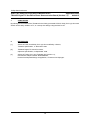
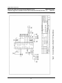
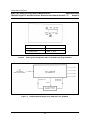
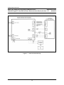
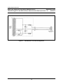
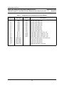
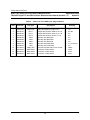
APPLICATION NOTE
SAA7710T Dolby Pro-Logic Plug-In Module Kit
for TDA9875 Digital TV Sound Processor
Demonstration Board (Version 1.1)
AN96115
Philips
Semiconductors
Philips Semiconductors
SAA7710T Dolby Pro-Logic Plug-In Module Kit for
Application Note
TDA9875 Digital TV Sound Processor Demonstration Board (Version 1.1)
AN96115
Abstract
A simple plug-in module for the TDA9875 demonstration board has been developed at
Philips Semiconductors Systems Laboratory Southampton (PS-SLS). Based on the SAA7710T IC, the
module adds Dolby Pro-Logic Surround Sound decoding facilities to this Digital TV Sound Processor.
The module kit, and its method of use, are outlined.
Purchase of Philips I2C components conveys a
license under the Philips I2C patent to use the
components in the I2C system, provided the
system conforms to the I2C specifications
defined by Philips.
© Philips Electronics NV 1996
All rights are reserved. Reproduction in whole or in part is prohibited without the prior written consent of
the copyright owner.
The information presented in this document does not form part of any quotation, is believed to be
accurate and reliable, and may be changed without notice. No liability will be accepted by the publisher
for any consequence of its use. Publication thereof does not convey nor imply any license under
patent - or other industrial or intellectual property rights.
2
Philips Semiconductors
SAA7710T Dolby Pro-Logic Plug-In Module Kit for
Application Note
TDA9875 Digital TV Sound Processor Demonstration Board (Version 1.1)
AN96115
APPLICATION NOTE
SAA7710T Dolby Pro-Logic Plug-In Module Kit
for TDA9875 Digital TV Sound Processor
Demonstration Board (Version 1.1)
AN96115
Author(s)
V Pham
Philips Semiconductors Systems Laboratory Southampton, England
Keywords:
TV/Set-Top Box
Dolby Pro-Logic Surround Sound
Digital TV Sound Processor
Module Kit
SAA7710T
TDA9875
Date: 22 October, 1996
3
Philips Semiconductors
SAA7710T Dolby Pro-Logic Plug-In Module Kit for
Application Note
TDA9875 Digital TV Sound Processor Demonstration Board (Version 1.1)
AN96115
Summary
A SAA7710T Dolby Pro-Logic Surround Sound DSP Core Plug-in Module Kit for the TDA9875 Digital
TV Sound Processor Demonstration Board has been built, and it demonstrates how simple it is to
interface the SAA7710T to the TDA9875.
4
Philips Semiconductors
SAA7710T Dolby Pro-Logic Plug-In Module Kit for
Application Note
TDA9875 Digital TV Sound Processor Demonstration Board (Version 1.1)
AN96115
Table of Contents
Page Number
1
INTRODUCTION
7
2
CONTENTS OF KIT
7
3
ADDITIONAL REQUIREMENTS (NOT SUPPLIED)
7
4
PRINCIPLE OF OPERATION
8
5
INSTALLATION NOTES
8
6
INSTRUCTIONS TO GET STARTED
9
7
CONCLUSION
10
8
REFERENCES
10
List of Tables
1
Component List of the SAA7710T Plug-In Module
15
2
Parts List of the SAA7710T Plug-In Module
16
List of Figures
1
2
3
4
5
Schematic Diagram of the SAA7710T Plug-In Module
PCB Lay-Out Component Side of the SAA7710T Plug-In Module
Simplified Block Diagram for SAA7710T and TDA9875
Interconnection Set-Up
‘Hardwareless’ I2C Cable Configuration
5
11
12
12
13
14
Philips Semiconductors
SAA7710T Dolby Pro-Logic Plug-In Module Kit for
Application Note
TDA9875 Digital TV Sound Processor Demonstration Board (Version 1.1)
AN96115
6
Philips Semiconductors
SAA7710T Dolby Pro-Logic Plug-In Module Kit for
Application Note
TDA9875 Digital TV Sound Processor Demonstration Board (Version 1.1)
AN96115
1
INTRODUCTION
A cost effective solution for Dolby Pro-Logic Surround Sound in a TV, or a set-top box, can be
implemented using the Dolby Pro-Logic Surround Sound DSP Core IC SAA7710T and the
TDA9875 Digital TV Sound Processor IC. To demonstrate how simple it is to interface the SAA7710T
with the TDA9875, Philips Semiconductors Systems Laboratory Southampton (PS-SLS) has built an
SAA7710T Plug-in Module Kit, to be used with the Digital TV Sound Processor TDA9875 Demonstration
Board from Philips Semiconductors Systems Laboratory Hamburg (PS-SLH).
This version of the board (Version 1.1, PCAL5193-1 PCB), omits provision for unnecessary connectors
included in Version 1.0, PCAL5193-0 PCB.
2
3
CONTENTS OF KIT
•
SAA7710T plug-in module, PCB number: PCAL5193-1 (see Figure 1 on Page 11
and Figure 2 on Page 12).
•
I2C Cable for PC.
•
SMB Lead (approximately 10 cm).
ADDITIONAL REQUIREMENTS (NOT SUPPLIED)
•
The TDA9875 demonstration board, PCB number: H5ACS23 (or its successor),
from PS-SLH.
•
The demonstration software for TDA9875 demonstration board, from PS-SLH.
•
The
demonstration
software
Philips Semiconductors Nijmegen.
for
SAA7710T
It is assumed that the user is familiar with the operation of all of the above.
7
evaluation
kit,
from
Philips Semiconductors
SAA7710T Dolby Pro-Logic Plug-In Module Kit for
Application Note
TDA9875 Digital TV Sound Processor Demonstration Board (Version 1.1)
AN96115
4
PRINCIPLE OF OPERATION
The simplified block diagram for the SAA7710T and TDA9875 is shown in Figure 3 on Page 12.
The digitised left and right signals are fed from the TDA9875 I2S output port 1 to the SAA7710T I2S input
port 1, which returns Dolby processed left and right signals, plus centre and surround signals, to the
TDA9875 I2S input ports 1 and 2 respectively. These digital signals are converted by the four DACs in
the TDA9875 to analogue left and right signals on its main output, plus centre and surround signals on
its auxiliary output.
5
INSTALLATION NOTES
The interconnection set-up is shown in Figure 4 on Page 13.
The SAA7710T module (PCAL5193-1 PCB) plugs directly into sockets ST02, ST04 and ST05 of the
TDA9875 demonstration board (H5ACS23 PCB or its successor) from PS-SLH. A clock connection is
required from the SMB connector ‘SYSCLK’ on the TDA9875 board, to the SMB connector ‘SMB1’ on
the SAA7710T board. A short SMB cable is provided for this purpose.
The kit is intended for use with a single PC running both the TDA9875 and the SAA7710T demonstration
software. A special I2C interface cable is provided which should connect the printer port of the PC to
socket ST03 on the TDA9875 board (see Figure 5 on Page 14 for new cable make-up).
This cable is configured for the SAA7710T software. To make the TDA9875 software work with this
cable its I2C configuration must be set to ‘hardwareless’.
The interface cable supplied does not support flag0/flag1 facilities in the SAA7710T debugger software.
It contains only I2C connections and not the extra flag wires.
The system utilises the auxiliary (headphone) outputs of the TDA9875 for the centre and surround
channels. Connect the left and right outputs from socket ST13, and the centre and surround outputs from
socket ST12 (‘centre’ to the ‘left’ channel), to your power amplifiers.
Connect a (Dolby Pro-Logic encoded) stereo signal source to the SCART 1 input, socket ST08, on the
TDA9875 board. (SCART 2, or other input, may be used but modify the TDA9875 ‘ADC source’ setting
accordingly.)
There is no hardware reset switch on the SAA7710T board, but the reset pin of the IC is connected to
port 2 of the TDA9875. Therefore the SAA7710T can be reset from the TDA9875 software by taking
port 2 low and then high again.
8
Philips Semiconductors
SAA7710T Dolby Pro-Logic Plug-In Module Kit for
Application Note
TDA9875 Digital TV Sound Processor Demonstration Board (Version 1.1)
AN96115
6
INSTRUCTIONS TO GET STARTED
•
Always apply power to the demonstration boards after switching on the PC to
prevent damage to PC printer port.
•
The 2 jumpers, JU01 and JU03 on the TDA9875 demo-board, should be fitted to
provide +5 V supply to the SAA7710T plug-in module.
Run the TDA9875 software first and check the following:
•
All relevant level controls may be set to 0 db, and the balance controls should be
set centrally.
•
In the Signal Paths dialogue box, check that the ‘ADC in, Source’ is set to
‘Scart1 in’ (or otherwise as appropriate).
•
In the Features Interface dialogue box, check the following:
•
•
•
The ‘IIS1 out, Source’ is ‘ADC’, ‘L, R’. (NB: take great care that this, and
similar controls, are set to ‘L,R’. By default they reset otherwise and this
may in the Dolby system mute the left and right channels.)
•
The ‘System Clock’ is set to ‘512 x Fs’ (=16.384 MHz).
The ‘Serial Audio’ is set to ‘IIS’.
On the Main Screen check that:
•
The ‘Loudspeaker Source’ is set to ‘IIS1’, ‘L,R’.
•
The ‘Headphone Source’ is set to ‘IIS2’, ‘L,R’.
Using the Sound IF dialogue box, reset the SAA7710 by taking TDA9875 port #2
low, and then high again. (NB: press ‘OK’ after each stage. Do not just select ‘low’
and then ‘high’, otherwise the ‘low’ will not have been sent.)
Leave the TDA9875 software running.
Run the SAA7710T demonstration software. (During this initialisation, the TDA9875 software may return
with a I2C message dialogue box, which asks if you want to suppress subsequent messages. Indicate
‘Yes’ and toggle back to the SAA7710T software.)
Check the following:
•
All relevant level controls may be set to 0 dB.
•
Input 1 is selected. (NB: this SAA7710T module does not support input 2.)
•
The Decoder Main Mode is ‘Full Dolby Pro Logic’.
•
The Centre Channel Mode is ‘Normal’.
Check for correct operation by running the noise generator.
NB: If there are unexpected results, check the relevant TDA9875 channel settings are all ‘L, R’.
9
Philips Semiconductors
SAA7710T Dolby Pro-Logic Plug-In Module Kit for
Application Note
TDA9875 Digital TV Sound Processor Demonstration Board (Version 1.1)
AN96115
7
CONCLUSION
By utilising the four DACs of the TDA9875 for the Dolby processed L/R/C/S, Dolby Pro-Logic Surround
Sound can be easily added to a TV, or a set-top box design using the SAA7710T.
8
REFERENCES
[1]
SAA7710T DSP Core/Dolby Pro-Logic Surround/Dolby 3 Stereo,
Tentative Specification, 17 November 1995.
[2]
TDA9875 Digital TV Sound Processor,
Objective Specification, 03 September 1996.
[3]
SAA7710T Dolby Pro-Logic Evaluation Kit (Version 1.0),
User Manual, Report number: NDA/UM95001,
Product Development/Design & Application, Consumer ICs Nijmegen.
10
Philips Semiconductors
Figure 1
Schematic Diagram of the SAA7710T Plug-In Module
SAA7710T Dolby Pro-Logic Plug-In Module Kit for
Application Note
TDA9875 Digital TV Sound Processor Demonstration Board (Version 1.1)
AN96115
11
Philips Semiconductors
SAA7710T Dolby Pro-Logic Plug-In Module Kit for
Application Note
TDA9875 Digital TV Sound Processor Demonstration Board (Version 1.1)
AN96115
Figure 2
JOB ID NAME
PCAL5193-1
LAYER No_
102 & 103
LAYER TITLE
SMD 7 SoIC
PCB Lay-Out Component Side of the SAA7710T Plug-In Module
Figure 3
Simplified Block Diagram for SAA7710T and TDA9875
12
Philips Semiconductors
SAA7710T Dolby Pro-Logic Plug-In Module Kit for
Application Note
TDA9875 Digital TV Sound Processor Demonstration Board (Version 1.1)
AN96115
Figure 4
Interconnection Set-Up
13
Philips Semiconductors
SAA7710T Dolby Pro-Logic Plug-In Module Kit for
Application Note
TDA9875 Digital TV Sound Processor Demonstration Board (Version 1.1)
AN96115
Figure 5
‘Hardwareless’ I2C Cable Configuration
14
Philips Semiconductors
SAA7710T Dolby Pro-Logic Plug-In Module Kit for
Application Note
TDA9875 Digital TV Sound Processor Demonstration Board (Version 1.1)
AN96115
Table 1
Component List of the SAA7710T Plug-In Module
Component
Part Type
Value
C1
C2
C3
C4
C5
C6
C7
C8
R1
R2
R3
R4
SMB1
ST01
ST02
ST03
U1
0805
0805
1206
0805
0805
0805
0805
0805
RC-11
RC-11
RC-11
RC-11
SMB_SKT
MKF19393
MKF19394
MKF19397
SAA7710T
100n
100n
470n
100n
10n
39p
10p
100n
4k7
100R
100R
100 k
Description
SM Cap 100n 0805 X7R
SM Cap 100n 0805 X7R
SM Cap 470n 1206 X7R
SM Cap 100n 0805 X7R
SM Cap 10n 0805 X7R
SM Cap 39p 0805 NPO
SM Cap 10p 0805 NPO
SM Cap 100n 0805 X7R
Philips SMT resistor 4k7 5% 0.1 W
Philips SMT resistor 100R 5% 0.1 W
Philips SMT resistor 100R 5% 0.1 W
Philips SMT resistor 100 k 5% 0.1 W
Sub-min bayonet snap-on PC socket (m)
Connector 7 Way Stocko
Connector 3 Way Stocko
Connector 4 Way Stocko
Dolby Surround Pro-Logic Core
15
Philips Semiconductors
SAA7710T Dolby Pro-Logic Plug-In Module Kit for
Application Note
TDA9875 Digital TV Sound Processor Demonstration Board (Version 1.1)
AN96115
Table 2
Parts List of the SAA7710T Plug-In Module
Item
Code No:
Part Type
1
2
3
4
5
6
7
8
9
10
11
12
13
10017710
20930101
20930104
20930472
40890109
40890399
40897103
40897104
40906474
81130010
86162034
86162044
86162074
SAA7710T
RC-11
RC-11
RC-11
0805
0805
0805
0805
1206
SMB_SKT
MKF19393
MKF19394
MKF19397
Description
Dolby Surround Pro-Logic Core
Philips SMT resistor 100R 5% 0.1 W
Philips SMT resistor 100 k 5% 0.1 W
Philips SMT resistor 4k7 5% 0.1 W
SM Cap 10p 0805 NPO
SM Cap 39p 0805 NPO
SM Cap 10n 0805 X7R
SM Cap 100n 0805 X7R
SM Cap 470n 1206 X7R
Sub-min bayonet snap-on PC socket
Connector 3 Way Stocko
Connector 4 Way Stocko
Connector 7 Way Stocko
16
Quantity
1
2
1
1
1
1
1
4
1
1
1
1
1
U1
R2 R3
R4
R1
C7
C6
C5
C1 C2 C4 C8
C3
SMB1
ST02
ST03
ST01