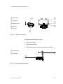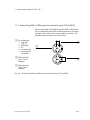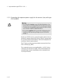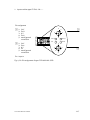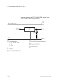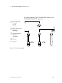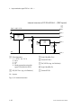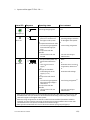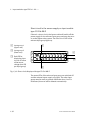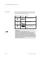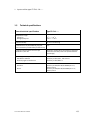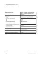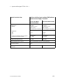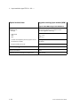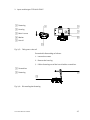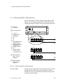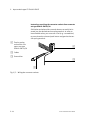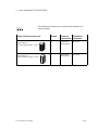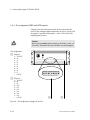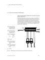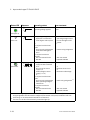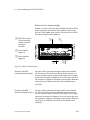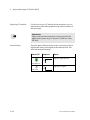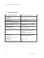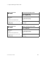
1
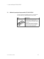
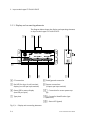
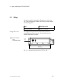
Compact performance
Electronics
manual
CP modules
Input module
type
CP−E16...−M...−...
Input module
type
CP−E16−KL−IP20−Z
Output module
type
CP−A08...−M12−...
Manual
165 225
en 0802e
[730 690]
Contents and general instructions
Original . . . . . . . . . . . . . . . . . . . . . . . . . . . . . . . . . . . . . . . de
Edition . . . . . . . . . . . . . . . . . . . . . . . . . . . . . . . . . . en 0802e
Designation . . . . . . . . . . . . . . . . . . . . . . . . . . P.BE−CPEA−EN
Orderno. . . . . . . . . . . . . . . . . . . . . . . . . . . . . . . . . . 165 225
E (Festo AG&Co. KG, D73726 Esslingen, Federal Republic of Germany, 2008)
Internet: http://www.festo.com
E−Mail: [email protected]
The copying, distribution and utilization of this document as well as the
communication of its contents to others without expressed authorization
is prohibited. Offenders will be held liable for the payment of damages.
All rights reserved, in particular the right to carry out patent, utility model
or ornamental design registration.
Festo P.BE−CPEA−EN en 0802e
I
Contents and general instructions
II
Festo P.BE−CPEA−EN en 0802e
Contents and general instructions
Contents
Designated use . . . . . . . . . . . . . . . . . . . . . . . . . . . . . . . . . . . . . . . . . . . . . . . . . . . . . . . .
Target group . . . . . . . . . . . . . . . . . . . . . . . . . . . . . . . . . . . . . . . . . . . . . . . . . . . . . . . . . .
Service . . . . . . . . . . . . . . . . . . . . . . . . . . . . . . . . . . . . . . . . . . . . . . . . . . . . . . . . . . . . . . .
Important user instructions . . . . . . . . . . . . . . . . . . . . . . . . . . . . . . . . . . . . . . . . . . . . . .
Notes on the use of this manual . . . . . . . . . . . . . . . . . . . . . . . . . . . . . . . . . . . . . . . . . . .
V
VI
VI
VII
IX
1.
Input modules type CP−E16...−M...−... . . . . . . . . . . . . . . . . . . . . . . . . . . . . . .
1−1
1.1
1.1.1
1.2
1.3
1.3.1
1.3.2
1−3
1−4
1−6
1−10
1−11
1.3.3
1.3.4
1.4
1.5
Function of input modules type CP−E16...−M...−... . . . . . . . . . . . . . . . . . . . . . .
Display and connecting elements . . . . . . . . . . . . . . . . . . . . . . . . . . . . . . . . . .
Fitting . . . . . . . . . . . . . . . . . . . . . . . . . . . . . . . . . . . . . . . . . . . . . . . . . . . . . . . .
Installation . . . . . . . . . . . . . . . . . . . . . . . . . . . . . . . . . . . . . . . . . . . . . . . . . . . .
Determining PNP or NPN operation (only with type CP−E16−M8−Z) . . . . . . . .
Connecting the separate power supply for the sensors
(only with type CP−E16−M8−Z) . . . . . . . . . . . . . . . . . . . . . . . . . . . . . . . . . . . . .
Connecting the sensors . . . . . . . . . . . . . . . . . . . . . . . . . . . . . . . . . . . . . . . . . .
Connecting the input module . . . . . . . . . . . . . . . . . . . . . . . . . . . . . . . . . . . . .
Instructions on commissioning . . . . . . . . . . . . . . . . . . . . . . . . . . . . . . . . . . . .
Technical specifications . . . . . . . . . . . . . . . . . . . . . . . . . . . . . . . . . . . . . . . . . .
2.
Input module type CP−E16−KL−IP20−Z . . . . . . . . . . . . . . . . . . . . . . . . . . . . . .
2−1
2.1
2.1.1
2.2
2.3
2.3.1
2.3.2
2.3.3
2.3.4
2.3.5
2.3.6
2.3.7
2.4
Method of operation of input module CP−E16−KL−IP20−Z . . . . . . . . . . . . . . . .
Display and connecting elements . . . . . . . . . . . . . . . . . . . . . . . . . . . . . . . . . .
Fitting . . . . . . . . . . . . . . . . . . . . . . . . . . . . . . . . . . . . . . . . . . . . . . . . . . . . . . . .
Installation . . . . . . . . . . . . . . . . . . . . . . . . . . . . . . . . . . . . . . . . . . . . . . . . . . . .
Determining PNP or NPN operation . . . . . . . . . . . . . . . . . . . . . . . . . . . . . . . .
Connecting the separate power supply for the sensors . . . . . . . . . . . . . . . . .
Connecting the sensors . . . . . . . . . . . . . . . . . . . . . . . . . . . . . . . . . . . . . . . . . .
Pin assignment (PNP and NPN inputs) . . . . . . . . . . . . . . . . . . . . . . . . . . . . . .
Circuitry examples of PNP inputs . . . . . . . . . . . . . . . . . . . . . . . . . . . . . . . . . .
Circuitry examples of NPN inputs . . . . . . . . . . . . . . . . . . . . . . . . . . . . . . . . . .
Connecting the input module . . . . . . . . . . . . . . . . . . . . . . . . . . . . . . . . . . . . .
Instructions on commissioning . . . . . . . . . . . . . . . . . . . . . . . . . . . . . . . . . . . .
2−3
2−4
2−5
2−8
2−9
2−10
2−13
2−16
2−17
2−20
2−23
2−25
Festo P.BE−CPEA−EN en 0802e
1−12
1−15
1−26
1−28
1−33
III
Contents and general instructions
2.5
Technical specifications . . . . . . . . . . . . . . . . . . . . . . . . . . . . . . . . . . . . . . . . . . 2−29
3.
Output modules type CP−A08...−M12−... . . . . . . . . . . . . . . . . . . . . . . . . . . . . .
3−1
3.1
3.2
3.3
3.3.1
3.3.2
3.3.3
3.4
3.5
Summary . . . . . . . . . . . . . . . . . . . . . . . . . . . . . . . . . . . . . . . . . . . . . . . . . . . . . .
Fitting . . . . . . . . . . . . . . . . . . . . . . . . . . . . . . . . . . . . . . . . . . . . . . . . . . . . . . . .
Installation . . . . . . . . . . . . . . . . . . . . . . . . . . . . . . . . . . . . . . . . . . . . . . . . . . . .
Connecting the actuators . . . . . . . . . . . . . . . . . . . . . . . . . . . . . . . . . . . . . . . . .
Connecting the output module . . . . . . . . . . . . . . . . . . . . . . . . . . . . . . . . . . . .
Connecting the load voltage . . . . . . . . . . . . . . . . . . . . . . . . . . . . . . . . . . . . . .
Instructions on commissioning . . . . . . . . . . . . . . . . . . . . . . . . . . . . . . . . . . . .
Technical specifications . . . . . . . . . . . . . . . . . . . . . . . . . . . . . . . . . . . . . . . . . .
3−3
3−4
3−5
3−6
3−13
3−14
3−17
3−20
A.
Index . . . . . . . . . . . . . . . . . . . . . . . . . . . . . . . . . . . . . . . . . . . . . . . . . . . . . . . . .
A−1
IV
Festo P.BE−CPEA−EN en 0802e
Contents and general instructions
Designated use
The CP modules described in this manual are intended ex
clusively for use on a CP string, an axis interface string or a
CP branch line in conjunction with a CP field bus node, the
Smart Positioning Controller type SPC200 or the Powerbox
type CP−FB−TBOX−SUBD9. CP modules and CP cables are only
to be used as follows:
in accordance with designated use
in its/their original state
without any modifications by the user
in faultless technical condition.
When used together with commercially available compo
nents, such as sensors and actuators, the specified limits for
pressures, temperatures, electrical data, torques etc. must be
observed. National and local safety regulations must also be
observed. All CP modules comply with protection class III.
Warning
S Use only PELV circuits as per IEC/DIN EN 60204−1 (Pro
tective Extra−Low Voltage, PELV) for the electrical supply.
Consider also the general requirements for PELV circuits
in accordance with IEC/DIN EN 60204−1.
S Use power supplies which guarantee reliable electrical
isolation of the operating voltage as per IEC/DIN EN
60204−1.
Festo P.BE−CPEA−EN en 0802e
V
Contents and general instructions
Target group
This manual is directed exclusively at technicians trained in
control and automation technology.
Service
Please consult your local Festo repair service if you have any
technical problems.
VI
Festo P.BE−CPEA−EN en 0802e
Contents and general instructions
Important user instructions
Danger categories
This manual contains instructions on the possible dangers
which may occur if the product is not used correctly. These
instructions are marked (Warning, Caution, etc), printed on a
shaded background and marked additionally with a picto
gram. A distinction is made between the following danger
warnings:
Warning
This means that failure to observe this instruction may
result in serious personal injury or damage to property.
Caution
This means that failure to observe this instruction may
result in personal injury or damage to property.
Please note
This means that failure to observe this instruction may
result in damage to property.
The following pictogram marks passages in the text which
describe activities with electrostatically sensitive compo
nents.
Electrostatically sensitive components may be damaged if
they are not handled correctly.
Festo P.BE−CPEA−EN en 0802e
VII
Contents and general instructions
Marking special information
The following pictograms mark passages in the text contain
ing special information.
Pictograms
Information:
Recommendations, tips and references to other sources of
information.
Accessories:
Information on necessary or sensible accessories for the
Festo product.
Environment:
Information on environment−friendly use of Festo products.
Text markings
S
The bullet indicates activities which may be carried out in
any order.
1. Figures denote activities which must be carried out in the
numerical order specified.
VIII
Hyphens indicate general activities.
Festo P.BE−CPEA−EN en 0802e
Contents and general instructions
Notes on the use of this manual
CP I/O modules are available in the designs PNP (positive−
switching) and NPN (negative−switching). The positive−switch
ing modules with M12 connectors are available in 4−pin and
5−pin designs. The 5−pin design offers an earthing connection.
This manual contains general basic information on the
method of operation, and on fitting, installing and commis
sioning CP systems.
This manual refers to:
Input modules
PNP:
CP−E16−M8
CP−E16−M12x2
CP−E16−M12x2−5POL
NPN:
CP−E16N−M8
CP−E16N−M12x2
PNP or NPN:
CP−E16−M8−Z
CP−E16−KL−IP20−Z
Output modules
PNP:
CP−A08−M12
CP−A08−M12−5POL
NPN:
CP−A08N−M12
Information on further modules, as well as basic information
which must be observed in conjunction with the higher−order
system, can be found in the manuals for the relevant systems.
Festo P.BE−CPEA−EN en 0802e
IX
Contents and general instructions
Manuals on the CP system
Periph
erals
Manual
CP system, installation and commissioning"
type P.BE−CPSYS−...
Contents
General basic information on the method of operation, fitting, installation
and commissioning of CP systems.
Manual
CP field bus node,
programming and
diagnosis"
type P.BE−CP−FB...
or P.BE−VIFB...−10...
CPV valve terminal,
pneumatics" or CPA
valve terminal, pneu
matics"
type P.BE−CPV−...
or P.BE−CPA−...
CP modules,
electronics"
type P.BE−CPEA−...
Contents
Special information on
commissioning, pro
gramming and diag
nosing related to the
node used.
Information on fitting,
installing and commis
sioning CPA or CPV
valve terminals
Information on fitting,
installing and commis
sioning CP I/O
modules
Ó
ÔÔ
Ô
Ô
ÔÔÔÔ
Fig.0/1: Manuals on the CP system
X
Festo P.BE−CPEA−EN en 0802e
Contents and general instructions
Manuals on the SPC200 Smart Positioning Controller
Peripherals
Manuals
SPC200 Smart
Positioning Controller,
User manual
type P.BE−SPC200−...
Manual WinPISA
type P.SW−WIN−PISA−...
Manuals on:
proportional directional control
valves
service unit
position measuring system
cylinder or linear drives
Contents
Installation, commis
sioning and diagnosis
with SPC200;
standard components
and modules
Functions of the
WinPISA software
package
Description
CPV valve terminal
pneumatics
type P.BE−CPV−...
CP modules
electronics
type P.BE−CPEA−...
Contents
Information on the
CPV valve terminals
Information on the
CP I/O modules
Fig.0/2: Manuals on the SPC200
Festo P.BE−CPEA−EN en 0802e
XI
Contents and general instructions
XII
Festo P.BE−CPEA−EN en 0802e
Input modules type CP−E16...−M...−...
Chapter 1
Festo P.BE−CPEA−EN en 0802e
1−1
1. Input modules type CP−E16...−M...−...
Contents
1.
Input modules type CP−E16...−M...−... . . . . . . . . . . . . . . . . . . . . . . . . . . . . . .
1.1
1.1.1
1.2
1.3
1.3.1
1.3.2
Function of input modules type CP−E16...−M...−... . . . . . . . . . . . . . . . . . . . . . . 1−3
Display and connecting elements . . . . . . . . . . . . . . . . . . . . . . . . . . . . . . . . . . 1−4
Fitting . . . . . . . . . . . . . . . . . . . . . . . . . . . . . . . . . . . . . . . . . . . . . . . . . . . . . . . . 1−6
Installation . . . . . . . . . . . . . . . . . . . . . . . . . . . . . . . . . . . . . . . . . . . . . . . . . . . . 1−10
Determining PNP or NPN operation (only with type CP−E16−M8−Z) . . . . . . . . 1−11
Connecting the separate power supply for the sensors (only with type CP−E16−M8−Z)
1−12
Connecting the sensors . . . . . . . . . . . . . . . . . . . . . . . . . . . . . . . . . . . . . . . . . . 1−15
Connecting the input module . . . . . . . . . . . . . . . . . . . . . . . . . . . . . . . . . . . . . 1−26
Instructions on commissioning . . . . . . . . . . . . . . . . . . . . . . . . . . . . . . . . . . . . 1−28
Technical specifications . . . . . . . . . . . . . . . . . . . . . . . . . . . . . . . . . . . . . . . . . . 1−33
1.3.3
1.3.4
1.4
1.5
1−2
1−1
Festo P.BE−CPEA−EN en 0802e
1. Input modules type CP−E16...−M...−...
1.1
Function of input modules type CP−E16...−M...−...
CP input modules provide digital inputs for connecting sen
sors and enable e.g. cylinder positions to be scanned. A dis
tinction is made between the following types:
Type
Explanation
CP−E16−M12x2−...
Provides 16 PNP inputs; sensor connec
tions via 8 sockets with M12 thread
CP−E16N−M12x2
CP−E16−M8
CP−E16N−M8
CP−E16−M8−Z
Festo P.BE−CPEA−EN en 0802e
Provides 16 NPN inputs;
sensor connections via 8 sockets with M12
thread
Provides 16 PNP inputs;
sensor connections via 16 sockets with M8
thread
Provides 16 NPN inputs;
sensor connections via 16 sockets with M8
thread
Provides 16 PNP or 16 NPN inputs and has
its own connection for supplying the sen
sor voltage
1−3
1. Input modules type CP−E16...−M...−...
1.1.1 Display and connecting elements
The diagram below shows, as an example, the display and
connecting elements on the input module type
CP−E16...−M12x2.
3
2
4
1
9
8
5
7
6
1 Status LED (green)
2 Identification for input type:
INPUT−P for PNP inputs
INPUT−N for NPN inputs
3 Sensor connections
4 Yellow LED for status display
(one LED per input)
5 Groove for identification signs
(IBS6x10)
6 Earth/ground connection
7 Type plate
8 Protective cap
9 CP connection
Fig.1/1: Display and connecting elements
1−4
Festo P.BE−CPEA−EN en 0802e
1. Input modules type CP−E16...−M...−...
The diagram below shows the additional display and operat
ing elements on the input module type CP−E16−M8−Z.
1 Connection for
the power supply
to the sensors
1
2
2 Red LED for
displaying short
circuits or failure
of the sensor
voltage (one LED
per input group)
2
Fig.1/2: Additional elements of type CP−E16−M8−Z
Festo P.BE−CPEA−EN en 0802e
1−5
1. Input modules type CP−E16...−M...−...
1.2
Fitting
Input modules are intended for fitting onto a wall or a hat rail.
If you are fitting the module onto a wall, you will require the
following space:
Fitting onto a wall
1−6
Type
Mounting area
CP−E16...−M8
approx. 150 x 66 mm
CP−E16−M8−Z
approx. 217 x 66 mm
CP−E16...−M12x2−...
approx. 141 x 78 mm
The diagram below shows the dimensions for the four
threaded holes of M4 screw size.
Festo P.BE−CPEA−EN en 0802e
1. Input modules type CP−E16...−M...−...
1 Input module,
type
CP−E16...−M12x2−...
2 Input module,
131.9 mm
1
63 mm
type CP−E16...−M8
3 Input module,
type CP−E16−M8−Z
2
40 mm
139.9 mm
3
40 mm
207.9 mm
Fig.1/3: Mounting dimensions for CP−E16...−M...−...
Festo P.BE−CPEA−EN en 0802e
1−7
1. Input modules type CP−E16...−M...−...
In order to fit the module onto a hat rail, you will require
fastening kit CP−TS−HS35. This kit consists of 2 fastenings,
2 M4x12 screws and two washers.
Fitting onto a hat rail
Proceed as follows when fitting the modules onto a hat rail:
1. Make sure that the mounting surface can support the
weight of the node.
2. Fit a hat rail (support rail as per EN50022 − 35x15; width
35 mm, height 15 mm).
3. Fasten the hat rail to the fastening surface at intervals of
at least every 100 mm.
4. Let both fastenings on the hat rail snap into place (see
Fig.1/4).
5. Fasten the housing to the fastening with the screws sup
plied, as shown in the diagram below.
6. Tighten the screws. The fastening and the housing will
then be clamped firmly on the hat rail.
1−8
Festo P.BE−CPEA−EN en 0802e
1. Input modules type CP−E16...−M...−...
1 Fastening
1
2 Housing
2
3
3 M4x12 screw
4 Washer
4
5 Hat rail
5
Fig.1/4: Fitting onto a hat rail
Proceed with dismantling as follows:
1. Loosen the screws.
2. Remove the housing.
3. Lift the fastening out of the hat rail with a screwdriver.
1 Screwdriver
1
2 Fastening
2
Fig.1/5: Dismantling the fastening
Festo P.BE−CPEA−EN en 0802e
1−9
1. Input modules type CP−E16...−M...−...
1.3
Installation
Warning
Before carrying out installation and maintenance work,
switch off the following:
the operating and load voltages on the higher−order sys
tem (e.g. CP field bus node)
if necessary, the separate supply voltages.
You can thereby avoid:
unexpected movements of the connected actuators
non−defined switching states of the electronic compo
nents.
Warning
Connect the earth connection on the side of the housing
(see Fig.1/1) with low impedance (short cable with large
cross−sectional area) to the earth potential.
In this way you can avoid faults due to electromagnetic
influences and ensure electromagnetic compatibility in
accordance with EMC guidelines.
1−10
Festo P.BE−CPEA−EN en 0802e
1. Input modules type CP−E16...−M...−...
1.3.1 Determining PNP or NPN operation (only with type CP−E16−M8−Z)
Input module type CP−E16−M8−Z provides PNP or NPN inputs.
You can determine either PNP or NPN operation by installing
a bridge in the socket of the sensor supply connection. The
following views show the rear of the socket.
1 Pin assignment
1: + 24 V DC
± 25 %
2: PNP/NPN
3. 0 V
4: not connected
5: earth/ground
connection
2
1
2 PNP operation
(pins 2 and 3
bridged)
3
3 NPN operation
(pins 2 and 1
bridged)
Fig.1/6: Determining PNP or NPN operation (only with type CP−E16−M8−Z)
Festo P.BE−CPEA−EN en 0802e
1−11
1. Input modules type CP−E16...−M...−...
1.3.2 Connecting the separate power supply for the sensors (only with type
CP−E16−M8−Z)
Warning
S Use only PELV circuits as per IEC/DIN EN 60204−1 (Pro
tective Extra−Low Voltage, PELV) for the electrical supply.
Consider also the general requirements for PELV circuits
in accordance with IEC/DIN EN 60204−1.
S Use power supplies which guarantee reliable electrical
isolation of the operating voltage as per IEC/DIN EN
60204−1.
By the use of PELV circuits, protection against electric shock
(protection against direct and indirect contact) is guaranteed
in accordance with IEC/EN 60204−1 (Electrical equipment for
machines, General requirements).
The CP input module must be earthed to ensure that it func
tions correctly (e.g. EMC).
The connected sensors are supplied with + 24 V DC via the
connection for the sensor supply. The module enables sen
sors with high current consumption to be connected (max.
125 mA per sensor).
1−12
Festo P.BE−CPEA−EN en 0802e
1. Input modules type CP−E16...−M...−...
The following diagram shows the pin assignment of the con
nection as well as an example of a connection for PNP oper
ation (bridge between pins 2 and 3). See Determining PNP
or NPN operation", section 1.3.1.
1 Pin assignment
2
1: + 24 V DC
± 25 %
2: PNP/NPN
3. 0 V
4: not connected
5: earth/ground
connection
3
1
1
5
4
2 The sensor
voltage can be
switched off sep
arately; the oper
ating voltage is
supplied via the
CP connection
2 3 1 4 5
0V
AC
24V
230V
DC
24V
2
Fig.1/7: Pin assignment and connection example of the sensor supply (PNP operation)
Festo P.BE−CPEA−EN en 0802e
1−13
1. Input modules type CP−E16...−M...−...
Potential equalization
The CP module has two earthing connections for potential
equalization:
on the connection for the sensor voltage supply (pin 5).
on the housing (earthing connection see Fig.1/7).
Please note
S Always connect the earth potential to pin 5 of the sensor
supply voltage.
S Connect the earth connection on the left−hand side of the
housing with low impedance (short cable with large
cross−sectional area) to the earth potential.
S With low−impedance connections you can ensure that
the housing of the module and the earth connection at
pin 5 have the same potential and that there are no
equalizing currents.
In this way you can avoid faults due to electromagnetic
influences and ensure electromagnetic compatibility in
accordance with EMC guidelines.
1−14
Festo P.BE−CPEA−EN en 0802e
1. Input modules type CP−E16...−M...−...
1.3.3 Connecting the sensors
Caution
If you are using input module type CP−E16−M8−Z, make
sure that pin 2 of the sensor supply connection is bridged
in accordance with the operating method of your system
(either PNP or NPN operation, see section 1.3.1).
Use the following cables or plugs for connecting the sensors:
Type
Plugs
Cable
CP−E16...−M12x2
SEA−GS−7 (PG7)
SEA−WS−7 (PG7)
KM12−DUO−...
CP−E16−M12x2−5POL
Use plugs with union nuts
with M12x1 thread.
CP−E16...−M8
and
CP−E16−M8−Z
Use plugs with union nuts
with M8x1 thread (outer
diameter max. 12mm).
KM8−M8−GSGD−...
Fasten the plugs with the aid of the union nut in order to pre
vent unintentional loosening, e.g. due to shock. Seal the un
used sensor connections with the protective caps supplied.
Only in this way can you comply with protection class IP 65.
Festo P.BE−CPEA−EN en 0802e
1−15
1. Input modules type CP−E16...−M...−...
Pin assignment (PNP and NPN inputs)
The diagrams below show, as an example, the pin assignment
of the sensor connections of the various CP input modules.
Pin assignment
1
1 1: 24V
1
4: Ex+1
3. 0V
3
4
2 1: 24V
Ex+1
4: Ex
3. 0V
Ex
4
Ex = Input x
3
1
2
Fig.1/8: Pin assignment of type CP−E16...−M8 and CP−E16−M8−Z
Pin assignment
4
1 1: 24V
2: Ex+1
3. 0V
4: Ex + 2
2 1: 24V
2: Ex+1
3. 0V
4: Ex
3
1
1
2
Ex+2
Ex
Ex = Input x
Ex+3
2
1
Ex+1
3
4
2
Fig.1/9: Pin assignment of type CP−E16...−M12x2
1−16
Festo P.BE−CPEA−EN en 0802e
1. Input modules type CP−E16...−M...−...
Pin assignment
2:
3.
4:
5:
Ex+3
0V
Ex+2
earth/ground
connection
2 1: 24V
2:
3.
4:
5:
1
4
1 1: 24V
5
3
1
2
Ex+2
Ex+3
Ex
Ex+1
0V
Ex
earth/ground
connection
Ex+1
2
1
3
2
5
4
Ex = Input x
Fig.1/10: Pin assignment of type CP−E16−M12x2−5POL
Festo P.BE−CPEA−EN en 0802e
1−17
1. Input modules type CP−E16...−M...−...
Internal structure of CP−E16−M8 (PNP inputs) and
CP−E16−M8−Z with PNP operation
1
24V + 10/− 15 %
2
Pin 1
3
Pin 4
4
0V
1 Pin assignment
1: 24V + 10/− 15 %
4: Ex
3. 0V
Pin 3
2 PLC/IPC Ex (e.g. via field bus)
3 Logic identifier Ex
4 Green LED Ex
Ex = Input x
Fig.1/11: Internal structure
1−18
Festo P.BE−CPEA−EN en 0802e
1. Input modules type CP−E16...−M...−...
Circuitry examples of CP−E16−M8 (PNP inputs) and
CP−E16−M8−Z with PNP operation
1 Pin assignment
3. 24V
4: Ex
3. 0V
1
1
4
2 Three−wire sensor
(positive−
switching)
3
2
3
4
3 Two−wire sensor
(positive−
switching)
4 Contact
Ex = Input x
Fig.1/12: Circuitry examples
Festo P.BE−CPEA−EN en 0802e
1−19
1. Input modules type CP−E16...−M...−...
Internal structure of CP−E16−M12x2−... (PNP inputs)
1
24V + 10/− 15 %
Pin 1
Pin 5
3
2
Pin 2
4
5
6
Pin 4
7
0V
Pin 3
1 Pin assignment
1:
2:
3.
4:
5:
+24V + 10/− 15 %
Ex+1
0V
Ex
Earth connection only with
type CP−E16−M12x2−5POL
2 PLC/IPC Ex+1 (e.g. via field bus)
3 Logic identifier Ex+1
4 Green LED Ex+1
5 PLC/IPC Ex (e.g. via field bus)
6 Logic identifier Ex
7 Green LED Ex
Ex = Input x
Fig.1/13: Internal structure
1−20
Festo P.BE−CPEA−EN en 0802e
1. Input modules type CP−E16...−M...−...
Circuitry examples of CP−E16−M12x2... (PNP inputs)
1 Pin assignment
3.
2:
3.
4:
5:
24V
Ex +1
0V
Ex
*)
4
1
5
1
3
2
2 Sensor 2 (Ex+1)
positive switching
3 2−way distributor
(T−piece)
4 Sensor 1 (Ex)
positive switching
*) Only with type
CP−16−M12x2−5POL
earth/ground
connection
Ex = Input x
4
2
3
Fig.1/14: Circuitry examples
Festo P.BE−CPEA−EN en 0802e
1−21
1. Input modules type CP−E16...−M...−...
Internal structure of CP−E16N−M8 (NPN inputs) and
CP−E16−M8−Z with NPN operation
1
0V
Pin 3
2
3
Pin 4
4
24V + 10/− 15 %
Pin 1
1 Pin assignment
1: 24V + 10/− 15 %
4: Ex
3. 0V
2 PLC/IPC Ex (e.g. via field bus)
3 Logic identifier Ex
4 Green LED Ex
Ex = Input x
Fig.1/15: Internal structure
1−22
Festo P.BE−CPEA−EN en 0802e
1. Input modules type CP−E16...−M...−...
Circuitry examples of CP−E16N−M8 (NPN inputs) and
CP−E16−M8−Z with NPN operation
1 Pin assignment
3. 24V
4: Ex
3. 0V
2 Three−wire sensor
(negative−
switching)
1
1
3
4
2
3
4
3 Two−wire sensor
(negative−
switching)
4 Contact
Ex = Input x
Fig.1/16: Circuitry examples
Festo P.BE−CPEA−EN en 0802e
1−23
1. Input modules type CP−E16...−M...−...
Internal structure of CP−E16N−M12x2 (NPN inputs)
1
0V
Pin 3
3
2
Pin 2
4
5
6
Pin 4
7
24V + 10/− 15 %
1 Pin assignment
1:
2:
3.
4:
+24 V + 10/− 15 %
Ex+1
0V
Ex
Pin 1
3 Logic identifier Ex+1
4 Green LED Ex+1
5 PLC/IPC Ex (via field bus)
2 PLC/IPC Ex+1 (e.g. via field bus)
6 Logic identifier Ex
Ex = Input x
7 Green LED Ex
Fig.1/17: Internal structure
1−24
Festo P.BE−CPEA−EN en 0802e
1. Input modules type CP−E16...−M...−...
Circuitry examples of CP−E16N−M12x2 (NPN inputs)
4
1
3
1
2
2
4
3
1 Pin assignment
1.
2:
3.
4:
24V
Ex+1
0V
Ex
2 Sensor 2 (Ex+1) (negative logic)
3 2−way distributor (T−piece, e.g. Festo
Duo cable; only 4−pin)
4 Sensor 1 (Ex) (negative logic)
Ex = Input x
Fig.1/18: Circuitry examples
Festo P.BE−CPEA−EN en 0802e
1−25
1. Input modules type CP−E16...−M...−...
1.3.4 Connecting the input module
Caution
Please observe the maximum permitted string lengths. You
can thereby avoid errors in data exchange between the
input module and the higher−order system (e.g. field bus
node).
Use only the following original cables for connecting the
modules:
For connection
to:
max. permitted string Cable type
length
Field bus node
with CP connection
10 m
Axis interface
typeSPC−AIF−...
See manual for the
SPC200
type P.BE−SPC200−...
Powerbox type
CP−FB−TBOX−...
See manual for the
higher−order system
KVI−CP−1−...
or
KVI−CP−2−...
KVI CP 2
(suitable for
drag chain)
The following functions are provided for the module via the
CP cable:
1−26
Operating voltage for the internal electronics
Connection for data exchange
in the case of input modules without connection for sup
plying the sensors:
Operating voltage for the connected sensors.
Festo P.BE−CPEA−EN en 0802e
1. Input modules type CP−E16...−M...−...
Input modules should be connected to one of the following:
to the CP connection of the higher−order system (field bus
node or axis interface or Powerbox)
to the CP connection of a CP output module
to the CP connection of a valve terminal.
Further information can be found in the relevant system manual.
Festo P.BE−CPEA−EN en 0802e
1−27
1. Input modules type CP−E16...−M...−...
1.4
Instructions on commissioning
Warning
Please be careful if the string assignment is modified at a
later stage.
After saving the string assignment/hardware configur
ation, check the address assignments of your higher−order
system before starting user programs.
You can thereby avoid:
addressing errors with unintentionally incorrectly fitted
CP modules.
When the string assignment on CP field bus nodes has been
modified (CP modules added or removed), you must save the
new string assignment by pressing the SAVE button on the
node. Proceed here as described in the manual CP system,
installation and commissioning".
When the string assignment has been modified on the
SPC200, the new hardware configuration must also be saved.
Proceed here as described in the manual for the SPC200 or in
the WinPISA manual.
Status LED
1−28
The operating status of the input module is indicated by the
status LED on the CP connection (see table below).
Festo P.BE−CPEA−EN en 0802e
1. Input modules type CP−E16...−M...−...
Status LED
Sequence
ON
Operating status
Error treatment
Operating voltage applied
None
Operating voltage not ap
plied or no connection to
the higher−order system
or
In conjunction with the CP node:
incorrect string assignment
ascertained during oper
ation
In conjunction with the
SPC200:
see user manual for the
SPC200
S Check the CP cable and the
operating voltage connection
on the higher−order system
or
Test phase when power sup
ply has been switched on
or
short circuit in sensor
supply 3)
or
With type CP−E16−M8−Z:
undervoltage in sensor
supply (< 17 V)
or
In conjunction with the CP
node:
incorrect string assignment
when operating voltage is
switched on
In conjunction with the
SPC200:
see user manual for the
SPC200
S None
OFF
LED lights up
ON
OFF
LED is out
ON
OFF
LED flashes
S correct string assignment
S see user manual type
P.BE−SPC200
or
S eliminate short circuit and,
if applicable, delete error 1)
or
S eliminate undervoltage
S check string assignment 2)
S see user manual type
P.BE−SPC200
1)
With type CP−E16−M8−Z the error will be deleted automatically With other modules the error will
be deleted when the input module is disconnected from the string or when the power supply is
switched on again on the higher−order system.
2) When the string assignment on CP field bus nodes has been modified (CP modules added or
removed), you must save the new string assignment by pressing the SAVE button on the node
(see Manual for the CP system, installation und commissioning").
3) With type CP−E16−M8−Z the short circuit LED on the relevant input group will light up.
Festo P.BE−CPEA−EN en 0802e
1−29
1. Input modules type CP−E16...−M...−...
Short circuit in the sensor supply on input module
type CP−E16−M8−Z
If there is a short circuit, the input module will switch off the
power supply for the relevant input group and pass the error
on to the higher−order system. The short circuit LED of the
relevant input group lights up.
1 Input group 1
(upper row)
3
2 Input group 2
1
(lower row)
3 Red LED for
displaying short
circuits or failure
of the sensor
voltage (one LED
per input group)
2
3
Fig.1/19: Short circuit displays with type CP−E16−M8−Z
The status LEDs of the relevant input group are switched off
and the relevant inputs supply a 0−signal. The other input
group remains ready to operate. When the short circuit is
eliminated, the error will be deleted automatically.
1−30
Festo P.BE−CPEA−EN en 0802e
1. Input modules type CP−E16...−M...−...
Short circuit in the sensor supply on input modules
without sensor supply connection
If there is a short circuit, the input module will switch off the
power supply for the sensors self−holding and pass the error
on to the higher−order system. The status LEDs will be
switched off and the inputs of the module supply a 0−signal.
When the short circuit has been eliminated, delete this error
as follows:
In conjunction with the CP node:
S
Disconnect the input module briefly from the string or
S
switch the operating voltage off and then on again.
In conjunction with the SPC200:
S
Replacing CP modules
For procedure see user manual type P.BE−SPC200
If a fault occurs on a CP module during operation, you can
replace the module during operation by another module of
the same type.
Please note
Please note here the instructions in the manual for the
higher−order system (e.g. CP system, CP field bus node,
SPC200).
Festo P.BE−CPEA−EN en 0802e
1−31
1. Input modules type CP−E16...−M...−...
Status display
There are one or two green LEDs next to the sensor connec
tions. These indicate the status of the signal at the relevant
output. The LEDs indicate the following:
Status LED
Sequence
ON
Status
logical 1 (signal present)
OFF
LED lights up
ON
LED is out
ON
OFF
LED flashes
logical 0 (no signal)
OFF
Only in the start−up phase when:
there is a 1−signal and
there is a string assignment
error
Please note
in conjunction with the CP field bus node:
If there is a string assignment error during the start−up
phase, the CP node will switch the power supply for the
input module, and thereby also for the connected sensors,
cyclically on and off. In this case, therefore, the status LEDs
and the LEDs of the connected sensors will flash, providing
there is a signal (logical 1).
1−32
Festo P.BE−CPEA−EN en 0802e
1. Input modules type CP−E16...−M...−...
1.5
Technical specifications
General technical specifications
Type CP−E16...−...
Temperature range:
Operation
Storage/transport
− 5 °C ... + 50 °C
− 20 °C ... + 70 °C
Relative humidity
95% non−condensing
Protection class as per EN 60529; plug con
nector inserted or provided with protective cap
IP65
Protection against electric shock as per
EN 60204−1 / IEC 204
(protection against direct and indirect contact) by
connection to a PELV power unit (Protected Extra
Low Voltage)
Electromagnetic compatibility
Interference emitted
Immunity against interference
Vibration and shock
Vibration
Shock
Festo P.BE−CPEA−EN en 0802e
Tested as per EN 55011, limit class B
Tested as per EN 50082−2
Tested as per DIN/IEC 68/EN60068 part 2−6;
severity class 2
Tested as per DIN/IEC 68/EN 60068 part 2−27;
severity class 2
1−33
1. Input modules type CP−E16...−M...−...
Special technical data
Type CP−E16−M8−Z; positive switching
(PNP) or negative switching (NPN)
operation
Digital inputs
Design
16 inputs as per IEC 1131−2 type 2 inputs
24 V DC, positive or negative switching
Logic level, positive switching
ON
OFF
Logic level negative switching
ON
OFF
PNP (reference 0 V):
≥ 8.6 V
≤6V
PNP (reference 24 V):
≤6V
≥ 8.6 V
Current consumption (at 24V) (input current
from sensor to input)
At logical 1"
typ. 8 mA
Response delay (at 24 V)
Typ. 3 ms
Sensor supply VD 24 V ±25 %
Max. 1 A per input group (electronic short−circuit
protection per group)
Electrical isolation
None
Internal current consumption of electronics
<40 mA
1−34
Festo P.BE−CPEA−EN en 0802e
1. Input modules type CP−E16...−M...−...
Special technical data
Positive−switching input modules (PNP) without
separate sensor supply connection
TypeCP−E16−M8 and
typeCP−E16−M12x2
TypeCP−E16−M12x2−5POL
16 inputs
as per IEC 1131−2
Type 2 inputs
24 V DC positive−switching
16 inputs
as per IEC 1131−2
Type 2 inputs
24 V DC negative−switching
Logic level
ON
OFF
> 11 V
<5V
≥ 8.6 V
≤6V
Current consumption (at 24V) (input
current from sensor to input)
At logical 1"
typ. 8 mA
At "logical 1"
typ. 6 mA
Response delay (at 24 V)
Typ. 5 ms
Typ. 3 ms
Sensor supply VD 24 V ± 25 %
Max. 0.5 A (electronic short−circuit protection)
Electrical isolation
None
Internal current consumption of
electronics
<40 mA
Digital inputs
Design
Festo P.BE−CPEA−EN en 0802e
Max. 90 mA
1−35
1. Input modules type CP−E16...−M...−...
Special technical data
Negative−switching input modules (NPN)
Type CP−E16N−M8 and type CP−E16N−M12x2
Digital inputs
Design
16 inputs as per IEC 1131−2 type 2 inputs
24 V DC negative−switching
Logic level
ON
OFF
< VD − 11 V
> VD − 5 V
Current consumption (at 24V) (input current
from sensor to input)
At logical 0"
typ. 8 mA
Response delay (at 24 V)
Typ. 5 ms
Sensor supply VD 24 V ± 25 %
Max. 0.5 A (electronic short−circuit protection)
Electrical isolation
None
Internal current consumption of electronics
Max. 90 mA
1−36
Festo P.BE−CPEA−EN en 0802e
Input module type CP−E16−KL−IP20−Z
Chapter 2
Festo P.BE−CPEA−EN en 0802e
2−1
2. Input module type CP−E16−KL−IP20−Z
Contents
2.
Input module type CP−E16−KL−IP20−Z . . . . . . . . . . . . . . . . . . . . . . . . . . . . . .
1−1
2.1
2.1.1
2.2
2.3
2.3.1
2.3.2
2.3.3
2.3.4
2.3.5
2.3.6
2.3.7
2.4
2.5
Method of operation of input module CP−E16−KL−IP20−Z . . . . . . . . . . . . . . . .
Display and connecting elements . . . . . . . . . . . . . . . . . . . . . . . . . . . . . . . . . .
Fitting . . . . . . . . . . . . . . . . . . . . . . . . . . . . . . . . . . . . . . . . . . . . . . . . . . . . . . . .
Installation . . . . . . . . . . . . . . . . . . . . . . . . . . . . . . . . . . . . . . . . . . . . . . . . . . . .
Determining PNP or NPN operation . . . . . . . . . . . . . . . . . . . . . . . . . . . . . . . .
Connecting the separate power supply for the sensors . . . . . . . . . . . . . . . . .
Connecting the sensors . . . . . . . . . . . . . . . . . . . . . . . . . . . . . . . . . . . . . . . . . .
Pin assignment (PNP and NPN inputs) . . . . . . . . . . . . . . . . . . . . . . . . . . . . . .
Circuitry examples of PNP inputs . . . . . . . . . . . . . . . . . . . . . . . . . . . . . . . . . .
Circuitry examples of NPN inputs . . . . . . . . . . . . . . . . . . . . . . . . . . . . . . . . . .
Connecting the input module . . . . . . . . . . . . . . . . . . . . . . . . . . . . . . . . . . . . .
Instructions on commissioning . . . . . . . . . . . . . . . . . . . . . . . . . . . . . . . . . . . .
Technical specifications . . . . . . . . . . . . . . . . . . . . . . . . . . . . . . . . . . . . . . . . . .
2−3
2−4
2−5
2−8
2−9
2−10
2−13
2−16
2−17
2−20
2−23
2−25
2−29
2−2
Festo P.BE−CPEA−EN en 0802e
2. Input module type CP−E16−KL−IP20−Z
2.1
Method of operation of input module CP−E16−KL−IP20−Z
CP input modules provide digital inputs for connecting sen
sors and enable e.g. cylinder positions to be scanned.
Festo P.BE−CPEA−EN en 0802e
Type
Explanation
CP−E16−KL−IP20−Z
Input module type CP−E16−KL−IP20−Z
provides 16 PNP or 16 NPN inputs and has
its own connection for the power supply to
the sensors.
It has three 10−pin optional connecting
sockets in screw or tension spring design
and is therefore particularly suited for
fitting into a control cabinet (IP20).
2−3
2. Input module type CP−E16−KL−IP20−Z
2.1.1 Display and connecting elements
The diagram below shows the display and operating elements
on input module type CP−E16−KL−IP20−Z.
1
2
3
4
9
8
7
6
6
5
4 CP connection
8 Earth/ground connection
5 Red LED for short circuit/overload
9 Sensor connections
display (one LED per input module)
6 Green LED for status display
(one LED per input)
7 Type plate
(8 inputs per input module)
10 Connection for sensor power sup
ply
11 Groove for identification signs
(IBS6x10)
12 Status LED (green)
Fig.2/1: Display and connecting elements
2−4
Festo P.BE−CPEA−EN en 0802e
2. Input module type CP−E16−KL−IP20−Z
2.2
Fitting
The input module is intended for fitting onto a wall or a hat
rail. If you are fitting the module onto a wall, you will require
the following space:
Fitting onto a wall
Type
Mounting surface
CP−E16−KL−IP20−Z
Approx. 175 x 66 mm
The diagram below shows the dimensions for the four
threaded holes of M4 screw size. You should fasten the
module with at least 3 screws.
1 Input module,
1
40 mm
type
CP−E16−KL−IP20−Z
166 mm
Fig.2/2: Mounting dimensions for CP−E16...−M...−...
Festo P.BE−CPEA−EN en 0802e
2−5
2. Input module type CP−E16−KL−IP20−Z
Hat rail fitting
You will require the following accessories for fitting the mod
ule onto a hat rail:
In order to fit the module onto a hat rail, you will require
fastening kit CP−TS−HS35. This kit consists of 2 fastenings,
2 M4x12 screws and two washers.
Proceed as follows when fitting the modules onto a hat rail:
1. Make sure that the mounting surface can support the
weight of the module.
2. Fit a hat rail (support rail as per EN50022 − 35x15; width
35 mm, height 15 mm).
3. Fasten the hat rail to the fastening surface at intervals of
at least every 100 mm.
4. Let both fastenings snap into place on the hat rail (see
Fig.1/4).
5. Fasten the housing to the fastening with the screws sup
plied, as shown in the diagram below.
6. Tighten the screws. The fastening and the housing will
then be clamped firmly on the hat rail.
2−6
Festo P.BE−CPEA−EN en 0802e
2. Input module type CP−E16−KL−IP20−Z
1 Fastening
1
2 Housing
2
3
3 M4x12 screw
4 Washer
4
5 Hat rail
5
Fig.2/3: Fitting onto a hat rail
Proceed with dismantling as follows:
1. Loosen the screws.
2. Remove the housing.
3. Lift the fastening out of the hat rail with a screwdriver.
1 Screwdriver
1
2 Fastening
2
Fig.2/4: Dismantling the fastening
Festo P.BE−CPEA−EN en 0802e
2−7
2. Input module type CP−E16−KL−IP20−Z
2.3
Installation
Warning
Undesired movement of the connected actuators and non−
defined switching states of the electronics can cause injury
to human beings or damage to property.
Before carrying out installation and maintenance work,
switch off the following:
the operating and load voltages on the higher−order
system (e. g. CP field bus node)
separate power supplies.
Warning
Incorrect or missing earthing can cause interference due to
electromagnetic influences.
Connect the earth connection on the side of the housing
(see Fig.1/1) with low impedance (short cable with large
cross−sectional area) to the earth potential.
You can then guarantee electromagentic compatibility in ac
cordance with the EMC guidelines.
Caution
Only connection X1 is used for the power supply to the
sensors. Do not connect any external supply to terminals
+ and of X2 and X3. Otherwise the input module may be
damaged.
2−8
Festo P.BE−CPEA−EN en 0802e
2. Input module type CP−E16−KL−IP20−Z
2.3.1 Determining PNP or NPN operation
Input module type CP−E16−KL−IP20−Z provides PNP or NPN
inputs. You can determine either PNP or NPN operation by
installing an external bridge in the sensor supply connection.
1 Internal
connection
2 Pin assignment
1:
2:
3:
4:
5:
6:
7:
+ 24 V *)
Bridged with 1
PNP/NPN
0V
FE
FE
Not assigned, but
bridged with 8
8: Not assigned, but
bridged with 7
9: Bridged with 10
10: 0 V
*) Sensor supply
for the inputs
+ 24 V DC ± 25 %
3 PNP operation
24V P/N 0V FE
0V
1
1 2 3 4 5 6 7 8 9 10
24V P/N 0V FE
0V
24V P/N 0V FE
0V
2
3
(pins 3 and 4
bridged)
4
4 NPN operation
(pins 3 and 2
bridged)
Fig.2/5: Determining PNP or NPN operation
Internal bridges
Festo P.BE−CPEA−EN en 0802e
A separate load supply for the valves/outputs can be looped
through via pins 7 and 8. By means of the other internal
bridges (24 V, FE, 0 V), the relevant potential can be passed
on to the next CP module.
2−9
2. Input module type CP−E16−KL−IP20−Z
2.3.2 Connecting the separate power supply for the sensors
Warning
S Use only PELV circuits as per IEC/DIN EN 60204−1 (Pro
tective Extra−Low Voltage, PELV) for the electrical supply.
Consider also the general requirements for PELV circuits
in accordance with IEC/DIN EN 60204−1.
S Use power supplies which guarantee reliable electrical
isolation of the operating voltage as per IEC/DIN EN
60204−1.
By the use of PELV circuits, protection against electric shock
(protection against direct and indirect contact) is guaranteed
in accordance with IEC/EN 60204−1 (Electrical equipment for
machines, General requirements).
The CP input module must be earthed to ensure that it func
tions correctly (e.g. EMC).
The sensors are supplied with + 24 V DC via the connection
for the sensor supply. The module enables sensors with high
current consumption to be connected (max. 1 A per input
module).
2−10
Festo P.BE−CPEA−EN en 0802e
2. Input module type CP−E16−KL−IP20−Z
The following diagram shows the pin assignment of the con
nection as well as an example of a connection for PNP oper
ation (bridge between pins 3 and 4). See also Determining
PNP or NPN operation", section 1.3.1.
1 Pin assignment
1: + 24 V *)
2: Bridged with 1
3: PNP/NPN
4: 0 V
5: FE
6: FE
7: Bridged with 8
8: Bridged with 7
9: Bridged with 10
10: 0 V
*) Sensor supply
for the inputs
+ 24 V DC ± 25 %
24V P/N 0V FE
0V
1
1 2 3 4 5 6 7 8 9 10
24V P/N 0V FE
0V
DC
AC
Fig.2/6: Pin assignment and connection example of the sensor supply (PNP operation)
Festo P.BE−CPEA−EN en 0802e
2−11
2. Input module type CP−E16−KL−IP20−Z
Potential equalization
The CP module has two earthing connections for potential
equalization:
on the connection for the sensor voltage supply
(pin 5 or 6)
on the housing (earthing connection see Fig.1/7).
Please note
S Always connect the earth potential to pin 5 or 6 of the
sensor supply voltage.
S Connect the earth connection (FE) on the left−hand side
of the housing with low impedance (short cable with
large cross−sectional area) to the earth potential.
S With low−impedance connections you can ensure that
the housing of the module and the earth connection at
pin 5 or 6 have the same potential and that there are no
equalizing currents.
In this way you can avoid faults due to electromagnetic
influences and ensure electromagnetic compatibility in
accordance with EMC guidelines.
2−12
Festo P.BE−CPEA−EN en 0802e
2. Input module type CP−E16−KL−IP20−Z
2.3.3 Connecting the sensors
Caution
Long signal cables reduce the immunity to interference.
Do not exceed the maximum permitted signal cable length
of 30 m.
Caution
Make sure that pin 3 of the sensor supply connection is
bridged in accordance with the operating mode of your
system (PNP or NPN operation, see section 1.3.1).
Recommendation: Use the connector sockets from connecter
set type SEA−KL−SAC10/30.
Sockets in the connector set
type SEA−KL−SAC10/30
Number
Connection
cross−sec
tional area
Recommended
for connection
Tension spring socket, 1−row
1
See leaflet
with product
X1
Tension spring socket, 3−rows
2
See leaflet
with product
X2, X3
Two rows of the three−row connector socket are intended as
distributor boards for the sensor supply. These rows are each
connected internally (see Fig.2/9).
S
Festo P.BE−CPEA−EN en 0802e
Fasten these sockets with the aid of the fitted screws. The
maximum tightening torque is 0.2 Nm.
2−13
2. Input module type CP−E16−KL−IP20−Z
Instructions on wiring the connector sockets from connecter
set type SEA−KL−SAC10/30
Solid wires and wires with core end sleeves can easily be in
serted into the desired tension spring terminal. In order to
insert flexible wires, you must use a tool (e.g. a screwdriver)
to press down the coloured push button assigned to the ten
sion spring terminal.
1 Tension spring
socket from con
nector set type
SEA−KL−SAC10/30
1
2 Cables
3 Screwdriver
2
3
Fig.2/7: Wiring the connector sockets
2−14
Festo P.BE−CPEA−EN en 0802e
2. Input module type CP−E16−KL−IP20−Z
The following connector sets contain further possible con
nector sockets.
Further possible connector sets
Type PSI ZC13−Z
(tension spring sockets, 1−row)
Type PSI ZC13−S
(screw−terminal sockets, 1−row)
Festo P.BE−CPEA−EN en 0802e
Number
Connector
Possible for
cross section connection
4
See leaflet
with product
X1, X2, X3
4
See leaflet
with product
X1, X2, X3
2−15
2. Input module type CP−E16−KL−IP20−Z
2.3.4 Pin assignment (PNP and NPN inputs)
8 sensors can be connected to each of the connections X2
and X3. The voltage supplied externally via pins 1/2 and 9/10
of plug X1 is provided at terminals + and of X2 and X3 for
supplying the sensors.
Caution
Do not connect any external supply to terminals + and of
X2 and X3. Otherwise the input module may be damaged.
Pin assignment
1 Plug X2
+:
0:
1:
2:
3:
4:
5:
6:
7:
−:
24 V DC
I0
I1
I2
I3
I4
I5
I6
I7
0 V DC
+ 0 1 2 3 4 5 6 7 −
2 Plug X3
+:
0:
1:
2:
3:
4:
5:
6:
7:
−:
24 V DC
I8
I9
I10
I11
I12
I13
I14
I15
0 V DC
1
2
Fig.2/8: Pin assignment of plugs X2 and X3
2−16
Festo P.BE−CPEA−EN en 0802e
2. Input module type CP−E16−KL−IP20−Z
2.3.5 Circuitry examples of PNP inputs
Three−row connector socket from connector set type
SEA−KL−SAC10/30
Two rows of the three−row connector socket are intended as
distributor boards for the sensor supply. These rows are each
connected internally. The upper row (blue push buttons) is
intended for the 0 V distributor, the centre row (red push but
tons) is intended for the 24 V distributor. The relevant voltage
must be supplied with the aid of an external bridge from ter
minals + and (lower row).
1 External bridge
2 External bridge
for potential dis
tribution (0 V)
−
blue = −
red = +
+
for potential dis
tribution (24 V)
2
1
+
0 1 2 34
5 6
7 −
3
3 Pin assignment
+:
0...7:
−:
24V
Ix + n
0V
4 Contact
5 Two−wire sensor
(positive−switch
ing)
6 Three−wire sensor
(positive−switch
ing)
6
5
4
Ix = Input x
Fig.2/9: PNP inputs (3−row connector socket set SEA−KL−SAC10/30)
Festo P.BE−CPEA−EN en 0802e
2−17
2. Input module type CP−E16−KL−IP20−Z
Single−row connector socket
1 External potential
distribution
(24 V)
1
+
0 1 2 3 4 5 6
2 Pin assignment
+:
0...7:
−:
3
24V
Ix + n
0V
3 External potential
distribution (0 V)
2
7 −
6
4 Contact
5 Two−wire sensor
(positive−switch
ing)
5
4
6 Three−wire sensor
(positive−switch
ing)
Ix = Input x
Fig.2/10: PNP inputs (1 row, connector socket)
2−18
Festo P.BE−CPEA−EN en 0802e
2. Input module type CP−E16−KL−IP20−Z
Internal structure (PNP operation)
1
24V ± 25 %
+
2
3
0...7
4
0V
−
1 Pin assignment
+:
0...7:
−:
24V ± 25 %
Ix + n
0V
2 PLC/IPC Ix (e.g. via field bus)
3 Logic recognition Ix + n
4 Green LED Ix + n
Ix = Input x
Fig.2/11: Internal structure (PNP operation)
Festo P.BE−CPEA−EN en 0802e
2−19
2. Input module type CP−E16−KL−IP20−Z
2.3.6 Circuitry examples of NPN inputs
Three−row connector socket from connector set type
SEA−KL−SAC10/30
Two rows of the three−row connector socket are intended as
distributor boards for the sensor supply. These rows are each
connected internally. The upper row (blue push buttons) is
intended for the 0 V distributor, the centre row (red push but
tons) is intended for the 24 V distributor. The relevant voltage
must be supplied with the aid of an external bridge from ter
minals + and (lower row).
1 External bridge
blue = −
red = +
+
for potential dis
tribution (24 V)
2 External bridge
for potential dis
tribution (0 V)
−
2
1
+
0 1 2 34
5 6
7 −
3
3 Pin assignment
+:
0...7:
−:
24V
Ix + n
0V
4 Contact
5 Two−wire sensor
(negative−switch
ing)
6 Three−wire sensor
(negative−switch
ing)
6
5
4
Ix = Input x
Fig.2/12: NPN inputs (3−row connector socket set SEA−KL−SAC10/30)
2−20
Festo P.BE−CPEA−EN en 0802e
2. Input module type CP−E16−KL−IP20−Z
Single−row connector socket
1 Pin assignment
+:
0...7:
−:
24V
Ix + n
0V
2 External potential
2
1
+
0 1 2 3 4 5 6
7 −
6
distribution (0 V)
3 Three−wire sensor
(negative−switch
ing)
3
4 Two−wire sensor
(negative−switch
ing)
5 Contact
5
4
6 External potential
distribution
(24 V)
Ix = Input x
Fig.2/13: NPN inputs (1 row, connector socket)
Festo P.BE−CPEA−EN en 0802e
2−21
2. Input module type CP−E16−KL−IP20−Z
Internal structure (PNP operation)
1
0V
−
2
3
0...7
4
24V ± 25 %
+
1 Pin assignment
+:
0...7:
− :
24V ± 25 %
Ix + n
0V
2 PLC/IPC Ix (e.g. via field bus)
3 Logic recognition Ix + n
4 Green LED Ix + n
Ix = Input x
Fig.2/14: Internal structure (NPN operation)
2−22
Festo P.BE−CPEA−EN en 0802e
2. Input module type CP−E16−KL−IP20−Z
2.3.7 Connecting the input module
Caution
Please observe the maximum permitted string lengths. You
can thereby avoid errors in data exchange between the
input module and the higher−order system (e.g. field bus
node).
Use only the following original cables for connecting the
modules:
For connection
to:
Max. permitted
string length
Cable type
Field bus node
with CP connection
or CPV valve ter
minal with direct
connection
10 m
KVI−CP−1−...
or
KVI−CP−2−...
(suitable for
drag chain)
Axis interface
typeSPC−AIF−...
See manual for the
SPC200
type P.BE−SPC200−...
Powerbox type
CP−FB−TBOX−...
See manual for the
higher−order system
The following functions are provided for the module via the
CP cable:
Festo P.BE−CPEA−EN en 0802e
Operating voltage for the internal electronics
Connection for data exchange
2−23
2. Input module type CP−E16−KL−IP20−Z
Input modules should be connected to one of the following:
to the CP connection of the higher−order system (field bus
node or axis interface or Powerbox)
to the CP connection of a CP output module
to the CP connection of a valve terminal.
Further information can be found in the relevant system
manual.
2−24
Festo P.BE−CPEA−EN en 0802e
2. Input module type CP−E16−KL−IP20−Z
2.4
Instructions on commissioning
Warning
Please be careful if the string assignment is modified at a
later stage. After saving the string assignment/hardware
configuration, check the address assignments of your
higher−order system before starting user programs.
You can thereby avoid:
addressing errors with unintentionally incorrectly fitted
CP modules.
If, in the case of CP field bus nodes and CP valve terminals
with direct connection, the string assignment is modified (CP
modules added or removed), the new string assignment must
be saved or configured.
Depending on the design of the node or CP valve terminal,
this is accomplished as follows:
press the SAVE button or
configure with the DIL switch.
Proceed here as described in the manual CP system, installa
tion and commissioning" or in the manual for your CP valve
terminal with direct connection".
When the string assignment has been modified on the
SPC200, the new hardware configuration must also be saved.
Proceed here as described in the manual for the SPC200 or in
the WinPISA manual.
Status LED
Festo P.BE−CPEA−EN en 0802e
The operating status of the input module is indicated by the
status LED on the CP connection (see table below).
2−25
2. Input module type CP−E16−KL−IP20−Z
Status LED
Sequence
ON
Operating status
Error treatment
Operating voltage applied
None
Operating voltage not
applied or no connection
to the higher−order system
S Check the CP cable and the
operating voltage connec
tion on the higher−order
system
or
OFF
LED lights up
ON
OFF
LED is out
or
In conjunction with the CP
node:
Incorrect string assignment
ascertained during oper
ation
In conjunction with the
SPC200:
See user manual for the
SPC200
ON
OFF
LED flashes
Test phase when power
supply has been switched
on or
Short circuit in sensor
supply 2) or
Undervoltage in sensor
supply (< 17 V)
or
In conjunction with the CP
node:
Incorrect string assignment
when operating voltage is
switched on
In conjunction with the
SPC200:
See user manual for the
SPC200
S Correct string assignment
S See user manual
type P.BE−SPC200
S None
or
S Eliminate short circuit
or
S Eliminate undervoltage
S Check string assignment 1)
S See user manual
type P.BE−SPC200
1)
When the string assignment has been modified (CP modules added or removed), the new
string assignment must be saved or configured (see manual CP system, installation and com−
missioning" or CP valve terminal with direct connection").
2) The short circuit LED of the relevant input module lights up.
2−26
Festo P.BE−CPEA−EN en 0802e
2. Input module type CP−E16−KL−IP20−Z
Short circuit in sensor supply
If there is a short circuit, the input module will switch off the
power supply for the relevant input module and pass the
error on to the higher−order system. The short circuit LED of
the relevant input module lights up.
1 Red LED for short
1
circuit/overload
display (one LED
per input
module)
1
2 Input module
(plug X3)
3 Input module 1
(plug X2)
3
2
Fig.2/15: Short circuit displays
Reaction with PNP
operation (positive logic)
All status LEDs of the relevant input module are switched
off. The status LEDs of the non−affected input module con
tinue to show the status. However, the inputs are no longer
processed in respect of software. For all 16 inputs, the mod
ule supplies a 0−signal to the higher−order system. When the
short circuit is eliminated, the error will be deleted auto
matically.
Reaction with NPN
operation (negative logic)
All status LEDs of the relevant input module are switched
on. The status LEDs of the non−affected input module con
tinue to show the status. However, the inputs are no longer
processed in respect of software. For all 16 inputs, the mod
ule supplies a 0−signal to the higher−order system. When the
short circuit is eliminated, the error will be deleted auto
matically.
Festo P.BE−CPEA−EN en 0802e
2−27
2. Input module type CP−E16−KL−IP20−Z
Replacing CP modules
If a fault occurs on a CP module during operation, you can
replace the module during operation by another module of
the same type.
Please note
Please note here the instructions in the manual for the
higher−order system (e.g. CP system, CP field bus node,
SPC200).
Status display
There are green LEDs above the sensor connections. These
indicate the status of the signal at the relevant input. The
LEDs indicate the following:
Status LED
Sequence
ON
Status
Logical 1 (signal present)
OFF
LED lights up
ON
LED is out
2−28
Logical 0 (no signal)
OFF
Festo P.BE−CPEA−EN en 0802e
2. Input module type CP−E16−KL−IP20−Z
2.5
Technical specifications
Technical specifications
Type CP−E16−...−...
Temperature range:
Operation
Storage/transport
− 5 °C ... + 50 °C
− 20 °C ... + 70 °C
Relative humidity
95% non−condensing
Protection against electric shock
as per EN 60204−1 / IEC 204
(Protection against direct and indirect contact) by
connection to a PELV power unit (Protected Extra
Low Voltage)
Electromagnetic compatibility
Interference emitted
Immunity against interference
Vibration and shock
Vibration
Shock
Tested as per EN 55011, limit class B
Tested as per EN 61000−6−2 1)
Tested as per DIN/IEC 68/EN60068 part 2−6;
Severity class 2
Tested as per DIN/IEC 68/EN 60068 part 2−27;
Severity class 2
1) The maximum permitted signal cable length is 30 m.
Festo P.BE−CPEA−EN en 0802e
2−29
2. Input module type CP−E16−KL−IP20−Z
Special technical data
Type CP−E16−KL−IP20−Z; positive
switching (PNP) or negative switching
(NPN) operation
Protection class as per DIN 60529
IP20
Digital inputs
Design
16 inputs as per IEC 1131−2 type 2 inputs
24 V DC, positive or negative switching
Logical level, positive switching
ON
OFF
Logical level, negative switching
ON
OFF
PNP (reference 0 V):
≥ 8.6 V
≤6V
NPN (reference 24 V):
≤6V
≥ 8.6 V
Current consumption (at 24V) (input current
from sensor to input)
at logical 1"
typ. 8 mA
Response delay (at 24 V)
typ. 3 ms
Sensor supply VD 24 V ±25 %
Max. 1 A per input group (electronic short−circuit
protection per group)
Electrical isolation of the power supply for the
sensors/inputs from the power supply for the
electronics and the CP bus
Yes
Internal current consumption of electronics
<40 mA
2−30
Festo P.BE−CPEA−EN en 0802e
Output modules type CP−A08...−M12−...
Chapter 3
Festo P.BE−CPEA−EN en 0802e
3−1
3. Output modules type CP−A08...−M12−...
Contents
3.
Output modules type CP−A08...−M12−... . . . . . . . . . . . . . . . . . . . . . . . . . . . . .
3−1
3.1
3.2
3.3
3.3.1
3.3.2
3.3.3
3.4
3.5
Summary . . . . . . . . . . . . . . . . . . . . . . . . . . . . . . . . . . . . . . . . . . . . . . . . . . . . . .
Fitting . . . . . . . . . . . . . . . . . . . . . . . . . . . . . . . . . . . . . . . . . . . . . . . . . . . . . . . .
Installation . . . . . . . . . . . . . . . . . . . . . . . . . . . . . . . . . . . . . . . . . . . . . . . . . . . .
Connecting the actuators . . . . . . . . . . . . . . . . . . . . . . . . . . . . . . . . . . . . . . . . .
Connecting the output module . . . . . . . . . . . . . . . . . . . . . . . . . . . . . . . . . . . .
Connecting the load voltage . . . . . . . . . . . . . . . . . . . . . . . . . . . . . . . . . . . . . .
Instructions on commissioning . . . . . . . . . . . . . . . . . . . . . . . . . . . . . . . . . . . .
Technical specifications . . . . . . . . . . . . . . . . . . . . . . . . . . . . . . . . . . . . . . . . . .
3−3
3−4
3−5
3−6
3−13
3−14
3−17
3−20
3−2
Festo P.BE−CPEA−EN en 0802e
3. Output modules type CP−A08...−M12−...
3.1
Summary
Output module CP−A08...−M12−... provides 8 universally usu
able digital outputs for controlling low−current consuming
devices (bulbs, further valves etc.). The diagram below shows
the display and connecting elements on the output module.
1
2
3
aJ
4
5
9
8
7
6
1 Status LED (green)
6 Type plate
2 Connections for actuators
7 Yellow LED for status display
3 Protective cap
4 Groove for identification signs
(IBS6x10)
5 Earth/ground connection
(one LED per output)
8 CP connection
9 Load voltage connection
aJ Identifier for output type
OUTPUT−P for PNP outputs
OUTPUT−N for NPN outputs
Fig.3/1: Display and connecting elements
Festo P.BE−CPEA−EN en 0802e
3−3
3. Output modules type CP−A08...−M12−...
3.2
Fitting
The output module is intended for fitting onto a wall and a
hat rail. It requires a mounting area of approx. 173 x 78 mm.
Fitting onto a wall
The diagram below shows the dimensions for the four
threaded holes of M4 screw size.
63 mm
163.9 mm
Fig.3/2: Fitting dimensions for output module
CP−A08...−M12−...
Fitting onto a hat rail
3−4
The procedure for fitting onto a hat rail is the same as with
the input modules type CP−E16...−M... (see section 1.2).
Festo P.BE−CPEA−EN en 0802e
3. Output modules type CP−A08...−M12−...
3.3
Installation
Warning
Before carrying out installation and maintenance work,
switch off the following:
S the load voltage on the relevant output module.
Also switch off the following when carrying out installation
work:
S the operating voltage supply for the higher−order system
S the load voltage supply for all the output modules
You can thereby avoid:
unexpected movements of the connected actuators
non−defined switching states of the electronic compo
nents.
Warning
Connect the earth connection on the side of the housing
(see fig. 2/1) with low impedance (short cable with large
cross−sectional area) to the earth potential.
In this way you can avoid faults due to electromagnetic
influences and ensure electromagnetic compatibility in
accordance with EMC guidelines.
Festo P.BE−CPEA−EN en 0802e
3−5
3. Output modules type CP−A08...−M12−...
3.3.1 Connecting the actuators
Use plugs with union nuts with M12 thread for connecting the
actuators. Fasten the plugs with the aid of the union nut in
order to prevent unintentional loosening, e.g. due to shock.
Seal the unused connections with the protective caps sup
plied. Only in this way can you comply with protection class
IP65.
Pin assignment of the actuator connections on the
CP−A08−M12−... (PNP outputs)
4
1 Pin assignment
1:
2:
3.
4:
n.c.
n.c.
0V
Ax+1
1
3
1
2
Ax+1
2 Pin assignment
1:
2:
3.
4:
n.c.
n.c.
0V
Ax
Ax
2
1
n.c. = not connected
(not connected)
Ax = Output x
3
2
4
Fig.3/3: Pin assignment of output module CP−A08...−M12−...
3−6
Festo P.BE−CPEA−EN en 0802e
3. Output modules type CP−A08...−M12−...
By means of internal connections, two outputs can be con
nected on each of the output sockets 0, 2, 4 and 6 on the CP
output module type CP−A08−M12−5POL.
1 Pin assignment
1:
2:
3.
4:
5:
n.c.
n.c.
0V
Ax+1
earth/ground
connection
4
3
1
2
Ax+1
2 Internal connec
1:
2:
3.
4:
5:
2
Ax
tion in the
module
3 Pin assignment
1
5
2
1
n.c.
Ax+1
0V
Ax
earth/ground
connection
3
3
5
4
n.c.= not connected
(not connected)
Ax = Output x
Fig.3/4: Pin assignment of output module CP−A08−M12−5POL
Festo P.BE−CPEA−EN en 0802e
3−7
3. Output modules type CP−A08...−M12−...
Internal structure of CP−A08...−M12−... (PNP outputs)
2
1
Pin 2
24V + /− 25%
3
9
3
8
Pin 1
Pin 2
3
Pin 1
7
Pin 4
6
Pin 4
4
Pin 3
0V
Pin 3
5
1 Load voltage connection
2 Actuator connection
3 On type CP−A08...−M12−...
n.c. = not connected on type
CP−A08−M12−5POL
connections 0, 2, 4, 6: Ax+1
connections 1, 3, 5, 7:
n.c. = not connected
4 Yellow LED
5 Pin 5 on type CP−A08−M12−5POL
earth/ground connection
6 Green LED
7 Diagnosis
short circuit/overload
load voltage failure
8 PLC/IPC Ax (e.g. via field bus)
9 Electrical isolation
Fig.3/5: Internal structure of output module CP−A08...−M12−...
3−8
Festo P.BE−CPEA−EN en 0802e
3. Output modules type CP−A08...−M12−...
Internal structure of CP−A08...−M12−... (PNP outputs)
4
5
1
1
3
2
3
2
4
1 Pin assignment
1:
2:
3.
4:
5:
2 Example 1:
n.c.
*)
0V
Ax+1
only with type CP−A08−M12−5POL
earth/ground connection
3 Example 2:
4 Not permitted
Ax = Output x
n.c.= not connected
*) On type CP−A08...−M12−...
n.c. = not connected on type
CP−A08−M12−5POL
connections 0, 2, 4, 6: Ax+1
connections 1, 3, 5, 7:
n.c. = not connected
Fig.3/6: Examples of circuitry for output module CP−A08...−M12−...
Festo P.BE−CPEA−EN en 0802e
3−9
3. Output modules type CP−A08...−M12−...
Pin assignment of the actuator connections on the
CP−A08N−M12−... (NPN outputs)
1 Pin assignment
1: 24V1)
2: earth/ground
connection
3: n.c.
4: Ax+1
4
3
1
2
2 Pin assignment
1: 24V1)
2: earth/ground
connection
3: n.c.
4: Ax
1
Ax+1
Ax
2
1
3
2
4
1)
Current consumer/load must be supplied via this 24 V connection
n.c.= not connected
Ax = output x
Fig.3/7: Pin assignment of output module CP−A08N−M12−...
3−10
Festo P.BE−CPEA−EN en 0802e
3. Output modules type CP−A08...−M12−...
Internal structure of CP−A08N−M12 (NPN outputs)
2
1
Pin 3
0V
3
8
7
Pin 3
Pin 2
Pin 1
6
Pin 4
5
Pin 4
4
Pin 2
24V +/− 25 %
Pin 1
1 Load voltage connection
6 Diagnosis
2 Actuator connection
short circuit/overload
load voltage failure
3 n.c. = not connected
7 PLC/IPC Ax (e.g. via field bus)
4 Yellow LED
8 Electrical isolation
5 Green LED
Fig.3/8: Internal structure of output module CP−A08N−M12
Festo P.BE−CPEA−EN en 0802e
3−11
3. Output modules type CP−A08...−M12−...
Circuitry example of CP−A08N−M12 (NPN outputs)
4
1
3
1
2
3
2
4
1 Pin assignment
1:
2:
3:
4:
1)
24V1)
earth/ground connection
n.c.
Ax+1
Current consumer/load must be
supplied via this 24 V connection
2 Example 1:
3 Example 2:
4 not permitted
n.c.= not connected
Ax = Output x
Fig.3/9: Examples of circuitry of output module CP−A08N−M12
3−12
Festo P.BE−CPEA−EN en 0802e
3. Output modules type CP−A08...−M12−...
3.3.2 Connecting the output module
Warning
Please observe the maximum string lengths. You can
thereby avoid errors in data exchange between the output
module and the higher−order system (e.g. field bus nodes).
Use only the following original cables for connecting the
modules:
For connection
to:
max. permitted
string length
Cable type
Field bus node
with CP connec
tion
10 m
KVI−CP−1−...
or
KVI−CP−2−... (suit
able for drag chain)
Axis interface
type SPC−AIF−...
See manual for the
SPC200
type P.BE−SPC200−...
Powerbox type
CP−FB−TBOX−...
See manual for the
higher−order system
Communication and the necessary operating voltage for the
internal electronics of the module are carried out via the CP
cable.
The output module is connected directly to the CP connection
of the higher−order system (field bus node, axis interface or
Powerbox). Detailed information can be found in the relevant
system manual.
Festo P.BE−CPEA−EN en 0802e
3−13
3. Output modules type CP−A08...−M12−...
3.3.3 Connecting the load voltage
Warning
Use only power units which guarantee reliable isolation of
the operating voltages as per IEC 742/EN 60742/VDE 0551
with at least 4 kV isolation resistance (Protected Extra Low
Voltage PELV).
Switch power packs are permitted, providing they guaran
tee reliable isolation in accordance with EN 60950 /
VDE 0805.
By the use of PELV power units, protection against electric
shock (protection against direct and indirect contact) is
guaranteed with the SPC10 in accordance with EN 60204−1/
IEC 204. Safety transformers with the adjacent symbol must
be used for supplying PELV networks. The CP output module
must be earthed to ensure that it functions correctly (e.g.
EMC).
The connected actuators are supplied with + 24 V DC via the
load voltage connection on the output module. Use a cable
for the operating voltage with sufficient cross−sectional area.
3−14
Festo P.BE−CPEA−EN en 0802e
3. Output modules type CP−A08...−M12−...
The diagram below shows the pin assignment of the load
voltage connection on the output module with an example.
1 Pin assignment
1: n.c.
2: 24V DC
± 25 %
3. 0V
4: earth/ground
connection
2
1
3
1
2 The load voltage
4
can be switched
off separately;
the operating
voltage is sup
plied via the CP
connection.
n.c. = not connected
(not connected)
1 3 2 4
0V
AC
24V
230V
DC
24V
2
Fig.3/10: Pin assignment and example of the load voltage connection
Festo P.BE−CPEA−EN en 0802e
3−15
3. Output modules type CP−A08...−M12−...
Potential equalization
The CP module has two earthing connections for potential
equalization:
at the load voltage connection (pin 4)
on the housing (earthing connection see Fig.3/10).
Please note
S Always connect the earth potential to pin 4 of the load
voltage connection.
S Connect the earth connection on the left−hand side of the
housing with low impedance (short cable with large
cross−sectional area) to the earth potential.
S With low−impedance connections you can ensure that
the housing of the output module and the earth connec
tion at pin 4 have the same potential and that there are
no equalizing currents.
In this way you can avoid faults due to electromagnetic
influences and ensure electromagnetic compatibility in
accordance with EMC guidelines.
Please note
Check within the framework of your EMERGENCY STOP
circuit, to ascertain the measures necessary for putting
your machine/system into a safe state in the event of an
EMERGENCY STOP (e.g. switching of the operating voltage
for the valves and output modules, switching off the com
pressed air).
3−16
Festo P.BE−CPEA−EN en 0802e
3. Output modules type CP−A08...−M12−...
3.4
Instructions on commissioning
Warning
Please be careful if the string assignment is modified at a
later stage.
After saving the string assignment/hardware configur
ation, check the address assignments of your higher−order
system before starting user programs.
You can thereby avoid:
addressing errors with unintentionally incorrectly fitted
CP modules.
When the string assignment on CP field bus nodes has been
modified (CP modules added or removed), you must save the
new string assignment by pressing the SAVE button on the
node. Proceed here as described in the manual CP system,
installation and commissioning".
When the string assignment has been modified on the
SPC200, the new hardware configuration must also be saved.
Proceed here as described in the manual for the SPC200 or in
the WinPISA manual.
Status LED
Festo P.BE−CPEA−EN en 0802e
The operating status of the output module is indicated by the
status LED on the CP connection (see table below).
3−17
3. Output modules type CP−A08...−M12−...
Status LED
Sequence
ON
Operating status
Error treatment
Operating voltage applied
None
Operating voltage not ap
plied or no connection to
node
or
In conjunction with the CP
node:
incorrect string assignment
ascertained during operation
In conjunction with the
SPC200:
see user manual for the
SPC200
S Check CP cable and operat
ing voltage connection on
node (pin 1)
or
Test phase when power sup
ply has been switched on
or
short circuit/overload on at
least one output module
or
In conjunction with the CP
node:
incorrect string assignment
when operating voltage is
switched on
In conjunction with the
SPC200:
see user manual for the
SPC200
S None
Load voltage failure
Restore load voltage
OFF
LED lights up
ON
OFF
LED is out
ON
OFF
LED flashes
fast
ON
S correct string assignment
S see user manual for the
SPC200
or
S eliminate short circuit/over
load and reset output 1)
or
S check string assignment 2)
S see user manual for the
SPC200
OFF
LED flashes
slowly
1)
In the event of a short circuit/overload all the outputs on the module will be switched off
automatically. The fault must be eliminated when the outputs are reset. (e.g. by user program).
2) When the string assignment has been modified (CP modules added or removed), you must save
the new string assignment by pressing the SAVE button on the node.
3−18
Festo P.BE−CPEA−EN en 0802e
3. Output modules type CP−A08...−M12−...
Short circuit/overload
In the event of a short circuit/overload, the output module
will switch off all 8 outputs self−holding and pass the error on
to the CP node or the SPC200. When the short circuit has
been eliminated, delete this error as follows:
S
Replacing CP modules
Reset all 8 outputs (e.g. by user program)
If a fault occurs on a CP module during operation, you can
replace the module during operation by another module of
the same type.
Please note
Please note here the instructions in the manual for the
higher−order system (e.g. CP system, CP field bus node,
SPC200).
Status display
There are two yellow LEDs next to the connections for the
actuators. These indicate the status of the signal at the rel
evant output. The meanings are as follows:
Status LED
Sequence
ON
Status
Output supplies a 1−signal
OFF
LED lights up
ON
LED is out
Festo P.BE−CPEA−EN en 0802e
Output supplies a 0−signal
OFF
3−19
3. Output modules type CP−A08...−M12−...
3.5
Technical specifications
General technical specifications
Type CP−A...−M12 and CP−A...−M12−...
Temperature range:
Operation
Storage/transport
− 5 °C ... + 50 °C
− 20 °C ... + 70 °C
Relative humidity
95% non−condensing
Protection class as per EN 60529; plug con
nector inserted or provided with protective cap
IP65
Protection against electric shock as per
EN 60204−1 / IEC 204
By connection to a PELV power unit (Protected
Extra Low Voltage)
Electromagnetic compatibility
Interference emitted
Immunity against interference
Tested as per EN 55011, limit class B
Tested as per EN 50082−2
Vibration and shock
Vibration
Shock
Load voltage connection
Rated value
(protected against incorrect polarity)
Tolerance
Residual ripple
Insulation resistance
Internal current consumption of electronics
3−20
Tested as per DIN/IEC 68/EN60068 part 2−6;
severity class 2
Tested as per DIN/IEC 68/EN 60068 part 2−27;
severity class 2
Electrically isolated load voltage supply via
additional M18 plug connector
24 V
± 25 %
4 Vpp (within tolerance)
500 V
< 40 mA
Festo P.BE−CPEA−EN en 0802e
3. Output modules type CP−A08...−M12−...
Special technical data
(PNP outputs)
Digital outputs
Design
Positive−switching output module
Type CP−A08−M12 and
type CP−A08−M12−5POL
Maximum load per digital output
8 outputs as per IEC 1131−2;
24 V DC, positive−switching
0.5 A
Electronic fuse (short circuit, overload)
Trigger current
Response time
Min. 750 mA
Max. 1.5 ms
Special technical data
(NPN outputs)
Digital outputs
Design
Negative−switching output modules
Type CP−A08N−M12
Maximum load per digital output
8 outputs as per IEC 1131−2;
24 V DC, negative−switching
0.5 A
Electronic fuse (short circuit, overload)
Trigger current
Response time
Typical 1A
Max. 1.5 ms
Festo P.BE−CPEA−EN en 0802e
3−21
3. Output modules type CP−A08...−M12−...
3−22
Festo P.BE−CPEA−EN en 0802e
Index
Appendix A
Festo P.BE−CPEA−EN en 0802e
A−1
A. Index
Contents
A.
Index . . . . . . . . . . . . . . . . . . . . . . . . . . . . . . . . . . . . . . . . . . . . . . . . . . . . . . . . .
A−1
A.1
Index . . . . . . . . . . . . . . . . . . . . . . . . . . . . . . . . . . . . . . . . . . . . . . . . . . . . . . . . .
A−3
A−2
Festo P.BE−CPEA−EN en 0802e
A. Index
A
Accessories
Connector sockets . . . . . . . . . . . . . . . . . . . . . . . . . . . 2−13
Fastening kit . . . . . . . . . . . . . . . . . . . . . . . . . . . . . . . . . . 2−6
Original cable . . . . . . . . . . . . . . . . . . . . . . . . . . . . . . . . 2−23
Actuators, Connecting . . . . . . . . . . . . . . . . . . . . . . . . . . . . 3−6
C
Connect the output module, To the node . . . . . . . . . . . . 1−26
Connector socket set, Type SEA−KL−SAC10/30 . . . . . . . . 2−13
Connector sockets . . . . . . . . . . . . . . . . . . . . . . . . . . . . . . 2−13
D
Designated use . . . . . . . . . . . . . . . . . . . . . . . . . . . . . . . . . . . V
E
Earth/ground, Potential equalization . . . . . . . . . . . . . . . 2−12
Earthing, Potential equalization . . . . . . . . . . . . . . 1−14 , 3−16
F
Fitting
Fitting onto a hat rail . . . . . . . . . . . . . . . . . . . . . . . . . . . 2−6
Fitting onto a wall . . . . . . . . . . . . . . . . . . . . . . . . . . . . . . 2−5
Input module . . . . . . . . . . . . . . . . . . . . . . . . . . . . . 1−6 , 2−5
Output module . . . . . . . . . . . . . . . . . . . . . . . . . . . . . . . . 3−4
I
Important user instructions . . . . . . . . . . . . . . . . . . . . . . . . VII
Input module
Circuitry example CP−E16−M8 (NPN) . . . . . . . . . . . . . . 2−20
Festo P.BE−CPEA−EN en 0802e
A−3
A. Index
Circuitry example of CP−E16...−M8−... (NPN) . . . . . . . . 1−23
Circuitry example of CP−E16−M8 . . . . . . . . . . . . . . . . . 1−19
Circuitry example of CP−E16−M8 (NPN) . . . . . . . . . . . . 2−17
Circuitry examples of CP−E16−M12x2−... . . . . . . . . . . . 1−21
Circuitry examples of CP−E16N−M12x2 . . . . . . . . . . . . 1−25
Connect to the node . . . . . . . . . . . . . . . . . . . . . . . . . . . 2−23
Fitting onto a hat rail . . . . . . . . . . . . . . . . . . . . . . . . . . . 1−8
Fitting onto a wall . . . . . . . . . . . . . . . . . . . . . . . . . . . . . . 1−6
Internal structure CP−E16−KL−IP20−Z (NPN) . . . . . . . . . 2−22
Internal structure CP−E16−KL−IP20−Z (PNP) . . . . . . . . . 2−19
Internal structure of CP−E16...−M8−... (NPN) . . . . . . . . 1−22
Internal structure of CP−E16−M12x2−... . . . . . . . . . . . . 1−20
Internal structure of CP−E16N−M12x2 . . . . . . . . . . . . . 1−24
Internal structure of type CP−E16−M8−...(PNP) . . . . . . 1−18
Replace during operation . . . . . . . . . . . . . . . . . . . . . . 2−28
L
LED
Short circuit display/sensor voltage failure . . . . . . . . 2−27
Signal status display . . . . . . . . . . . . . . . . . . . . . . . . . . 2−28
Status LED of input module . . . . . . . . . . . 1−28 , 2−25 , 3−17
N
Notes on the use of this manual . . . . . . . . . . . . . . . . . . . . . IX
O
Output module
Circuitry example of CP−A08N−M12 . . . . . . . . . . . . . . . 3−12
Example of circuitry on CP−A08...−M12−... . . . . . . . . . . . 3−9
Fitting onto a hat rail . . . . . . . . . . . . . . . . . . . . . . . . . . . 3−4
Fitting onto a wall . . . . . . . . . . . . . . . . . . . . . . . . . . . . . . 3−4
Internal structure of CP−A08...−M12−... . . . . . . . . . . . . . 3−8
Internal structure of CP−A08N−M12 . . . . . . . . . . . . . . . 3−11
Replace during operation . . . . . . . . . . . . . . . . . 1−31 , 3−19
P
Pictograms . . . . . . . . . . . . . . . . . . . . . . . . . . . . . . . . . . . . . VIII
A−4
Festo P.BE−CPEA−EN en 0802e
A. Index
Pin assignment
Inputs (PNP/NPN) . . . . . . . . . . . . . . . . . . . . . . . . . . . . 1−16
Inputs (X2/X3) . . . . . . . . . . . . . . . . . . . . . . . . . . . . . . . 2−16
NPN outputs . . . . . . . . . . . . . . . . . . . . . . . . . . . . . . . . . 3−10
Operation voltage connection on CP−A08...−M12 . . . . 3−15
PNP outputs . . . . . . . . . . . . . . . . . . . . . . . . . . . . . . . . . . 3−6
Sensor supply for CP−E16−KL−IP20−Z . . . . . . . . . . . . . . 2−11
Sensor supply for CP−E16−M8−Z . . . . . . . . . . . . . . . . . . 1−13
PNP/NPN operation . . . . . . . . . . . . . . . . . . . . . . . . . . . . . . 2−9
S
Sensors
Circuitry example CP−E16−KL−IP20−Z (NPN) . . . . 2−20 , 2−21
Circuitry example CP−E16−KL−IP20−Z (PNP) . . . . 2−17 , 2−18
Circuitry example of CP−E16...−M8−... (NPN) . . . . . . . . 1−23
Circuitry example of CP−E16−M8−... (PNP) . . . . . . . . . . 1−19
Circuitry examples of CP−E16−M12x2−... . . . . . . . . . . . 1−21
Circuitry examples of CP−E16N−M12x2 . . . . . . . . . . . . 1−25
Connecting . . . . . . . . . . . . . . . . . . . . . . . . . . . . . . . . . . 1−15
Input module, type CP−E16...−M8−... . . . . . . . . . . . . . . 1−16
Pin assignment of type CP−E16...−M12x2 . . . . . . . . . . 1−16
Pin assignment of type CP−E16−M12x2−5POL . . . . . . . 1−17
Service . . . . . . . . . . . . . . . . . . . . . . . . . . . . . . . . . . . . . . . . . VI
Short circuit
Load voltage . . . . . . . . . . . . . . . . . . . . . . . . . . . . . . . . .
Sensor supply . . . . . . . . . . . . . . . . . . . . . . . . . . . . . . . .
Sensor supply for CP−E16−KL−IP20−Z . . . . . . . . . . . . . .
Sensor supply for CP−E16−M8−Z . . . . . . . . . . . . . . . . . .
3−19
1−31
2−27
1−30
Status display
Input module . . . . . . . . . . . . . . . . . . . . . . . . . . . 1−32 , 2−28
Output module . . . . . . . . . . . . . . . . . . . . . . . . . . . . . . . 3−19
Status LED, Input module . . . . . . . . . . . . . . 1−28 , 2−25 , 3−17
T
Target group . . . . . . . . . . . . . . . . . . . . . . . . . . . . . . . . . . . . . VI
Technical specifications
Input module CP−E16...−... (general specifications) . . 2−29
Festo P.BE−CPEA−EN en 0802e
A−5
A. Index
Input module CP−E16−KL−IP20−Z (special data) . . . . . .
Input module CP−E16−M...−... (PNP) . . . . . . . . . . . . . . .
Input module CP−E16N−M... (NPN) . . . . . . . . . . . . . . . .
Input module for CP−E16...−... (general) . . . . . . . . . . .
Output module CP−A08−M12−... (general) . . . . . . . . . .
Output module CP−A08N−M12 (NPN) . . . . . . . . . . . . .
Output module CP−A08N−M12 (PNP) . . . . . . . . . . . . . .
Sensor supply for CP−E16−M8−Z (PNP) . . . . . . . . . . . .
2−30
1−35
1−36
1−33
3−20
3−21
3−21
1−34
Text markings . . . . . . . . . . . . . . . . . . . . . . . . . . . . . . . . . . . VIII
A−6
Festo P.BE−CPEA−EN en 0802e