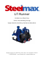
1
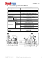
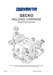
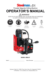
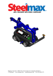
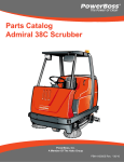
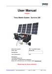
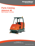
Li’l Runner
Portable Four Wheel Drive
Friction Drive Welding Carriage
Model: SM-WC-LR (120V) or SM-WC-LR-230 (230 V)
Steelmax Tools LLC 6200 S Troy Circle, Suite 110 Centennial, CO 80111
1-87STEELMAX - www.steelmax.com - [email protected]
SM-WC-LR
Table of Contents
I.
INTENDED USE ........................................................................................................ 3
II.
WC-LR PROPERTIES ............................................................................................... 3
III.
TECHNICAL SPECIFICATION SWC-8 ...................................................................... 4
IV.
WORK PREPARATION. ............................................................................................ 6
V.
STARTING UP........................................................................................................... 7
VI.
SAFETY..................................................................................................................... 8
VII.
GENERAL DESIGN. .................................................................................................. 9
VIII.
CONTROL PANEL MESSAGES ...............................................................................12
IX.
PARTS LIST AND EXPLODED DRAWINGS ............................................................13
X.
EC DECLARATION OF CONFORMITY ....................................................................20
XI.
MACHINE TEST CERTIFICATE ...............................................................................21
XII.
WARRANTY CARD ..................................................................................................22
SM-WC-LR 10/2011
Welding Carriage Operating Instructions
2
SM-WC-LR
I.
Intended use
The Li’l Runner is designed to transport various types of MIG/MAG welding torches with
diameters of 5/8” – 7/8” (16-22 mm). The Li’l Runner is intended to perform continuous
welds.
Caution: The Li’l Runner is not intended to be used overhead.
Mounting of MIG/MAG welding torches with chuck diameters larger than 5/8”-7/8”
(16-22 mm) is not recommended.
Torch cables should be supported.
Max weight of torch cables is 17lbs (8kg) for horizontal operations and 13lbs
(6kg) for vertical.
Max torch overhang beyond the carriage’s end 2 ¾” (70mm).
II.
WC-LR properties
1.
Lightweight and compact design.
2.
Permanent magnet traction.
3.
On/off magnet level allows for easier set up and adjustment to work piece.
4.
Maintenance-free four-wheel drive.
5.
Self locking chassis.
6.
Travel speed control.
7.
Quick clamping Torch Holder mechanism for different types of MIG/MAG torches.
8.
Precise torch adjustment.
9.
An automatic arc on/off feature.
10.
Power feed of 120V or 230V from mains.
11.
Easy to use.
SM-WC-LR 10/2011
Welding Carriage Operating Instructions
3
SM-WC-LR
III.
Technical specification SWC-8
Power supply
120-230V / 50-60Hz
Welding position
Vertical / Horizontal
Material thickness
4mm (0.16") minimum
Chassis to material clearance
Travel mechanism
Up-Down
4 mm (0.16")
4 rubber wheels
Equipped with permanent magnet block
2-Guide rollers
100N (vertical) (22.5 lbs, 10.2 kg);150N
(horizontal) (37.5 lbs, 15.3 kg)
35 mm (1.4")
Left-Right
35mm (1.4")
Tracking method
Pulling force
Slide Unit
Adjustment
Guide roller adjustment
Switch
Power supply On/Off
Switch
Start Left, Stop, Start Right
Horizontal speed
0-1000 mm/min (39.4"/min)
Vertical speed
0-1000 mm/min (39.4" /min)
240 (L)x258 (W)x253 (H), 9.4" (L) x 10.2" (W)
x 10" (H)
8kg, 17.6 lbs.
Control panel
Knob
Dimensions
Weight
SM-WC-LR 10/2011
100 mm (2.9")
Welding Carriage Operating Instructions
4
SM-WC-LR
Changing from English (Imperial) to Metric Measurement Units.
Unscrew 4 screws holding front
panel and take it out.
This is unit selection header JP1.
Remove this jumper to set
imperial units.
Put the jumper on the gold-pin
header to set metric units.
After modification you can check the current unit system in start-up mode of the carriage. If
the configuration jumper is removed from the unit selection header JP1, after lamp test will
appear USA on the display (displayed speed value is imperial (inch/min)), otherwise on the
display will appear EUr (displayed speed value is metric (cm/min)).
SM-WC-LR 10/2011
Welding Carriage Operating Instructions
5
SM-WC-LR
IV.
Work preparation.
1. Make sure that the wheels are not deformed and the silicone tires are clean.
2. Make sure that power switch is in OFF position, direction switch in central position –
STOP, and magnet block lever is toggled off (left position).
3. Inspect power supply cable for damage. Repair or replace if needed.
4. Plug the power supply cable into the Power Supply.
5. Clamp the torch into the Torch Holder.
6. Connect the Arc Contactor Cable to the welder. The Arc Contactor Cable has two
pairs of color coded wire. These wires will replace the trigger switch on the welding
gun which initiates the wire feeder and weld contactor. A contact closure is used
between like color wires and two guns can be controlled from one carriage.
Connections will vary depending on the manufacturer of the welding equipment.
Please see the below drawings for pin position, and consult your welding equipment
manufacturer for details on the necessary connectors. Adjust Guide arm distance
(Front Guide arm moved out about 3/8” (10 mm) less than Rear Guide). This will
cause the carriage to run in a crab like fashion and keep the carriage in constant
contact with the guiding structure.
7. Toggle the magnet block lever on (right position) – increases magnetic force to a work
surface.
8. Set wanted position of the torch using knobs located on Vertical Guide and Horizontal
Guide.
SM-WC-LR 10/2011
Welding Carriage Operating Instructions
6
SM-WC-LR
V.
Starting up
1. Make sure that all Work preparation steps were followed according to the instructions
and are not causing any danger to personnel.
2. Plug the power supply cable into the line power.
3. Toggle Power Switch (located inside handle on back of machine) into ON position.
On the LED display “888” figure should be shown.
4. After a short while on LED display “EUR” or “USA” should be displayed (depending
on the voltage 230V/120V which the carriage is supplied.
5. After digits appear on the display the speed should be adjusted using the speed
knob, for EUR in cm/min. and for USA in inches/min.
6. Switch the ARC CONTROL SWITCH to the OFF Position.
CAUTION: If the ARC CONTROL SWITCH is in the ON position, the arc will
initiate immediately upon selecting the travel direction.
7. Choose desired travel direction using the Travel Direction Switch. On the display the
speed will be shown – it may differ from adjusted as it depends on the Carriage load.
See the maximum loads in technical specifications.
8. Revise the travel speed adequately to the appropriate welding process conditions.
SM-WC-LR 10/2011
Welding Carriage Operating Instructions
7
SM-WC-LR
VI.
SAFETY.
All setting, handling and repair duties of the Carriage may only be carried out by
trained personnel.
1. Read the User’s Manual before using the machine and follow the instructions.
2. The machine is not waterproof. Work in damp conditions may cause damage to machine
or injuries.
3. Inspect the rubber tires on the Drive Wheels for damage, sand and chips.
4. Inspect the Bottom Plate for any foreign objects.
5. Ensure the magnet is switched ON prior to welding.
6. Carry and place the carriage only when the Magnet Block is switched off. Carry only by
handle (do not hold Bottom Plate – it may cause fingers injury).
7. Always place the Carriage on clean surfaces.
8. Do not connect the power until the Power Switch is in the “OFF” position.
9. Always use the original power cable or a factory supplied replacement.
10. Torch hoses should be suspended above the Carriage to decrease applied load.
11. When welding vertically and/or in vertical position use safety cords which will prevent the
carriage from falling and causing injury.
12. Do not leave the machine unattended, especially during welding.
13. Do not force the Carriage to stop by hand. Always use STOP setting.
14. Do not take off the Drive Wheels Guard as the heat from welding could damage the tires.
15. Do not stand or walk underneath the machine.
16. Any assembly and disassembly of parts should only be performed when power supply is
disconnected.
17. The carriage should be removed from working area and locked away in secure place
when not in use.
SM-WC-LR 10/2011
Welding Carriage Operating Instructions
8
SM-WC-LR
VII. General design.
The Li’l Runner welding carriage features a versatile and ergonomically correct design which
allows easy access to control elements, and ease of transport to the work piece.
It consists of: Drive Unit integrated with the Controller, Guide Assembly, Torch
Adjustment and Torch Holder.
Drive unit – a 16W gear motor is a part of the Drive Unit, which drives four high temperature
resistant silicone wheels through a worm gear transmission. It is powered with 120V/230V
depending on its version.
The Magnetic Block with powerful permanent magnets located on the bottom of the Carriage
delivers proper grip to metal surfaces. Intensity of a magnetic field is reduced by toggling the
Magnet Block Switch to OFF position, which makes maneuvering easier when placing on the
work piece. The Torch Holder is located in the Torch Adjustment Assembly which allows
precise adjustment in vertical and/or horizontal axis. The machine enables electric arc
ignition for a given travel direction - the cable socket for that feature is located on a main
panel of the Carriage.
SM-WC-LR 10/2011
Welding Carriage Operating Instructions
9
SM-WC-LR
1. Drive Unit with Control Panel
2. Cross Slide Torch Adjustment
3. Guide Arms
4. Torch Holder
5. Power Supply
6. Arc Ignition
7. Magnet Block Lever
8. On/off power switch
SM-WC-LR 10/2011
Welding Carriage Operating Instructions
10
SM-WC-LR
Control Panel
P1
3-digit LED display
P2
ARC CONTROL SWITCH ON/OFF/TEST
P3
Speed adjustment knob
P4
Travel direction switch (Left-Stop-Right)
SM-WC-LR 10/2011
Welding Carriage Operating Instructions
11
SM-WC-LR
VIII. Signification of messages displayed on the Control
Panel
Message Description
Solution
88.8
O.K.
Lamp test – test of display’s digits.
If some of the LED segments are not lit it Contact service to investigate the
means that there is a problem with the malfunction.
display.
USA
The configuration type or actual speed O.K.
value is given in “inches/min”.
EUr
The set type or actual speed value is O.K.
given in “cm/min”.
ErS
Travel direction switch error.
1. The Travel Direction Switch is activated 1. Set the travel direction switch to
middle position.
during starting up of the carriage.
2. If displayed during a welding operation 2. Replace the faulty
it means that there is a malfunction of the Contact the service.
Travel Direction Switch.
crL
switch.
Motor power cut-off activated.
In some cases it may appear when the
carriage stops suddenly and this message
appears on the display.
1.
Check if any elements
around the Carriage are jamming
or obstructing the Wheels.
2.
Check the weight and
position of the welding hoses.
3.
Check the carriage in idle
state (no load applied to the
carriage).
If message still appears on the
display , please call for service.
SM-WC-LR 10/2011
Welding Carriage Operating Instructions
12
SM-WC-LR
IX. Parts List and Exploded Drawings
ITEM
WOZ-0466-24-20-00-0
Steelmax Li'l Runner /230V
WOZ-0466-24-00-00-0
Steelmax Li'l Runner /115V
PART NUMBER
1
WOZ-0466-11-00-00-0
2
ZSP-0466-03-00-00-0
3
UCW-0466-04-00-00-0
3.1
ZRZ-0466-04-01-00-0
3.2
TLJ-0419-04-02-03-0
3.3
RKJ-000036
4
PLY-0466-05-00-00-0
5
WSP-0466-07-00-00-0
6
RKJ-0466-08-00-00-0
7
SRB-000083
8
SRB-000114
9
SRB-000075
10
PDK-000018
11
TBL-0466-15-00-01-0
12
NIT-000010
13
GLK-0466-12-00-00-0
14
DZW-0419-01-04-13-0
15
KUL-0466-13-00-00-0
16
PNL-0466-02-02-00-1
17
WKR-000092
18
WKR-000048
19
NKL-0466-15-00-02-0
20
PDK-000021
22
UCW-0476-06-00-00-0
22.1 ZCS-0476-06-01-00-0
23*
ZST-0466-25-00-00-0
23.1* PWD-0466-18-00-00-0
23*
ZST-0466-25-00-00-0
23.1* PWD-0466-16-00-00-0
23.2* KBL-0466-17-00-00-0
23.3* KLC-000007
23.4* INS-0239-55-00-00-2
* Not shown on drawing
SM-WC-LR 10/2011
VERSION
2060
2063
2065
2092
2067
2069
2071
2142
2144
2637
2073
2109
2491
2119
DESCRIPTION
DRIVE SYSTEM ASSY
CROSS SLIDES ASSY
TORCH HOLDING ASSY
TORCH CLAMP ASSY
INSULATION SLEEVE
HANDLEVER GN 300-45-M6-32-SW,
TORCH PLATE COMPLATE
SLIDE BRACKET
HANDLE
HEX SOCKET BOLT M5x16
HEX. SOCKET BOLT M6x20
HEX SOCKET BOLT M5 x 10
WASHER 5.3
NAME PLATE Li'l Runner by Steelmax
ROUND HEAD RIVET 2x6
HANDLE KNOB
LEVER
BALL LEVEL
CONTROL PANEL ASSEMBLY
SOCKET BUTTON HEAD CAP SCREW M4x10
SOCKET SET SCREW M5 x 6
LOGO LABEL "STEELMAX"
ROUND WASHER 6,4
LOW TORCH HOLDING ASSY
CLAMPING BLOCKS
EQUIPMENT SET
POWER CORD 230V
EQUIPMENT SET
POWER CORD 115V
CONTROL CABEL START-STOP
HEX. WRENCH S=4
OPERATORS MANUAL
Welding Carriage Operating Instructions
Q-TY
1
1
1
1
1
1
1
1
1
4
4
8
8
1
4
1
1
1
1
4
1
1
4
1
1
1
1
1
1
1
1
13
SM-WC-LR
SM-WC-LR 10/2011
Welding Carriage Operating Instructions
14
SM-WC-LR
WOZ-0466-11-00-00-0
ITEM
1.1
1.2
1.3
1.4
1.5
1.6
1.7
1.8
1.9
PART NUMBER
ZSP-0466-01-00-00-0
OBD-0466-02-00-00-0
PRW-0466-06-00-00-0
OSL-0466-09-00-00-0
SRB-0466-10-00-00-0
WKR-000091
WKR-000136
SRB-000278
PRS-000266
SM-WC-LR 10/2011
DRIVE SYSTEM ASSY
VERSION
2074
2490
2076
2077
DESCRIPTION
DRIVE SYSTEM
CONTROLLER HOUSING COMPLATE
FOLLOWER ASSEMBLY
WHEEL GUARD
FOLLOWER SCREW
SOCKET BUTTON HEAD CAP SCREW M4x8
SCR, M5 x 16 FHSCS
EYE BOLT M6,
SEAL O-RING 173x3
Welding Carriage Operating Instructions
Q-TY
1
1
2
1
2
3
4
2
1
15
SM-WC-LR
ZSP-0466-01-00-00-0
ITEM
1.1.1
1.1.2
1.1.3
1.1.4
1.1.5
1.1.6
1.1.6.1
1.1.7
1.1.8
1.1.9
1.1.10
1.1.11
1.1.12
1.1.13
1.1.14
1.1.15
1.1.16
1.1.17
1.1.18
1.1.19
1.1.20
1.1.21
1.1.22
1.1.23
1.1.25
1.1.26
1.1.27
PART NUMBER
VERSION
KRP-0466-01-01-00-1
WLK-0466-01-02-00-0
WLK-0466-01-03-00-0
BLO-0466-01-04-00-0
KOL-0466-01-05-00-0
MTR-0466-01-06-00-0
SLN-0466-01-06-10-0
KOL-0466-01-07-00-0
KOL-0466-01-08-00-0
ZSP-0466-01-09-00-0
PDK-0466-01-10-00-0
KOL-0456-01-05-00-0
PDK-000164
TLJ-000088
LOZ-000038
WPS-000027
PRS-000018
PRS-000005
SRB-000082
SRB-000061
WKR-000092
WKR-000136
WKR-000434
PDK-000108
PDK-000017
PDK-000060
NKR-000031
SM-WC-LR 10/2011
DRIVE SYSTEM
2078
2079
2080
DESCRIPTION
FRAME
FRONT DRIVE SHAFT ASSY
BACK DRIVE SHAFT ASSY
MAGNET BLOCK ASSEMBLY
INDIRECT GEAR WHEEL ASSY z30
MOTOR ASSEMBLY
MOTOR
DRIVE WHEEL
BEVEL GEAR z30
LEVER ASSEMBLY
SPACER WASHER
INTERMEDIATE GEAR ASSY
ROUND WASHER 12x18x1
SALFE-LUBRICATING BRUSHUNG FLANGE
BEARING 6001 ZZ
WOODRUFF KEY 3x5x13
INTERNAL RETAINING RING 28W
EXTERNAL RETAINING RING 15z
HEX. SOCKET BOLT M5x14
HEX SOCKET BOLT-M4X10
SOCKET BUTTON HEAD CAP SCREW M4x10
SCR, M5 x 16 FHSCS
FHSCS M4x20
ROUND WASHER 4,3
ROUND WASHER 5,3
SPRING WASHER 4,3
NUT M4 SHORT
Welding Carriage Operating Instructions
Q-TY
1
1
1
1
1
1
1
4
1
1
4
2
2
1
4
1
4
2
3
1
4
8
1
7
3
2
2
16
SM-WC-LR
SM-WC-LR 10/2011
Welding Carriage Operating Instructions
17
SM-WC-LR
OBD-0466-02-00-00-0
CONTROLLER HOUSING COMPLATE
ITEM
PART NUMBER
VERSION
1.2.1
1.2.2
1.2.3
1.2.4
1.2.5
1.2.6
1.2.7
1.2.8
1.2.9
1.2.10
1.2.12
1.2.13
1.2.14
1.2.15
1.2.16
1.2.17
1.2.18
1.2.19*
1.2.20*
PKR-0466-02-01-00-0
MDL-0466-02-03-00-0
PLY-0466-02-08-00-0
WZK-0466-02-05-00-0
WZK-0466-02-04-00-0
NKR-000120
PDK-000098
PDK-000165
OSL-000036
PNK-000026
PDK-000060
NKR-000013
PDK-000058
WKR-000152
WKR-000427
WKR-000428
WKR-000414
WZK-0466-02-06-00-0
WZK-0466-02-07-00-0
2082
DESCRIPTION
CONTROLLER HOUSING COVER
POWER SUPPLY ELECTRONIC CONTROLLER ASSY
INSULEITING PLATE
IGNITION SOCKET WIRE SET
POWER SOCKET WIRE SET
SAFETY NUT
SILICONES WASHER 20x15,
LOCKING WASHER 12/19
LEVER KEY COVER
LEVER KEY, 641 H/3
SPRING WASHER 4,3
HEX NUT M4
WASHER,LOCK,INTERNAL STAR M3
SCREW M4 x 16
CROSS RECESSED SCREW M3x8
CROSS RECESSED SCREW M3x8
LOTTED PAN HEAD MACHINE SCREWS M3x8
PANEL WIRE SET
POWER WIRE SET
Q-TY
1
1
1
1
1
1
1
1
1
1
2
2
4
1
6
4
1
1
1
* Not shown on drawing
SM-WC-LR 10/2011
Welding Carriage Operating Instructions
18
SM-WC-LR
PNL-0466-02-02-00-1
ITEM
16.1
16.1.1
16.2
16.3
16.4
16.5
16.6
16.7
16.8
16.9
16.10
PART NUMBER
MSK-0466-02-02-10-1
NKL-0466-15-00-03-1
STR-0466-02-02-02-0
PKT-000028
WZK-0466-02-02-01-0
WZK-0466-02-02-04-0
WKR-000181
PDK-000058
WZK-0466-02-02-05-0
PRS-000095
USZ-0466-02-02-03-0
SM-WC-LR 10/2011
PANEL ASSEMBLY
VERSION
2639
DESCRIPTION
PANEL PLATE ASSY
PANEL PLATE LABEL
ELECTRONIC CONTROLLER
POTENTIOMETER KNOB
POTENTIOMETER WIRE SET
IGNITION WIRE SET
CROSS RECESSED SCREW M3x6
WASHER,LOCK,INTERNAL STAR M3
DIRECTION OF MOTION WIRE SET
O-RING 12x2
PANEL PLATE SEAL
Welding Carriage Operating Instructions
Q-TY
1
1
1
1
1
1
4
4
1
1
1
19
X.
EC DECLARATION OF CONFORMITY
Declaration of compatibility
We
PROMOTECH Ltd.
Elewatorska Street 23/1
15-620 Bialystok, Poland
declare with full responsibility that product:
Li'l Runner Welding Carriage
which the declaration applies to is in accordance with the following standard(s)
placed below:
EN 50144-1, EN 55014 and satisfies safety regulations of guidelines: 2004/108/EC,
2006/95/EC, 2006/42/EC
Bialystok, 2011-10-05
________________________
Prezes
SM-WC-LR 10/2011
Welding Carriage Operating Instructions
20
XI.
MACHINE TEST CERTIFICATE
Machine control card
□ SM-WC-LR
□ SM-WC-LR -230
Serial No.
_______________________
Date of test:
_______________________
Electric test results:
Test
Result
Test with sinusoidal voltage
of 1000 V and frequency 50 Hz
Resistance of the protective circuit [Ω]
The above-mentioned product meets the requirements of safe usage as prescribed in standard IEC-745
Name of tester ____________________
Quality Control ____________________
SM-WC-LR 10/2011
Welding Carriage Operating Instructions
21
SM-WC-LR
XII. WARRANTY CARD
WARRANTY CARD No.............
Steelmax Tools LLC in the name of Manufacturer warrants the Drilling Machine to be
free of defects in material and workmanship under normal use for a period of twelve months
from date of original sale to the end user.
This warranty does not cover cutters, damage or wear arises from misuse, accident,
tempering or any other causes not related to defects in workmanship or material.
Date of Production .......................................... Serial No ..............................................
Quality Control: ..............................................................................................................
Date of Purchase: ..........................................................................................................
Signature of Seller…………………………………………………………………………….
Steelmax Tools LLC 6200 S Troy Circle, Suite 110 Centennial, CO 80111
1-87STEELMAX - www.steelmax.com - [email protected]
22