1
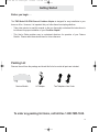
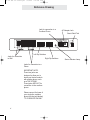
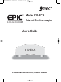
ECA for PDF v13 070903.qxd
7/9/2003
3:30 PM
Page 2
Model 810-ECA
External Cordless Adapter
User’s Guide
810-ECA
Please read before using feature module.
ECA for PDF v13 070903.qxd
7/9/2003
3:30 PM
Page 3
Getting Started
Getting Started
Congratulations! You’ve purchased a TMC Model 810-ECA External Cordless
Adapter that meets the highest standards for quality and convenience in the
Small Office/Home Office environment. To get the most from your Feature
Module, please take time to read this guide thoroughly.
IMPORTANT SAFETY INSTRUCTIONS
When using your telephone equipment, basic safety precautions should always
be followed to reduce the risk of fire, electric shock and injury to persons, including the following:
1. Do not use this product near water, for example, near a bath tub, wash bowl,
kitchen sink, or laundry tub, in a wet basement, or near a swimming pool.
2. Avoid using a telephone (other than a cordless type) during an electrical
storm. There may be a remote risk of electric shock from lightning.
3. Do not use the telephone to report a gas leak in the vicinity of the leak.
4. Use only the power cord and batteries indicated in this manual. Do not dispose of batteries in a fire. They may explode. Check with local codes for possible special disposal instructions.
5.
! Use only the class 2 power adapter 12VDC 500 mA.
SAVE THESE INSTRUCTIONS
i
ECA for PDF v13 070903.qxd
7/9/2003
3:30 PM
Page 4
Getting Started
Before you begin . . .
The TMC Model 810-ECA External Cordless Adapter is designed for easy installation in your
home or office. However, it is important that you follow these few simple guidelines:
-
Take a few minutes to read this manual so that you thoroughly understand the instructions to
be followed for proper installation of your Cordless Adapter.
-
This User’s Guide provides easy to understand directions for operation of your Feature
Module. Please retain these instructions for future reference.
Packing List
Remove the unit from the package and check this list to be certain all parts are included:
Feature Module
AC Adapter
Two Telephone Line Cords
To order any packing list items, call toll-free 1-800-TMC-1638.
ii
ECA for PDF v13 070903.qxd
7/9/2003
3:30 PM
Page 6
Table of Contents
Getting Started . . . . . . . . . . . . . . . . . . . . . . . . . . . . . . . . . . . . . . . . . . . . . .i
Reference Drawing . . . . . . . . . . . . . . . . . . . . . . . . . . . . . . . . . . . . . . . . . . .v
Section 1 - Installing Your External Cordless Adapter . . . . . . . . . . . . . .1-6
Step 1: Connect Line Cords . . . . . . . . . . . . . . . . . . . . . . . . . . . . . . .2
Step 2: Connect Telephone to Adapter . . . . . . . . . . . . . . . . . . . . . . .3
Step 3: Set Left DIP Switches to Proper Postions . . . . . . . . . . . . . .4
Step 4: Set Right DIP Switches to Proper Postions . . . . . . . . . . . . .5
Step 5: Connect Power Cord . . . . . . . . . . . . . . . . . . . . . . . . . . . . . .6
Section 2 - Using Your External Cordless Adapter . . . . . . . . . . . . . . . .7-15
Capabilities of your External Cordless Adapter . . . . . . . . . . . . . . . . .8
Important Points to Note . . . . . . . . . . . . . . . . . . . . . . . . . . . . . . . . . .9
Making a Call . . . . . . . . . . . . . . . . . . . . . . . . . . . . . . . . . . . . . . . . . .10
Answering a Call . . . . . . . . . . . . . . . . . . . . . . . . . . . . . . . . . . . . . . . .11
Using the Flash Button . . . . . . . . . . . . . . . . . . . . . . . . . . . . . . . . . . .12
Conferencing Two Outside Lines . . . . . . . . . . . . . . . . . . . . . . . . . . .13
Making and Answering Intercom Calls . . . . . . . . . . . . . . . . . . . . . . .14
Making Pages . . . . . . . . . . . . . . . . . . . . . . . . . . . . . . . . . . . . . . . . . .15
Section 3 - Additional Information . . . . . . . . . . . . . . . . . . . . . . . . . . . . . .17-21
Troubleshooting Guide . . . . . . . . . . . . . . . . . . . . . . . . . . . . . . . . . . .18
Warranty Information . . . . . . . . . . . . . . . . . . . . . . . . . . . . . . . . . . . . .19
FCC Information . . . . . . . . . . . . . . . . . . . . . . . . . . . . . . . . . . . . . . . .20
iv
ECA for PDF v13 070903.qxd
7/9/2003
3:30 PM
Page 7
Reference Drawing
Jack for connection to a
Cordless Phone
AC Adapter Jack
Strain Relief Tab
Left Dip Switches
Jacks for connection
to Wall
Right Dip Switches
Jacks for connection to a
Phone
IMPORTANT NOTE:
These two jacks are
designed to allow you to
share your feature module
with another phone, such
as a TMC ET4000.
These jacks ARE NOT for
connection to the cordless
phone.
Please connect the base of
your single-line cordless
phone into the jack labeled
“TO CORDLESS PHONE.”
v
Status Indicator Lamp
ECA for PDF v13 070903.qxd
7/9/2003
3:30 PM
Page 8
Installing Your External Cordless Adapter
Section
Page
2
Step 1: Connect Line Cords
3
Step 2: Connect Telephone to
Adapter
4
Step 3: Set Left DIP Switches
to Proper Positions
5
Step 4: Set Right DIP Switches
to Proper Positions
6
Step 5: Connect Power Cord
1
Installing
Your
External
Cordless
Adapter
1
ECA for PDF v13 070903.qxd
7/9/2003
3:30 PM
Page 9
Installing Your External Cordless Adapter
Step 1: Connect Line Cords
L1/L2
1 Connect First Line Cord
Connect one end of a long telephone line cord
to the jack on the back of the feature module
labeled L1/L2. Connect the other end to the
jack(s) labeled Lines 1 & 2 either:
Lines
1&2
directly to the wall jack if it is a two-line RJ14
jack
OR
to a two-line coupler (not provided) if you have
two single-line RJ11 jacks for lines 1 and 2.
Then connect the two cords of the coupler to
the corresponding wall jacks. Two-line couplers are available many places, for example
Radio Shack (part #279-401).
L1/L2
Line 1
Line 2
2 Connect Second Line Cord
Connect one end of a long telephone line cord
to the jack on the back of the feature module
labeled L3/L4. Connect the other end to the
jack(s) labeled Lines 3 & 4 in the same manner
as described in the previous step.
NOTE: If you wish to plug in the module to a
jack that is already in use, unplug the existing
device from the wall jacks, connect both of the
line cords to the module as shown, and then
plug the device into the jacks on the module
labeled “TO PHONE.”
2
L3/L4
ECA for PDF v13 070903.qxd
7/9/2003
3:30 PM
Page 10
Installing Your Cordless Phone Adapter
Step 2: Connect Telephone to Adapter
1 Install Cordless Telephone
Please follow the installation instructions that
came with your cordless telephone.
Note that TMC Corporation does not manufacture cordless telephones. The Cordless Phone
Adapter has been designed to be compatible
with any standard single-line telephone.
2 Connect Cordless Phone Base to
Adapter
Connect one end of the telephone line cord
that came with your cordless phone to the jack
in the cordless phone base as instructed in the
installation instructions that came with your
cordless phone, and plug the other end into the
jack on the External Cordless Adapter labeled
“To Cordless Phone.”
Note that you can use any single line device
with your Cordless Phone Adapter; it need not
be a cordless telephone. It is called a “External
Cordless Adapter” because most people use it
to provide a cordless extension for their
System.
Plug line cord
from telephone
to this jack on
the rear of the
feature module
3
ECA for PDF v13 070903.qxd
7/9/2003
3:30 PM
Page 11
Installing Your External Cordless Adapter
Step 3: Set Left DIP Switches to Proper Positions
Set Switches 1-2
The setting of these two DIP switches
determines the ringer setting for line 1.
Please refer to the drawing at the right to
determine how to set the DIP switches for
line 1.
Ringer ON
Ringer OFF
Set Switches 3-8
The setting of these six DIP switches
determines the line and ringer settings for
lines 2, 3, and 4.
Please refer to the drawing at right for
instructions on setting each line. Note that
the drawing illustrates setting DIP switches 3-4 for setting line 2. Set DIP switches
5-6 in the same manner to set line 3, and
set DIP switches 7-8 in the same manner
to set line 4.
4
Ringer ON
Ringer OFF
Line
UNCONNECTED
ECA for PDF v13 070903.qxd
7/9/2003
3:30 PM
Page 12
Installing Your External Cordless Adapter
Step 4: Set Right DIP Switches to Proper Positions
Set Switches 1-4
The setting of these four DIP switches
determines what station number your
External Cordless Adapter will be set as.
You may choose any station number from
12 to 26. Note that you may not set your
External Cordless Adapter as station #11.
Also please note that you must not assign
your External Cordless Adapter the same
station number as any of your phones or
other feature modules. IT MUST BE
ASSIGNED ITS OWN UNIQUE STATION
NUMBER.
Refer to the drawing at right to determine
how to set the DIP switches for the station
number you choose.
Stn 19
Stn 12
Stn 20
Stn 13
Stn 21
Stn 14
Stn 22
Stn 15
Stn 23
Stn 16
Stn 24
Stn 17
Stn 25
Stn 18
Stn 26
Set Switch 5
The setting of this DIP switch determines
flash length.
Set the switch in the up position for normal
length flashes (approximately 700 milliseconds), or place the switch in the down
position for short flashes (approximately
200 milliseconds).
Set switch 5 in the up position to set
this External Cordless Adapter to
normal length flashes
Set switch 5 in the down position to
set this External Cordless Adapter to
short flashes
In most environments it is best to leave
this switch in the up position, for normal
length flashes. If you find that calls are
dropping when you use the flash button,
then try setting the switch in the down
position.
5
ECA for PDF v13 070903.qxd
7/9/2003
3:30 PM
Page 13
Installing Your Cordless Phone Adapter
Step 5: Connect Power Cord
1 Connect Power Cord to Module
Plug the AC power cord into the adapter jack at
the rear of the Feature Module. Thread the
power cord around the strain relief tab.
2 Connect Power Cord to Wall Outlet
Plug the AC adapter into an electrical outlet not
controlled by a wall switch.
3 Make Sure that Status Indicator Lamp
is Blinking
This indicates that the feature module is properly connected to electrical power.
6
ECA for PDF v13 070903.qxd
7/9/2003
3:30 PM
Page 14
Using Your Cordless Phone Adapter
Section
Page
8
Capabilities of your External
Cordless Adapter
9
Important Points to Note
10
Making a Call
11
Answering a Call
12
Using the Flash Button
13
Conferencing Two Outside
Lines
14
Making and Answering
Intercom Calls
15
Making Pages
2
Using Your
External
Cordless
Adapter
7
ECA for PDF v13 070903.qxd
7/9/2003
3:30 PM
Page 15
Using Your External Cordless Adapter
Capabilities of your Cordless Phone Adapter
Features of your External Cordless
Adapter
•
•
•
•
•
•
•
•
Make Calls on Any Line
Answer Calls on Any Line
Place Calls on Hold
Conference Two Outside Lines
Make Intercom Calls
Answer Intercom Calls
Make Pages
Make an Intercom Call or Page to
another Station while You Have a
Call on Hold
• Transfer a Call to Another Station
• Receive Calls Transferred from other
Stations
• If your cordless phone has a caller ID
display, it will indicate which line an
incoming call is ringing on.
• If you subscribe to caller ID and your
cordless phone has a caller ID display, it will display the caller ID information
• If you are engaged in a call and a
call is ringing on another line, you will
hear one, two, three, or four beeps in
your ear to indicate which line the
call is coming in on.
8
You may connect up to 15 External Cordless
Adapters to your System. Connect each one to
a separate cordless telephone, and assign each
one a station number from 12 to 26 (See page
5).
Once you connect your cordless phone to the
External Cordless Adapter, you will enjoy all the
features listed on this page.
ECA for PDF v13 070903.qxd
7/9/2003
3:30 PM
Page 16
Using Your External Cordless Adapter
Important Points to Note
You must attach your External Cordless Adapter to all lines that you wish to
access from your cordless telephone.
You must connect your External Cordless Adapter to line 1 for it to function.
This feature module is called a “External Cordless Adapter” because most people use it to provide a cordless extension to their System. However, it works
with any standard single-line telephone.
You may connect up to 15 External Cordless Adapters to your System. Connect
each one to a separate cordless telephone and assign each one a different
extension number from 12 to 26.
Your External Cordless Adapter will not work with private lines.
The External Cordless Adapter is compatible with features such as call waiting,
Centrex, and other central office features that require the use of the Flash button. However, please remember that if you want to make a switchhook flash,
you must press the Flash button, followed by “0.”
9
ECA for PDF v13 070903.qxd
7/9/2003
3:30 PM
Page 17
Using Your External Cordless Adapter
Making a Call
To make a call on any available line:
1 Go off-hook with your telephone. With
most cordless phones, this is done by
the pressing of a button labeled “Phone”
or “On.” Note that you will now be
hearing the internal dial tone.
2 Dial “9” on your telephone.
This will seize the first available line, and
you should now be hearing the regular
dial tone.
When you go off-hook at your cordless telephone, you will hear the internal dial tone.
You may then select a line to make your outside
call.
To seize the first available line, dial “9” on your
telephone’s dialpad. You will be connected to
line 1, if it is free. If line 1 is in use, you will be
connected to line 2, and so on.
3 Dial your call normally.
To make a call on a particular line:
1 Go off-hook with your telephone. With
most cordless phones, this is done by
the pressing of a button labeled “Phone”
or “On.” Note that you will now be
hearing the internal dial tone.
2 Dial “81”, “82”, “83” or “84” on your telephone.
81 ...if you
82 ...if you
83 ...if you
84 ...if you
wish
wish
wish
wish
to
to
to
to
seize
seize
seize
seize
line
line
line
line
1
2
3
4
This will seize that particular line, and
you should now be hearing the regular
dial tone.
3 Dial your call normally.
10
If, however, you wish to make an outgoing call
on a particular line, dial “8”, followed by the corresponding number on the dialpad. For example, if you wish to make a call on line 3, dial “83”
on the dialpad. Note that if that particular line is
in use, you will not automatically be connected
to another line.
After you dial “9” or the particular number to
seize a line, you will hear the regular dial tone.
You may now dial your call in the normal manner.
Note: You can also use these steps to take a
call off of hold that has been put on hold by
another Station. Simply go off hook at your cordless phone (you should now be hearing the internal dial tone), and then dial “81” to take a call off
hold on line 1, or “82” to take a call off hold at line
2, and so on.
ECA for PDF v13 070903.qxd
7/9/2003
3:30 PM
Page 18
Using Your External Cordless Adapter
Answering a Call
To answer a call that is ringing at your
cordless telephone:
1 Go off-hook at your telephone. With
most cordless phones, this is done by
the pressing of a button labeled “Phone”
or “On.”
Note that this is exactly the same way
that you would answer a ringing call if
your cordless telephone were connected
directly to the line.
Note that if your cordless phone has
caller ID capability, the display will indicate which line the call is ringing on. The
display will read “L1:”, “L2:”, “L3:”, or
“L4:” and will also display the caller ID
info if you subscribe to the caller ID service on that line.
To answer a call that is not ringing at
your cordless telephone:
1 Go off-hook at your telephone. With
most cordless phones, this is done by
the pressing of a button labeled “Phone”
or “On.” Note that you will now be
hearing the internal dial tone.
2 Dial “81”, “82”, “83” or “84” on your telephone.
81 ...if you
82 ...if you
83 ...if you
84 ...if you
wish
wish
wish
wish
to
to
to
to
answer
answer
answer
answer
a
a
a
a
call
call
call
call
on
on
on
on
line
line
line
line
This will seize that particular line, and
you should now be speaking to the calling party.
1
2
3
4
When your cordless telephone is ringing, you
may answer the call by simply going off-hook at
that telephone. You will automatically be connected to the ringing line.
You may however wish to turn some or all of your
ringers OFF at your cordless phone (See page 4
for instructions on doing this).
If you wish to answer a particular line that you
hear ringing at another phone, but whose ringer
is OFF at your cordless phone, do the following:
Go off-hook at your telephone. Note that you
will now be hearing the internal dial tone.
To answer the ringing line, dial “8”, followed by
the corresponding number on the dialpad of your
cordless telephone.
IMPORTANT NOTE: If you are engaged in a call
on your cordless phone, and a call is ringing on
another line, you will hear one, two, three, or four
beeps in your ear to indicate which line the call
is ringing on.
If you wish to answer that call, you may hang up
your cordless phone, wait for your cordless
phone to start ringing, then go off hook to answer
the new call.
Or you may put your current call on hold by
pressing FLASH, then dial “81”, “82”, “83” or “84”
to answer the ringing line. When you wish to
return to your call on hold, hang up your cordless
phone, wait for your cordless phone to start ringing, then go off hook and you will be connected
to the original call.
11
ECA for PDF v13 070903.qxd
7/9/2003
3:30 PM
Page 19
Using Your External Cordless Adapter
Using the Flash button
To put a call on hold:
1 Press the FLASH button on your cordless
phone.
To take the call off of hold:
1 Press the FLASH button on your cordless
phone again.
Note that you can also take the call off of
hold at any other phone by simply seizing that line at the other telephone.
To make a switchhook flash:
1 Press the FLASH button on your cordless
The Flash button is used for placing calls on
hold, taking calls off of hold, and conferencing
two lines together, as well as the standard Flash
function of causing a switchhook flash.
To put a call on hold, simply press the Flash button on your cordless phone.
You can take the call of from hold at any system
or non-system telephone by seizing the line at
that phone. If you would like to take the call of
from hold at your cordless phone, simply press
Flash again.
IMPORTANT: If you would like to use the Flash
button to make a switchhook flash, press the
Flash button and then dial “0.”
phone.
2 Dial “0.”
12
This feature is used to activate services such as
Call Waiting or 3-Way Calling, or certain Centrex
features or other features that may be offered by
your Telephone Company.
ECA for PDF v13 070903.qxd
7/9/2003
3:30 PM
Page 20
Using Your External Cordless Adapter
Conferencing Two Outside Lines
To conference two outside lines:
1 Place your first call on hold by pressing
FLASH. Note that you will now be
hearing the internal dial tone.
2 Make or answer your second call. (See
pages 10 and 11, starting with step 2).
While having a conversation on one line, you
can make or answer a call on another line, then
connect both lines together to create a conference call.
To end the conference call, hang up your cordless phone and both parties will be disconnected.
3 Press FLASH again to conference the
two lines together.
4 To end a conference call, hang up.
Both parties will be disconnected.
13
ECA for PDF v13 070903.qxd
7/9/2003
3:30 PM
Page 21
Using Your External Cordless Adapter
Making and Answering Intercom Calls
To intercom another station:
1 Go off-hook with your telephone. With
most cordless phones, this is done by
the pressing of a button labeled “Phone”
or “On.” Note that you will now be
hearing the internal dial tone.
2 Dial “ ”, followed by a number from 11-
*
26, indicating the station you wish to
intercom.
3 After someone answers or you hear the
confirming tone, speak towards the telephone and talk.
4 To end the conversation, hang up your
cordless telephone as you normally
would.
To answer an intercom call to your
cordless telephone:
1 Go off-hook with your telephone. With
most cordless phones, this is done by
the pressing of a button labeled “Phone”
or “On.”
2 You will automatically be connected to the
ringing intercom call.
14
When you go off-hook at your cordless telephone, you will hear the internal dial tone.
You may then place an intercom call to any other
system telephone.
*
Simply dial “ ”, followed by the number of the
station you wish to intercom.
Note: If the intercom line is currently in use or
the called extension is set to DO NOT DISTURB,
you will not be able to place the intercom call.
Please also note that when you go off-hook at
your cordless telephone, you will hear the internal dial tone whether or not the intercom is currently in use.
When your cordless telephone is ringing
because someone is calling you on the intercom,
you may answer the intercom call by simply
going off-hook exactly the same as if you were
answering a call ringing on an outside line.
You will automatically be connected to the ringing intercom call.
ECA for PDF v13 070903.qxd
7/9/2003
3:30 PM
Page 22
Using Your External Cordless Adapter
Making Pages
To page another station:
1 Go off-hook with your telephone. With
most cordless phones, this is done by
the pressing of a button labeled “Phone”
or “On.” Note that you will now be
hearing the internal dial tone.
2 Press “#”, followed by a number from 1126, indicating the station you wish to
page.
3 After you hear the paging tone, speak
towards the telephone and talk.
4 To end the page, hang up your cordless
telephone as you normally would.
When you go off-hook at your cordless telephone, you will hear the internal dial tone.
You may then make an intercom page to any
other system telephone.
Simply dial “#”, followed by the number of the
station you wish to page.
Note: If the intercom line is currently in use or
the paged extension is set to DO NOT DISTURB, you will not be able to make the page.
Please also note that when you go off-hook at
your cordless telephone, you will hear the internal dial tone whether or not the intercom is currently in use.
To make an All Page:
1 Go off-hook with your telephone. With
most cordless phones, this is done by
the pressing of a button labeled “Phone”
or “On.” Note that you will now be
hearing the internal dial tone.
2 Press the “#” button twice.
3 After you hear the paging tone, speak
The All Page feature enables you to make
announcements through all of the other system
telephones.
When you make an All Page, your announcement, preceded by a double paging alert tone,
will be heard at all the phones that are not in use
and do not have their DO NOT DISTURB or
Page Block activated.
towards the telephone and talk.
4 To end the page, hang up your cordless
telephone as you normally would.
15
ECA for PDF v13 070903.qxd
7/9/2003
3:30 PM
Page 24
Additional Information
Section
Page
18
Troubleshooting Guide
19
Warranty Information
20
FCC Information
3
Additional
Information
17
ECA for PDF v13 070903.qxd
7/9/2003
3:30 PM
Page 25
Additional Information
Troubleshooting Guide
If you are having difficulty with your External Cordless Adapter, DO NOT RETURN IT!
You may find your problem and solution listed below. If not, call TMC’s toll-free customer support
line at 1-800-TMC-1638, and an expert will walk you through your problem. You may also use this
toll-free line if you ever have a question that is not answered in your User’s Guide.
The Feature Module does not
work.
Check all connections and make sure that they are securely in place. Make sure that the AC adapter is plugged into a
jack not controlled by a wall switch. Check to make sure
that the status indicator lamp is blinking. If it is not,
unplug and then replug the AC power cord. If the status indicator still fails to start blinking, check your wall jack by plugging another device such as a lamp into the outlet to make
sure that the outlet is working properly.
The Feature Module is connected properly, but still does
not work.
The problem may be with the telephone wiring:
If possible, check your jack wiring by testing a telephone at
the jack where you installed the Feature Module. If this
standard telephone does not work, then local telephone
company lines or your own wiring may be causing the problem.
The problem may be with your cordless telephone:
Check to make sure that your cordless phone is working
properly. Plug it into another line jack to be sure. Make sure
that it is connected properly to the Adapter (see page 3).
When you connect your
External Cordless Adapter, the
station is not assigned as you
wish, or some other settings
are not as you wish.
The problem may be with the DIP Switch settings on the
back of the External Cordless Adapter:
Please confirm that the DIP switches on the back of the
External Cordless Adapter are set properly. Refer to pages
4 and 5 for instructions on setting them properly.
Other problems.
Make sure that you have followed the instructions in this
User’s Guide. If you continue to have problems, call TMC’s
toll-free customer support line at 1-800-TMC-1638.
18
ECA for PDF v13 070903.qxd
7/9/2003
3:30 PM
Page 26
Additional Information
Warranty Information
TWO-YEAR LIMITED WARRANTY
We urge you to complete the Warranty Registration Form enclosed with your product and send it in. This
will enable you receive future updates and product information from TMC.
What does your warranty cover?
Any defect in material or workmanship.
For how long after the original purchase?
Two years.
What will TMC do?
We will repair or, at our option, replace your TMC product at no charge to you. If we repair your product,
we may use new or reconditioned replacement parts. If we choose to replace your product, we may
replace it with a new or reconditioned one of the same or of a similar design. The exchange unit will be
warranted for the remainder of your product’s original two-year warranty period.
How do you make a warranty claim?
Call TMC to receive a Return Authorization Number. Properly pack your unit, and write the Return
Authorization Number on the outside of the box. Do not include the cords etc. which were originally provided with the product unless specifically requested to do so by the TMC representative. Include in the
package a copy of the sales receipt or other proof of the date of original purchase. Also print your name,
address, phone number, and a detailed description of the defect or operating problem. Ship the product
standard UPS or equivalent (you must prepay all shipping costs) to:
TMC Corporation, Product Service Center, 2540 Route 130, Unit 117, Cranbury, NJ 08512
After repairing or replacing your TMC product, we will ship it back to you at no cost to you.
What does this warranty not cover?
- Customer instruction. Your User’s Guide provides information regarding installation, operating
instructions and user controls. For additional information, ask your dealer.
- Defects resulting from accidents, alterations, unauthorized repair, failure to follow instructions, misuse, neglect, fire, floods, lightning, and acts of God.
- Product which has been modified or incorporated into other products.
- Product purchased or serviced outside the U.S.
We do not warrant your TMC products to be compatible with any particular telephone equipment or party
line, key telephone systems, or more sophisticated customer premises switching systems.
Neither do we warrant your TMC products to function properly in all user environments, since wiring
and other factors can affect performance.
Limitations and Exclusions
This warranty is the only one we offer for your TMC product, and it sets forth all our responsibilities
regarding your TMC product. There are no other express warranties.
TMC CORPORATION SHALL NOT BE LIABLE FOR INCIDENTAL OR CONSEQUENTIAL DAMAGES
RESULTING FROM THE USE OF THIS PRODUCT, OR ARISING OUT OF ANY BREACH OF THIS
WARRANTY. ALL EXPRESS AND IMPLIED WARRANTIES, INCLUDING THE WARRANTIES OF
MERCHANTABILITY AND FITNESS FOR A PARTICULAR PURPOSE, ARE LIMITED TO THE APPLICABLE WARRANTY PERIOD SET FORTH ABOVE.
Some states do not allow the exclusion or limitation of incidental or consequential damages, or limitations
on how long an implied warranty lasts, so the above exclusions or limitations may not apply to you. This
warranty gives you specific legal rights and you may also have other rights which vary from state to state.
19
ECA for PDF v13 070903.qxd
7/9/2003
3:30 PM
Page 27
Additional Information
FCC Information
This equipment complies with Part 68 of the FCC rules. On the base of this equipment is a label
that contains, among other information, the FCC registration number and ringer equivalence number (REN) for this equipment. If requested, this information must be provided to the telephone
company.
The FCC requires that you connect your feature module to the telephone network through a modular telephone outlet or jack, which must comply with FCC part 68 rules.The modular telephone
outlet or jack to which your feature module must be connected is a USOC RJ11C or RJ14C.
The REN is used to determine the quantity of devices which may be connected to the telephone
line. The REN for your feature module is 0.1. Excessive RENs on the telephone line may result
in the devices not ringing in response to an incoming call. In most, but not all areas, the sum of
the RENs should not exceed five (5). To be certain of the number of devices that may be connected to the line, as determined by the total RENs, contact the telephone company to determine
the maximum REN for the calling area.
If the terminal equipment feature module causes harm to the telephone network, the telephone
company will notify you in advance that temporary discontinuance of service may be required. But
if advance notice isn’t practical, the telephone company will notify you as soon as possible. Also,
you will be advised of your right to file a complaint with the FCC if you believe it is necessary.
The telephone company may make changes in its facilities, equipment, operations or procedures
that could affect the operation of the equipment. If this happens, the telephone company will provide advance notice in order for you to make the necessary modifications in order to maintain uninterrupted service.
If trouble is experienced with your feature module, please contact TMC Corporation at 1-800TMC-1638 for repair and/or warranty information. If the trouble is causing harm to the telephone
network, the telephone company may request you remove the equipment from the network until
the problem is resolved. Do not attempt to repair or modify this equipment. Please contact TMC
Corporation for information on obtaining service for this product.
This equipment cannot be used on public coin service provided by the telephone company.
Connection to Party Line Service is subject to state tariffs. (Contact the state public utility commission, public service commission or corporation commission for information.)
20
ECA for PDF v13 070903.qxd
7/9/2003
3:30 PM
Page 28
Additional Information
FCC Information (Continued)
Warning: Your feature module generates and uses R.F. (Radio Frequency) energy. It complies
with FCC Part 15, Subpart J for Class B computing devices. If not used in strict accordance with
manufacturer’s instructions, the feature module can cause interference to radio and/or television
reception. The rules with which it must comply afford reasonable protection against interference
when used in most locations. However, there can be no guarantee that such interference will not
occur in a particular installation. In the event that such interference does occur, make sure this
unit is the source of interference. To do so, disconnect the feature module from the telephone line
and unplug it from the AC wall outlet. If interference is still present, this unit is not the source of
R.F. If this does stop the interference, proceed as follows:
1. Reorient or relocate the receiving antenna on the unit experiencing interference.
2. Move the feature module away from the unit experiencing interference.
3. Plug the unit experiencing interference into a different AC wall outlet.
If necessary, consult your dealer or an experienced radio/television technician for additional suggestions. The following booklet, prepared by the Federal Communications Commission, may be
helpful:
“How to Identify and Resolve Radio-Television Interference Problems”
The booklet is available from the U.S. Government Printing Office, Washington, DC 20402, Stock
No. 004-000-0345-4.
21