1
K150
USER’S MANUAL
Kurzweil Music Systems, Inc.
Waltham, MA
June 1986 version
KMSI P/N: 91002501
Copyright (C) 1986 Kurzweil Music Systems, Inc.
Table of Contents
Preface . . . . . . . . . . . . . . . . . . . . . . . . . 6
How To Use This Manual . . . . . . . . . . . . . 6
Introduction . . . . . . . . . . . . .
Introduction . . . . . . . . . . .
Programs, Regions, and Layers .
The Modifiers . . . . . . . .
The Editors . . . . . . . . .
The Built-In Programs. . . .
Getting Started . . . . . . . . . .
Selecting Between Programs
.
.
.
.
.
.
.
.
.
.
.
.
.
.
.
.
.
.
.
.
.
.
.
.
.
.
.
.
.
.
.
.
.
.
.
.
.
.
.
.
.
.
.
.
.
.
.
.
.
.
.
.
.
.
.
.
.
.
.
.
.
.
.
.
1-1
1-1
1-1
1-1
1-2
1-3
1-3
1-4
Using the K150X . . . . . . . . . . . .
Communicating with the K150X. .
The Buttons on the Front Panel
The Display . . . . . . . . . . . .
.
.
.
.
.
.
.
.
.
.
.
.
.
.
.
.
.
.
.
.
.
.
.
.
.
.
.
.
2-1
2-1
2-1
2-3
The Channel Editor . . . . . . . . . . . . . . . . . 3-1
Using the Channel Editor . . . . . . . . . . . . 3-1
Channel Editor Hints . . . . . . . . . . . . . . . 3-1
The Tuning Editor . . . . .
Using the Tuning Editor
Master Tuning . . . . .
Transposition . . . . . .
Intonation. . . . . . . .
Reference Key . . . . .
.
.
.
.
.
.
.
.
.
.
.
.
.
.
.
.
.
.
.
.
.
.
.
.
.
.
.
.
.
.
.
.
.
.
.
.
.
.
.
.
.
.
.
.
.
.
.
.
.
.
.
.
.
.
.
.
.
.
.
.
.
.
.
.
.
.
.
.
.
.
.
.
.
.
.
.
.
.
4-1
4-1
4-1
4-1
4-2
4-2
The MIDI Editor. . . . .
Using the MIDI Editor
MIDI Mode. . . . . .
MIDI Channel . . . .
Mod Wheel . . . . . .
Velocity Map . . . . .
Loudness Map . . . .
Program List . . . . .
.
.
.
.
.
.
.
.
.
.
.
.
.
.
.
.
.
.
.
.
.
.
.
.
.
.
.
.
.
.
.
.
.
.
.
.
.
.
.
.
.
.
.
.
.
.
.
.
.
.
.
.
.
.
.
.
.
.
.
.
.
.
.
.
.
.
.
.
.
.
.
.
.
.
.
.
.
.
.
.
.
.
.
.
.
.
.
.
.
.
.
.
.
.
.
.
.
.
.
.
.
.
.
.
5-1
5-1
5-1
5-2
5-2
5-2
5-3
5-4
The Program Editor . . . . . . . . . . .
Using the Program Editor . . . . . .
Selecting and Editing Programs .
F1, F2, and F3 in the Program Editor
Pitch Wheel and Key-Pressure Bend .
Soft Pedal. . . . . . . . . . . . . . .
Left and Right Split Points . . . . . .
Left and Right Region Balances . . .
.
.
.
.
.
.
.
.
.
.
.
.
.
.
.
.
.
.
.
.
.
.
.
.
.
.
.
.
.
.
.
.
.
.
.
.
.
.
.
.
.
.
.
.
.
.
.
.
6-1
6-1
6-1
6-2
6-3
6-4
6-4
6-5
.
.
.
.
.
.
.
.
The Region Editor . . . . . . . . . . . . . . . . . . 7-1
Using the Region Editor . . . . . . . . . . . . . 7-1
F1, F2, and F3 in the Region Editor . . . . . . . 7-1
The Layer Editor . . . . . . . . . . . . .
Using the Layer Editor . . . . . . . . .
Selecting and Editing Layers . . .
F1, F2, and F3 in the Layer Editor
Creating and Deleting Layers . . .
Voice . . . . . . . . . . . . . . . . . .
Tuning . . . . . . . . . . . . . . . . .
Transposition . . . . . . . . . . . . . .
.
.
.
.
.
.
.
.
.
.
.
.
.
.
.
.
.
.
.
.
.
.
.
.
.
.
.
.
.
.
.
.
.
.
.
.
.
.
.
.
8-1
8-1
8-1
8-2
8-2
8-2
8-3
8-3
Timbre Mode . . . .
Timbre-Shift Value .
Timbre-Select . . . .
Timbre-Level . . . .
Balance Mode. . . .
Balance Level . . . .
Pitch Bend Mode . .
Chorus Mode . . . .
Vibrato Mode . . . .
Equalizer Number. .
.
.
.
.
.
.
.
.
.
.
.
.
.
.
.
.
.
.
.
.
.
.
.
.
.
.
.
.
.
.
.
.
.
.
.
.
.
.
.
.
.
.
.
.
.
.
.
.
.
.
.
.
.
.
.
.
.
.
.
.
.
.
.
.
.
.
.
.
.
.
.
.
.
.
.
.
.
.
.
.
.
.
.
.
.
.
.
.
.
.
.
.
.
.
.
.
.
.
.
.
.
.
.
.
.
.
.
.
.
.
.
.
.
.
.
.
.
.
.
.
.
.
.
.
.
.
.
.
.
.
8-3
8-4
8-4
8-5
8-5
8-6
8-6
8-6
8-7
8-7
The Chorus Editor . . . . . . . . . . .
Using the Chorus Editor . . . . . .
Notes . . . . . . . . . . . . . . . .
Detune . . . . . . . . . . . . . . .
Delay . . . . . . . . . . . . . . . .
Decay . . . . . . . . . . . . . . . .
Chorus Editor Assignable Controls .
Chorus Editor Hints. . . . . . . . .
.
.
.
.
.
.
.
.
.
.
.
.
.
.
.
.
.
.
.
.
.
.
.
.
.
.
.
.
.
.
.
.
.
.
.
.
.
.
.
.
.
.
.
.
.
.
.
.
.
.
.
.
.
.
.
.
9-1
9-1
9-1
9-2
9-2
9-2
9-2
9-3
The Vibrato Editor . . . . . . .
Using the Vibrato Editor . .
Triangle or Square . . . . .
Depth . . . . . . . . . . . .
Rate . . . . . . . . . . . . .
Symmetry . . . . . . . . .
Delay . . . . . . . . . . . .
Vibrato Assignable Controls
.
.
.
.
.
.
.
.
.
.
.
.
.
.
.
.
.
.
.
.
.
.
.
.
.
.
.
.
.
.
.
.
.
.
.
.
.
.
.
.
.
.
.
.
.
.
.
.
.
.
.
.
.
.
.
.
.
.
.
.
.
.
.
.
.
.
.
.
.
.
.
.
.
.
.
.
.
.
.
.
.
.
.
.
.
.
.
.
.
.
.
.
.
.
.
.
.
.
.
.
10-1
10-1
10-1
10-2
10-2
10-3
10-3
10-4
The Equalizer Editor. . . . . . . . . . . . . . . . 11-1
Using the Equalizer Editor . . . . . . . . . . . 11-1
The Control Editor . . . . . . . . . . .
F1, F2, and F3 in the Control Editor
Using the Control Editor . . . . . .
How Assignment is Done . . . . . .
Assignable Controls and Switches .
.
.
.
.
.
.
.
.
.
.
.
.
.
.
.
.
.
.
.
.
.
.
.
.
.
.
.
.
.
.
12-1
12-1
12-1
12-2
12-3
The Miscellaneous Editor . . . . . . . . . . . .
Using the MISC Editor . . . . . . . . . . . .
The Program List Editor . . . . . . . . . . .
Using the Program List Editor . . . . . .
F1, F2, and F3 in the Program List Editor
Intonation Table Editor . . . . . . . . . . . .
Using the Intonation Editor . . . . . . .
Velocity Map Editor . . . . . . . . . . . . .
Using the Velocity Map Editor . . . . .
.
.
.
.
.
.
.
.
.
13-1
13-1
13-1
13-1
13-1
13-2
13-2
13-3
13-3
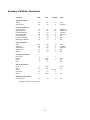
Summary of Editable Parameters . . . . . . . . . . A-1
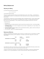
Battery Replacement . . . . . . . . . . . . . . . . . B-1
Replacing the Battery . . . . . . . . . . . . . . . B-1
Replacement Batteries . . . . . . . . . . . . . . B-1
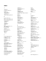
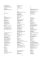
INDEX . . . . . . . . . . . . . . . . . . . . . . . . I-1
Preface
How To Use This Manual
This manual assumes some knowledge of music theory and terminology, and familiarity with some concepts of electronic
sound generation, the Musical Instrument Digital Interface (MIDI) standard, and other recent advances in music creation and
performing.
Chapter 1 will give you a brief overview of the Kurzweil Model K150X Expander (K150X), and show you how to connect it
to your MIDI controller and start making music right away. SThe manual assumes that your MIDI controller is a piano
keyboard-like controller. However, the K150X will work with any controller which produces standard MIDI signals.
After reading Chapter 1, you should be able to play the K150X’s built-in sounds, and begin to suspect that you can do much
more.
Chapter 2 describes using the K150X in-depth, and gives you an overview of the editors and how to use them. After this
chapter, you should be able to read the chapters on individual editors as you need them.
Chapters 3 through 13 are on individual editors. Within each editor chapter, everything you can do with that editor is
documented, with examples and references to other chapters as needed.
Appendix A is a summary of editable parameters from all the editors.
Appendix B, Battery Replacement, describes how to change the battery in the K150X.
i
Introduction
Introduction
The Kurzweil Model K150X Expander (K150X) has built-in programs you can play directly, and editors with which you can
modify these programs to create an enormous range of sounds and playing/performance options.
In most synthesizers, the sound begins with a simple electronic waveform that is then filtered and shaped to produce the final
tone. The Kurzweil K150X Expander is also a synthesizer. However, instead of starting off with a simple electronic
waveform, the K150X starts with a computer model of an acoustically rich instrumental sound. These models, which we call
voices, are created by a Contoured Sound Model, which produces the rich, authentic tones for which Kurzweil Music
Systems has become famous.
Programs, Regions, and Layers
In addition to the voices, the K150X offers many sound-modifying resources. By using these resources, we are able to
change a basic voice to create a great variety of new tone colors. The resources are referred to as modifiers. A voice,
together with its associate modifiers, is called a layer.
With the K150X, you can combine layers to form a composite tone color, and then assign that combination of layers to a
region. A region is one group of keys into which the K150X divides the incoming MIDI keyboard information. The K150X
enables you to set up one, two, or three keyboard regions.
A complete keyboard setup is called a program. The program tells where the regions are, which layers are in each region,
and which voice and modifier values are in each layer. The programs are numbered from 0 to 255. A given program may be
selected by the K150X’s front panel, or by a MIDI program change command.
Thus, programs are built up like the branches of a tree. The program is the tree itself, the regions are parts of the tree’s
"trunk", and the layers are "branches" that are attached to the trunk. To continue the analogy, you can think of the K150X as
a "forest" of up to 255 trees. The size of the forest is fixed by the amount of memory in the K150X. You can have up to 255
"trees," but if you build up big trees with a lot of "branches" (that is, a complex program with a lot of layers), it will take
more space in the memory than smaller trees with fewer layers, and you will be able to fit fewer than the maximum of 255 in
your "forest" of programs.
The K150X allows you to build up a program of one, two, or three regions, each of which may have up to seven layers. In
working on your programs, you may set up, change, or remove just a layer, a region of layers, or an entire program.
The Voices
Many voices are built in to every K150X. A list of the resident voices is given in Chapter 8 of this manual. In addition,
every K150X contains voice expansion slots into which supplied voice block integrated circuits are inserted. Additional
expansion slots are also supplied so that you can add more voice block integrated circuits later on.
All voices are instantly available for playing. That is, there is no waiting time to play any of the voices that you have
installed within the instrument.
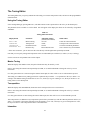
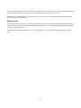
The Modifiers
Modifiers change a voice, or change the manner in which the voice responds to MIDI control signals. Modifiers may be
applied at the layer level, program level, or be instrument-wide. A modifier which is applied at the layer level affects only
that layer, a modifier applied at the program level affects all layers in all regions defined by the program, and an instrumentwide modifier affects all the programs in the K150.
Instrument-wide modifiers include:
•
•
MIDI assignments
Master transposition, tuning, and intonation
1-1
•
Keyboard response adjustments
Program-wide modifiers include:
•
•
•
•
•
Controller ranges
Sizes and balances of regions
Chorusing
Vibrato
Equalization
Layer-wide modifiers include.
•
•
•
•
Voice selection
Voice modification
Layer transposition and tuning
Layer balancing
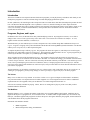
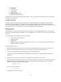
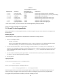
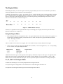
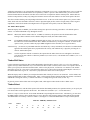
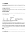
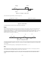
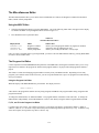
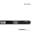
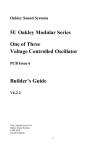
Figure 1-1 shows pictorially how you might look at a single program, its relationship to its regions, layers, editors, and its
relationship to the other programs.
Program 16
Program 15
Chorusing
Region 1
Vibrato
Region 2
Program 17
Equalizer
Region 3
Layer 1
Layer 2
Layer 1
Layer 2
Layer 1
Layer 2
...
...
...
Layer 7
Layer 7
Layer 7
Figure 1-1. Sample Program.
The Editors
The modifiers of the K150X are accessible through its editors. By using the editors to create your own programs from
scratch, or to modify the built-in programs, you can create an enormous range of new and different programs. They, in turn,
may be stored in the K150X, or on an external cassette tape.
The following editors are available:
1.
2.
3.
4.
(MIDI) Channel editor
Tuning editor
MIDI Mode editor
Program editor
1-2
5.
6.
7.
8.
9.
10.
11.
Region editor
Layer editor
Chorusing editor
Vibrato editor
Equalizer editor
(MIDI) Assignment editor
Miscellaneous functions editor
All changes that you make while editing take effect instantly. Thus, you can play the keyboard while you’re editing to hear
the changes as you make them.
The Built-In Programs
The built-in programs are popular playing configurations of conventional instruments, or highlight sound modification
features of the K150X. Program #1, for instance, is a piano. Program #2 combines a piano with a bass: the lowest two
octaves of the keyboard sound like a bass, while the rest of the keyboard remains a piano. You can select and play these and
many other programs, as soon as the K150X is connected to a MIDI controller and an amplifier.
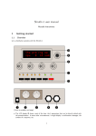
Getting Started
The K150X allows a myriad of connections between itself and other devices through the MIDI interface. We’ll describe a
simple setup with the K150X acting as a MIDI receiver from a MIDI controller, which we’ll assume to be a piano keyboardlike device.
To set up the K150X and one MIDI controller, you will need:
•
•
•
•
110V or 220V AC electrical power
A MIDI controller
A MIDI cable
Headphones with a ¼-inch stereo phone plug (mono or stereo), or a ¼-inch mono phone plug connected to an
amplifier and speaker combination.
Follow this general procedure:
1.
The K150X will operate on either 110V or 220V AC power, and indicates on the rear panel which kind of power it is
currently set up for. Make sure the K150X is set for the voltage in your location before turning it on.
2.
Connect one end of the MIDI cable to the MIDI OUT jack on the MIDI controller.
3.
Connect the other end of the MIDI cable to the MIDI IN jack on the K150X. No other jacks should be used in this
application.
4.
Plug the power cord in between the K150X’s AC LINE IN connector and the AC power source.
5.
Turn on the K150X by pressing the power switch on the lower right side of the front panel. This insures that when your
MIDI controller is powered up the K150X will receive any setup information which might be sent by your MIDI
controller. After a few seconds, the display will read
KURZWEIL 150X
for a few seconds, and then read
C1 P1 PIANO
meaning that the K150X is ready to go.
1-3
6.
Turn on the amplifier, and plug the ¼-inch phone plug into the AUDIO OUT jack on the rear panel of the K150X, and/or
plug the headphones into the headphone jack on the front panel of the K150X.
7.
Adjust the volume control on the front panel of the K150X to a low, but audible level, and press a keyboard key. You
should now be getting an acoustic piano sound.
When using headphones, the volume control should be set to a comfortable listening level. However, when using an external
amplifier or speaker, best results are obtained when the volume level is set as loud as your amplifier will allow without
distorting.
Selecting Between Programs
The display should currently read:
C1 P1 PIANO
meaning that Program number 1, with name "PIANO", is active and assigned to MIDI Channel 1. Press INCR, and the
display should read:
C1 P2 ABS/PNO
You should now be able to play Program number 2, which has an acoustic bass voice in the lower part of the keyboard and a
piano in the upper part of the keyboard. To return to Program number 1, press DECR.
You can use INCR and DECR to step through all the currently existing programs and play them. You can also jump between
non-sequentially numbered programs by entering the number of the desired program using the numbered buttons, and
pressing ENTER. You are now ready learn more about the K150X and what it does.
1-4
Using the K150X
In this chapter you’ll be introduced to the button-pads of the K150X, and briefed on what the individual buttons do and how
they work. This will lead into a discussion of the editors and how to use them.
Communicating with the K150X
All your interaction with the K150X is through the front panel button-pad and display.
Using the buttons on the front panel, you tell the K150X what to do. The K150X gives information back to you visually
through its display, and audibly through its audio output, enabling you to listen to changes as you make them.
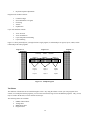
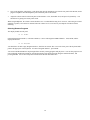
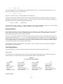
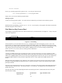
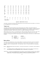
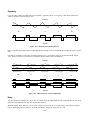
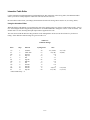
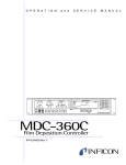
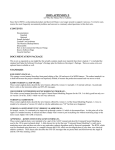
The Buttons on the Front Panel
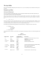
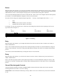
From here on, we’re going to divide the buttons on the front panel into 2 halves: the left button-pad and the right button-pad,
as shown in Figure 2-1. Each of these halves is used to perform different functions.
CHANNEL
TUNE
MIDI
LEFT
CENTER
RIGHT
F1
F2
F3
1
2
3
4
5
6
7
8
9
NO
YES
-
0
PROG
REGION
LAYER
SAVE
CANCEL
UNDO
CHORUS
VIB
EQ
INCR
DECR
CLR
CTRLS
MISC
NEXT
PREV
EDIT
left button-pad
ENTR
right button-pad
Figure 2-1. The Front Panel Buttons.
The Left Buttonpad
The left button-pad is used to select parameters to edit, and to perform various other operations while editing. Although there
are only 12 keys, they perform many operations by doing different things depending on what you’re up to and how you got
there. Sequences of previous button selections can make a difference in what a button does. (Don’t worry, the display helps
you keep track of your button selections.)
On the Buttons. Written on the buttons are names or abbreviations for what they do if you press them directly (i.e. if you
haven’t just pressed the EDIT button), as shown in Table 2-1.
Table 2-1
Left Button-pad Buttons
Button
F1
F2
F3
SAVE
CANC
UNDO
INCR
Meaning
Function #1
Function *2
Function #3
save
cancel
undo
increment
What It Does
changes - we’ll get back to them
save the current changes
cancel all changes since the last time save was pressed
undoes (re-does) the last value change
increment the value (i.e. raise it)
2-1
DECR
CLR
NEXT
PREV
EDIT
decrement
clear
next
previous
edit
decrement the value (i.e. lower it)
clear the value (usually to 0)
advance to the next parameter (i.e. step forward through the options)
go back to the last parameter (i.e. step backward through the options)
special button, used in sequence with the others above
Above the Buttons. Written above the buttons are abbreviations for the K150X’s different editors. The EDIT button gives
you access to the K150X’s editors. You access the editors by pressing the EDIT button first, and then the button below the
abbreviation. (If you’ve ever used a scientific calculator, in which keys have different meanings depending on whether
you’ve pushed the "function" key, this works the same way.) For instance, pressing EDIT F2 selects TUNE, the Master
Tuning Editor. The editors are summarized in Table 2-2.
Table 2-2
Button Sequences for Editors
Word or Abbreviation
Above Button
CHAN
TUNE
MIDI
PROG
REGION
LAYER
CHORUS
VIB
EQ
CONTROLS
MISC
Abbreviation
For
Channel
Tune
MIDI
Program
Region
Layer
Chorus
Vibrato
Equalization
Controls
Miscellaneous
Buttons Sequence
to Press
EDIT F1
EDIT F2
EDIT F3
EDIT SAVE
EDIT QUIT
EDIT UNDO
EDIT INCR
EDIT DECR
EDIT CLR
EDIT NEXT
EXIT PREV
Meaning
Selects the Channel Assignment Editor
Accesses the Master Tune Editor
Selects the MIDI Editor
Accesses the Program Editor
Selects region to edit
Accesses the Layer Editor
Accesses the Chorus Editor
Accesses the Vibrato Editor
Accesses the Graphic Equalization Editor
Accesses the MIDI Control Editor
Accesses the Miscellaneous Editor
The Right Button-pad
There are numbers printed on most of the buttons of the right button-pad. You use these buttons to enter values after you’ve
selected parameters to change with the left button-pad. The new values don’t take effect until you press the ENTR button.
Three of the buttons, ENTR, 0, and -, have special meanings:
ENTR
You’ll be using the ENTR button often. Pressing ENTR means different things at different times:
•
•
enter a selected editor
indicate you’re finished entering a value; Use ENTR after entering a number to let the K150X know you’re
finished. If you’ve used a computer before, think of ENTR as the RETURN button of a computer when used in
this context. If nothing seems to be happening, try pressing the ENTR button. (Don’t worry, you can always
press undo to undo the change.)
0
The 0 button serves 2 different purposes:
• enters 0 for numeric values
• answers "Yes" to K150X questions (the sign button, - is "no".)
- (The sign button)
2-2
Pressing the sign button means different things at different times:
•
•
•
it starts entry of a negative number. When you intend to enter a negative number, press - first.
it steps through 4-way signs. Some K150X values can be positive (+), negative (-), starting positive (±), or
starting negative (-/+). Pressing - steps through these 4 values.
it answers "no" to K150X questions. ("No" is printed above the button.)
Left, Center, and Right
The words "LEFT, "CENTER", and "RIGHT" appear above the 1, 2, and 3 keys. These meanings are significant only in the
Region Editor. They allow you to quickly select which region of the keyboard you want to edit.
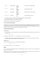
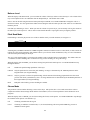
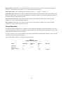
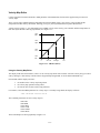
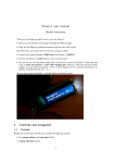
The Display
The K150X communicates back to you visually using the display, which is capable of displaying up to 16 alphabetic and/or
numeric characters. The display gives you the information concisely, using abbreviations and information Fields to show
you what’s happening. The location of a number or abbreviation within the display is important. It can be divided
approximately into 5 fields, as shown in Figure 2-2.
1
2
3
4
5
Figure 2-2. Fields of the K150X Display
When you’re using the Program, Region, or Layer Editors, the number of that program, region, or layer appears in Field 1.
Outside of these editors, Field 2 usually moves over into this field.
The name, or an abbreviation for the name of the parameter being edited appears in Field 2.
When applicable, the sign of the value in Field 4 appears in Field 3. This can be +, −, and sometimes ± or -/+.
The value for the parameter in Field 2 appears in Field 4.
An abbreviation for the units of the value in Field 4, when applicable, appear in Field 5. Table 2-3 shows the abbreviations
the K150X uses in Field 5 and their meanings:
Table 2-3
Units in the K150X Display
Abbreviation
C
ST
dB
ms
Hz
kHz
Unit
cents
semitone
decibels
milliseconds
Hertz
kiloHertz
Meaning
1 cent = 1/100 of a semitone
1/2 of a whole tone (50 cents)
a measurement of loudness
1 millisecond = 1/1000 of a second
cycles per second - frequency
Hertz x 1000
For example, consider the following displays:
2-3
C1.
TUNE
-58C
The Center Region, Layer #1 is being edited. The parameter being edited is TUNE (tuning), whose present value is -58C.
This layer is tuned down -58C (it is 58 cents flat).
P1
250 HZ
+5 dB
Program #1’s equalizer is given +5 dB of emphasis at the 250Hz point.
The display which appears when the K150X is turned on, showing the MIDI channel and program number currently active,
indicates that you are in the Channel Editor, the top-level editor. Any time you want to return to this editor, press EDIT F1.
The display will show the Channel and Program currently active:
C number P number
program-name
This is the K150X’s top-level display. C stands for CHANNEL and P stands for PROGRAM. From here, you can use INCR
and DECR to step through the Programs, or NEXT and PREV to step through the Channels.
Using the Editors
It is through the editors that you display and change parameters in the K150X. Press EDIT to indicate you want to select an
editor. Then select the editor you want by pushing the button below its abbreviation. For example, EDIT F1 selects the
Channel Editor while EDIT UNDO selects the Layer Editor.
Once you are in the editor, the display will identify the program, region, and/or layer that you are editing, the name of or an
abbreviation for the parameter (e.g., .V-DEPTH for vibrato depth) and the current editable value, which will be flashing. To
change a numeric value, simply enter the new value using the numeric button-pad and press ENTR, or use INCR and DECR
to step through the numbers. (Note that flashing stops when you start entering a new value.) The NEXT and PREV buttons
are used to step through the various parameters in that editor.
All changes that you make while editing take effect instantly. Thus, you can play the instrument while you are editing to
hear the changes as you make them.
The Editing Buttons
Once an editor has been selected, the buttons of the left button-pad take on the meanings printed on them.
F1, F2 and F3
These buttons are active only in certain editors, and have special functions which depend on the currently active editor, as
outlined in Table 2-4. These functions are discussed in detail the chapters on individual editors.
Table 2-4
F1, F2 and F3 in Various Editors
Editor
Channel
Program
Region
Layer (selecting)
Layer (using)
Controls
Program List (Misc)
F1
Read Cassette
Rename Program
Delete Region
Delete Layer
Change Layer (up)
Jump to Beginning of List
Jumps 16 Entries
F2
Memory Space
Copy Program
Copy Region
Copy Layer
Change Layer (down)
Jump to Chorus Controls
Insert Program
SAVE and CANC
2-4
F3
Delete Program
Replace Region
Insert Layer
Mute Other Layers
Jump to Vibrato Controls
Delete Program
The SAVE and CANC buttons can be used at any time during editing. SAVE will cause all changes that you have made to
be stored in the K150X’s non-volatile RAM memory. This memory is used to initialize the machine when it is turned on.
CANC will cancel all changes that you have made since the last time SAVE was pressed.
UNDO
If you are in the middle of a numeric entry (no flashing) UNDO cancels the entry (i.e., the display will begin flashing again).
Otherwise, UNDO cancels the last change that you made to the current parameter. Pushing UNDO again will re-do the
change. Thus, UNDO can be used to switch back and forth between two values.
INCR and DECR
These buttons can be used to increment and decrement the current parameter value or entry value. If you use them after
entering a value but before pushing ENTR they just increment and decrement the entered value. If the current parameter
value is displayed (flashing) then INCR and DECR will alter that value directly. For example, if the current value of Master
Tune is 20, pushing INCR is equivalent to pushing 2, 1, ENTR.
The INCR and DECR buttons will repeat at a rate of ten times a second if held down for more than one second.
CLR
If you are in the middle of making a numeric entry (flashing has stopped), CLR just sets the entry value to 0. Otherwise, it
sets the the current parameter value to 0 (the equivalent of pushing 0, ENTR ). For parameters for which 0 is not a legal
value, CLR sets the parameter to the lowest allowable value. For a parameter where a number is not a legal value, CLR sets
the parameter to the default value.
NEXT and PREV
These buttons allow you to step thru the parameters associated with the current editor. If you have started making a numeric
entry, but haven’t pressed ENTR, pressing NEXT or PREV completes the entry for you.
Like INCR and DECR, these buttons repeat if held down for more than one second, but at a slower rate (twice a second).
EDIT
In general, you can use EDIT Fn at any time to select a different editor. Press EDIT EDIT to return to the previous editor
you were in. Since each editor remembers what it was doing when you exited from it, you can bounce back and forth
between editors with little difficulty.
If you have started making a numeric entry, but haven’t pressed ENTR, pressing EDIT completes the entry for you.
To return from all editors, press EDIT and any key on the right button-pad. The display will show the CHANNEL and
PROGRAM number currently active:
C number P number program-name
This is the K150X’s Channel Editor display: C stands for CHANNEL and P stands for PROGRAM. From here, you can use
INCR and DECR to step through the Programs, or NEXT and PREV to step through the Channels.
2-5
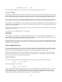
A Block Diagram of the K150X
Figure 2-3 shows the relationships between the various K150X parameters and modifiers, and how they interact to achieve a
certain result. Although reasonably complex, the diagram will become clearer as you become familiar with the K150X and
its operation. It is supplied here only for reference; you don’t need to study it in order to use the K150X.
(large, complex, hardly readable, original diagram not included)
Figure 2-3. The K150X Expander Effects Processing Chart.
2-6
The Channel Editor
The Channel Editor lets you assign programs to individual MIDI channels.
If the instrument is in Omni mode, changing the channel number in the Channel Editor also changes the basic MIDI channel
number. In addition, changing the channel will also change the currently selected program (see program editor below),
unless there is no program assigned to the channel or the currently selected program has been changed.
Using the Channel Editor
Enter the Channel Editor by pressing EDIT F1, and the display will show:
C xx P xxx
program name
Where Cxx is the currently active channel, and Pxxx is the currently active program number.
To change the channel, enter the new channel number with the numeric button-pad and press or use the NEXT and PREV
keys to step through the numbers 1 through 16. If a number greater than 16 is entered using the numeric keypad, the channel
number will be set to the previous channel number when ENTR is pressed.
To de-activate a channel, use CLEAR or 0 ENTR.
Channel Editor Hints
The Channel Editor will not allow you to assign a non-existent program to a channel. In particular, the INCR and DECR
keys will skip over non-existent program numbers.
3-1
The Tuning Editor
The Tuning Editor lets you specify instrument-wide tuning, set a master transposition value, and activate the programmable
intonation table.
Using the Tuning Editor
Select Tuning Editing by pressing EDIT F2. (The abbreviation TUNE is printed above the F2 key on the button-pad.)
The parameters shown in Table 4-1 can be edited. One will appear in the display; the others can be selected by using NEXT
and PREV.
Table 4-1
Tuning Editor Parameter
Display Reads
Parameter
MAST TUNE
TRANSPOSE
INTONATION
REFERENCE KEY
Master Tuning
Transposition
Intonation Switch
Reference key
Adjustable Values *
(use INCR and DECR)
±0-125C
±60ST
On/Off
Entire Musical Scale
What it Does
Tunes the entire instrument.
Transposes the entire instrument.
Switch for intonation parameters.
Sets a reference key for intonation.
* If the value is numeric, you can also enter the value directly with the right button-pad and press ENTR.
Note that you can specify tuning and transposition values for individual layers with the Layer Editor (see Layer Editing).
See the sections on each parameter later in this chapter.
Master Tuning
When the display reads MAST TUNE, the pitch of the K150X may be tuned by ±125C.
Enter a value using the numeric button-pad and press ENTR, or use INCR and DECR to change the value by 10 cent
increments.
If a value greater than 125 is entered using the numeric button-pad, the value will be set to 125 when ENTR is pressed.
This tuning is in addition to any tuning specified for a particular layer with the .TUNE parameter in the Layer Editor. For
example, if the Master Tuning for the K150X is set at +3C, and a layer is given a tuning of +2C, the layer will have a +5C
tuning relative to the natural pitch.
Transposition
When the display reads TRANSPOSE, the K150X can be transposed from 0 to ±6O semitones.
Enter a value using the numeric button-pad and press ENTR, or use INCR and DECR to change the value by 1 semitone
increments.
If a value greater than 60 is entered using the numeric button-pad, the value will be set to 60 when ENTR is pressed.
This transposition is in addition to any transposition specified for a particular layer with the .TRANS parameter in the Layer
Editor. For example, if the master transposition for the K150X is set at +3ST, and a layer is given a transposition of +2ST,
the layer will have a +5ST transposition relative to the natural tone.
Intonation
4-1
Used in conjunction with the Intonation Table Editor, which allows you to adjust the micro-tonal distance between individual
intervals, this parameter determines whether the values specified with that editor will be active or not.
When the display reads INTONATION, you can change the value of the switch. Use INCR and DECR to change the value
between off and on. The default is off.
Reference Key
Used in conjunction with the Intonation Table Editor, which allows you to adjust the micro-tonal distance between individual
intervals, this parameter allows you to specify which key you will be playing in so that the intervals will be properly adjusted
for that key. The default key is C.
When the display reads REFERENCE KEY, you can change the key. Use INCR and DECR to step through the musical
scale.
4-2
The MIDI Editor
With the MIDI Editor, you select settings which specify how the K150X will interpret its incoming MIDI signals.
Using the MIDI Editor
Enter the MIDI Editor by pressing EDIT F3. One of the two parameters shown in Table 5-1 will appear in the display; the
others may be accessed by pressing NEXT or PREV.
Table 5-1
MIDI Editor Parameters
Display Reads
Parameter
MIDI MODE
MIDI Mode
CHANNEL
MOD WHEEL
MIDI Channel
Modulation Wheel
VELOCITY MAP
LOUDNESS MAP
PROGRAM LIST
Velocity Map
Loudness Map
Program List
Adjustable Range *
(use INCR and DECR)
Omni
Poly
Multi
I - 16
Normal (0- 12 7)
Centered
0-7
0-7
Direct
1-32
33-64
65-96
97-128
1-64
65-128
1-128
What it Does
Selects the MIDI Mode
Selects the basic MIDI Channel
Selects the MIDI signal interpretation for the
modulation wheel signal
Selects one of the seven velocity maps
Selects one of the seven loudness maps
Selects the program list mapping from
controller to K150X.
* If the value is numeric, you can also enter the value with the right button-pad and press ENTR
MIDI Mode
About MIDI Modes
Information can be transmitted on 16 distinct channels in the MIDI interface. The K150X can respond in three ways to this
incoming information, with each of the ways having different interpretations and implications.
Omni Mode
The K150X will respond to incoming information on any of the 16 MIDI Channels.
This is the default mode.
Poly Mode
The K150X will respond to incoming information only on the specific channel currently specified
(the default is Channel 1).
Multi Mode
Individual programs of the K150X can be programmed to respond to different incoming channels.
Each MIDI channel can have a separate program number assigned. Multi Mode ignores the Omni
on/off message.
Selecting a MIDI Mode
Use INCR and DECR to step through the three choices.
5-1
MIDI Channel
The MIDI Channel parameter lets you select the basic MIDI channel. The default channel is Channel #1.
When the display shows CHANNEL you can select the Channel number. Enter the new channel number with the numeric
button-pad and press ENTR, or use the INCR and DECR keys to step through the numbers 1 through 16. If a number greater
than 16 is entered using the numeric keypad, the channel number will be set to the previous channel number when ENTR is
pressed.
Mod Wheel
Your controller’s modulation wheel may or may not be centered. You can select which way the K150X interprets the MIDI
signal coming from your modulation wheel.
When the display reads MOD WHEEL, you can use the INCR and DECR keys to select between "Normal" and "Centered."
In Normal mode, signals coming from the modulation wheel are given the values 0-127. In Centered mode, the values are
shifted down to be from -64 to +63, with 0 as the center point.
Velocity Map
The K150X contains 8 velocity maps, which determine how the key velocity signals coming from your MIDI controller will
be interpreted. These velocity maps allow you to get different response characteristics from your MIDI controller.
When the display reads VELOCITY MAP, select one of the velocity maps by pressing INCR or DECR, or enter a value from
0-7 directly with the numeric keypad, and press ENTR. The default velocity map is map #0, which is a linear mapping in
which increased MIDI values result in proportionally increased interpretations by your K150X. Although 7 different default
velocity maps are supplied, the maps themselves can be modified with the Velocity Map editor under the Miscellaneous
Editor. See the Miscellaneous Editor for more information.
5-2
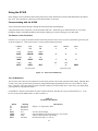
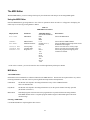
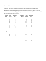
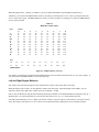
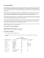
Loudness Map
The K150X contains 8 loudness maps, which determine how the key velocity signals coming from your MIDI controller will
be interpreted. These loudness maps allow you to get different volume characteristics from your MIDI controller.
When the display reads LOUDNESS MAP, select one of the velocity maps by pressing INCR or DECR, or enter a value
from 0-7 directly with the numeric keypad, and press ENTR. The default loudness map is map #0, which is a linear mapping
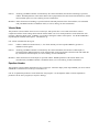
in which increased MIDI values result in proportionally increased volume.
The values of the 8 loudness maps are as follows:
Loudness
Map #
MIDI
Velocity
Attenuation
(dB)
Loudness
Map #
MIDI
Velocity
Attenuation
(dB)
0
0
32
48
84
110
127
26
21
17
7
3
0
4
0
28
74
96
116
127
64
54
12
8
3
0
1
0
26
32
48
84
115
127
48
26
21
17
6
3
0
5
0
32
64
96
24
18
12
6
2
0
10
32
48
112
127
48
30
21
17
6
0
6
0
32
64
96
127
30
20
10
5
0
3
0
64
96
127
48
12
5
0
7
0
32
64
96
127
36
24
12
3
0
5-3
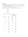
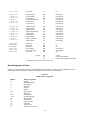
Program List
From your MIDI controller, you will be able to directly select only a limited subset of the 255 program numbers of the
K150X. The PROGRAM LIST parameter in the MIDI editor lets you select how your controller’s program setup numbers
will be mapped into the program numbers of the K150X.
This feature works in conjunction with the Program List Miscellaneous Editor, where you map the list entry numbers to
K150X program numbers. See the Miscellaneous Editor for more information.
When the display reads PROGRAM LIST, use INCR and DECR to select among the following choices:
Direct
1- 32
33- 64
65- 96
97-128
1- 64
65-128
1-128
The way that these choices are interpreted by the K150X is outlined in Table 5-2.
Table 5-2
Program List Modes
List Mode
MIDI #
Maps to ...
K150X #
Direct
0 - 127
program
1 - 128
1 - 128
0 - 127
list entry
1 - 128
1 - 64
0 - 63
64 - 127
list entry
1 - 64
1 - 64
65 - 128
0 - 63
64 - 127
list entry
65 - 128
65 - 128
1 - 32
0 - 31
32 - 63
64 - 95
96 - 127
list entry
1 - 32
1 - 32
1 - 32
1 - 32
33 - 64
0 - 31
32 - 63
64 - 95
96 - 127
list entry
33 - 64
33 - 64
33 - 64
33 - 64
65 - 96
0 - 31
32 - 63
64 - 95
96 - 127
list entry
65 - 96
65 - 96
65 - 96
65 - 96
97 - 128
0 - 31
32 - 63
64 - 95
96 - 127
list entry
97 - 128
97 - 128
97 - 128
97 - 128
5-4
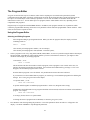
The Program Editor
Programs are the K150X’s top-level construct, under which everything else associated with a particular keyboard
configuration and sound quality is defined. Each program can divide the keyboard into three regions and each region can
have up to seven sound layers. Each sound layer specifies a voice as well as a number of modifiers which alter the
characteristics of the voice. You can define up to 255 programs, but the actual number can be less, depending on how
complicated each program is.
Programs may be assigned to individual MIDI channels. In addition, each program contains a set of parameters which
control the programmable chorusing effect and a set of parameters which control the programmable vibrato oscillator. These
effects are discussed in separate sections.
Using the Program Editor
Selecting and Editing Programs
1.
Select Program Editing by pressing EDIT SAVE. When you enter the program editor, the display will show
something similar to:
PROG 1
PIANO
• the currently selected program’s number (1 in our example),
• the currently selected program’s name (PIANO - an acoustic piano),
2.
Select a program to work on by using INCR, DECR, NEXT, PREV, or select it by number using the numeric button-pad
and press ENTR. Depending on what program numbers you select, and what their statuses are, you might see these
variations in the display as you change programs:
• An asterisk, *, as in:
PROG 1 *PIANO
This means that edits have been made to a built-in program, or that a program is user created. In this case, for
instance, the PIANO program has been modified. You can delete the modifications by pressing F1. The * will
disappear, and the built-in program will be restored.
Note that built-in programs cannot be deleted - only modifications made to them can be deleted.
If you wanted to save the modified built-in program, you could copy it to an undefined program before deleting the
changes. See Creating Programs later in this chapter.
• A question mark, ?, as in:
PROG 206 ?UNTITLED
A question mark designates an undefined program number. In this case, Program #206 is empty.
UNTITLED is the default name for any program which has not been named, and is not an indicator of an undefined
program. For example,
PROG 206 *UNTITLED
is not empty, because there is no question mark.
To change the name of program from UNTITLED, see Renaming Programs, below.
3.
Press ENTR to start choosing among the parameters. One of the parameters shown in Table 6-1 will appear in the
display. Use NEXT and PREV to step through the parameters.
6-1
Table 6-1
Program Editor Parameters
Display Reads
Parameter
.P-BEND
.K-BEND
.SFT-PDL
.L-SPLIT
.R-SPLIT
.L-BAL
.R-BAL
pitch wheel bend
key pressure bend
soft pedal
left split point
right split point
left region balance
right region balance
Adjustable Range *
(use INCR and DECR)
±60ST
±60ST
±30dB
C0-C9
C0-C9
±15dB
±15dB
What it Does
Sets the range and direction of the pitch bender.
Sets the range and direction of key pressure pitch bending.
Sets the range of the soft pedal.
Delineates the lower bound of the center region.
Delineates the upper bound of the center region.
Adjusts the volume of the left region.
Adjusts the volume of the right region.
* If the value is numeric, you can also enter the value with the right button-pad and press ENTR.
See the sections on each parameter later in this chapter.
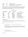
F1, F2, and F3 in the Program Editor
In the Program Editor, F1 initiates program renaming. F2 initiates program copying. and F3 deletes the current program, as
described below.
Renaming Programs
Undefined and user-created programs have the default name UNTITLED. To change the name:
1.
Press F1. The display will ask
RENAME PROGRAM?
Press 0 (yes) to continue the re-naming process, or press - to quit. If you press 0 (yes), the first letter of the current
name will start blinking. For instance, if the current name is UNTITLED, the U will start to blink.
2.
Press the INCR or DECR button. The letter will change to another character. For instance, the U in UNTITLED will
change to V or T, depending on whether you pressed INCR or DECR. Using these two buttons, you can select any of the
letters of the alphabet, the numbers 0 through 9, or the characters "/", "_", or "*". Choose the first character of the new
name in this way.
3.
To move to the next character position, press NEXT. Use INCR or DECR to repeat the process described in (2) above.
To return to a previous character position, press PREV.
4.
To exit, press F1.
Copying Programs
To copy the current program, press F2. The display will ask
COPY PROGRAM?
Press 0 (yes) to copy the program. The display will read:
COPY current-program number TO current-program number
Enter the program number you want the current program copied to, and press ENTR. Assuming the program number you
selected was empty, the program will be copied, and you will now be editing the program of the new program number.
If a program already existed under the number you selected, the display will read.
6-2
REPLACE PROGRAM?
Press 0 (yes), and the program will be replaced. Press − (no), and you will return to the
COPY current-program number TO current-program number
display, where you can enter a different program number.
Deleting Programs
To delete an existing program, push F3. You will be asked to confirm that you do indeed wish to delete the program:
DELETE PROGRAM?
With the question mark flashing. Push 0 for "yes" or − for "no". If you respond yes, the program will be deleted. Remember
that built-in programs cannot be deleted.
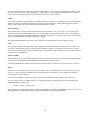
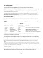
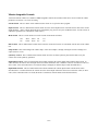
Pitch Wheel and Key-Pressure Bend
Note bending is when the played note rises or falls to another note by a smooth transition, as in Figure 6-1. It may or may not
return to the original note.
Figure 6-1. Note Bending.
The K150X allows you to control this effect in two ways - through the pitch wheel or through key pressure. Here, in the
program editor, you select the ranges in semitones for both of the bending options. The .P-BEND switch in the Layer Editor
allows you to select whether either or both of these options is active for a particular layer. All layers in the program set to the
same option will have the same amount of bend. With the .P-BEND switch, you can select among four pitch bending
options: off, wheel, press, or both. (See Layer Editing for more information.)
Pitch Wheel Bending
Assuming your MIDI controller has an assignable pitch wheel, it can bend a played note up or down, depending on which
way the wheel is rotated (no bending occurs when the wheel is in the center of its rotation). In order to hear the effect of your
changes, the .P-BEND parameter in one or more of the layers being played has to have the value wheel or both, and there has
to be proper MIDI assignment of the pitch wheel signal and/or the key velocity signal from the MIDI controller to the
K150X.
When the display reads .P-BEND you can adjust how many semitones away from the played note wheel rotation can bend
the sound. Use INCR and DECR to change the value by 1 semitone increments, or enter a value using the numeric buttonpad and press ENTR.
The value given is the amount in each direction. For instance, if 3ST is the value, the pitch wheel will bend the played note 3
semitones up and 3 semitones down. The maximum range is +/-6O semitones. New programs have their P-BEND set at a
default value of 2ST.
The sign of the value shows the relationship between the direction the pitch wheel is rotated and the direction of the pitch.
The convention is usually.
Wheel Direction
clockwise or up
Note Direction
up
6-3
Sign of Semitone Value
+
counterclockwise or down
down
-
If your pitch wheel is different, or you want to reverse the relationship, change the sign of the value.
Key-Pressure Bending
Assuming that your MIDI keyboard sends after-pressure information, notes can be specified to bend when played, the range
of the bend depending on the force with which you press the keys. The direction of the bending is specified by the sign of the
range. A positive value means the sound bends up from the played note. A negative value means the sound bends down.
In order to hear the effects of your changes, the .P-BEND parameter in one or more of the layers being played must be set to
Press or Both. There must also be proper MIDI assignment of the key velocity signal from your keyboard to the K150X.
When the display reads .K-BEND, you can set the distance (in semitones) after the played note at which pressing the key will
bend the note. Use the numeric button-pad to enter a value directly and press ENTR, or use INCR and DECR to change the
value by 1 semitone increments.
Change the direction of the bending by changing the sign of the value. The semitone value will be positive for a rising bend
and negative for a failing one.
New programs have their KP-BEND set at +1 ST by default.
Soft Pedal
The soft pedal acts as an attenuator to control the loudness and timbre of notes. This parameter is an unsigned value (in
decibels) which sets the range of the soft pedal. Note that if the soft pedal is assigned to a MIDI switch controller, it will take
on the values 0 (when OFF) and the maximum pedal range (when ON).
When the display reads .SFT-PDL, you can adjust the timbre range over which the sound will be diminished when the pedal
is pressed ±30dB. Use the numeric button-pad to enter a value directly and press ENTR or use INCR and DECR to change
the value by 1 decibel increments.
Left and Right Split Points
When a program is first defined, the center region is defined as being the full width of the keyboard. Left and right regions
are created by defining left and right split points for the center region, which essentially shorten the center region on either or
both sides. That is, the left and right split points delineate the lower and upper bounds of the center region.
Keyboard events which occur below the left split point are routed to the left region; events which are above the right split
point are routed to the right region. Each region can be given its own distinct layers, allowing the keyboard to be divided
into up to three different voices of arbitrary keyboard width.
Setting the Split Points
Select each split point individually when the appropriate display is visible. For the left split point, the display is
number .L-SPLIT current note
and for the right split point, the display is
number .R-SPLIT current note
number is the program number being edited, and current note is the keyboard position of the appropriate split. current note
will be flashing. In a program without a current left-hand split, the left-hand split is defined to be C in the 0 octave (the
bottom most keyboard key). C0 would be flashing. In a program without a current right-hand split, the right-hand split is
defined to be C in the 9th octave (the top most keyboard key). C9 would be flashing.
6-4
When the display shows .L-SPLIT or .R-SPLIT, you can use INCR and DECR to step through the keyboard keys.
Alternately, you can select the MIDI number of the key at which you want the split to occur. The key selected becomes the
last key in the center region. The MIDI number for each key is shown in Table 6-2, and Figure 6-2 relates the MIDI numbers
to keys on the keyboard.
Table 6-2
MIDI Key Number Chart
Note
C
C#
D
D#
E
F
F#
G
G#
A
A#
B
Key
C0
Octave
0
12
13
14
15
16
17
18
19
20
21
22
23
C1
1
24
25
26
27
28
29
30
31
32
33
34
35
2
36
37
38
39
40
41
42
43
44
45
46
47
3
48
49
50
51
52
53
54
55
56
57
58
59
4
60
61
62
63
64
65
66
67
68
69
70
71
5
72
73
74
75
76
77
78
79
80
81
82
83
6
84
85
86
87
88
89
90
91
92
93
94
95
7
96
97
98
99
100
101
102
103
104
105
106
107
8
108
109
110
III
112
113
114
115
116
117
118
119
C2
C3
C4
C5
C6
C7
C8
C9
12
24
36
MIDI Number
48
60
72
84
96
108
120
Figure 6-2. MIDI Numbers of C Keys.
The number is automatically translated from the MIDI number to the associated musical note (the new note) in the display. If
you selected the wrong MIDI number, you can repeat this step.
Left and Right Region Balances
The volume of the left and right regions can be adjusted relative to the center region and to each other.
When the display reads .L-BAL, you can adjust the volume of the left region. When the display reads .R-BAL, you can
adjust the volume of the right region. Either region can be adjusted : ±15dB.
Enter a value in dB directly using the numeric button-pad and press ENTR, or use INCR and DECR to change the value by 1
dB increments. If a value greater than 15 is entered, the value will be set to 15 (+ or -) when ENTR is pressed.
Note that region balancing is relative. When you raise the volume of a specific region, you are actually reducing the volume
of the other regions with respect to it. This is done to insure that the K150X’s output gain is always as high as possible.
6-5
The Region Editor
With the Region Editor, you select the region of the active program which you want to work in. When the Layer Editor is
selected, the editable layers will be those of the selected region.
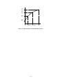
Technically, all programs have 3 regions. It is possible, however, to define the split points (in the Program Editor) such that
they are outside the range of the MIDI keyboard or controller you are using. For example, there are MIDI values for notes
from C in the 0 octave, to B in the 9th octave, but even a "full" range, 88-key piano keyboard goes only from A in the 0
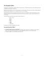
octave to C in the 8th octave, as shown in Figure 7- 1.
Key
C0
C1
C2
C3
C4
C5
C6
C7
C8
B9
12
24
36
MIDI Number
48
60
72
84
96
108
119
Figure 7-1. MIDI Numbers of C Keys.
Therefore, it is possible to select a region and edit its layers even though you can’t play it because no part of the actual
playing keyboard has been assigned to it.
Using the Region Editor
1.
Enter the Region Editor by pressing EDIT CANC. The regions edited will be those of the currently active program. To
edit the regions of another program, you must first select it to be the currently active program, and then press EDIT
CANC. The display will show:
Pn .CNTR LYRS r
where n is number of the current active program, and r is the number of layers currently defined for the region.
2.
Select a region to work on by using INCR, DECR, NEXT, or PREV, or select it using buttons 1, 2, or 3, corresponding
to "left", "center", and "right", and press ENTR.
Display Reads
.LEFT
.CNTR
.RGHT
Region
left region
center region
right region
Region Number
1
2
3
Additional information is given on the right side of the display on the number of layers in that region. The right side of the
display can read "0 LYRS", meaning that there are currently no layers defined, or it can read "LYRS n", where n is the
number of layers currently defined for that region. See the Layer Editor chapter for information on creating sound layers.
F1, F2, and F3 in the Region Editor
F1 deletes the selected region. You will be prompted before the region is deleted.
F2 copies the region in a storage buffer. You can then use F3 to insert that region somewhere else.
F3 replaces the selected region with the region stored in the storage buffer with F2 .
7-1
The Layer Editor
Most of the sound-shaping editing takes place at the layer level. Up to seven sound layers may be defined for each region of
a program.
Using the Layer Editor
Selecting and Editing Layers
Select Layer Editing by pressing EDIT UNDO. The layers selected to be edited are those of the center region unless you
specified another region previously using the Region Editor.
When you enter the layer editor, the display will show the program number, region (LEFT, CNTR, or RGHT), layer number
(flashing) and total number of layers in the region. For instance, the display for the center region of Program #1 would look
like:
P1
.CNTR LYR 1/1
If there are currently two or more layers defined, select a layer to work on by using INCR, DECR, NEXT, or PREV, or select
it by number using the numeric button-pad and press ENTR. If there is only one layer defined, that layer is the default layer
to edit, unless INCR is pressed, creating a new layer (see Creating and Deleting Layers).
Press ENTR to start choosing among the parameters for the selected layer. The display will show on the left side:
•
•
the region
− L for LEFT
− C for CENTER
− R for RIGHT
the Layer number
The parameters shown in Table 8-1 can be edited. One will appear in the display; the others can be selected using NEXT and
PREV.
Table 8-1
Layer Editor Parameters
Display Reads
Parameter
.VN
Voice
.TUNE
.TRANSPOSE
.T-MODE
Tuning
Transposition
Timbre-Mode
.T-SHIFT $
.T-SELECT &
.T-LEVEL
.B-MODE
Timbre-Shift
Timbre-Select
Timbre Level
Balance Mode
.BALANCE
Balance Level
Available Values
(use INCR and DECR)
a voice
±125C
±60ST
Fixed
Slider
A-Veloc
Select
±60ST
C0-C9
±30dB
Fixed
Slider
A-Veloc
±15dB
What it Does
Assigns the number and name of the voice to the
sound layer
Adjusts the tuning of the layer
Transposes the layer
Selects the way timbre is chosen
Controls the amount and direction of timbre shifting
Selects one note for all timbre shift
Selects Timbre Proportions
Controls the mode of layer balancing
Controls the relative volume of the layer
8-1
.P-MODE
Pitch Bend Mode
.C-MODE
Chorus Mode
.V-MODE
Vibrato Mode
.EQUALIZER
EQ Switch
Controls the mode of pitch bending
Off
P-Wheel
K-Press
Both
Off
M-Wheel
K-Press
Fixed
Off
M-Wheel
K-Press
Fixed
Off
On
Turns chorusing on and off
Controls the action of the vibrato unit
Turns equalization on and off
* If the value is numeric, you can enter the value with the right button-pad and press ENTR.
$ Does not appear when Select value is selected for T-SHIFT.
& Appears only when Select value is selected for T-SHIFT.
See the sections on each parameter later in this chapter.
F1, F2, and F3 in the Layer Editor
The operation of F1, F2, and F3 changes depending on whether you have pressed ENTR to begin editing the layer parameters
for a specific layer (step 3 above). Once you confirm the selection and begin editing the parameters (step 3 above), these
buttons have different meanings. F1 and F2 allow you to change the layer selection without re-entering the editor. F3 mutes
the other layers in the region, allowing you to hear only the layer you are editing.
Creating and Deleting Layers
Creating Layers
1.
To create a new layer, select the uppermost layer currently defined using any of the methods above and press INCR. The
display will read
New Layer?
Press ENTR, to define a new layer, or - to cancel the request. The new layer will be blank.
2.
To create a new layer from an existing one, select an existing layer and press F2 to copy it, then press F3 to insert the
copied layer into the region. Note that F3 always inserts layers.
Deleting Layers
To delete an existing layer, press F1. You will be asked for confirmation:
Delete Layer?
Press ENTR to delete a layer, or - to cancel the request.
Voice
The voice is the built-in sound selected as a basis for all editing changes in this layer. When a new layer is first defined, the
default voice is acoustic piano.
When the display reads .VN, you can select the voice. Enter the number of the desired voice using the numeric button-pad
and press ENTR, or use INCR and DECR to step through the available voices.
8-2
The built-in voices are either accurate electronic reproductions of conventional instruments, or unconventional sounds which
highlight the unique sound generation capabilities of the K150X. The built-in voices include these Resident Voices listed in
Table 8-2.
Table 8-2
Resident Voices
Voice Number
1
2
3
4
5
6
7
8
9
10
11
12
13
14
Display Reads
PIANO
ROCK PNO
SOFT PNO
ELECPNO
BR E-PNO
HARPISCHD
SOFTHPCD
A BASS
E BASS
SOFT EBS
VIBES
MARIMBA
JAZZ ORG
ROCK-ORG
Sound Name
Acoustic Piano
Rock Piano
Soft Piano
Electric Piano
Bright Electric Piano
Harpsichord
Soft Harpsichord
Acoustic Bass
Electric Bass
Muted Electric Bass
Vibes
Marimba
Jazz Organ
Rock Organ
There are also additional Sound Block Voices.
Tuning
Each layer can be individually tuned by cents. This tuning is in addition to the master tuning for the entire device as
specified with the Tuning Editor. For example, if the Master Tuning for the K150X is set at +3C, and a layer is given a
tuning of +2C, the layer will have a +5C tuning relative to the natural pitch.
When the display reads .TUNE you can adjust the tuning of the layer from 0 to +/-125 Cents. Enter a value using the
numeric button-pad and press ENTR, or use INCR and DECR to change the value by 10 cent increments.
If a value greater than 125 is entered using the numeric button-pad, the value will be set to 125 when ENTR is pressed.
Transposition
Each layer can be individually transposed by semitones. This transposition is in addition to the master transposition for the
entire device as specified with the Tuning Editor. For example, if the master transposition for the K150X is set at +3ST, and
a layer is given a transposition of +2ST, the layer will have a +5ST transposition relative to the natural tone.
When the display reads .TRANSPOSE you can adjust the transposition of the layer from 0 to +/-60 semitones. Enter a value
using the numeric button-pad and press ENTR, or use INCR and DECR to change the value by 1 semitone increments.
If a value greater than 60 is entered using the numeric button-pad, the value will be set to 60 when ENTR is pressed.
Timbre Mode
About Timbre
Timbre describes the harmonic content of the note in addition to the nominal pitch. For most conventional instruments, the
harmonic content of the timbre changes over time while the nominal pitch remains reasonably constant. The harmonic
content of the timbre also changes with the loudness of the note.
8-3
All built-in sounds have a pre-selected timbre formula as a component of every note. Timbre-Shift allows you to override the
default timbre and choose another timbre for a keyboard key when it is pressed. With Timbre-Shift, you can override the
internal formula and use the timbres from other notes in the scale in conjunction with the nominal pitch. Timbre shifts are
similar to transpositions, but they only change the harmonic content of the note and have no effect on the pitch of the note.
The effect of timbre-shifting varies depending on the built-in voice. In the case of the acoustic piano voice, positive timbre
shifts, which will cause the timbres from lower notes to played at higher pitches, result in a bright, funky sound. Negative
adjustments, which use the timbres from higher notes to be played at lower pitches, result in a darker sound.
The Timbre Mode Options
When the display reads .T-MODE, you can choose among four options for selecting your timbres. The default option is
manual. Use INCR and DECR to step through the choices.
Manual
When used with the default value for .T-SHIFT (0 semitones), this option creates the default timbre mode.
Picking a shift in semitones with .T-SHIFT changes the sound (See Timbre-Shift Value).
Slider
If your MIDI controller has a MIDI-assignable slider or wheel, you can set it up so that you can interactively shift
the timbre between the nominal timbre and .T-SHIFT selected timbre by moving the controller. In order for this
option to work, you have to make the proper MIDI assignment of the controller (see Assignment Editor).
Attack Velocity (A-VELOC) If your MIDI controller can transmit key velocity information, the amount of .T-SHIFT timbre
applied to the nominal pitch can be proportional to the velocity with which the key is played by selecting the .AVELOC Timbre-Shift option.
Select
Used in conjunction with the .T-SELECT, this option takes the timbre from one note and applies it to all notes.
You choose the note with the .T-SELECT parameter (see Timbre-Select). The default note is middle C (C4 = C in
the 4th octave).
Timbre-Shift Value
Used in conjunction with the first three Timbre-Shift Modes described above (manual, slider, or a-veloc), this parameter
appears as a Layer Editor Parameter only if one of those first three modes is selected, and not if the select option is chosen. It
allows you to specify the amount to shift the timbre, relative to the played note, in semitones. For instance, if the TimbreShift Value is given as +1ST, and C is played, then the timbre for C# will be played with the nominal B pitch. Likewise, if
the Timbre-Shift Value is given as -1 ST, and C is played, then the timbre for C# will be played.
When the display reads .T-SHIFT you can adjust the timbre shift of the layer from 0 to ±60 semitones. 0 is the default, and
applies all timbre-shifts to their nominal pitches. Enter a value using the numeric button-pad and press ENTR, or use INCR
and DECR to change the value by 1 semitone increments. To change the sign of the value, use the - key.
In general, positive timbre-shifts result in a brighter sound, while negative timbre-shifts result in a duller sound.
Timbre-Select
Used in conjunction only with the Select option of the Timbre-Shift Mode parameter, this parameter allows you to specify the
note whose timbre will be applied to all the notes. The default note is middle C (C4 = C in the 4th octave).
There are 2 ways to select the note. Press INCR and DECR to step through the musical scale. Alternatively, you can select
the MIDI number of the key whose timbre shift you want. Input the value using the numeric button-pad and press ENTR.
The MIDI number for each key is shown in Table 8-3, and Figure 8-1 relates the MIDI numbers to keys on the keyboard.
Table 8-3. MIDI Key Number Chart.
Note
C
Octave
0
1
12
24
2
36
3
48
4
60
5
72
6
84
8-4
7
96
8
108
C#
D
D#
E
F
F#
G
G#
A
A#
B
Key
C0
13
14
15
16
17
18
19
20
21
22
23
C1
25
26
27
28
29
30
31
32
33
34
35
37
38
39
40
41
42
43
44
45
46
47
49
50
51
52
53
54
55
56
57
58
59
61
62
63
64
65
66
67
68
69
70
71
73
74
75
76
77
78
79
80
81
82
83
85
86
87
88
89
90
91
92
93
94
95
97
98
99
100
101
102
103
104
105
106
107
109
110
III
112
113
114
115
116
117
118
119
C2
C3
C4
C5
C6
C7
C8
C9
12
24
36
MIDI Number
48
60
72
84
96
108
120
Figure 8-1. MIDI Numbers of C Keys.
The number is automatically translated from the MIDI number to the associated musical note in the display. If you selected
the wrong MIDI number, you can repeat this step.
Timbre-Level
The loudness proportions between timbres for the note being played can be modified. This parameter changes the
relationship of key velocity to timbre without affecting the relationship of key velocity to loudness. Its effect can be thought
of as being similar to the soft pedal, but with reversed values: a +30dB value given to .T-LEVEL will have the effect of
emphasizing the loud timbres, while the same value given to .SFT-PDL would emphasize the soft timbres.
When the display reads .T-LEVEL, you can adjust this value ±30dB. The default is 0dB, which is full range. Enter a value
in decibels using the numeric button-pad and press ENTR, or use INCR and DECR to change the value in 1 decibel
increments. If a value greater than 30dB is entered using the numeric button-pad, the value will be set to 30dB when ENTR
is pressed.
dB
+30
0
-30
T-LEVEL
loud timbre only
full range
soft timbre only
SFT-PDL
soft timbre only
loud timbre only
Balance Mode
The volume of each individual layer can be set with the Balance Level parameter described next, and can be controlled by
one of three methods selectable with the Balance Mode Parameter. When the display reads .B-MODE, you can choose
among three options for controlling the balance. The default mode is manual. Use INCR and DECR to step through the
choices:
Manual
This is the default mode for layer balance. The value given in the Balance Level parameter is directly applied to
the layer.
Slider
If your MIDI controller has a MIDI-assignable slider or wheel, you can set it up so that you can interactively
control the balance level between 0dB and the value set with the Balance Level parameter.
Attack Velocity (A-VELOC) If your MIDI controller can transmit key velocity information, the balance can be controlled
by key velocity. When the display reads .A-VELOC, the balance level is scaled between 0dB and the value set
with the Balance Level parameter, and proportional to the velocity with which the key is pressed.
8-5
Balance Level
When the display reads .BALANCE, you can control the volume of this layer relative to the other layers. The volume of this
layer can be adjusted to be 0 to 12dB softer than an unadjusted layer. The default value is 0dB.
Enter a value in decibels using the numeric button-pad and press ENTR, or use INCR and DECR to change the value in 1
decibel increments. If a value greater than 12dB is entered using the numeric button-pad, the value will be set to 12dB when
ENTR is pressed.
Note that layer balancing is relative. When you raise the volume of a specific layer, you are actually reducing the volume of
the other layers with respect to it. This is done to insure that the K150X’s output gain is always as high as possible.
Pitch Bend Mode
Pitch bending is when the played note rises or falls to another note by a smooth transition, as in Figure 8-2.
Figure 8-2. Pitch Bending.
Assuming that your MIDI controller has a MIDI-assignable continuous controller such as a wheel, knob, or slider, and/or can
transmit key after-touch information, this parameter allows you to choose which combination (if any) of control information
will control the pitch bending for this layer.
The range of the pitch bending is a program-wide parameter and is controlled in the Program Editor. The default values are
+2 semitones for wheel bending, and +1 semitones for key-pressure bending (see Program Editing).
When the display reads .P-MODE, you can choose among four pitch bend control options. Use INCR and DECR to step
through the choices.
Off
Disables the pitch bending capabilities of this layer.
P-Wheel
Only the pitch wheel is selected for pitch bending. Its range is determined by the .P-BEND parameter in the
Program Editor (see Program Editing).
K-Press
Only key pressure is selected for pitch bending, with the amount of bend being proportional to the after-touch
pressure with which you hold the key down. Its range and direction are determined by the .K-BEND parameter in
the Program Editor (see Program Editing).
Both
Both pitch wheel and key pressure bending are enabled.
Chorus Mode
This parameter selects whether chorusing is active in this layer. and specifies how. The switch selected here works in
conjunction with the chorus settings edited with the Chorus Editor (one set of chorus parameters can be defined for each
program).
When the display reads .C-MODE, you can choose among the Chorus switch options. Use INCR and DECR to step through
the available switch options. The default is off.
Off
Chorusing is disabled for this region.
Fixed
Chorusing is enabled in a normal mode; i.e., the chorus detuning will not respond to MIDI key pressure or
modulation wheel signals.
8-6
K-Press
Assuming your MIDI controller can transmit key after-touch information, the amount of detuning, as specified
with the .DTUNE parameter of the Chorus Editor can be proportional to the after-touch with which the key is held
down with this option (see Chorus Editing for more information).
M-Wheel Allows the amount of detuning, as specified with the .DTUNE parameter of the Chorus Editor, to be controlled
with your MIDI controller’s modulation wheel (see Chorus Editing for more information).
Vibrato Mode
This parameter selects whether vibrato is active in this layer, and specifies how. The switch selected here works in
conjunction with the vibrato settings edited with the Vibrato Editor (one set of vibrato parameters can be defined for each
program). When the display reads .V-MODE, you can choose among the Vibrato switch options. Use INCR and DECR to
step through the available switch options. The default is off.
Off - Vibrato is disabled for this region.
Fixed
Vibrato is enabled in a normal mode; i.e., the vibrato intensity will not respond to MIDI key pressure or
modulation wheel signals.
K-Press
Assuming your MIDI controller can transmit key after-touch information, the amount of vibrato depth, as
specified with the .DEPTH parameter of the Vibrato Editor can be proportional to the after-touch with which the
key is held down with this option (see Vibrato Editing for more information).
M-Wheel Allows the amount of vibrato depth, as specified with the .DEPTH parameter of the Vibrato Editor, to be
controlled with your MIDI controller’s modulation wheel (see Vibrato Editing for more information).
Equalizer Number
This parameter selects whether equalization is active in this layer. When the display reads .EQUALIZER, you can use INCR
and DECR to switch between on and off. The default is on.
One set of equalization parameters can be defined for each program. Use the Equalizer Editor to edit the equalization
parameters for the active program (see Equalizer Editing).
8-7
The Chorus Editor
The programmable chorusing feature in the K150X can be used to create a variety of effects such as phasing, flanging,
doubling, chorusing, and echo. The chorusing feature operates by generating extra notes which can be successively detuned,
delayed and/or decayed.
You can define one set of Chorus parameters for each Program. Whether or not these Chorus parameters are active for any
individual layer in that program is controlled by the Chorus Enable switch for each layer which can be set to Off, Fixed, MWheel, or K-Press (the default is Off). To fully understand the capabilities of Chorus mode, see the description of the various
chorus enabling options in Layer Editing.
The Chorus parameters being modified are those for the currently active program. In order to hear the effects of your Chorus
editing, turn on one of the active modes (Fixed, K-Press, or M-Wheel) of the Chorus Enable switch for the layer or layers you
want to add Chorus to (see Layer Editing).
Using the Chorus Editor
Select CHORUS editing by pressing EDIT INCR (The word CHORUS is printed above the key on the button-pad).
The parameters shown in Table 9-1 (on the following page) can be edited. One will appear in the display; the others can be
selected by using NEXT and PREV.
Table 9-1
Chorus Editor Parameters
Display Reads
Parameter
.X-NOTES
.DTUNE
.DELAY
.DECAY
Extra Notes
Detune
Delay
Decay
Adjustable Range *
(use INCR and DECR)
0-7
±0-6,000C
0-4000ms
0-12dB
What it Does
Selects the number of extra notes to be played.
Varies the pitch of the successive notes.
Delays each successive note by the given time interval.
Reduces the volume of each successive note.
* You can also enter the value directly with the right button-pad and press ENTR.
See the sections on each parameter later in this chapter.
The Chorusing parameters work in conjunction with each other. For instance, until audibly perceptible values are set for
Detune and Delay, selecting multiple notes will not sound dramatically different; it will just "fatten" up the sound of the
original note. Likewise, selecting 3 Notes and a Delay of 200 ms, with no detuning, will only repeat the original sound 3
times, 200 ms apart.
Remember that you can interactively listen to your modifications to the Chorus editor. To do this, at least one layer in the
region of the keyboard that you’re playing must have its Chorus Enable switch on (see Layer Editing). When you select
values using the numeric button pad and press ENTR or change values using INCR and DECR, the changes in sound can be
heard by playing the keyboard. Also note that you can press UNDO to toggle between the current value and the previous
value, or CLR to reset a value to 0.
Notes
When the display shows .X-NOTES, you can select the number of extra notes to sound. Enter the value directly with the
numeric button-pad and press ENTR or use INCR and DECR to add or subtract one note at a time.
Up to 7 notes can be selected. If you enter a value greater than 7 using the numeric button-pad, the number of notes will be
set to 7 when ENTR is pressed.
9-1
Detune
When the display reads .DTUNE, you can specify the amount to detune and mode of detuning for successive notes. Detuning
amount specifies how much the chorus generated pitches will vary from the played note. The mode determines whether these
additional notes are above or below the pitch of the played note, or alternate between being above and below.
You can select the detuning amount to be between 0 and 2000 cents. Enter a value in cents using the numeric button-pad and
press ENTR, or use INCR and DECR to change the value by 10 cent increments.
The mode of the de-tuning can be adjusted using the sign button, - . Pressing - steps through the four values +, -, ±, -/+ :
+
±
-/+
above
below
alternates between above & below; starts above
alternates between below & above; starts below
For example, if 4 extra notes and 200 cents (1 whole tone) of de-tuning are specified, the effect of playing a note for each
sign value is shown in Figure 9-1.
+
Above
Below
+/Above/Below
-/+
Below/Above
"
#
$
%
&
!
Figure 9-1. Detuning.
Delay
When the display reads .DELAY, you can adjust the amount of time between each note from 0 to 4000 ms (4 seconds) in
millisecond increments.
Enter a value in milliseconds directly using the numeric button-pad and press ENTR, or use INCR and DECR to change the
value by 10 ms increments. If you enter a value greater than 4000 ms, the delay value will be set at 4000 ms when ENTR is
pressed.
You can also use the INCR and DECR keys to change the value in 10 ms increments.
Decay
When the display reads .DECAY, you can lower the volume of successive notes in relation to the previous one from 0 to
12dB in 1 dB increments.
Enter a value directly using the numeric button-pad and press ENTR, or use INCR and DECR to change the value by 1 dB
increments. If you enter a value larger than 12 with the numeric button-pad, the decay value will be set at 12 when ENTR is
pressed.
Chorus Editor Assignable Controls
Associated with the chorusing are a number of MIDI-assignable controls and switches which can be used to control the
chorusing parameters in real time. See Controls Editing.
On/Off Switch. This switch turns the chorusing on and off. When a chorus unit is turned off, any extra notes are turned off
as well.
9-2
Detune Control (unidirectional). This control varies the successive detune between 0 and the value set in the chorusing
parameters. Chorus detune is a live effect (i.e., it is effective after the note has started.).
Detune Mode Switch. This switch changes the sign of detune mode (i.e., + becomes -; ± becomes -/+).
Detune/Mode Control (bidirectional). This is a bidirectional control that combines the detune control with the mode switch.
When the control is above center (or below if the direction is reversed), the detune is varied and the normal mode is used. In
the other direction, the detune mode is reversed.
Delay Control (unidirectional). This control varies the successive delay between 0 and the value set in the chorusing
parameters. It is only effective when a note is started.
Decay Control (unidirectional). This control varies the successive decay between 0 and the value set in the chorusing
parameters. It is only effective when a note is started.
Chorus Editor Hints
Chorusing can generate multiple notes for a single key event. The K150X can produce 16 notes simultaneously. If you play
a chord while chorusing is enabled, the sound quality may be thinner than expected because the total number of notes you are
trying to generate exceeds the 16-note maximum.
One "trick" you can try is to set some small delay (5ms) between chorused notes using the Delay parameter. This will greatly
expand the K150X’s note generation capability.
Try the initial settings in Table 9-2 in order to create popular effects.
Table 9-2
Popular Chorusing Effects
Effect
X-NOTES
Chorusing
Doubling
Phasing/Flanging
Echo
≥2
1
1
2-3
DTUNE
cents
5
5 - 10
5
-
9-3
DELAY
ms
25
33
3-5
>100
DECAY
moderate
The Vibrato Editor
The programmable vibrato feature in the K150X allows you to create a variety of frequency-shift effects.
You can define one set of Vibrato parameters for each Program. Whether or not these Vibrato parameters are active for any
individual layer in that program is controlled by the Vibrato Enable switch for each layer which can be set to Off, Fixed, MWheel, or K-Press (the default is Off). To fully understand the capabilities of Vibrato mode, see the description of the
various vibrato enabling options in Layer Editing.
The Vibrato parameters being modified are those for the currently active program. In order to hear the effects of your
Vibrato editing, turn on one of the active modes (Fixed, K-Press, or M-Wheel) of the Vibrato Enable switch for the layer or
layers you want to add Vibrato to (see Layer Editing).
Using the Vibrato Editor
Select VIBRATO editing by pressing EDIT DECR (The abbreviation VIBR is printed above the DECR key on the buttonpad).
The parameters shown in Table 10-1 can be edited. One will appear in the display; the others can be selected by using NEXT
and PREV.
Table 10-1
Vibrato Editor Parameters
Display Reads
Parameter
.TRIANGLE
.SQUARE
.DEPTH
.RATE
.SYMMETRY
.DELAY
triangle wave
square wave
Depth of Oscillation
Oscillation Rate
Symmetry of Waveform
Vibrato Delay
Available Values *
(use INCR and DECR)
Triangle
Square
0-3600 C
0-49.9 Hz
±10
0-1000ms
What it Does
Selects the base waveform used for modification.
Adjusts the range in which the sound will vary.
Adjusts the frequency of oscillation.
Adjusts the symmetry of the waveform.
Specifies a delay before vibrato reaches full intensity.
* If the value is numeric, you can also enter the value directly with the right button-pad and press ENTR.
See the sections on each parameter later in this chapter.
The Vibrato parameters work in conjunction with each other. For instance, until an audible value is set for .RATE, changes
to the other parameters will not be audible. Likewise, if .DEPTH is set to 0C, no audible oscillation occurs because the note
doesn’t change.
Remember that you can interactively listen to your modifications to the Vibrato editor. To do this, at least one layer in the
region of the keyboard that you’re playing must have its Vibrato Enable switch enabled (on, delayed, or press (see Layer
Editing).
When you select values using the numeric button pad and press ENTR, or change values using INCR and DECR, the changes
in sound can be heard by playing the keyboard. Also note that you can press UNDO to toggle between the current value and
the previous value, or CLR to reset a value to its default value.
Triangle or Square
When the display shows .TRIANGLE or .SQUARE, you can select the waveform used by Vibrato. With .TRIANGLE, the
sound will "ease" from the played note to the limit of oscillation specified with the .DEPTH parameter, and back again. With
.SQUARE, the sound will "jump" between the limits of oscillation. The two waveforms are shown in Figure 10-1.
10-1
Square
Triangle
Vibrato
Trill
Figure 10-1. Triangle vs. Square waves
The musical effect is approximately as shown in Figure 10-2.
Triangle Wave Vibrato
'
(
)
Square Wave Vibrato
+
*
,
-
.
Figure 10-2. Musical Effect.
Use INCR and DECR to alternate between .SQUARE and .TRIANGLE.
Depth
When the display shows DEPTH, you can select the depth and mode of the oscillation. Depth is the amount that the pitch
will vary, in cents. Mode is how this variation will occur in relation to the nominal pitch. above it (+), below it (-), or
varying both above and below (±, -/+). When you choose both, mode selects which wave the oscillation starts: ± means the
oscillation starts positive and goes negative, -/+ means the oscillation starts negative and goes positive. Figure 10-3
illustrates modes of selection for a triangle wave.
+
−
+
−
−
+
Figure 10-3. Triangle Wave Modes
The depth can be selected to be between 0 and 3600C. Enter a value in cents using the numeric button-pad and press ENTR,
or use INCR and DECR to change the value by 10 C increments. Note that if the depth is selected to be 0, no vibrato effect
will be audible.
Select the desired mode by pressing - to step through each of the four choices: +, -, ±, -/+.
Rate
When the display shows .RATE, the frequency at which the vibrato occurs can be selected. A low frequency results in a
"slow" vibrato effect, while a high frequency results in a "fast" vibrato effect.
The frequency can be adjusted from 0 to 49.9Hz. Enter a value directly using the numeric button-pad and press ENTR, or
use INCR and DECR to change the value by 0.1 Hz increments. Note that if 0Hz is selected, no vibrato effect will be
audible.
10-2
Symmetry
Up to this point, vibrato waveforms have been symmetric. Symmetry allows you to specify a value which modifies the
vibrato waveforms as shown in Figure 10-4.
Triangle
-10
-5
0
5
10
Square
Figure 10-4. Modifying Waveform Symmetry.
Enter a value directly using the numeric button-pad and press ENTR, or use INCR and DECR to change the value 1 step at a
time.
Note that it is possible to create ramps (sawteeth) using the -10 or +10 symmetry values in conjunction with the triangle
wave. Figure 10-5 shows waveforms for representative mode/symmetry value combinations.
Triangle
-10
-5
0
5
10
Square
Figure 10-5. Mode/Symmetry Value Combinations.
Delay
The delay parameter establishes an "onset" delay for vibrato where the vibrato depth increases gradually after the note starts
and reaches full depth after the delay time specified has elapsed.
When the display shows .DELAY, you can specify a delay from 0 to 1000 ms (1 second). Enter a value directly using the
numeric button-pad and press ENTR or use INCR and DECR to change the value 10 ms at a time.
10-3
Vibrato Assignable Controls
Associated with the vibrato are a number of MIDI-assignable controls and switches which can be used to control the vibrato
parameters in real time. See Controls Editing.
On/Off Switch. This is a master switch which turns the vibrato on or off for the entire program.
Depth Control. This is a unidirectional control which varies the vibrato depth between 0 and the current value of the vibrato
depth parameter. (Note: Vibrato depth can also be controlled by key pressure or by the modulation wheel. See the section on
sound layer parameters for a discussion of this feature.)
Mode Switch. This is a switch which reverses the current vibrato mode as follows:
Off
On
above
below
below
above
a/b
b/a
b/a
a/b
Rate Control. This is unidirectional control which varies the vibrato rate between 0.1 Hz and the current value of the vibrato
rate.
Shape Switch. This switch changes the vibrato shape. If the current shape is triangle, turning the switch on changes it to
square (and vice versa).
Symmetry Control. This is a bidirectional control which varies the waveform symmetry between the limits set by the
current value of the symmetry parameter.
Depth/Shape Control. This is a bidirectional control which combines the vibrato depth control and the shape switch. In
either direction, the control varies the depth between 0 and the maximum value. When the control is moved below center (or
above center, if the control direction is reversed) the shape is changed (as with the shape switch described above).
Depth/Mode Control. This is a bidirectional control which combines the vibrato depth control with the mode switch
described above. In either direction, the control varies the vibrato depth. When the control is moved below center (or above
center, if the control direction is reversed) the mode is switched (as with the mode switch described above).
10-4
The Equalizer Editor
Each program in the K150X has a graphic equalizer associated with it. Each equalizer provides 8 octave bands with a range
of 12dB boost and 30dB cut for each band.
Whether or not this equalizer is active in any particular layer of the program is controlled by the Equalizer Enable parameter
in the layer editor, which can be set on or off for each layer (see Layer Editing).
The Equalization parameters being edited are those for the currently active program. In order to hear the effects of your
equalization editing, turn on the Equalization Enable switch for the layer or layers you want to apply equalization to (see
Layer Editing).
Each equalizer has eight bands centered about the follow frequencies:
62.5 Hz (shelf)
125 Hz
250 Hz
500 Hz
1 kHz
2 kHz
4 kHz
8 kHz (shelf)
Each band may be boosted by 12dB or cut by 30dB.
Using the Equalizer Editor
1.
2.
3.
Select Equalizer Editing by pressing EDIT CLR
One of the frequencies listed above will appear in the display with its current value. Change the value by using the
numeric button-pad and pressing ENTR, or use INCR and DECR to change the value by 1dB increments.
Use NEXT and PREV to step through the other frequencies.
11-1
The Control Editor
This editor allows you to assign MIDI control sources to K150X control destinations. Just as MIDI has two types of control
sources (continuous controllers and switches), the K150X has two types of control destinations: virtual controls and virtual
switches. Virtual controls recognize the full range of MIDI data values (0 thru 127) while virtual.switches only respond to 0
(OFF) and 127 (ON). There is, however, no restriction on assigning MIDI switches to virtual controls, or MIDI controllers to
virtual switches.
Virtual controls are either unidirectional (0 is minimum, 127 is maximum) or bidirectional (with 64 as the center point). The
direction of the value, as indicated by the arrow symbol in the K150X display, can be reversed by pressing the - key. For
example, a control which sends higher MIDI values when turned clockwise can be reversed, having its signal interpreted as
being lower MIDI values when turned clockwise. The pitch bender is an example of a bidirectional control.
When a continuous controller is assigned to a virtual switch, the switch will only react to the extremes of the controller range
(OFF and ON); any intermediate values are ignored. In the opposite case, the virtual switch will only see two values (0 and
127) which correspond to the minimum and maximum range of the controller.
Note that the pitch wheel and monophonic channel pressure are treated as extra continuous controllers; they can be assigned
to any control or switch destination. Polyphonic key pressure is distributed directly to individual notes and can be used to
scale a number of sound layer parameters. For controllers that do not generate polyphonic pressure, a virtual control is
provided which allows any control source to act like polyphonic key pressure.
The K150X also provides a connection for two external switch pedals. These pedals are treated as extra switch controllers
and can be assigned to any control or switch destination.
F1, F2, and F3 in the Control Editor
Pressing F1 returns you to the top of the list.
Pressing F2 jumps to the first of the Chorus control assignments.
Pressing F3 jumps to the first of the Vibrato control assignments.
Using the Control Editor
1.
Select Control Editing by pressing EDIT NEXT.
2.
One of the parameters shown in Table 12-1 will appear in the display. Use NEXT and PREV to step through the
parameters.
Table 12-1
Summary of Assignable Controls
Display Abbreviation
Control Name
Type of Control
MIDI Assignment
MODULATION
P-WHEEL
KEY PRESS
P-SHIFT
TRANSPOSE
TIMBRE SHIFT
VOLUME
BALANCE
EXPRESSION
Modulation
Pitch Wheel
Key Pressure
Pitch Shift
Transpose
Timbre Shift *
Volume
Balance
Expression
CC±
CC±
CC±
CC±
CC±
CC±
CC±
CC±
CC±
1
126
125
Unassigned
Unassigned
Unassigned
7
8
11
TIMBRE FREEZE
SOSTENUTO
SUSTAIN PED
Timbre-Freeze * Pedal
Sostenuto Pedal
Sustain Pedal
SW
SW
SW
69
66
64
12-1
SOFT PEDAL
Soft Pedal
CC
67
CHORUS SW
C-DTUNE CC
C-MODE SW
C-MODE CC
C-DELAY CC
C-DECAY CC
Chorus Switch
Chorus Detune
Chorus Mode
Chorus Mode/Detune
Chorus Delay
Chorus Decay
SW
CC
SW
CC
CC
CC
Unassigned
Unassigned
Unassigned
Unassigned
Unassigned
Unassigned
VIBRATO SW
V-DEPTH CC
V-SHAPE SW
V-SHAPE CC
V-RATE CC
V-MODE CC
V-MODE SW
V-SYM CC
V-DELAY CC
Vibrato Switch
Vibrato Depth
Vibrato Switch
Vibrato Depth/Shape
Vibrato Rate
Vibrato Mode
Vibrato Mode
Vibrato Symmetry
Vibrato Delay
SW
CC
SW
CC±
CC
CC
SW
CC
CC
Unassigned
Unassigned
Unassigned
Unassigned
Unassigned
Unassigned
Unassigned
Unassigned
Unassigned
DATA ENTRY
INCREMENT
DECREMENT
NEXT PROG
PREV PROG
NOTES OFF
Data Entry
Increment
Decrement
Next Program
Previous Program
Notes Off
CC
SW
SW
SW
SW
SW
6
96
97
Unassigned
Unassigned
127
Legend:
SW
CC
CC±
* Trademark of Kurzweil Music Systems, Inc.
switch
continuous controller
bidirectional continuous controller
How Assignment is Done
Table 12-2 contains the assignments for standard MIDI control numbers according to the latest MIDI specification.
Unassigned control numbers are available for assignment to any K150X control destination.
Table 12-2
MIDI Control Assignments
MIDI #
0
1
2-5
6
7
8
9-10
11
12-31
32-63
64
65
66
67
68
69
Default Assignment
(ignored)
Modulation Wheel
(unassigned)
Data Entry
Volume
Balance
(unassigned)
Expression
(unassigned)
(all LSBs ignored)
Sustain Pedal
(unassigned)
Sostenuto Pedal
Soft Pedal
(unassigned)
Timbre-Freeze* Pedal
12-2
70-95
96
97
98-121
(unassigned)
Data Increment
Data Decrement
(unassigned)
The following numbers are not valid MIDI control numbers. They are used internally to designate MIDI control sources
which are transmitted as separate MIDI messages:
Table 12-3
Invalid MIDI Control Numbers
MIDI #
125
126
127
Default Assignment
Channel Pressure Message
Pitch Wheel Message (MSB only)
All Notes Off Message
Only one control source can be assigned to a control destination. When editing, the INCR and DECR keys skip over
previously assigned control sources. If you enter a control source number directly with the numeric keypad, any previous
assignment is canceled.
Assignable Controls and Switches
The following sections describe the basic controls and switches. The chapters on the programmable chorusing and vibrato
units describe the controls and switches which are specific to those devices.
Sustain Pedal
The sustain pedal is a switch that behaves exactly like its piano counterpart. While it is down (ON) notes will continue to
sound even after their keys have been released.
Sostenuto Pedal
The sostenuto pedal is a switch that behaves exactly like its piano counterpart. While it is down (ON) any notes whose keys
were down when the pedal was depressed will be sustained, but subsequent notes are not effected.
Timbre-Freeze Pedal
The Timbre-Freeze pedal is a switch that behaves like a sostenuto pedal, but activates an effect called Timbre Freeze*.
While it is down (ON) any notes whose keys were down when the pedal was depressed are frozen. That is, their timbral
evolution is suspended. When the pedal is released, the notes will continue to evolve if their keys are still down or the
sustain pedal is down. Otherwise, they will release.
Soft Pedal
The soft pedal is actually a continuous control that acts as an attenuator to control the timbre of notes. If assigned to a switch
controller it is either fully up (OFF) or fully down (ON). If it is assigned to a continuous controller then it can take on any
value between 0 and its maximum attenuation value, which is a program level parameter.
Mute Pedal
When the mute pedal is depressed (ON) all active notes on the associated channel are released. Subsequent notes (started
while the pedal is still down) are not effected. The mute pedal is permanently assigned to the All-Notes-Off MIDI message.
Pitch Bender
The pitch bender is a bidirectional controller which bends the pitch of all notes on a particular channel. Its range is
adjustable in semitones and it set at the program level. Its effect can be selectively enabled at the layer level.
Pitch Shifter
The pitch shifter is a bidirectional controller which changes the pitch of notes in semitone steps (providing a shift range of
+63 to -64 semitones).
12-3
The pitch shifter can be used in conjunction with the programmable buttons on the MIDIBoard to create buttons that shift the
pitch up or down in semitones. For example, programming a button to send 64 when OFF and 76 (i.e., 64+12) when ON
creates an "octave up" switch.
Transpose Control
The transposer is a bidirectional control which transposes all notes on a particular channel. The value of the transpose
control is additively combined with the Master Transpose and Layer Transpose. Note that transposition is a static effect.
Varying the control will not effect notes that have already started.
Timbre Shift Control
The timbre shift control is used to scale the layer transpose value. Its effect can be selectively enabled at the layer level.
Note that timbre shift is only effective at the start of a note.
Balance Control
The balance control is a bidirectional controller used to scale the balance adjustment in the sound layer. Its effect can be
selectively enabled at the layer level. This control is only effective at the start of a note.
The balance control can be used to change the level between two sound layer give one layer a positive balance adjustment
and the other a negative value. Enable the balance control for both. When the control is at the midpoint, both layers will be
equally loud. Moving the control above or below center will increase the loudness of one layer and decrease the loudness of
the other.
Pressure Control
The pressure control allows any continuous controller to act like polyphonic key pressure. The default assignment for the
pressure control is monophonic channel pressure, which means that mono channel pressure acts like polyphonic key pressure.
Expression Control
The expression control is a bidirectional controller which converts the incoming MIDI value from -64 to +63. This value
gets added to the key velocity value after the velocity map.
You might use this control with a pedal, to simulate touch sensitivity for a non-touch sensitive keyboard.
Volume Control
This is a continuous controller which adjusts volume from 0 dB (MIDI value 128) to -48 dB (MIDI value 0).
12-4
The Miscellaneous Editor
The Miscellaneous Editor allows you to choose from an additional set of editors: the Program List Editor, the Intonation
Editor, and the Velocity Map Editor.
Using the MISC Editor
1.
Select the Miscellaneous Editor by pressing EDIT PREV. One of the following editor names will appear in the display.
Use NEXT and PREV to step through the choices shown in Figure 13- 1.
2.
Press ENTER to select a particular editor.
Table 13-1
The Miscellaneous Editors
Display Reads
PROGRAM LIST
INTONATION
VELOCITY MAP
Editor
Program List Editor
Intonation Editor
Velocity Map Editor
What it Does
Allows you to map program numbers to program list numbers
Adjusts the interval width between notes
Allows you to modify the K150X’s velocity maps
Once you select a particular editor by pressing ENTER, you must re-enter the Miscellaneous Editor by pressing EDIT PREV
in order to choose another editor.
The Program List Editor
Used in conjunction with the PROGRAM LIST parameter in the MIDI editor, the Program List Editor allows you to set up
maps between a number in the program list and the actual program number to be played when that program list number is
played.
This feature is useful when changing program numbers remotely from your MIDI controller. Depending on how many
programs your controller selects from at one time, you can set up the K150X to have up to 128 programs accessible directly
from your controller.
Using the Program List Editor
When the display reads PROGRAM LIST, press ENTR. The display will read.
STEP n PROG n
where STEP is the program list number currently being assigned, and PROG is the program number being assigned to that
program list number.
To change the STEP number, use NEXT and PREV. The program number will advance at the same time. To change the
PROG number independently, use INCR and DECR, or enter a value directly using the numeric keypad and Press ENTR.
F1, F2, and F3 in the Program List Editor
F1 jumps to the next 16 steps. For example, pressing F1 several times from STEP 5 would jump to STEP 17, STEP 35,
STEP 51, STEP 67, etc. F2 inserts a step at the current point incrementing all the steps above it by 1 step. F3 deletes a step
at the current point, moving all the steps above it down 1 step.
13-1
Intonation Table Editor
Used in conjunction with the Intonation Switch and Reference Key parameters in the Tuning Editor, the Intonation Editor
allows you to micro-tonally adjust the width of the intervals between each note.
Be aware that in order to hear your changes, the Intonation Switch in the Tuning Editor must be on (see Tuning Editor).
Using the Intonation Editor
When the display reads NOTE, you can change the value of the displayed note away from its equal-tempered value. Select a
new value using the numeric keypad and press ENTR or use INCR and DECR to change the value in 1 cent increments. The
default value is 0 cents, meaning that equal temperament is applied to the scale.
The note selected with the Reference Key parameter in the Tuning Editor will be used as the reference key for the new
tuning. Some different common tunings are given in Table 13-2.
Table 13-2
Common Tunings
Note *
Step
Interval
C#
1
semitone
D
2
whole tone
D#
3
min 3rd
E
4
maj 3rd
F
5
4th
F#
6
aug 4th
Gb
6
dim 5th
G
7
5th
G#
8
min 6th
A
9
maj 6th
Bb
10
min 7th
B
11
maj 7th
* Based on Ref Key = C
Pythagorean
-10
+4
-6
+8
-2
+12
-2
+2
-8
+6
-4
+10
Just
+12 (C-Db)
+4 (C-D)
+16
-4
-11
-10
+10
+2
+14
-6
-4 (D-C)
-12 (C-B)
13-2
-8 (C-Cb)
-8 (D-E)
+18 (E-D)
+8 (C-Cb)
Velocity Map Editor
Used in conjunction with the VELOCITY MAP parameter in the MIDI editor, the K150X is supplied with provisions for
velocity maps.
These velocity maps establish different relationships between the MIDI velocity value sent by your keyboard and the
interpretation of that value by the K150X, allowing you to give your keyboard different response characteristics.
Velocity map 0 is linear, i.e., the relationship between MIDI velocity values sent by your controller and the interpretation of
that value by the K150X is directly proportional, as in Figure 13- 1:
Vout
Max
Vout
High
Vout
Low
Vout
Min
0
Vin Low
Vin High
127
Figure 13-1. VMAP 0 (linear)
Using the Velocity Map Editor
The display reads VELOCITY MAP x, where x is the velocity map which will be edited. Select the velocity map you wish to
edit by entering its value directly with the numeric keypad and pressing ENTR, or use the INCR and DECR keys.
Press ENTR, and the display will show:
1.
2.
3.
the number of the velocity map being edited
the velocity map parameter being edited
the current value for that velocity map parameter
For instance, if the VIN HIGH parameter for velocity map 5 is currently being edited, the display will show:
.VM5 VIN HIGH current-value
The 6 editable parameters for each velocity map are:
VIN LOW
VIN HIGH
VOUT MIN
VOUT LOW
VOUT HIGH
VOUT MAX
Their relationships are shown graphically in Figure 13-2.
13-3
Vout
Max
Vout
High
Vout
Low
Vout
Min
0
Vin Low
Vin High
127
Figure 13-2. Relationship of VMAP Editable Parameters.
13-4
Summary of Editable Parameters
Parameter
Min
Max
Tuning Parameters
Tuning
Transposition
-125
-60
125
60
0
0
12
12
-60
-60
-30
30
-30
119
119
60
60
30
30
30
12
119
2
1
-12
0
0
-125
-60
-60
-30
-15
125
60
60
30
15
0
0
0
0
0
1
0
0
0
7
3600
4000
12
1
Program Parameters
Left Split Point
Right Split Point
Pitch Wheel Range
Press Bend Range
Soft Pedal Range
Left Region Balance
Right Region Balance
Layer Parameters
Tune
Transpose
Timbre Shift *
Timbre Level
Balance
Chorusing Parameters
Extra Notes
Detune *
Delay
Decay
Default
0
Units
cents
semitones
MIDI Key #
MIDI Key #
semitones
semitones
dB
dB
dB
cents
semitones
semitones
dB
dB
cents
ms
dB
Vibrato Parameters
Depth *
Rate *
Shape *
Symmetry *
Delay *
0
0.1
3600
49.9
-10
0
10
4000
triangle
0
0
ms
Equalization Parameters
All frequencies
-30
12
0
dB
* parameter effective after note start
A-1
cents
Hz
Battery Replacement
Replacing the Battery
If you turn on the K150X and get a message like:
EROB LOW BATTERY
you will need to replace the battery.
The K150X’s program and parameter storage is protected while the unit’s power is off by a battery. As with all batteries,
eventually the battery will run out. You can buy extras at camera and electronics stores (e.g. Radio Shack) and replace the
battery yourself.
You will only have 5 minutes after you remove the old battery before your programs will be lost. There is a back-up feature
that holds the memory, briefly, when both the AC input and the battery, are absent. You might consider getting the new
battery ready, before doing anything. It’s also a good idea to back-up your programs onto cassette first - just in case.
To replace the battery:
1.
2.
3.
4.
5.
Turn power off.
Remove the two screws which hold down the square lid on top of the unit, and remove the lid. You will need a Phillips
screwdriver to do this.
In the opening, you will see six sockets for integrated circuits, and a flat, coin-shaped battery, in a clip: this battery is the
one you want to replace.
Take a penny and ease it under the old battery in the clip, and lift out the old battery. Quickly, insert the new battery the
same way, with the "+" upwards.
Turn on the power. Make sure no warning message appears.
Replacement Batteries
The battery recommended by Kurzweil Music Systems is Type 2430, a 3V lithium "coin cell". These batteries are available
in several sizes and, in a pinch, you can use a different size. The other sizes do not last as long, however. Refer to the
following tables.
Type
24mm Diameter (recommended)
2430
2420
2316
Capacity
(% of Original)
Typical Life
100%
60%
45%
2 years
14 months
10 months
20mm Diameter (only if there’s no other choice)
2032
85%
2025
60%
2016
30%
20 months
14 months
6 months
The 20mm batteries will be loose in the battery clip. They will work, but we do not guarantee that memory contents will be
valid, as moving the unit around, or other vibrations, may break electrical contact.
"Typical Life" means the life of the battery in an average K150X at room temperature. The life time is shortened by heat for instance, at 130° F, a typical temperature in a car out in the sun, battery drain is triple the room temperature rate.
B-1
INDEX
A
A BASS 8-3
assignable controls 12-1
asterisk 6-1
attack velocity
Timbre Mode 8-5
A-VELOC 8-5
Balance Mode parameter 8-1
B
balance control 12-4
Balance Level parameter 8-6
Balance Mode parameter 8-5
A-VELOC 8-5
manual 8-5
slider 8-5
.B-MODE 8-5
default 8-5
Both
Pitch Bend option 6-3, 8-6
BR_E_PNO 8-3
built-in program
save 6-1
built-in voices 8-3
button sequences 2-2
button-pad
left 2-1
right 2-2
C
CANC editing button 2-5
C-DECAY CC 12-2
C-DELAY CC 12-2
C-DTUNE CC 12-2
CHAN 2-2
CHANNEL 2-4, 5-1
channel
de-activating 3-1
Channel Editor 2-2, 2-4, 3-1
MIDI channel number 3-1
CHORUS 9-1
Chorus Editor 8-6, 8-7
Chorus Editor parameters
Decay 9-2
Delay 9-2
Dtune 9-2
Notes 9-1
Chorus Enable switches 9-1
Chorus Mode parameter 8-7
Chorus Mode options 8-7
CHORUS SW 12-2
chorusing 9-1
CHORUS 2-2
CLR editing button 2-3
C-MODE 8-2
default 8-6
C-MODE CC 12-2
C-MODE SW 12-2
communicating with the K150X 2-1
control
decay 9-3
delay 9-3
detune 9-3
detune/mode 9-3
Control Editor 11-1
CONTROLS 2-2
controls
virtual 12-1
copies region 7-2
copying programs 6-2
creating layers 8-2
D
DATA ENTRY 12-2
de-activating a channel 3-1
DECAY 9-1,9-2
Decay
parameter 9-2
decay control
unidirectional 9-2
DECR editing button 2-2
DECREMENT 12-2
default
B-MODE 8-5
.C-MODE 8-6
T-LEVEL 8-5
Vibrato Enable switch 10-1
.V-MODE 8-7
default note
timbre-select 8-4
.DELAY 9-1, 9-2, 10-1, 10-3
Delay
parameter 9-2, 10-3
delay control
unidirectional 9-3
deleting region 7-1
deleting layers 8-2
deleting programs 6-3
.DEPTH 10-1,10-2
Depth
parameter 10-2
detune control
unidirectional 9-2
detune mode switch 9-3
detune/mode control
bidirectional 9-3
I-1
display
150X 2-2
doubling 9-1
.DTUNE 9-1,9-2
Dtune
parameter 9-2
E
E-BASS 8-3
echo 9-1
editing buttons 2-6, 2-5
editing layers 8-1
editing programs 6-1
Editor
Channel 2-4, 3-1
Chorus 8-6, 8-1, 9-1 - 9-3
Control 11-1, 12-1 - 12-4
Equalizer 8-7, 11-1
Intonation Table 13-2
Layer 8-1 - 8-7
MIDI 5-1 - 5-4
Miscellaneous 13-1 - 13-4
Program 5-9, 6-1 - 6-9, 8-13
Program List 13-1
Region 2-4, 6-9, 7-1 - 7-2
top-level 2-5
Tuning 4-1 - 4-2
Velocity Map 13-4
Vibrato 9-7, 10-1 - 10-9
ELEC_PNO 8-3
entering the Channel Editor 3
EQ 2-3
EQUALIZER 8-2,8-16
Equalizer Editor 8-16,10-8
Equalizer Number parameter 8-15
expression control 12-6
EXRESSION 12-2
external switch pedals 12-1
F
Fixed
Chorus Mode option 8-14
Vibrato Mode option 8-15
switch 9-1 - 10-1
flanging 9-1
H
HARPSCHD 8-3
I
INCR editing button 2-5
INCREMENT 12-2
INTONATION 4-1,13-1
miscellaneous editors 13-1
Intonation
parameter 4-2
Intonation Table Editor 13-2
LOUDNESS MAP
editor 5-5
parameter 5-1
.L-SPLIT 6-2, 6-7
J
manual
Balance Mode parameter 8-11
manual option
Timbre Mode 9-7
MARIMBA 8-3
MAST TUNE 4-1, 4-2
Master Tuning
parameter 4-1
MIDI
assignable controls 9-7
button sequence 2-3
channel number 3-1
channels 6-1
controller 6-4, 8-7
Editor 4-5
key number chart 6-8, 8-9
MIDI Channel
parameter 5-2
MIDI Editor 4-5, 5-1 - 5-9
CHANNEL 5-1
MIDI MODE 5-1
MOD WHEEL 5-1
parameters 5-1
PROGRAM LIST 5-1, 5-7
VELOCITY MAP 5-1, 5-4
MIDI Modes 5-2
MISC 2-3
Miscellaneous Editor 12-6
MOD WHEEL
parameter 5-1, 5-3
mode
omni 3-1
mode switchS
detune 9-7
MODULATION 12-2
monophonic channel pressure 12-1
Multi Mode
MIDI Modes 5-2
mute pedal control 12-5
M-Wheel
Chorus Mode option 8- 1 4
Vibrato Mode option 8-15
M-Wheel switch 9-1 - 10-1
JAZZ-ORG 8-3
K
K150X
communicating with 2-1
K150X display 2-4
units in 2-5
K-BEND 6-2
key number chart
MIDI 6-8, 8-9
KEY PRESS 12-2
Key-Pressure Bend
parameter 6-3
key-pressure bending 6-4
K-Press
Chorus Mode option 8-14
Pitch Bend option 8-13
Vibrato Mode option 8-15
K-Press switch 9-1 - 10-1
L
LOUDNESS MAP 5-1, 5-5
LAYER 2-3
Layer Editor 7-2
Layer Editor parameters
Balance Level 8-11
Balance Mode 8- 10
Chorus Mode 8-13
Equalizer Number 8-15
Pitch Bend Mode 8-12
Timbre-Level 8-9
Timbre Mode 8-7
Timbre-Select 8-8
Timbre-Shift Value 8-7
Transposition 8-5
Tuning 8-3
Vibrato Mode 8-14
Voice 8-3
layers
creating 8-3
deleting 8-3
editing 8-1
selecting 8-1
.L-BAL 6-2
Left and Right Split Points
parameter 6-6
M
N
NEXT editing button 2-5
NEXT PROG 12-2
Notes
parameter 9-2
NOTES OFF 12-2
I-2
O
Off
Chorus Mode option 8-14
Pitch Bend option 6-4, 8-13
switch 9-1 - 10-1
Vibrato Mode option 8-15
Omni Mode 3-1
MIDI Modes 5-2
on/off switch 9-7
P
parameters
Layer Editor 8-2
.P-BEND 6-2
switch 6-4
phasing 9-1
PIANO 8-3
Pitch Bend Mode
parameter 8- 1
Pitch Bend options 8-13
pitch bender control 12-5
pitch shifter control 12-5
pitch wheel 12-1
Pitch Wheel
parameter 6-3
pitch-bending options 6-4
.P-MODE 8-2, 8-13
Poly Mode
MIDI Modes 5-2
polyphonic key pressure 12-1
press
pitch-bending options 6-4
pressure control 12-5
PREV editing button 2-5
PREV PROG 12-2
PROG 2-3
PROGRAM 2-5
program
replace 6-3
save modified 6-1
Program Editor 5-9, 8-13
Program Editor parameter
Left and Right Split Points 6-6
Soft Pedal 6-5
Program Editor parameters 6-3
PROGRAM LIST 13-1
editor 5-7, 13-2
miscellaneous editors 13-1
parameter 5-1, 5-8
programs
copying 6-3
deleting 6-3
editing 6-1
renaming 6-3
selecting 6-1
Q
.SYMMETRY 10-2
parameter 10-5
question mark 6-2
T
R
timbre 6-6, 8-7
TIMBRE-FREEZE 12-2
pedal control 12-4
Timbre Mode 8-7
TIMBRE SHIFT 12-2
control 12-5
Timbre-Level
parameter 8-9
Timbre Mode
parameter 9-6
options 8-7
Timbre-Select
default note 8-9
parameter 8-8
Timbre-Shift Value
parameter 8-7
timbre-shifting 8-7
.T-LEVEL 8-2
default 8-10
T-MODE 8-2,8-7
top-level editor 2-5
.TRANSPOSE
in the Control Editor 12-2
in the Layer Editor 8-2, 8-6
in the Tuning Editor 4-1, 4-2
transpose control 12-5
Transposition
parameter 4-2, 8-5
.TRIANGLE 10-2,10-3
Triangle
parameter 10-2
.T-SELECT 8-2,8-7
T-SHIFT 8-2, 8-7, 8-8
.TUNE 2-3, 4-1. 9-2, 8-5
Tuning
parameter 8-3
Tuning Editor 4-1 - 4-5
Tuning Editor Parameter
Intonation 4-2
Master Tuning 4-1
Reference Key 4-4
Transposition 4-2
range
pitch bending 8-13
RATE 10-2, 10-5
Rate
parameter 10-4
R-BAL 6-2
REFERENCE KEY 4-1,4-5
Reference Key
parameter 4-4
REGION 2-3
region 8-1
copies 7-2
deletes 7-2
replaces 7-2
editor 2-4, 6-9, 7-1 - 7-2
renaming programs 6-3
replace program 6-3
replaces region 7-2
right button-pad 2-3
.R-SPLIT 6-2, 6-7
S
SAVE editing button 2-6
save modified built-in program 6-1
scale
step through 4-5
select option
Timbre Mode 8-7
selecting
layers 8-1
programs 6-1
.SFT-PDL 6-2,6-6
slider
Balance Mode parameter 8-1 1
slider option
Timbre Mode 8-7
SOFT PEDAL 12-2
parameter 6-5
control 12-4
SOSTENUTO 12-2
pedal control 12-4
.SQUARE 10-2,10-3
parameter 10-2
step through musical scale 4-5
SUSTAIN PED 12-2
control 12-4
switch
switch pedals
external 12-1
V-DELAY CC 12-2
.V-DEPTH 2-6
V-DEPTH CC 12-2
V-DMODE 12-2
VELOCITY MAP 5-5,13-1
editor 5-4, 13-4
miscellaneous editors 13-1
parameter 5-1
VIB 2-3
VIBES 8-3
VIBR 10-1
Vibrato Assignable Controls
Vibrato Editor 9-7, 10-1 - 10-9
Vibrato Editor Parameters
Delay 10-6
Depth 10-3
Rate 10-4
Square 10-2
Symmetry 10-5
Triangle 10-2
Vibrato Enable switches 10-1
Vibrato Mode
parameter 8-14
Vibrato Mode options 8-15
VIBRATO SW 12-2
virtual
controls 12-1
switches 12-1
V-MODE 8-2
default 8-15
V-MODE CC 12-2
VN 8-2
VN 8-3
Voice
parameter 8-3
VOLUME 12-2
volume control 12-6
V-RATE CC 12-2
V-SHAPE CC 12-2
VSYM CC 12-2
W
wheel
pitch-bending options 6-4
X
.X-NOTES 9-2, 9-3
U
UNDO editing button 2-5
units in K150X display 2-5
using the Channel Editor 3-1
V
I-3