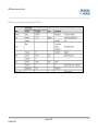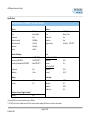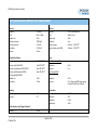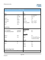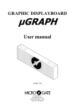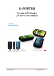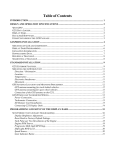
1
VBSS 5/10/20/100 Hz GPS Speed Sensor User Guide VBOX Speed Sensor User Guide Version 2.1 VBOX Speed Sensor User Guide Page 2 of 41 25 March 2013 VBOX Speed Sensor User Guide Contents EC DECLARATION OF CONFORMITY ................................................................................................................................................................................ 5 VBSS SPEED SENSOR OVERVIEW ..................................................................................................................................................................................... 6 FEATURES ...................................................................................................................................................................................................................... 8 STANDARD INVENTORY.................................................................................................................................................................................................. 9 OPERATION ................................................................................................................................................................................................................. 10 INTERFACING WITH THE VBSS ........................................................................................................................................................................................................... 10 POWER ......................................................................................................................................................................................................................................... 10 LED INDICATORS............................................................................................................................................................................................................................. 11 LOCKING ONTO SATELLITES ............................................................................................................................................................................................................... 13 GPS ANTENNA ............................................................................................................................................................................................................................... 13 CONFIGURING THE SPEED SENSOR. (USING THE VBSS SOFTWARE) ................................................................................................................................ 14 INSTALLING THE SOFTWARE .............................................................................................................................................................................................................. 14 RUNNING THE SOFTWARE ................................................................................................................................................................................................................. 14 SETTING UP THE SPEED SENSOR......................................................................................................................................................................................................... 15 Diagnostics.............................................................................................................................................................................................................................. 15 CAN ......................................................................................................................................................................................................................................... 16 Analogue Output .................................................................................................................................................................................................................... 17 Digital Output ......................................................................................................................................................................................................................... 18 Digital Input ............................................................................................................................................................................................................................ 19 Page 3 of 41 25 March 2013 VBOX Speed Sensor User Guide CONFIGURING AND USING THE LAP BEACON OUTPUT .................................................................................................................................................. 20 GPS .......................................................................................................................................................................................................................................... 22 ADAS Functionality ................................................................................................................................................................................................................. 24 Info .......................................................................................................................................................................................................................................... 25 LOADING AND SAVING CONFIGURATION FILES ..................................................................................................................................................................................... 26 Saving a Configuration file...................................................................................................................................................................................................... 26 Loading a Configuration file. .................................................................................................................................................................................................. 26 BUILDING AN INTERFACE CABLE FOR THE VBSS .................................................................................................................................................................................... 27 DIGITAL AND ANALOGUE OUTPUTS .................................................................................................................................................................................................... 27 RS232 CONNECTION....................................................................................................................................................................................................................... 27 LAP INPUT ..................................................................................................................................................................................................................................... 27 GPS COLDSTART ........................................................................................................................................................................................................... 28 UPGRADING THE VBSS FIRMWARE ............................................................................................................................................................................... 29 CAN OUTPUT ............................................................................................................................................................................................................... 30 RS232 / NMEA OUTPUT................................................................................................................................................................................................ 32 SPECIFICATION............................................................................................................................................................................................................. 33 CONNECTION DATA ......................................................................................................................................................................................................................... 40 CONTACT INFORMATION ............................................................................................................................................................................................. 41 Page 4 of 41 25 March 2013 VBOX Speed Sensor User Guide EC Declaration of Conformity We declare that this product has been tested to and meet the requirements of: EC Directive 2004/104/EC “Adapting to Technical Progress Council directive 72/245/EEC, relating to the radio interference (Electromagnetic Compatibility) of vehicles and amending directive 70/156/EEC, on the approximation of the laws of the member states relating to the type-approval of motor vehicles and their trailers.” And has also been assessed, via Technical Construction File, by an independent DTI Competent Body and found to be in conformance with the essential requirements of: EC Directive 89/336/EEC (and amending directives) “Council Directive of 03 May 1989 on the approximation of the laws of the member states relating to electromagnetic compatibility.” DTI Competent Body responsible for issuing certificate of compliance: 3C Test Ltd, Silverstone Technology Park, Silverstone, Northants NN12 8GX Page 5 of 41 25 March 2013 VBOX Speed Sensor User Guide VBSS Speed Sensor Overview 1st Generation Antenna Connector Power LED Satellite LED Data Connector Event LED PIN Out Assignment Page 6 of 41 25 March 2013 VBOX Speed Sensor User Guide 2nd Generation Power LED Data Connector Satellite LED Antenna Connector Event LED PIN Out Assignment Page 7 of 41 25 March 2013 VBOX Speed Sensor User Guide Introduction Racelogic VBSS Speed Sensors feature 5Hz, 10Hz, 20Hz, and 100Hz GPS update rates versions, all units are compatible with the DGPS Basestation for increased positional accuracy. Based on a range of high accuracy GPS engines, the VBSS Speed Sensors can be used for non-contact sensing of velocity providing signal output data on CAN, analogue and digital, allowing easy integration with data loggers and testing applications. The analogue output can be assigned to vehicle speed, lateral acceleration, longitudinal acceleration, or lap beacon marker with user selectable scaling. The digital output can be configured as either a digital speed pulse output or a lap beacon marker. The units all have the same small hardware footprint of only 9cm long, making mounting and transportation easy making the Speed Sensor perfect for automotive testing, motorsport, marine, telematics, and data-logging applications and the IP66 rating means that each unit is water and dustproof, allowing them to be used in a variety of conditions. Features • • • • • • • • • • • • High Performance GPS Receivers: 5 – 100Hz CAN Bus Output of Position, Velocity, Distance, Time, Heading, Height, Vertical Velocity, Longitudinal and Lateral Acceleration, Trigger to zero distance, Trigger time, Trigger speed, Radius of Turn RS232 Serial Output of NMEA, position velocity and time User Configurable Analogue Output User Configurable Digital Output Virtual Lap Beacon Output Compatible with DGPS Basestation Rugged Deutsch ASDD Autosport connector High quality aluminium enclosure IP66 rated: water and dustproof Wide 6.5V – 30V operating range Low current consumption Page 8 of 41 25 March 2013 VBOX Speed Sensor User Guide Standard Inventory Description RLVBSS## Speed Sensor GPS Magnetic Antenna for 5,10 & 20Hz version GPS Magnetic Antenna for 100Hz version VBSS Speed Sensor User manual CD ROM containing VBSS software Supplied separately VBSS Speed Sensor Interface Cable (Analogue / Digital / CAN / Serial / Power) Page 9 of 41 25 March 2013 Qty 1 1 1 1 1 Racelogic Part # VBSS05, VBSS10, VBSS20, or VBSS100 RLVBACS018 RLVBACS001 VBSSMAN CDVBSS 1 RLCAB093 VBOX Speed Sensor User Guide Operation Interfacing with the VBSS If you have purchased a RLCAB49 interface cable, then connect this to the VBSS. The RLCAB49 features connections for power, input and all outputs of the VBSS. Because the VBSS can be used in a number of ways, it is common for the end user to integrate the VBSS connector into their own wiring harness. A mating connector, Deutsch ASDD606-09PN, may be purchased from Racelogic for this purpose. Please see the section of this manual ‘Building an interface cable for the VBSS’. Before connecting power to the VBSS you should connect the GPS antenna, this is because the VBSS will look for a connected GPS antenna and automatically adjust its gain for optimum performance from the connected antenna. For more information about the GPS antenna and antenna placement see the section ‘GPS Antenna’. Power The VBSS can be powered from a wide range of voltage sources including a Vehicle Cigar adapter, a Racelogic Li-ion battery pack or other source provided by the user. The supplied power cable is un-terminated. The maximum operating voltage input must not exceed 30V DC. Failure to observe this could result in damage to the VBSS. NB: That during extended use, the VBSS case may become hot. This is normal; however it is good practice to mount the VBSS in a position where it has sufficient airflow around the case. Page 10 of 41 25 March 2013 VBOX Speed Sensor User Guide LED indicators There are 3 LED indicators on the top of the VBSS to show the status of operation. PWR: Indicates that the VBSS is powered correctly. GREEN LED = OK RED LED = power on, but box not working correctly. SAT: Indicates the number of GPS satellites that the VBSS has in lock. When no satellites are in lock, the SAT LED flashes slowly to indicate that the VBSS is searching for satellites. When one or more satellites are in lock, the LED will pulse the satellite count repeatedly with a short delay. • • • Short RED LED = NO Sats GREEN LED = GPS sat count GREEN / RED LED = GLONAS sat count (if available) The following diagram shows an example of SAT LED pulse sequence. Sequence showing 1 Satellite 1 1 1 1 Sequence showing 4 Satellites Delay 1 2 3 4 Delay 1 2 Sequence showing 0 Satellites Delay (Approximately 1 second ) Delay (Approximately 1 second ) Page 11 of 41 25 March 2013 3 4 VBOX Speed Sensor User Guide EVENT: Flashes in time with the digital pulse output. • Digital Output set to ‘Speed’: If the digital output is set to speed then the GREEN LED will flash in time with speed at a rate of 1/10th of the digital output. • Digital Output set to ‘Lap Pulse’: If the digital output is configured for the Lap Pulse, then the GREEN LED pulses for 1s when the start line is triggered and the EVENT GREEN LED and SATS GREEN LED both light up for 1s if the finish line is triggered. The EVENT LED and the GPS LED will be constantly lit RED for the duration of a coldstart. The EVENT LED will light BLUE when the VBSS has established a good satellite lock on four or more satellites. Page 12 of 41 25 March 2013 VBOX Speed Sensor User Guide Locking onto Satellites If the VBSS is having trouble locking onto satellites then please follow the checklist below for typical solutions: 1) Confirm that the antenna is placed in a position where it has an unobstructed view of the sky. 2) Check the antenna connection with the VBSS; only small amounts of dirt in the socket can cause a significant reduction in signal strength. Also check the cable at the plug and along its length for any damage. 3) Check that the power supply is OK. 4) If possible try another known working antenna, to confirm antenna functionality. 5) Perform a GPS coldstart and then leave the unit powered up in an open static position for at least 15minutes. See ‘GPS Coldstart’. Once the VBSS has locked onto 5 or more satellites then it will be ready for use and will output data on CAN, RS232 and the analogue and digital outputs in accordance with the default settings. The default settings of the CAN bus is shown in the CAN format table at the end of this manual. A CAN ‘.dbc’ data file of this default CAN format is present on the CD, this file can be loaded directly into many CAN based data acquisition systems. The default setting of the Analogue output is Velocity configured to 5V output representing 400Kph. The default setting for the Digital output is Velocity configured to 90 pulses per metre. GPS Antenna The GPS Antenna supplied with the VBSS is a 5v active antenna. For the best possible signal quality, it is important to maintain a clean connection between the antenna and the VBSS. Before fixing the antenna to the VBSS, ensure that there are no dust particles in either connector. Replacement antennas are available by contacting your VBSS distributor. The antenna is a magnetic mounting type for quick and simple mounting to the vehicle roof. For optimum GPS signal reception, make sure that the antenna is fitted to the highest point of the vehicle away from any obstructions that may block satellite reception. The GPS antenna works best with a metal ground plane underneath. (e.g. The Vehicle roof) Please also note that when using any GPS equipment, an unobstructed sky view is important. Objects in the surrounding area such and tall buildings or trees can block the GPS signal causing a reduction or loss in the number of satellites being tracked. Page 13 of 41 25 March 2013 VBOX Speed Sensor User Guide Configuring the Speed Sensor (Using the VBSS Software) Configuration of the VBSS is performed using the setup software supplied with the unit. You will need to power up the VBSS and make a connection from its RS232 to a serial com port or USB socket (via a serial to USB adapter) on your computer. This is most easily achieved using an RLCAB93 cable, which provides a power connection and 9way D type RS232 connection from the VBSS. Installing the software Insert the supplied CD into the CD drive of your computer. An installation box will automatically appear, follow the on screen instructions to complete the installation of the setup software. After installation the CD can be removed and an Icon should have appeared on your desktop that will allow you to start the VBSS software. Running the software First, click on the Options button to select the correct Com port on your computer. Now click the Connect button to enter the VBSS setup screen. NB: After changing any settings in the setup software you will need to press the write button to confirm the changes in the speed sensor. The speed sensor can be used straight from the box and will output digital and analogue signals according to the default settings. These settings can be changed using the VBSS software. The VBSS software allows no other operations apart from setup when connected to a Speed Sensor. Page 14 of 41 25 March 2013 VBOX Speed Sensor User Guide Setting up the Speed Sensor Diagnostics Once the software has finished connecting with the Speed Sensor, a series of setup tabs will become available underneath the main toolbar. The default view is the ‘Diagnostics’ tab as shown on the left, which provides a summary of the Speed Sensor status. Information provided on this tab are as follows: • • • • • • • • • Sats: The number of satellites the Speed Sensor can currently see. UTC Time: The current UTC time. Latitude: The current latitude of the Speed Sensor. Longitude: The current longitude of the Speed Sensor. Speed: The current speed of the Speed Sensor. Analogue Output: The current Analogue output configuration. Digital Output: The current Digital Output configuration. Digital Input: The current Digital Input configuration. GPS Engine Update Rate: The current operating frequency. Page 15 of 41 25 March 2013 VBOX Speed Sensor User Guide CAN The CAN output consists of 7 CAN messages that contain the following data channels: Satellites, Time, Latitude, Longitude, Velocity, Heading, Height, Vertical Velocity, Lap Beacon Output, Longitudinal Acceleration, Lateral Acceleration, Distance and Radius of turn. The default CAN output of the VBSS is shown in the CAN format section at the end of this manual. The following options can be modified from this tab: Baud Rate: The Baud rate can be selected from the drop down menu in the top left of the CAN tab. The user has the choice of four common baud rate values: 125, 250, 500, 1000 Kbit, or can select a custom baud rate by selecting ‘other’. The default baud rate for this output is 500Kbaud. CAN termination Resistance: The internal CAN termination resistance can be enabled or disabled by clicking the ‘Active Termination’ button. The button is highlighted with a blue colour when the CAN termination is active. CAN Identifier value: The CAN tab allows the user to modify the CAN IDs to be transmitted by the Speed Sensor. Default values are the Racelogic standard Identifier values of 0x301, 0x302 …. 0x307, but they can be modified by double clicking on the identifier value. Standard/Extended: To change the identifier format from standard 11bit to extended 29bit tick the ‘Xtd’ box in the corresponding column. Transmission: To switch off or on a CAN message tick or un-tick the box for the corresponding message. NB: After making any changes you must click ‘Write Settings’ for the changes to be programmed into the VBSS. Page 16 of 41 25 March 2013 VBOX Speed Sensor User Guide Analogue Output On this page the user can configure the analogue output of the Speed Sensor to represent the following: Speed: Enter the maximum for the speed range you wish to measure. Default speed is set to 400 kmh. The maximum speed at 5V can be in the range 10 – 1000 kmh. Lap Beacon: When this option is enabled the VBSS will output a 5V pulse for 500ms when a Start/Finish line is crossed. The duration of the pulse in milli Seconds can be adjusted by entering a different value. The polarity of the pulse can be changed to either a rising or falling pulse by clicking the ‘Polarity’ button. The image of the pulse will change to indicate the current polarity configuration. Lateral and & Longitudinal Acceleration: Select the range you wish to use from the pull down list. NB: After making any changes you must click ‘Write Settings’ for the changes to be programmed into the VBSS. Page 17 of 41 25 March 2013 VBOX Speed Sensor User Guide Digital Output The Digital output of the VBSS can be set to one of 3 options, Speed, GPS Sync, or Lap Beacon. Speed: The speed output is configured by changing the number of pulses per metre. Default = 90 pulse per metre => 25 Hz per km/h. GPS Sync: Selecting this option outputs a pulse every second, which is synchronised to the GPS clock. Note: this feature is an optional extra which is not available by default. A GPS engine update is required to allow this to work correctly. Contact [email protected] for more information. Lap Beacon: When this option is enabled the VBSS will output a 5Vpulse for 500ms when a Start/Finish line is crossed. The duration of the pulse in milli Seconds can be adjusted by entering a different value. The polarity of the pulse can be changed to either a rising or falling pulse by clicking the ‘Polarity’ button. The image of the pulse will change to indicate the current polarity configuration. NB: After making any changes you must click ‘Write Settings’ for the changes to be programmed into the VBSS. Page 18 of 41 25 March 2013 VBOX Speed Sensor User Guide Digital Input The digital input is used for the following: If the DIGITAL output is NOT set to LAP BEACON. Brake Trigger Input: Starts the brake stop distance measurement, where the VBSS will calculate a Time and Distance for a Brake Trigger to 0Km/h test. If the DIGITAL output IS set to LAP BEACON. To mark the start/finish line: The digital input of the VBSS can be used to mark a start/finish line and if required a second line. If the vehicle is moving at a speed > 5kmh and a start/finish line successfully marked, the EVENT LED flashes quickly 5 times. NB: The width of the start line and finish line by default is 25m, but can be adjusted via the Windows setup software. To add a 2nd line: There is also a function to add a 2nd line, for example a separate finish line, this is done by pressing and holding the event trigger button for >1.5s. If a second line has been successfully created the SAT and EVENT LEDs flash quickly 5 times. Page 19 of 41 25 March 2013 VBOX Speed Sensor User Guide Configuring and using the lap beacon output The VBSS has the ability to simulate a Lap Beacon signal when a virtual GPS Start/finish or finish line has been crossed. The Lap Beacon output signal can be configured to come out of either the Digital or Analogue output and it is also present as a bit inversion of a bit in a message on the CAN bus output. The Beacon pulse on the analogue and digital channel are opposite polarity, this is to provide two options for a lap beacon pulse. NB: For a Lap beacon pulse to be output by the VBSS it must first be programmed with the position of a Start/finish or Finish line. Setting Start/Finish and Finish Lines This can be done in a number ways: Loading a start/finish line (split file) To load in a previously defined start/finish line, select the following: Options > Configuration > Load Split File. Accepted file types are .DSF and .SPL. Page 20 of 41 25 March 2013 VBOX Speed Sensor User Guide Trigger input: To program the position of a virtual line in the Speed Sensor you must first ensure that you have a connection to the Lap Input (pin 6). This pin should be connected to one side of a momentary switch and the other side of the switch connected to the Ground pin of the VBSS, so that when the switch is pressed the Lap Input pin will be shorted to Ground. To set a Start/finish line: Press and immediately release the Lap input switch as you cross the start finish line. You must be moving >5km/h to do this and following the normal line along the track. The VBSS notes the point and your direction of travel at which you press the switch and then creates a virtual line perpendicular to your line of travel 25m wide. To set a new Start/finish line simple repeat the process above. To set a separate Finish line: press the switch as you cross the Finish line and hold the switch for >1.5 seconds before releasing. After you have set a Start/Finish or Finish line you can view the Latitude and longitude of this line position in the Lap beacon page of the setup software. If the software was already connected then press ‘Connect’ again to refresh the settings. Changing the Width of a Virtual line The Gate width of the Start/finish or Finish line is set in the Lap Beacon page. Change this by entering a new number in the edit box. Then click ‘Write Settings’ to program the new settings into the VBSS. This is a useful feature when two parts of a track may run very close to each other and you do not want the virtual line to be triggered by the wrong part of circuit. Page 21 of 41 25 March 2013 VBOX Speed Sensor User Guide GPS DGPS Mode This gives the user the option to select whether the Speed Sensor uses differential GPS: None: Differential GPS is off. SBAS: The Speed Sensor will use SBAS differential corrections. SBAS differential corrections are received from the nearest Geo-stationary GPS-SBAS satellite, when it is view of the VBSS GPS antenna. RTCM: The Speed Sensor will use RTCM differential corrections. RTCM corrections can be input into the VBSS via a Racelogic telemetry module and a locally placed Base station. Contact Racelogic or your local agent for more details. SMI Level This option allows the user to change the smoothing level of the GPS data. For high dynamic applications such as brake stop testing where less smoothing is required, this should be set to High (High Dynamics). For less dynamic applications which require the GPS data to be smoothed, it should be set to Low (Low dynamics). GPS Engine Update Rate Change the operating frequency of the GPS engine. Minimum Speed (Speed clamping) When this is set speed will be locked to zero below the value eliminating any unwanted speed noise. Page 22 of 41 25 March 2013 VBOX Speed Sensor User Guide Serial Output The Serial Output screen allows the user to configure the format, content and data rate of the serial stream transmitted by the Speed Sensor. Baud Rate: The required serial baud rate can be selected from this drop down menu. Serial Mode: This selects whether the Speed Sensor outputs data in the Racelogic format or the NMEA message format. NMEA Messages If the NMEA message format is selected, more options become available: Update Rate: The update rate of the NMEA messages can be changed using this drop down list. Message Selection: NMEA messages can be selected and deselected for transmission by checking and unchecking the boxes next to each message type. Note: Bandwidth limitations may apply with low Baud rate settings. For example, a high update rate with multiple NMEA messages selected may result in data loss. Page 23 of 41 25 March 2013 VBOX Speed Sensor User Guide ADAS Functionality (Advanced Driver Assistance System) To enable ADAS remote mode the user must power up the Speed Sensor and connect to a PC or Laptop via an RLCAB01 cable and run the Speed Sensor Software. After connecting to the unit, click on the Serial Output tab and select “ADAS remote mode”. Ticking “ADAS remote mode” configures the Speed Sensor to output Racelogic serial data for use with ADAS. The Speed Sensor will calculate its positional and dynamic data and send this information on its serial port which can be transmitted to a local VBOX via radio telemetry module. The addition of this functionality enables the user to operate an ADAS system using the Speed Sensor instead of a second VB3i data logger. For further information on Advanced Driver Assistance Systems, please refer to the Racelogic ADAS manual. Note: This function is currently not available on the 2nd generation of Speed Sensor. Page 24 of 41 25 March 2013 VBOX Speed Sensor User Guide Info The info screen provides information about the connected Speed Sensor. Unit Type: Which unit type is currently connected. Serial number: The serial number of the connected unit. F/W Version: This gives the firmware version of the connected Speed Sensor. GPS Version: This gives the firmware version of the GPS engine in the connected Speed Sensor. Page 25 of 41 25 March 2013 VBOX Speed Sensor User Guide Loading And Saving Configuration files The configurable settings of a VBSS can be saved to a file. The software also allows a configuration file to be loaded enabling quick and easy configuration of the VBSS. Saving a Configuration file. Run the VBSS software Connect a powered VBSS to the PC via a RS232 connection Click the ‘Connect‘ button in the VBSS software to start communications with the VBSS. Configure the VBSS as required. Go to the ‘Options’ menu Highlight the ‘Configuration’ option Then click ‘Save’ The standard Windows save window will appear where you can select a file name and file destination. The file will automatically be given the extension .rlcfg. Loading a Configuration file. Run the VBSS software Connect a powered VBSS to the PC via a RS232 connection Click the ‘Connect‘ button in the VBSS software to start communications with the VBSS. Go to the ‘Options’ menu Highlight the ‘Configuration’ option Then click ‘Load’ The standard Windows Browse window will appear where you can select and load an ‘.rlcfg’ file in to the software. Now click ‘Write Settings’ to apply the configurations from this loaded file into the VBSS Page 26 of 41 25 March 2013 VBOX Speed Sensor User Guide Building an interface cable for the VBSS If you are building your own interface cable for the VBSS it is worthwhile adding the RS232 connection and the Lap input connection. Digital and Analogue outputs It is advisable to use a screened cable on the Analogue and Digital output for the best noise immunity, making sure that the ground is connected to the shielding of the screened cable. RS232 Connection Connect the pins shown in the table to a Female 9 way D-type connector. VBSS Pin 8 Tx 1 Rx 9 9 Way D-Type Pin 2 Rx 3 Tx 5 PIN D Female VIEW FACING SOCKETS Lap Input Connect a momentary switch to the pins shown in the table. VBSS Pin 6 9 Momentary push to make switch Pin 1 signal 2 Ground Page 27 of 41 25 March 2013 VBOX Speed Sensor User Guide GPS Coldstart This forces the GPS engine to reset its downloaded almanac of current satellite position. This can be used if the Speed sensor is having trouble locking onto satellites. This can be caused by the Speed sensor not having been used for a period of time or if it was last used a long distance away from your current point. A GPS satellite Almanac is relevant for about 3- 4weeks, so if it has not been used or updated within that time it can cause the GPS engine to struggle. After performing a GPS Cold start leave the Speed sensor powered up in a static situation where the antenna has an unobstructed view of the skies, for 15 minutes. Once the Speed sensor has downloaded the new almanac it is much quicker to re-acquire satellites in noisy situations such as near trees buildings and bridges. Also it is much quicker to acquire satellites on power-up. To cold start the GPS engine in the Speed sensor using a computer, connect the RS232 port to a computer and run the VBSS set up software which is supplied with the unit. Press ‘Connect’ to start the communications, then select the ‘Cold start’ option, the SAT and EVENT lights will then come on to indicate that the GPS coldstart is being performed. NB: The VBSS main screen and software functions are only applicable to the Speed Sensor. Page 28 of 41 25 March 2013 VBOX Speed Sensor User Guide Upgrading the VBSS Firmware Firmware refers to the operating software inside the VBSS Speed Sensor. The firmware is responsible for all of the functions within the VBSS and from time to time, firmware updates will be released by Racelogic to improve or enhance the way that the VBSS works. The latest firmware will always be available on the Racelogic website: http://www.velocitybox.co.uk/index.php/en/support/39-firmware.html It is recommended to check the web site periodically for updates. The VBSS upgrade files have a “.ruf” file extension. To upgrade the VBSS firmware, download the latest firmware file from the Racelogic web site and copy this file onto your PC. If you have done a full VBSS CD installation then you will have the upgrade programme automatically installed in the Utilities folder of VBSS folder. If not then this can also downloaded from the website. Connect you pc to the VBSS via the VBSS serial lead and apply power to the VBSS. Either ‘double click’ on the ‘.ruf’ upgrade file, which auto runs the Upgrader software, or run the Upgrader software and load in the ‘.ruf’ firmware upgrade file. Then follow the onscreen instructions and the VBSS firmware will be upgraded. At the end of the process power down the VBSS when prompted, before further use During the upgrade process an upgrade log file will have been created. This log file can be emailed to the support address below should any problems arise. If you have any questions regarding the upgrade of the VBSS, please do not hesitate to contact: [email protected] Page 29 of 41 25 March 2013 VBOX Speed Sensor User Guide CAN output The following details the CAN output of the VBSS## ID* Update Rate Data Bytes 1 2 (1)Sats in view 3 4 5 (2) Time since midnight UTC 6 7 8 0x301 100ms (3) Position – Latitude MMMM.MMMMM 0x302 100ms 0x303 100ms (7) Altitude. WGS 84. (Metres) 0x304 100ms (11) Distance from Braketrigger to 0 Kmh (Meters) (12) Longitudinal Accel. (G) (13) Lateral Accel. (G) 0x305 100ms (11) Distance travelled since VBSS reset (Metres) Time taken from brake trigger to 0 Kmh Trigger Speed 0x306 100ms 0x307 100ms (4) Position – Longitude MMMMM.MMMMM (5) Speed. (Knots) (8) Vertical velocity. (M/S) Unused Unused (6) Heading (Degrees) (9) Status (14) Radius of Turn (meters) (15) Position – Latitude DD.DDDDDDD (16) Position – Longitude DD.DDDDDDD *Default IDs shown above. (1) (2) Sats: Time since midnight: (3) Position: (4) Position: (5) (6) (7) Velocity: Heading: Altitude: If Satellites in view < 3 then only Identifier 0x301 transmitted and bytes 2 to 8 are set to 0x00. This is a count of 10ms intervals since midnight UTC. (5383690 = 53836.90 seconds since midnight or 14 hours, 57 minutes and 16.90 seconds). Latitude (mmmm.mmmmm) * 100,000 (311924579 = 51 Degrees, 59.24579 Minutes North). This is a true 32bit signed integer, North being positive. Longitude (mmmmm.mmmmm)* 100,000 (11882246 = 1 Degrees, 58.82246 Minutes West). This is a true 32bit signed integer, West being positive. 0.01 knots per bit. 0.01 per bit. 0.01 meters per bit, signed. Page 30 of 41 25 March 2013 (10) Status2 VBOX Speed Sensor User Guide (8) (9) (10) Vertical Velocity: Status: Status2: (11) (12) (13) (14) (15) Distance: Longitudinal Acc: Lateral Acc: Radius of Turn: Position (16) Position: 0.01 m/s per bit, signed. 8 bit unsigned char. Bit 2 always set. 8 bit unsigned char. Bit 0 is always set, Bit 1 = Lapmarker, Bit 3=brake test started, Bit 4 = Brake trigger active, Bit 5 = DGPS active Distance from brake trigger to zero in meters * 12800. 0.01G per bit, signed. 0.01G per bit, signed. 32-bit signed * 100. Latitude (DD.DDDDDDD) * 10,000,000 This is a true 32bit signed integer, North being positive. Longitude (DD.DDDDDDD) * 10,000,000 This is a true 32bit signed integer, West being positive. Page 31 of 41 25 March 2013 VBOX Speed Sensor User Guide RS232 / NMEA output The RS232 output is present to provide a connection to a computer for configuring the settings of the VBSS through the VBSS setup software. It also can output NMEA format messages. The VBSS can output 8 types of NMEA messages, the most commonly used are GPGGA and GPVTG, the contents of which are shown below. $GPGGA,hhmmss.ss,Latitude,N,Longitude,E,FS,NoSV,HDOP,msl,m,Altref,m,DiffAge,DiffStation*cs<CR><LF> Page 32 of 41 25 March 2013 VBOX Speed Sensor User Guide $GPVTG,cogt,T,cogm,M,sog,N,kph,K*cs<CR><LF> Page 33 of 41 25 March 2013 VBOX Speed Sensor User Guide Specifications 5Hz Speed Sensor (VBSS05): GPS Specifications Velocity Accuracy Units Update rate Maximum velocity Minimum velocity Resolution Latency 0.2 Km/h Km/h or Mph 5 Hz 1000 Mph 0.1 Km/h 0.01 Km/h >160ms Absolute Positioning Accuracy Accuracy w/ SBAS DGPS Accuracy w/ BaseStation RTCM DGPS 5m 95% CEP** 1.8m 95% CEP** 40cm 95% CEP** Update rate Resolution 5 Hz 1.8 cm Heading Resolution Accuracy 0.01° 0.2° Brake stop Accuracy (Trigger Activated) Accuracy N/A Distance Accuracy Units Update rate Resolution Height accuracy Time Accel/Brake Test (MFD): Resolution Accuracy Lap Timing (OLED): Resolution Accuracy Acceleration Accuracy Maximum Resolution Update rate * Not using DGPS and crossing the start/finish line at 100km/h ** 95% CEP (Circle of Error Probable) means 95% of the time the position readings will fall within a circle of the stated radius. Page 34 of 41 25 March 2013 0.05% (<50cm per Km) Metres / Feet 5 Hz 1cm 10 Metres 95% CEP** 0.01 s 0.2 s 0.01 s 0.01 s* 1.00% 4G 0.01 G 5 Hz VBOX Speed Sensor User Guide 10Hz Speed Sensor (VBSS10): GPS Specifications Velocity Accuracy Units Update rate Maximum velocity Minimum velocity Resolution Latency Absolute Positioning Accuracy Accuracy with SBAS DGPS Accuracy w/ Basestation RTCM DGPS Accuracy with Basestation DGPS + GPS Upgrade (RLVBUP30) Update rate Resolution Distance Accuracy Units Update rate Resolution Height accuracy Height accuracy with DGPS 0.05% (<50cm per Km) Metres / Feet 10Hz 1cm 6 Metres 95% CEP** 2 Metres 95% CEP** 3m 95% CEP** 1.8m 95% CEP** 40cm 95% CEP** Time Accel/Brake Test (MFD): Resolution Accuracy 0.01 s 0.1 s 20cm 95% CEP** Lap Timing (OLED): 10 Hz 1.8 cm Resolution Accuracy 0.1 Km/h Km/h or Mph 10 Hz 1000 Mph 0.1 Km/h 0.01 Km/h 41.5ms Heading Resolution Accuracy 0.01° 0.1° Brake Stop Accuracy (Trigger Activated) Accuracy ±20cm Acceleration Accuracy Maximum Resolution Update rate Page 35 of 41 25 March 2013 0.01 s 0.01 s (Not using DGPS and crossing the start/finish line at 100km/h) 0.50% 20 G 0.01 G 10 Hz VBOX Speed Sensor User Guide 20Hz Speed Sensor (VBSS20): GPS Specifications Velocity Accuracy Units Update rate Maximum velocity Minimum velocity Resolution Latency Absolute Positioning Accuracy Accuracy with SBAS DGPS Accuracy w/ Basestation RTCM DGPS Accuracy with Basestation DGPS + GPS Upgrade (RLVBUP30) Update rate Resolution Distance Accuracy Units Update rate Resolution Height accuracy Height accuracy with DGPS 0.1 Km/h Km/h or Mph 20 Hz 1000 Mph 0.1 Km/h 0.01 Km/h 41.5ms 3m 95% CEP** 1.8m 95% CEP** 40cm 95% CEP** 20cm 95% CEP** Time Accel/Brake Test (MFD): Resolution Accuracy Lap Timing (OLED): 20 Hz 1.8 cm Resolution Accuracy Heading Resolution Accuracy 0.01° 0.1° Brake Stop Accuracy (Trigger Activated) Accuracy ±10cm Acceleration Accuracy Maximum Resolution Update rate Page 36 of 41 25 March 2013 0.05% (<50cm per Km) Metres / Feet 20Hz 1cm 6 Metres 95% CEP** 2 Metres 95% CEP** 0.01 s 0.05 s 0.01 s 0.01 s (Not using DGPS and crossing the start/finish line at 100km/h) 0.50% 20 G 0.01 G 20 Hz VBOX Speed Sensor User Guide 100Hz Speed Sensor (VBSS100_V2): GPS Specifications Velocity Accuracy Units Update rate Maximum velocity Minimum velocity Resolution Latency 0.1 Km/h Km/h or Mph 100 Hz 1000 Mph 0.1 Km/h 0.01 Km/h 6.75ms Absolute Positioning Accuracy Accuracy with SBAS DGPS Accuracy with BaseStation RTCM DGPS Update rate Resolution Distance Accuracy Units Update rate Resolution Height accuracy Height accuracy with DGPS 0.05% (<50cm per Km) Metres / Feet 100Hz 1cm 6 Metres 95% CEP** 2 Metres 95% CEP** 3m 95% CEP** >1.8m 95% CEP** 40cm 95% CEP** Time Accel/Brake Test (MFD): Resolution Accuracy 0.01 s 0.01 s 100 Hz 1.8 cm Lap Timing (OLED): Resolution Accuracy Heading Resolution Accuracy 0.01° 0.1° Brake Stop Accuracy (Trigger Activated) Accuracy ±1.8 cm Acceleration Accuracy Maximum Resolution Update rate Page 37 of 41 25 March 2013 0.01 s 0.01 s (Not using DGPS and crossing the start/finish line at 100km/h) 0.50% 20 G 0.01 G 100 Hz VBOX Speed Sensor User Guide Outputs CAN Bus Output Data Rate Data available 125Kbit, 250Kbit, 500Kbit & 1Mbit selectable baud rate. Un-terminated CAN node. Position, vehicle speed, heading, lateral acceleration, longitudinal acceleration, satellite count, time, radius of turn, altitude. RS232 Output Data Rate Data Available 10Hz NMEA $GPGGA and $GPVTG messages at 115200Baud Analogue Output Data Rate Data Available 0 to 5v DC Either Speed, Lateral Acceleration, Longitudinal Acceleration, or Lap Beacon Digital Output Output Data Rate Data Available Low = 0v, High = 5v, 10-1000 pulses per metre, Max frequency 4.4Khz Speed or Lap Beacon Inputs Power Input Voltage range Power 1st Gen = 6.5v – 30v DC 2nd Gen = 7v – 30v DC 3.7w Max (except VBSS05: 2w Max) GPS Antenna 3V Active Antenna (inc) Digital Input Cold Start Activate / Set Lap beacon Position LED Power, Satellite Count, Event Out Page 38 of 41 25 March 2013 VBOX Speed Sensor User Guide Environmental and physical Weight Approx 250g (Except VBSS05: 190g) Operating temp Storage temp -30˚C to +70˚C -40°C to +85°C Size 90mm x 65mm x 31.85mm (for VBSS05/10/20) Connectors Deutsch ASDD Autosport Rated IP66 140mm x 92mm x 31.85mm (for VBSS100-V2) Hardware / Software Support Hardware Software One Year Support Contract Lifetime Support Contract: valid for a minimum of 5 years from the date of purchase and limited to original purchaser. Contract includes telephone / email technical support provided by local VBOX distributor and firmware / software upgrades where applicable. Page 39 of 41 25 March 2013 VBOX Speed Sensor User Guide Connection Data Gen 1 Gen 2 9-PIN Deutsch Connector Pin 1 2 3 4 5 6 7 8 9 I/O I I I/O I/O O I O O I Main Connector (Deutsch Autosport) Function RS232 Rx +8V to +30V Power. Ignition switched feed CAN Low CAN High Analogue Output Lap Marker Input / Brake Trigger Input Speed Pulse / Lap Beacon RS232 Tx Ground Page 40 of 41 25 March 2013 VBOX Speed Sensor User Guide Contact Information Racelogic Ltd Unit 10 Swan Business Centre Osier Way Buckingham MK18 1TB England Tel: +44 (0) 1280 823803 Fax: +44 (0) 1280 823595 Email: [email protected] Web: www.racelogic.co.uk Revision 1 2 3 4 5 Date 12/8/2009 25/9/2009 04/07/2012 24/07/2012 25/03/2013 Description First Draft Software screenshot updates Addition of Speed clamping and removal of Digital input cold start General updates of content and images – addition of Gen 2 unit. Changed RLCAB049 to RLCAB093 on page 14. Page 41 of 41 25 March 2013 Author AM SG RO LN LN