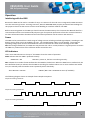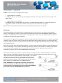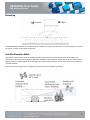
1
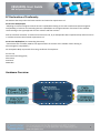
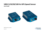
VBSS100SL User Guide 100 Hz Speed Sensor VBSS100SL 100Hz GPS Speed Sensor User Guide 1 VBSS100SL User Guide 100 Hz Speed Sensor Contents EC DECLARATION OF CONFORMITY .................................................................................................................................................................3 HARDWARE OVERVIEW ...................................................................................................................................................................................3 INTRODUCTION ...............................................................................................................................................................................................4 FEATURES ........................................................................................................................................................................................................4 OUTPUTS.........................................................................................................................................................................................................4 STANDARD INVENTORY ...................................................................................................................................................................................4 QUICK-START GUIDE........................................................................................................................................................................................5 FOR SLIP AND PITCH MEASUREMENTS ............................................................................................................................................................................. 5 FOR SLIP AND ROLL MEASUREMENTS .............................................................................................................................................................................. 6 ANTENNA PLACEMENT ................................................................................................................................................................................................ 6 OPERATION .....................................................................................................................................................................................................7 INTERFACING WITH THE VBSS ....................................................................................................................................................................................... 7 POWER .................................................................................................................................................................................................................... 7 LED INDICATORS ........................................................................................................................................................................................................ 7 ANTENNAS ............................................................................................................................................................................................................... 8 MOUNTING .....................................................................................................................................................................................................9 SATELLITE ELEVATION MASK ......................................................................................................................................................................................... 9 HOW TO SETUP DUAL ANTENNA USING VBOX MANAGER .............................................................................................................................10 ANTENNA SEPARATION .............................................................................................................................................................................................. 10 ROLL MODE (OPTIONAL) ............................................................................................................................................................................................ 10 ALIGN ANTENNAS..................................................................................................................................................................................................... 11 LEVEL ANTENNAS ..................................................................................................................................................................................................... 11 SLIP ANGLE TRANSLATION .......................................................................................................................................................................................... 12 ANTENNA OFFSETS ................................................................................................................................................................................................... 12 CONFIGURING THE SPEED SENSOR ................................................................................................................................................................14 HARDWARE CONNECTION .......................................................................................................................................................................................... 14 SOFTWARE CONNECTION ........................................................................................................................................................................................... 14 SETUP OPTIONS.............................................................................................................................................................................................14 GENERAL ................................................................................................................................................................................................................ 14 CAN ...............................................................................................................................................................................................................15 GPS ...............................................................................................................................................................................................................16 SERIAL ...........................................................................................................................................................................................................17 I/O ................................................................................................................................................................................................................17 ANALOGUE OUTPUT ................................................................................................................................................................................................. 17 DIGITAL OUTPUT...................................................................................................................................................................................................... 18 DIGITAL INPUT ......................................................................................................................................................................................................... 18 TESTS ............................................................................................................................................................................................................19 UPGRADING THE VBSS FIRMWARE ................................................................................................................................................................20 CAN OUTPUT .................................................................................................................................................................................................20 RS232 / NMEA OUTPUT .................................................................................................................................................................................22 TECHNICAL SPECIFICATIONS ..........................................................................................................................................................................23 CONNECTION DATA .......................................................................................................................................................................................25 CONTACT INFORMATION ..............................................................................................................................................................................25 2 VBSS100SL User Guide 100 Hz Speed Sensor EC Declaration of Conformity We declare that this product has been tested to and meet the requirements of: EC Directive 2004/104/EC “Adapting to Technical Progress Council directive 72/245/EEC relating to the radio interference (Electromagnetic Compatibility) of vehicles and amending directive 70/156/EEC on the approximation of the laws of the member states relating to the type-approval of motor vehicles and their trailers.” And has also been assessed, via Technical Construction File, by an independent DTI Competent Body and found to be in conformance with the essential requirements of: EC Directive 89/336/EEC (and amending directives) “Council Directive of 03 May 1989 on the approximation of the laws of the member states relating to electromagnetic compatibility.” DTI Competent Body responsible for issuing certificate of compliance: 3C Test Ltd, Silverstone Technology Park, Silverstone, Northants. NN12 8GX Hardware Overview 3 VBSS100SL User Guide 100 Hz Speed Sensor Introduction VBOX Speed Sensor dual antenna (VBSS100SL) is a high accuracy 100Hz GPS/GLONASS system. VBSS100SL combines high level accuracy and test repeatability with the ability to measure slip and pitch/roll angles at 100Hz. Data is present on multiple outputs such as: CAN, RS232, Analogue and Digital lines. The VBSS100SL can be used for non-contact sensing of velocity providing signal output data on CAN, analogue and digital, allowing easy integration with data loggers and testing applications. The analogue output can be assigned to vehicle speed, lateral acceleration, longitudinal acceleration, or lap beacon marker with user selectable scaling. The digital output can be configured as either a digital speed pulse output or a lap beacon marker. The unit has a hardware footprint of only 13cm long, making mounting and transportation easy making the Speed Sensor perfect for automotive testing, motorsport, marine, telematics, and data-logging applications and the IP66 rating means that each unit is water and dustproof, allowing them to be used in a variety of conditions. The VBSS100SL package includes a VBOX Manager, which enables the user to setup the dual antenna separation, change the dynamic modes, level and align the antennas. The speed sensor can be used straight from the box and will output digital and analogue signals according to the default settings. These settings can be changed using the Racelogic Config Software. Features • • • • • • • • • • • • Outputs High Performance GPS/GLONASS Receiver: 100Hz CAN Bus Output includes: Speed, Heading, True Heading, Slip Angle, Pitch or Roll Angle, Slip Translations, Brake Stop Distance, Radius of Turn, Gyro Yaw Rate. RS232 Serial Output of NMEA, position velocity and time User Configurable Analogue Output User Configurable Digital Output Virtual Lap Beacon Output Compatible with DGPS Basestation Rugged Deutsch ASDD Autosport connector High quality aluminium enclosure IP66 rated: water and dustproof Wide 6.5V – 30V operating range Low current consumption Standard Inventory Description RLVBSS100 SL Speed Sensor GPS/GLONASS Magnetic Antenna VBOX Tape Measure VBOX File Manager (Unit Only) Carry Case VBSS Speed Sensor User manual CD ROM containing Racelogic Config Supplied separately VBSS Speed Sensor Interface Cable (Analogue / Digital / CAN / Serial / Power) Qty 1 2 1 1 1 1 1 Racelogic Part # VBSS100 SL RLVBACS156 RLACS091 VBFMAN RLACS106 VBSSMAN CDVBSS 1 RLCAB093-C 4 VBSS100SL User Guide 100 Hz Speed Sensor Quick-start Guide For Slip and Pitch measurements Required equipment (All supplied as standard unless specified): VBSS100SL Connecting Loom (RLCAB093-C) VBOX File Manager + RLCAB005-C 2 x GPS & GLONASS antenna (RLACS156) Tape measure 1. The Speed Sensor unit needs to be mounted flat inside the test vehicle. Failing to do so will have an impact on the accuracy of the calculated slip channels. 2. Mount the GPS/GLONASS antennas on the vehicle roof in-line with the direction of motion, and clear from any obstructions (see image below). For normal operation, place the primary antenna (Socket A) at the rear of the car, and the secondary antenna (Socket B) at the front. All measurements are made from the primary antenna. 3. Make sure the antennas are rotated so the wires exit in the same direction as each other. 4. Accurately measure separation distance to the nearest 5 millimetres, for best accuracy measure from the point at which the cable exits the antenna. 5. Power up VBSS100SL. 6. Connect VBOX Manager to VBSS100SL via Lemo CAN connector on RLCAB093-C. 7. Through VBOX Manager, go into VBOX->DUAL ANTENNA->SEPARATION and enter the separation of the antennas. 8. Allow the unit time to acquire full satellite lock. The number of satellites in view is indicated by the SATS LED; the total of green flashes indicates GPS count, whilst an orange flash indicates the GLONASS satellite count. If the Speed Sensor has not used for a long time, or the location where it is being tested has changed drastically, a GPS coldstart may be required. Note that Racelogic Config software must be used to do this. 5 VBSS100SL User Guide 100 Hz Speed Sensor For Slip and Roll measurements 1. Follow the same steps as ‘Slip & Pitch measurement’ guide, but mount the antennas 90° to the true heading of the vehicle such that the primary antenna (Port A) is on the left hand side of the roof. Minimum recommended separation between the antennas is 0.5m on a level plane, but the greater the separation distance, the better the accuracy. 2. Using the VBOX Manager, go into VBOX->DUAL ANTENNA-> and tick ‘ROLL MODE’. 3. Go into VBOX->DUAL ANTENNA->SEPARATION and enter the separation of the antennas. 4. Try to avoid placing the antennas close to the edge of the roof as this may result in poor dual lock. This is because reflections from the ground will disturb the signals. In order to get a useful slip angle in Roll mode you will need to follow the slip translation guide, found on page 13. The slip angle is calculated from the primary antenna position which in roll mode is off centre and will give inconsistent measurements. Translating this position back to the centre of the car will make the slip measurement consistent when turning both ways. Antenna Placement Whilst installation and use of the VBSS100SL is intended to be fast and simple, careful attention must be paid to placement of the antennas. It is essential that the separation of Antenna B from Antenna A is exactly the same as the separation value set inside the Speed Sensor via the VBOX Manager, or Racelogic config software. If the separation is incorrect, data may not be given or may be inaccurate. The measured distance between the antennas should be the straight-line distance between the antennas regardless of the mounting angle. It is not the 2D distance between the antennas as viewed from above. The supplied tape measure will help ensure an accurate antenna separation. Antenna A is the primary antenna, from which all calculations are based. Therefore the primary antenna should be placed relative to where you wish to make your measurements from. For example, If you wish to make measurements from the centre of the vehicle, this can be achieved by placing the primary antenna at the centre of the vehicle or translating the position using the slip angle translation function in the Vbox Manager. 6 VBSS100SL User Guide 100 Hz Speed Sensor Operation Interfacing with the VBSS Because the VBSS can be used in a number of ways, it is common for the end user to integrate the VBSS connector into their own wiring harness. A mating connector, Deutsch ASDD606-09PN, may be purchased from Racelogic for this purpose. Please see the section of this manual ‘Building an interface cable for the VBSS’. Before connecting power to the VBSS you should connect the GPS antenna, this is because the VBSS will look for a connected GPS antenna and automatically adjust its gain for optimum performance from the connected antenna. For more information about the GPS antenna and antenna placement see the section ‘GPS Antenna’. Power The VBSS can be powered from a wide range of voltage sources including a Vehicle Cigar adapter, a Racelogic Li-ion battery pack or other source provided by the user. The supplied power cable is un-terminated. The maximum operating voltage input must not exceed 30V DC. Failure to observe this could result in damage to the VBSS. NB: That during extended use, the VBSS case may become hot. This is normal; however it is good practice to mount the VBSS in a position where it has sufficient airflow around the case. LED indicators There are 3 LED indicators on the top of the VBSS to show the status of operation. PWR: Indicates that the VBSS is powered correctly. GREEN LED = OK RED LED = power on, but box not working correctly. SAT: Indicates the number of GPS satellites that the VBSS has locked onto. When the VBSS has no satellite lock, the SAT LED flashes slowly to indicate that the VBSS is searching for satellites. When one or more satellites are locked onto, the LED will pulse the satellite count repeatedly with a short delay. - Short RED LED = NO Sats - GREEN / RED LED = GLONASS sat count (if available) The following diagram shows an example of SAT LED pulse sequence. Sequence showing 1 Satellite 1 1 1 1 Sequence showing 4 Satellites Delay 1 2 3 4 Delay 1 2 3 4 Sequence showing 0 Satellites Delay (Approximately 1 second ) Delay (Approximately 1 second ) 7 VBSS100SL User Guide 100 Hz Speed Sensor LED Indicators – Continued EVENT: Flashes in time with the digital pulse output. • Digital Output set to ‘Speed’: If the digital output is set to speed then the GREEN LED will flash in time with speed at a rate of 1/10th of the digital output. • Digital Output set to ‘Lap Pulse’: If the digital output is configured for the Lap Pulse, the EVENT LED shows green for 1s when the start line is triggered. The EVENT LED and SATS LED both show green for 1s if the finish line is triggered. NB: The EVENT LED and the GPS LED will be constantly lit RED for the duration of a coldstart. Antennas The GPS/GLONASS antennas supplied with a RLVBSS100SL are 5V active antennas. For the best possible signal quality, it is important to maintain a clean connection between the antenna and a RLVBSS100SL. Before fixing the antenna to a RLVBSS100SL, ensure that there are no dust particles in either connector. Replacement antennae are available by contacting your VBOX distributor. The antenna is a magnetic mounting type for quick and simple mounting to the vehicle roof. For optimum GPS signal reception, make sure that the antenna is fitted to the highest point of the vehicle away from any obstructions that may block satellite reception. The GPS antenna works best with a metal ground plane underneath (a metallic vehicle roof is perfect for this). Please also note that when using any GPS equipment, a clear sky view is important. Objects in the surrounding area such as tall buildings or trees can block the GPS signal causing a reduction in the number of satellites being tracked, or introducing reflected signals that can decrease the accuracy of the system. Note that clouds and other atmospheric conditions do not affect a RLVBSS100SL’s performance. GPS antennas require a ground plane to operate correctly. This helps to reduce unwanted reflections of the GPS signal caused by nearby objects, and usually the metal roof of a vehicle performs this function. However, if a test requires an antenna to be placed either off the vehicle, or on a vehicle that does not have a metallic roof, a special ground plane antenna must be used. This has an internal ground plane and can operate perfectly without the need for mounting on a metal surface. Ground plane antennas are available from your VBOX distributor. NOTE: VBSS100SL can struggle with maintaining dual lock if the antennas are placed too close to Roof Bars. If a poor mounting position cannot be avoided then the use of elevated GPS/GLONASS ground plane antennas, RLVBACS068 may be required. 8 VBSS100SL User Guide 100 Hz Speed Sensor Mounting The RLVBSS100SL should be mounted as close as possible to the centre of the vehicle. It is also important to mount the sensor so that it is level with the ground. Satellite Elevation Mask This feature can be used to improve GPS signal quality when nearby obstructions like trees and building are reflecting or temporarily obscuring the signal from satellites at low elevation. Raising the mask will cause the GPS engine to ignore satellites below the mask angle, so must be used carefully as it also reduces the total number of received satellites. The elevation mask angle can be changed in the GPS section within VBOX Tools Setup. 9 VBSS100SL User Guide 100 Hz Speed Sensor How to setup Dual Antenna using VBOX Manager The VBOX Manager has been developed to control the operating functions of a VBSS100SL. Within the Dual Antenna menu, select the enable option in order to see the full dual antenna system menu, with a tick shown next to enable. Antenna Separation The most important factor for dual antenna testing is the correct configuration of the separation distance between the two antenna centre points. This allows the VBSS100SL to acquire and maintain dual antenna lock. The physical separation distance between the two antennas should be measured as accurately as possible, and entered in to the Separation option of the Dual Antenna menu. Distances can be incremented in millimetre steps. Note: Whenever the physical antenna separation is altered, this should be changed accordingly within the VBOX Manager. Roll Mode (optional) The VBSS100SL allows the user to separately test roll and pitch measurements during their testing. By default, the VBSS100SL will be setup for pitch determination. If the user wishes to setup their antennas across the width of the car to measure roll angle, then the Roll Mode option must be toggled in the Dual Antenna menu. Click this option to toggle between Pitch Mode (no-tick), and Roll Mode (tick). 1. Primary Antenna (Port A) 2. Secondary Antenna (Port B) 10 VBSS100SL User Guide 100 Hz Speed Sensor Align Antennas To measure the slip angle with the most precision, try and get the alignment of the antennas as close as possible to the centreline of the vehicle. Any residual errors in this alignment can be removed using the AUTO ALIGN feature available in the VBOX Manager. The calibration process requires the driver to drive in a straight line for a short period of time, whilst maintaining a constant speed, greater than 25km/h. Note that any camber on the road or a strong side wind will affect this alignment. Note: You must have dual antenna lock to be able to perform this calibration. Selecting the CLEAR option will remove any offset applied to the slip channel. Level Antennas The Pitch measurement uses the relative height difference between the antennas to calculate the Pitch Angle relative to the ground. If the roof of your vehicle is not perfectly flat in relation to the ground, then this will show up as a Pitch offset. You can automatically remove any offset by performing the AUTO LEVEL feature available on the VBOX Manager. It is recommended that you perform the AUTO LEVEL on a flat, level section of road. Note: You must have dual antenna lock to be able to perform this calibration. Selecting the Clear option will remove any offset applied to the pitch channel. 11 VBSS100SL User Guide 100 Hz Speed Sensor Slip Angle Translation In twin antenna mode you may wish to take slip measurements from other locations on the vehicle, for instance the centre of gravity or slip over the wheels. This can be set using the SLIP TRANSLATION function in the VBOX Manager. The five additional locations are set using longitudinal and lateral offsets from the primary antenna location (antenna 1 in the picture below). Longitudinal translation offsets should be defined as positive when forward of the primary antenna, negative when behind the antenna. Latitudinal translation offsets should be defined as negative when to the left of the antenna, positive when to the right. Gyro assistance: VBSS100SL has an integrated gyroscope which requires the unit to be mounted flat. The Gyro Yaw Rate will be used in the calculated slip channels as the signal to noise ratio is much lower than the GPS derived yaw rate. Therefore no extra noise is added during the slip translation process. 1. Primary Antenna (Port A) 2. Secondary Antenna (Port B) 12 VBSS100SL User Guide 100 Hz Speed Sensor Antenna Offsets In section 1 on the diagram below there is a lateral offset between the primary antenna and the target area for slip measurement. Same again for section 2, there is a longitudinal offset. These offsets will need to be applied to the VBOX Manager (ensure you apply the correct sign when entering the offsets). Each calculated slip point will require two offsets (LAT & LNG) or (lateral & longitudinal) for the VBOX to calculate the channels correctly. Note: if the primary antenna moves the offsets will need to be measured again, for example swapping between a pitch and roll setup. 13 VBSS100SL User Guide 100 Hz Speed Sensor Configuring the Speed Sensor Hardware Connection Configuration of the VBSS is performed using Racelogic Config software. Using the supplied RLCAB093 loom, connect the serial plug to the computers serial port – this can be done via a serial > USB convertor if required. Software Connection Use the drop down list to select the correct COM port that the speed sensor is connected to. Click the connect button to enter the VBSS setup screen. Note: An auto detect message may appear if the baud rate has been changed from the default value– select ‘Yes’ to allow the different baud rates to be scanned. Setup Options 1 General 2 3 4 7 8 9 4 5 4 6 1. Connection - Selected com port, refresh and disconnect buttons. 2. Load/Save - Load/Save settings from/into an .sscfg file. This allows setups to be kept for future use. 3. Language - Select an operating language. 4. Units - Select Distance units (m, ft, km, mi, nmi) and Speed units (kmh, mph, kts, m/s, fts). 5. Diagnostics - Displays live GPS data and basic current setup. GPS Info shows details on fitted GPS engine. 6. Write to unit - After making changes to setup, the write to unit button must be selected to upload settings. 7. GPS Information – Technical details about the GPS engine installed in the connected unit. 8. VBOX Information – Serial number and installed firmware version of connected unit. 9. GPS Coldstart - Clears almanac stored in the GPS engine. Only to be used when struggling to gain SAT lock. 14 VBSS100SL User Guide 100 Hz Speed Sensor CAN The CAN output consists of up to 13 CAN messages. To see details of the default CAN output of the VBSS, go to the CAN format section at the end of this manual. 1 2 1. Baud Rate - The software has four common baud rate values: 1.00 MHz, 500 kHz, 250 kHz or 125 kHz. The user also has the option to select a custom baud rate. 2. CAN termination Resistance - The internal CAN termination resistance can be enabled or disabled here. 2 3 4 1 4 4 1. Send - To switch a CAN message on/off, tick or un-tick the box for the corresponding message. 2. Default / Actual ID – This allows the user to modify the CAN IDs transmitted by the Speed Sensor. Default values are the Racelogic standard ID’s of 0x301, 0x302 …. 0x307. 3. Standard/Extended - To change the identifier format from standard 11bit to extended 29bit tick the ‘Extended’ box in the corresponding column. 4. Parameters – shows which parameters will be sent out in each message. 15 VBSS100SL User Guide 100 Hz Speed Sensor GPS 1 2 4 4 3 1. DGPS Mode - This gives the user the option to select whether the Speed Sensor uses differential GPS: None: Differential GPS is off. SBAS: SBAS differential corrections are received from the nearest Geo-stationary GPS-SBAS satellite. RTCM: RTCM corrections are received by the VBSS via a Racelogic telemetry module and a locally placed Base station. Contact Racelogic or your local agent for more details. 2. GPS Optimisation - This option allows the user to change the sensitivity of the GPS engine. For high dynamic applications such as brake stop testing, this should be set to High. For less dynamic applications, such as steady state speed measurement or coast down testing, this can be set to Low. 3. Slip Angle Settings – Here the user is able to enable or disable twin antenna mode, set roll mode and configure slip translation channel offsets. 4. GPS Settings - Change the update rate of the GPS engine and set a minimum speed output value and elevation mask, if required. For more information on elevation masking, see page 9. 16 VBSS100SL User Guide 100 Hz Speed Sensor Serial The serial output screen allows the user to configure the format, content and data rate of the serial stream transmitted by the Speed Sensor. 1 2 4 1. Mode - This selects whether the Speed Sensor outputs data in the Racelogic format or the NMEA message format. 2. NMEA Messages - If the NMEA message format is selected, more options become available. Baud Rate: The required serial baud rate can be selected from this drop down menu. Update Rate: The update rate of the NMEA messages can be changed using this drop down list. Message Selection: NMEA messages can be selected and deselected for transmission by checking and un-checking the boxes next to each message type. I/O Analogue Output Speed - Enter the maximum for the speed range you wish to measure. Default speed is set to 400 kmh. The maximum speed at 5V can be in the range 10 – 1000 kmh. Lap Pulse - When this option is enabled the VBSS will output a 5V pulse when a Start/Finish line is crossed. The duration of the pulse in milli Seconds can be adjusted by entering a different value. The polarity of the pulse can be changed to either a rising or falling pulse by clicking the ‘Polarity’ button. Lateral / Longitudinal Acceleration - Select the range you wish to use from the pull down list. 17 VBSS100SL User Guide 100 Hz Speed Sensor Digital Output Speed - The speed output is configured by changing the number of pulses per metre. Default = 90 pulse per metre => 25 Hz per km/h. GPS Sync - Selecting this option outputs a pulse every second, which is synchronised to the GPS clock. Note: this feature is an optional extra which is not available by default. A GPS engine update is required to allow this to work correctly. Contact [email protected] for more information. Lap Pulse - When this option is enabled the VBSS will output a 5Vpulse for 300ms when a Start/Finish line is crossed. The duration of the pulse in milliseconds can be adjusted by entering a different value. The polarity of the pulse can be changed to either a rising or falling pulse by selecting the marker next to the desired image. Digital Input Lap Pulse input - To program the position of a virtual line in the Speed Sensor you must first ensure that you have a connection to the Lap Input (pin 6). This pin should be connected to one side of a momentary switch and the other side of the switch connected to the Ground pin of the VBSS, so that when the switch is pressed the Lap Input pin will be shorted to Ground. Set a Start/finish line: Press and immediately release the Lap input switch as you cross the start finish line. You must be moving >5km/h to do this and following the normal line along the track. The VBSS notes the point and direction of travel, then creates a virtual line perpendicular to your line of travel 25m wide. Set a separate Finish line: press hold the switch for >1.5 seconds before releasing. After you have set a Start/Finish or Finish line you can view the Latitude and longitude of this line position in the ‘Tests’ page of the setup software. If the software was already connected then press ‘Connect’ again to refresh the settings. Set a Split line - Press the button twice for a very short period, when this has been marked, the 2nd LED flashes quickly 5 times. The output from the split line should be identical in all respects as the first. To clear all Virtual lines - Press the button shortly once followed by a longer button press (longer than 1.5 seconds). In each case the VBSS will recognise the lead edge of the first pulse as the activation in order to set the associated virtual line at the exact point that the user first presses the switch. Brake Trigger Input - Starts the brake stop distance measurement, where the VBSS will calculate a Time and Distance for a Brake Trigger to 0Km/h test. 18 VBSS100SL User Guide 100 Hz Speed Sensor Tests 1 2 3 1. Deceleration – Here the start and end speed of non-trigger deceleration tests can be configured. Auto Corrected Distance Start Speed – This sets the speed sensor to use the nearest rounded 10km/h speed when the trigger is activated. For example, if the trigger speed was 104km/h then 100km/h would be the nominated start speed for the corrected brake stop distance. Corrected Distance Start Speed - If the auto option is not selected, the user is able to specify a speed value to correct all deceleration tests to. 2. Lap Timing Gate Width – This sets the width of any gates set in the software. This is a useful feature when two parts of a track run very close to each other, or the pit lane is next to the start/finish line, as lowering this value can stop the virtual line being triggered by the incorrect area of the circuit. Time before retrigger – This allows the user to set a number of seconds during which the brake trigger will not be reactive after having been pressed. This is to avoid trigger bounce during tests. CAN Pulse Width – This option controls the duration of the lap time and splits CAN pulse. Other lap timing CAN channels such as Lap Marker, SF crossing pulse or gate crossing pulse mare set to a 1000ms duration, or, the highest analogue or digital pulse duration setting, if greater. Note: For a Lap beacon pulse to be output by the VBSS ensure valid virtual gate(s) have been loaded. 3. Splits – Use the ‘Load all’ button to load a .SPL or .DSF file containing start/finish and split gates. Optionally, load split points, finish line or S/F line separately, using the separate ‘Load’ buttons. Files loaded via these buttons will have the selected information only loaded from them –i.e. a file containing a start/finish gate and 6 splits will only load the start/finish gate when loaded via the Start/Finish ‘Load’ button. 19 VBSS100SL User Guide 100 Hz Speed Sensor Upgrading the VBSS Firmware Firmware refers to the operating software inside the VBSS Speed Sensor. The firmware is responsible for all of the functions within the VBSS and from time to time, firmware updates will be released by Racelogic to improve or enhance the way that the VBSS works. The latest firmware will always be available on the Racelogic website: www.firmware.racelogic.co.uk It is recommended to check the web site periodically for updates. The VBSS upgrade files have a “.ruf” file extension. To upgrade the VBSS firmware, download the latest firmware file from the Racelogic web site and copy this file onto your PC. If you have done a full VBSS CD installation then you will have the upgrade programme automatically installed in the Utilities folder of VBSS folder. If not then this can also downloaded from the website. Connect you pc to the VBSS via the VBSS serial lead and apply power to the VBSS. Either ‘double click’ on the ‘.ruf’ upgrade file, which auto runs the Upgrader software, or run the Upgrader software and load in the ‘.ruf’ firmware upgrade file. Then follow the onscreen instructions and the VBSS firmware will be upgraded. At the end of the process power down the VBSS when prompted, before further use During the upgrade process an upgrade log file will have been created. This log file can be emailed to the support address below should any problems arise. If you have any questions regarding the upgrade of the VBSS, please do not hesitate to contact: [email protected] CAN output The following details the default CAN output from a RLVBSS100SL. Note, this is the Racelogic standard VBOX output, ie. Starting at 0x301 Format Motorola Data Bytes ID* Update Rate 0x301 100ms 0x302 100ms (1) Sats in (2) Time since midnight UTC view (4) Position – Longitude MMMMM.MMMMM 0x303 100ms (7) Altitude. WGS 84. (Metres) 0x304 0x305 0x306 0x307 0x308 100ms 100ms 100ms 100ms 100ms (12) Longitudinal Accel. (G) (15) Trigger Time (S) (18) Radius of Turn (meters) (20) Position – Longitude DD.DDDDDDD (22) Distance from start speed to end speed (Meters) 0x309 100ms 0x30A 100ms (11) Distance from Brake trigger (Meters) (14) Distance travelled since VBOX reset (Metres) Unused (17) Lean Angle (degrees) (19) Position – Latitude DD.DDDDDDD (21) Distance from Brake Trigger (corrected) (Meters) (23) Speed at start of test (24) Speed at end of test (kmh) (kmh) (26) Lap time (s) (27) Split time (s) 0x30B 100ms (29) True Heading (Degrees) (30) Slip Angle (degrees) (31) Pitch Angle (Degrees) 0x30C 100ms (33) Yaw Rate (Degrees/S) (34) Roll Angle (Degrees) 0x30D 100ms (37) Front Left (38) Front Right 1 2 3 4 5 6 7 8 (3) Position – Latitude MMMM.MMMMM (5) Speed. (Knots) (8) Vertical velocity. (M/S) Unused (6) Heading (Degrees) (10) (9) Status Status2 (13) Lateral Accel. (G) (16) Trigger Speed (25) Decel test time (s) unused (28) Status unused (32) Lateral Velocity (Knots) (35) Longitudinal Velocity (Knots) (39) Rear Left (36) Center of Gravity (40) Rear Right 20 VBSS100SL User Guide 100 Hz Speed Sensor CAN output – continued (1) If Satellites in view < 3 then only Identifier 0x301 transmitted and bytes 2 to 8 are set to 0x00. (2) Time since midnight. This is a count of 10ms intervals since midnight UTC. (5383690 = 53836.90 seconds since midnight or 14 hours, 57 minutes and 16.90 seconds). (3) Position, Latitude (mmmm.mmmmm) * 100,000 (311924579 = 51 Degrees, 59.24579 Minutes North). This is a true 32bit signed integer, North being positive. (4) Position, Longitude (mmmmm.mmmmm)* 100,000 (11882246 = 0 Degrees, 58.82246 Minutes West). This is a true 32bit signed integer, West being positive. (5) Velocity, 0.01 knots per bit. (6) Heading, 0.01 per bit. (7) Altitude, 0.01 meters per bit, signed. (8) Vertical Velocity, 0.01 m/s per bit, signed. (9) Status.8 bit unsigned char. Bit 2 always set. (10) Status2, 8 bit unsigned char. Bit 0 is always set, Bit 1 = Lapmarker, Bit 3=brake test started, Bit 4 = Brake trigger active, Bit 5 = DGPS active (11) Distance, 0.000078125 meters per bit, unsigned. Corrected to trigger point (12) Longitudinal Acceleration, 0.01G per bit, signed. (13) Lateral Acceleration, 0.01G per bit, signed. (14) Distance (since reset/powercycle), 0.000078125 meters per bit, unsigned. (15) Time from last brake trigger event. 0.01 Seconds per bit (16) Velocity at brake trigger instant, 0.01 knots per bit (window smoothed over previous 4 samples) (17) Lean Angle, 16-bit signed integer * 100. (18) Radius of Turn 32-bit signed * 100. (19) Position, Latitude (DD.DDDDDDD) * 10,000,000 (519874298 = 51.9874298 Degrees, North). This is a true 32bit signed integer, North being positive. (20) Position, Longitude (DD.DDDDDDD) * 10,000,000 (11882246 = 1.9803743 Degrees, West). This is a true 32bit signed integer, West being positive. (21) Distance, 0.000078125 meters per bit, unsigned. Trigger distance corrected to nearest 10km/h speed (22) Distance, 0.000078125 meters per bit, unsigned. From start speed to end speed –Decel test (23) Speed at start of Decel test, 0.01 knots per bit (24) Speed at end of Decel, test 0.01 knots per bit (25) Time of Decel test . 0.01 Seconds per bit (26) Lap time 0.01 Seconds per bit (27) Split time 0.01 seconds per bit (28) Status. Bit 0 = Start/finish crossing; Bit 1 = Split line crossing (includes start/finish crossing) (29) True Heading of vehicle, 16-bit unsigned integer * 100. (30) Slip Angle, 16-bit signed integer * 100. (31) Pitch Angle, 16-bit signed integer * 100. (32) Lateral Velocity, 16-bit signed integer * 100. (33) YAW rate, 16-bit signed integer*100. (34) Roll Angle, 16-bit signed integer * 100. (35) Longitudinal Velocity, 16-bit signed integer * 100. (36) Centre Of Gravity Slip angle, 16-bit signed integer *100. (37) Front Left, 16-bit signed integer*100. (38) Front Right, 16-bit signed integer*100. (39) Rear Left, 16-bit signed integer*100. (40) Rear Right, 16-bit signed integer*100. 21 VBSS100SL User Guide 100 Hz Speed Sensor RS232 / NMEA output The RS232 output is present to provide a connection to a computer for configuring the settings of the VBSS through the VBSS setup software. It also can output NMEA format messages. The VBSS can output 8 types of NMEA messages, the most commonly used are GPGGA and GPVTG, the contents of which are shown below. $GPGGA,hhmmss.ss,Latitude,N,Longitude,E,FS,NoSV,HDOP,msl,m,Altref,m,DiffAge,Di ffStation*cs<CR><LF> $GPVTG,cogt,T,cogm,M,sog,N,kph,K*cs<CR><LF> 22 VBSS100SL User Guide 100 Hz Speed Sensor Technical Specifications Velocity Distance Accuracy 0.1 Km/h (averaged over 4 samples) Accuracy 0.05% (<50cm per Km) Units Km/h or Mph Units Metres / Feet Update rate 100 Hz Update rate 100Hz Maximum velocity 1000 Mph Resolution 1cm Minimum velocity 0.1 Km/h Height accuracy 6 Metres 95% CEP1 Resolution 0.01 Km/h Height accuracy with DGPS 2 Metres 95% CEP1 Latency 6.75ms Absolute Positioning Accuracy Accuracy with SBAS DGPS Time 3m 95% CEP 2 >1.8m 95% CEP Accuracy with BaseStation RTCM DGPS Update rate 40cm 95% CEP Resolution 1.8 cm 1 Resolution 0.01 s Accuracy 0.01 s 1 100 Hz Heading Acceleration Resolution 0.01° Accuracy 0.50% Accuracy 0.1° Maximum 20 G Resolution 0.01 G Update rate 100 Hz Brake Stop Accuracy (Trigger Activated) Accuracy ±1.8 cm2 Slip Angle Accuracies Pitch/Roll Angle accuracies <0.2° rms at 0.5m antenna separation <0.14° rms at 0.5m antenna separation <0.1° rms at 1.0m antenna separation <0.07° rms at 1.0m antenna separation <0.05° rms at 2m antenna separation <0.035° rms at 2m antenna separation <0.04° rms at 2.5m antenna separation <0.028° rms at 2.5m antenna separation Definitions 1 Circle of Error Probable: 95% of the time the position readings will fall within a circle of the stated radius. 2 Based on <50m brake stop distance. 23 VBSS100SL User Guide 100 Hz Speed Sensor Outputs CAN Bus Output Data Rate 125Kbit, 250Kbit, 500Kbit & 1Mbit selectable baud rate. Software controlled CAN termination. Data available Position, vehicle speed, heading, lateral acceleration, longitudinal acceleration, satellite count, time, radius of turn, altitude, Distance from Trigger, Trigger Time, Trigger Velocity, True Heading. Slip angle, Yaw rate, Pitch/Roll angle, Longitudinal and Lateral Velocity RS232 Output Data Rate Up to 100Hz Data Available NMEA or RL Serial Analogue Output Output Data Rate 0 to 5v DC Data Available Either Speed, Lateral Acceleration, Longitudinal Acceleration, or Lap Beacon Digital Output Output Data Rate Low = 0v, High = 5v, Max. frequency 4.4Khz Data Available Speed or Lap Beacon Inputs Power Input Voltage range 1st Gen = 6.5v – 30v DC / 2nd Gen = 7v – 30v DC Power 3.7w Max GPS Antenna 5V Active Antenna (inc) Digital Input Cold Start Activate / Set Lap beacon Position LED Power, Satellite Count, Event Out Environmental and physical Environmental and physical Weight Approx 250g Operating temperature -30˚C to +70˚C Size 140mm x 92mm x 31.85mm Storage temperature -40°C to +85°C Connectors Deutsch ASDD Autosport Rated IP66 24 VBSS100SL User Guide 100 Hz Speed Sensor Hardware & Software Support Support Hardware One Year Support Contract Software Lifetime Support Contract: Valid for a minimum of 5 years from the date of purchase and limited to the original purchaser. Contract includes: telephone/ email technical support provided by local VBOX Distributor and firmware/ software upgrades (where applicable). Connection Data Main Connector (Deutsch Autosport) Pin I/O 1 2 3 4 5 6 7 8 9 I I I/O I/O O I O O I Function RS232 Rx +8V to +30V Power. Ignition switched feed CAN Low CAN High Analogue Output Lap Marker Input / Brake Trigger Input Speed Pulse / Lap Beacon RS232 Tx Ground Contact Information Racelogic Ltd Unit 10 Swan Business Centre Osier Way Buckingham MK18 1TB England Tel: +44 (0) 1280 823803 Fax: +44 (0) 1280 823595 Email: [email protected] Web: www.racelogic.co.uk 25