1
UM1579
User manual
STEVAL-MKI132V1- BlueMotion motherboard for MEMS
adapter boards
Introduction
The STEVAL-MKI132V1 (BlueMotion) motherboard is designed to provide the user with a
complete ready-to-use platform for the demonstration of MEMS devices mounted on
adapter boards.
This STEVAL-MKI132V1 demonstration board uses an STM32F103TB microcontroller and
an SPBT2532C2.AT Bluetooth® module; it functions as a bridge between the sensor on the
adapter board and the PC. It is possible to connect the BlueMotion to the PC using the
Bluetooth module and using the Unico graphical user interface (GUI), downloadable from
the ST website, or dedicated software routines for customized applications.
This user manual describes the hardware included with the demonstration board and
provides the information required to install and run the demonstration board user interface.
For details regarding the features of each sensor, please refer to the datasheets available for
each individual device.
January 2013
Doc ID 023744 Rev 1
1/26
www.st.com
Contents
UM1579
Contents
1
Demonstration board description . . . . . . . . . . . . . . . . . . . . . . . . . . . . . . 3
2
BlueMotion board installation . . . . . . . . . . . . . . . . . . . . . . . . . . . . . . . . . 8
2.1
Establishing Bluetooth connection . . . . . . . . . . . . . . . . . . . . . . . . . . . . . . . 8
3
Supported MEMS adapter boards . . . . . . . . . . . . . . . . . . . . . . . . . . . . . 12
4
Supported commands . . . . . . . . . . . . . . . . . . . . . . . . . . . . . . . . . . . . . . 13
4.1
Getting started . . . . . . . . . . . . . . . . . . . . . . . . . . . . . . . . . . . . . . . . . . . . . 13
4.2
Supported commands . . . . . . . . . . . . . . . . . . . . . . . . . . . . . . . . . . . . . . . 13
4.3
4.2.1
Commands list and description . . . . . . . . . . . . . . . . . . . . . . . . . . . . . . . 14
4.2.2
Digital output accelerometers: supported commands . . . . . . . . . . . . . . 19
4.2.3
Digital output gyroscopes: supported commands . . . . . . . . . . . . . . . . . 20
4.2.4
Digital output magnetometers: supported commands . . . . . . . . . . . . . . 20
Quick start . . . . . . . . . . . . . . . . . . . . . . . . . . . . . . . . . . . . . . . . . . . . . . . . 21
5
Schematic diagrams . . . . . . . . . . . . . . . . . . . . . . . . . . . . . . . . . . . . . . . . 22
6
Bill of materials . . . . . . . . . . . . . . . . . . . . . . . . . . . . . . . . . . . . . . . . . . . . 23
7
Revision history . . . . . . . . . . . . . . . . . . . . . . . . . . . . . . . . . . . . . . . . . . . 25
2/26
Doc ID 023744 Rev 1
UM1579
1
Demonstration board description
Demonstration board description
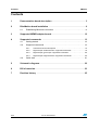
The BlueMotion is a complete demonstration board that allows the demonstration of both
digital and analog MEMS sensors. Thanks to its DIL 24 connector, a wide range of MEMS
adapter boards can be used.
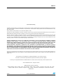
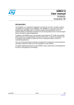
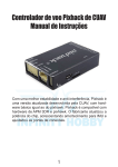
The block diagram of the demonstration board is shown in Figure 1.
Figure 1.
Demonstration board block diagram
MEMS
device
DIL 24
Connector
I2C
STM32F103TB
µC
UART
Bluetooth
Interrupt LEDs
General Purpose LEDs
AM14726V1
As shown in Figure 1, the BlueMotion demonstration board is based on the STM32F103TB
microcontroller and can be connected to the PC through Bluetooth. Data coming from the
MEMS sensor connected to the board can be read through the PC GUI provided with the
board.
The BlueMotion can be flashed with compatible firmware using an SWD connector or a
UART connector. See www.st.com/mems for new firmware releases.
The following steps are required to flash the board using UART:
1.
Connect the BlueMotion to the PC using a UART connector (use the FS and ST pins of
the J2 connector shown in Figure 10).
2.
Set the BOOT0 pin of the DIL 24 device adapter high.
3.
Power up the board.
4.
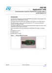
Use the STM32 flash loader utility to establish a UART connection with the BlueMotion.
The recommended settings are shown in Figure 2.
Doc ID 023744 Rev 1
3/26
Demonstration board description
Figure 2.
UM1579
Connecting BlueMotion using UART
AM14752V1
Download the hexadecimal file of the firmware on BlueMotion using the STM32 flash loader
utility. For further details, refer to the utility’s user manual.
Figure 3.
Downloading firmware using UART
AM14753V1
4/26
Doc ID 023744 Rev 1
UM1579
Demonstration board description
Figure 4.
Connecting BlueMotion using UART
AM14754V1
The BlueMotion also integrates one general purpose LED, and two LEDs connected directly
to the interrupt pins of the digital adapters.
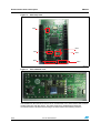
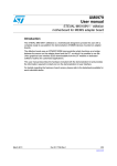
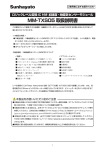
The top view and the bottom view of the full board are shown in Figure 5 and Figure 6
respectively.
Doc ID 023744 Rev 1
5/26
Demonstration board description
Figure 5.
UM1579
Board top view
FT
ref 4
ref 3
ref 1
ref 5
ref 6
ref 2
AM14727V1
Figure 6.
Board bottom view
AM14728V1
The BlueMotion demonstration board can be used with the Unico GUI interface which allows
simple interaction with the sensor. The steps required for establishing a Bluetooth
connection with the board and accessing it are discussed in the following sections.
6/26
Doc ID 023744 Rev 1
UM1579
Demonstration board description
In Figure 5 some of the main components placed on the top layer of the BlueMotion board
are highlighted.
●
The dual power supply connector J1 (Figure 5, ref 1) can be used to supply power in
one of the two possible modes. Pin 2 on must be connected to ground. The board can
be powered with either a 1.5 V supply, e.g. an AA battery, connected to Pin 1 or with a
supply in the range 3.5 V - 6.0 V. connected to Pin 3.
●
The SWD connector J3 can (Figure 5, ref 2) be used to program the BlueMotion board.
●
●
Jumper JP1 allows the user to measure the sensor current consumption by connecting
a multimeter in series with its terminals when a 1.5 V power supply is used (Figure 5,
ref 3).
Jumper JP2 allows the user to measure the sensor current consumption by connecting
a multimeter in series with its terminals when a power supply in the range 3.5 V - 6.0 V
is used (Figure 5, ref 4).
BlueMotion also integrates three LEDs:
●
LED D5 (Figure 5, ref 5) is a general purpose LED and is used to indicate some
firmware states.
●
LEDs D6 and D7 (Figure 5, ref 6) are directly connected to the interrupt pins of the
MEMS digital adapters (if available on the sensor mounted on the adapter board).
Doc ID 023744 Rev 1
7/26
BlueMotion board installation
2
UM1579
BlueMotion board installation
The software package can be downloaded from the st.com website and includes the
following directory structure:
●
FIRMWARE: it contains the source code of the firmware of the BlueMotion board
together with the corresponding binary file that can be flashed to the board.
The section below describes the procedure for establishing a Bluetooth connection with the
BlueMotion board.
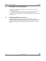
2.1
Establishing Bluetooth connection
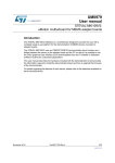
A Bluetooth connection to the BlueMotion board can be established in three steps:
searching the BlueMotion device, pairing it and connecting to it. To search the device, open
the “Bluetooth Places” using the Bluetooth software on your PC and click on “Search
Devices“. The BlueMotion board should appear with the name “eMotion BT”, as shown in
Figure 7.
8/26
Doc ID 023744 Rev 1
UM1579
BlueMotion board installation
Figure 7.
Searching the BlueMotion board
AM14729V1
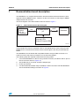
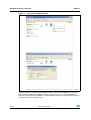
To pair the device right click on the icon “eMotion BT” and select “Pair”. Enter “1234” in the
“Passkey” field in the dialogue-box (shown in Figure 8) and click “OK”.
Doc ID 023744 Rev 1
9/26
BlueMotion board installation
Figure 8.
UM1579
Pairing the BlueMotion board
AM14730V1
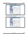
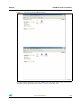
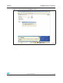
The next step is to connect to the BlueMotion board. Click on the “eMotion BT” icon and
then click on the “Bluetooth Serial Port” icon, as shown in Figure 9. In this example the
board is assigned the port “COM26”. The BlueMotion board is now connected and it can be
accessed through the assigned port.
10/26
Doc ID 023744 Rev 1
UM1579
BlueMotion board installation
Figure 9.
Connecting to the BlueMotion board
AM14731V1
Doc ID 023744 Rev 1
11/26
Supported MEMS adapter boards
3
UM1579
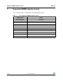
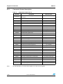
Supported MEMS adapter boards
Table 1 below provides a complete list of supported adapter boards.
Table 1.
12/26
List of supported MEMS adapter boards
Adapter board
Device
STEVAL-MKI089V1
LIS331DLH
STEVAL-MKI105V1
LIS3DH
STEVAL-MKI106V1
LSM303DLHC
STEVAL-MKI107V1
L3G4200D
STEVAL-MKI107V2
L3GD20
STEVAL-MKI108V1
9AXISMODULE v1 [LSM303DLHC + L3G4200D]
STEVAL-MKI108V2
9AXISMODULE v2 [LSM303DLHC + L3GD20]
STEVAL-MKI110V1
AIS328DQ
STEVAL-MKI122V1
LSM330DLC
STEVAL-MKI123V1
LSM330D
STEVAL-MKI303V1
LSM303D
Doc ID 023744 Rev 1
UM1579
4
Supported commands
Supported commands
The microcontroller mounted on the BlueMotion board is equipped with dedicated firmware
that supports a set of commands which allows either the digital or the analog output MEMS
sensor to be controlled and permits the acquisition of the measured data. The firmware also
handles the communication between the board and the PC through a Bluetooth connection.
These features allow the user to easily write their own applications to exploit the capabilities
of the sensor chosen.
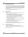
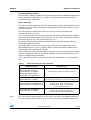
This section describes the commands that are supported by the firmware for the
microcontroller of the BlueMotion demonstration board.
4.1
Getting started
Before using the commands supported by the firmware, the following procedure must be
performed:
1.
Connect the BlueMotion to the PC using Bluetooth.
2.
Launch an application which allows commands to be sent through the virtual serial
port. The remainder of this document assumes the use of the “Microsoft®
HyperTerminal” program available with the Windows® XP operating system.
3.
Create a new connection, enter a name (e.g. “BlueMotion”), and click “OK”.
4.
In the “Connect Using” field, select the Bluetooth serial COM port to which the
BlueMotion has been connected, and click “OK”.
5.
In port settings, set bits per second to 115200, data bits to 8, parity to none, stop bits to
1, and flow control to none. Click “OK”.
6.
On the “HyperTerminal” application window choose “files” > “properties” > “settings”,
then click on the “ASCII Setup” button.
7.
Select “Send line ends with line feeds” and “Echo typed characters locally”.
8.
Click the “OK” button to close the “ASCII Setup” window.
9.
Click the “OK” button to close the “Properties” window.
Once this procedure has been completed the user can utilize the commands described in
the following sections by typing them into the “HyperTerminal” window.
4.2
Supported commands
The firmware supports a wide range of MEMS adapters; the next section reports the
complete list of supported commands (see Table 2) and their description.
Then, the list of commands (split into sections) available for each sensor supported by the
BlueMotion firmware is reported.
Doc ID 023744 Rev 1
13/26
Supported commands
4.2.1
UM1579
Commands list and description
Table 2.
Supported commands list
Command
*setdbXXXVY
*start
*debug
(see Table 3)
Returns the output data in readable text format
(see Table 4)
*Zon
Forces 3-state
*Zoff
Exits from 3-state
*dev
Device name
*ver
Firmware version
*rAA
Accelerometer register read
*wAADD
Accelerometer register write
*grAA
Gyroscope register read
*gwAADD
Gyroscope register write
*mrAA
Magnetometer register read
*mwAADD
Magnetometer register write
e.g.: LIS3DH
e.g.: V1.0
e.g.: RAAhDDh
e.g.: GRAAhDDh
e.g.: MRAAhDDh
(see Table 4)
It gets a single X, Y, and Z data acquisition
Prints the list of MKIs supported
e.g.: MKI105V1
*listdev
Prints the list of devices supported
e.g.: LIS3DH
*echoon
Activates the write verbose mode
e.g.: RAAhDDh
*echooff
Deactivates the write verbose mode
*fifostr
Accelerometer “FIFO Stream” mode enable
st 0 0 0 0 0 0 IR FC FS
Accelerometer “FIFO mode” mode enable
st 0 0 0 0 0 0 IR FC FS
*fifotrg
Accelerometer “Stream-to-FIFO” mode enable
st 0 0 0 0 0 0 IR FC FS
*fiforst
Accelerometer “Reset” mode enable
st 0 0 0 0 0 0 IR FC FS
*gfifostr
Gyroscope “FIFO Stream” mode enable
st 0 0 0 0 0 0 IR FC FS
Gyroscope “FIFO mode” mode enable
st 0 0 0 0 0 0 IR FC FS
*gfifotrg
Gyroscope “Stream-to-FIFO” mode enable
st 0 0 0 0 0 0 IR FC FS
*gfiforst
Gyroscope “Reset” mode enable
st 0 0 0 0 0 0 IR FC FS
*gfifobts
Gyroscope “Bypass-to-FIFO” enable
st 0 0 0 0 0 0 IR FC FS
*fifomde
*gfifomde
14/26
Starts continuous data acquisition
Stops data acquisition
*list
Returned value
Selects firmware according to the adapter
connected
*stop
*single
Note:
Description
IR: interrupt byte; FC: FIFO control register; FS: FIFO source register.
Doc ID 023744 Rev 1
UM1579
Supported commands
Set demonstration board
The command *setdbxxxvy selects the part of the firmware able to handle the adapter board
sensor connected to the board. e.g., in order to select the firmware for the LIS3DH the
command must be: setdb105V1.
Start command
The *start command initiates the continuous data acquisition. When this command is sent to
the device, it returns a string of bytes (plus carriage return and line feed) similar to “st OUT1
OUT2 OUT3 IR BT”.
The first two bytes are always the ASCII char “s” and “t” which correspond to the
hexadecimal values {73h 74h}.
OUT1, OUT2, and OUT3 are the bytes that contain the values measured at device outputs;
if the output data is represented on more than 8 bits, OUT1, OUT2, and OUT3 are split into
two bytes: high byte (e.g.: “XH”) and low byte (e.g.: “XL”).
IR contains the interrupt bytes and BT contains the bytes that describe the state of the
buttons integrated on the board.
Specifically, bit#0 of the “BT” data corresponds to the status of the SW1 button on the
demonstration board: it is set to 1 when the SW1 is pressed (otherwise 0). Bit#1 has the
same behavior but is dedicated to the SW2.
Before sending the *start command, the device must be out from 3-state and some registers
must be configured according to user needs, therefore, *start must be preceded by a *zoff
and some “Register Write” commands.
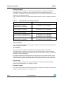
Table 3 shows the format of the string returned for each device when a *start command is
sent.
Table 3.
Returned values for *start command
STEVAL # (device)
Returned value
STEVAL-MKI089V1 (LIS331DLH)
STEVAL-MKI105V1 (LIS3DH)
STEVAL-MKI107V1 (L3G4200D)
STEVAL-MKI107V2 (L3GD20)
STEVAL-MKI110V1 (AIS328DQ)
STEVAL-MKI106V1 (LSM303DLHC)
STEVAL-MKI303V1 (LSM303D)
STEVAL-MKI108V1 (9AXISMODULEv1)
STEVAL-MKI108V2 (9AXISMODULEv2)
STEVAL-MKI122V1 (LSM330DLC)
STEVAL-MKI123V1 (LSM330D)
Note:
s t XH XL YH YL ZH ZL int1 int2 sw1|sw2 \r \n
s t A_XH A_XL A_YH A_YL A_ZH A_ZL M_XH M_XL
M_YH M_YL M_ZH M_ZL A_int1 A_int2 sw1|sw2 \r \n
s t A_XH A_XL A_YH A_YL A_ZH A_ZL
G_XH G_XL G_YH G_YL G_ZH G_ZL
M_XH M_XL M_YH M_YL M_ZH M_ZL
A_int1 A_int2 sw1|sw2 \r \n
s t A_XH A_XL A_YH A_YL A_ZH A_ZL
G_XH G_XL G_YH G_YL G_ZH G_ZL
A_int1 A_int2 G_int1 G_int2 sw1|sw2 \r \n
XH: X axis output high byte (same for Y axis, Z axis, P pressure, and TEMP temperature).
XL: X axis output low byte (same for Y axis, Z axis, P pressure, and TEMP temperature).
Doc ID 023744 Rev 1
15/26
Supported commands
UM1579
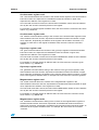
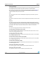
Debug command
The *debug command starts the continuous data acquisition in debug mode. When this
command is sent to the board, it returns the output values measured by the device
formatted in a readable text format. The values shown on the screen correspond to the LSB
data shown as a decimal number.
Table 4 shows the format of the string returned for each device when a *debug command is
sent.
Table 4.
Returned values for *debug command
STEVAL # (device)
Returned value
STEVAL-MKI089V1 (LIS331DLH)
STEVAL-MKI105V1 (LIS3DH)
STEVAL-MKI110V1 (AIS328DQ)
STEVAL-MKI106V1 (LSM303DLHC)
STEVAL-MKI303V1 (LSM303D)
X=XXXXX Y=YYYYY Z=ZZZZZ
AX=XXXXX AY=YYYYY AZ=ZZZZZ
MX=XXXXX MY=YYYYY MZ=ZZZZZ
STEVAL-MKI107V1 (L3G4200D)
STEVAL-MKI107V2 (L3GD20)
P=PPPPP R=RRRRR Y=YYYYY
STEVAL-MKI108V1 (9AXISMODULEV1)
STEVAL-MKI108V2 (9AXISMODULEV2)
AX=XXXXX AY=YYYYY AZ=ZZZZZ
MX=XXXXX MY=YYYYY MZ=ZZZZZ
GX=XXXXX GY=YYYYY GZ=ZZZZZ
STEVAL-MKI122V1 (LSM330DLC)
STEVAL-MKI123V1 (LSM330D)
AX=XXXXX AY=YYYYY AZ=ZZZZZ
GX=XXXXX GY=YYYYY GZ=ZZZZZ
Stop command
The *stop command interrupts any acquisition session that has been started with either the
*start or *debug commands.
Zon and Zoff
The *Zon and *Zoff commands are employed, respectively, to put into 3-state the
STM32F103TB microcontroller mounted on the demonstration board. These commands
allow the isolation of the sensor from the microprocessor and allow the user to interact with
the sensor in a pure analog way.
By default, when the board is first turned on, the lines are in 3-state mode and the user is
required to send the *Zoff command to allow communication between the sensor and the
microcontroller. If Zoff has not been launched, the firmware ignores any other commands.
Device name
The *dev command retrieves the name of the adapter connected to the demonstration
board. The returned value is, for example, “LIS3DH”.
Firmware version
The *ver command queries the demonstration board and returns the version of the firmware
loaded in the microprocessor, for example, “V1.0”.
16/26
Doc ID 023744 Rev 1
UM1579
Supported commands
Accelerometer register read
The *rAA command allows the contents of the accelerometer registers in the demonstration
board to be read. AA, expressed as a hexadecimal value and written in upper case,
represents the address of the register to be read.
Once the read command is issued, the board returns RAAhDDh, where AA is the address
sent by the user and DD is the data present in the register.
For example, to read the register at address 0x20, the user issues the command *r20, which
returns, e.g., R20hC7h.
Accelerometer register write
The *wAADD command allows writing to the contents of the accelerometer registers of the
demonstration board. AA and DD, expressed as hexadecimal values and written in upper
case, represent, respectively, the address of the register and the data to be written. For
example, to write 0xC7 to the register at address 0x20, the user issues the command
*w20C7.
Gyroscope register read
The *grAA command allows the contents of the gyroscope registers of the demonstration
board to be read. AA, expressed as hexadecimal value and written in upper case,
represents the address of the register to be read.
Once the read command is issued, the board returns GRAAhDDh, where AA is the address
sent by the user and DD is the data present in the register.
For example, to read the register at address 0x20, the user issues the command *gr20,
which returns, e.g., GR20hC7h.
Gyroscope register write
The *gwAADD command allows writing to the contents of the gyroscope registers of the
demonstration board. AA and DD, expressed as hexadecimal values and written in upper
case, represent, respectively, the address of the register and the data to be written. To write
0xC7 to the register at address 0x20, for example, the user issues the command *gw20C7.
Magnetometer register read
The *mrAA command allows the contents of the magnetometer registers in the
demonstration board to be read. AA, expressed as a hexadecimal value and written in upper
case, represents the address of the register to be read.
Once the read command is issued, the board returns MRAAhDDh, where AA is the address
sent by the user and DD is the data present in the register.
For example, to read the register at address 0x00, the user issues the command *mr00,
which returns, e.g., MR00h10h.
Magnetometer register write
The *mwAADD command allows writing to the contents of the magnetometer registers of
the demonstration board. AA and DD, expressed as hexadecimal values and written in
upper case, represent, respectively, the address of the register and the data to be written. To
write 0x20 to the register at address 0x01, for example, the user issues the command
*mw0120.
Doc ID 023744 Rev 1
17/26
Supported commands
UM1579
Single acquisition
The *single command may be used to read just one set of data. It requires the sensor to be
well configured and once invoked, returns the read values of one data sample.
The format of the returned value is exactly the same as the *debug command (Table 4), in
fact, the *debug command is used for continuous data acquisition purposes whereas a
*single command returns just one set of data.
List
The *list command returns the list of MKI adapters supported by the firmware, printed in
ASCII format.
Listdev
The *listdev command returns the list of devices supported by the firmware, printed in ASCII
format.
Echo on
The *echoon command is used to activate the write command verbose mode. Once this
command is launched, after every write command the firmware automatically performs also
a read of the register just written. This function is useful to check if the write has succeeded.
For instance, if the *echoon command is launched, after a *w2027 it results R2027.
Echo off
The *echooff command stops the write command verbose mode.
Accelerometer FIFO Stream mode enable
The *fifostr command is used to enable the accelerometer FIFO Stream mode. For more
details see the AN3308 application note.
Accelerometer FIFO mode enable
The *fifomde command is used to enable the accelerometer FIFO mode. For more details
see the AN3308 application note.
Accelerometer Stream-to-FIFO mode enable
The *fifotrg command enables the accelerometer Stream-to-FIFO mode. For more details
see the AN3308 application note.
Accelerometer FIFO Reset enable
The *fiforst command enables the accelerometer FIFO Reset mode. For more details see
the AN3308 application note.
Gyroscope FIFO Stream mode enable
The *fifostr command is used to enable the gyroscope FIFO Stream mode.
Gyroscope FIFO mode enable
The *gfifomde command is used to enable the gyroscope FIFO mode.
18/26
Doc ID 023744 Rev 1
UM1579
Supported commands
Gyroscope Stream-to-FIFO mode enable
The *gfifotrg command enables the gyroscope Stream-to-FIFO mode.
Gyroscope FIFO Reset enable
The *gfiforst command enables the gyroscope FIFO Reset mode.
Gyroscope FIFO Bypass-to-Stream enable
The *gfifobts command enables the gyroscope Bypass-to-Stream mode.
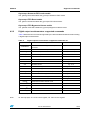
4.2.2
Digital output accelerometers: supported commands
Table 5 below lists the commands supported by the devices/demonstration boards including
a digital output accelerometer.
Table 5.
Digital output accelerometers: supported commands list
Command
*setdbXXXVY
*start
*debug
Description
Selects firmware according to the adapter
connected
Starts continuous data acquisition
(see Table 3)
Returns the output data in readable text format
(see Table 4)
*stop
Stops data acquisition
*Zon
Forces 3-state
*Zoff
Exits from 3-state
*dev
Device name
*ver
Firmware version
*rAA
Accelerometer register read
*wAADD
Accelerometer register write
*single
*list
Returned value
e.g.: LIS3DH
e.g.: V1.0
e.g.: RAAhDDh
(see Table 4)
It gets a single X, Y, and Z data acquisition
Prints the list of MKIs supported
e.g.: MKI105V1
*listdev
Prints the list of devices supported
e.g.: LIS3DH
*echoon
Activates the write verbose mode
e.g.: RAAhDDh
*echooff
Deactivates the write verbose mode
*fifostr(1)
Accelerometer “FIFO Stream” mode enable
st 0 0 0 0 0 0 IR FC FS
*fifomde(1)
Accelerometer “FIFO mode” mode enable
st 0 0 0 0 0 0 IR FC FS
*fifotrg(1)
Accelerometer “Stream-to-FIFO” mode enable
st 0 0 0 0 0 0 IR FC FS
*fiforst(1)
Accelerometer “Reset” mode enable
st 0 0 0 0 0 0 IR FC FS
1. Available only for devices with embedded FIFO.
Note:
IR: interrupt byte; FC: FIFO control register; FS: FIFO source register.
Doc ID 023744 Rev 1
19/26
Supported commands
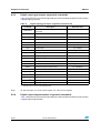
4.2.3
UM1579
Digital output gyroscopes: supported commands
Table 6 below lists the commands supported by the devices/demonstration boards including
a digital output gyroscope:
Table 6.
Digital output gyroscopes: supported commands list
Command
*setdbXXXVY
*start
*debug
Description
Selects firmware according to the adapter
connected
Starts continuous data acquisition
(see Table 3)
Returns the output data in readable text format
(see Table 4)
*stop
Stops data acquisition
*Zon
Forces 3-state
*Zoff
Exits from 3-state
*dev
Device name
*ver
Firmware version
*grAA
Gyroscope register read
*gwAADD
Gyroscope register write
*single
*list
Returned value
e.g.: LIS3DH
e.g.: V1.0
e.g.: GRAAhDDh
(see Table 4)
It gets a single X, Y, and Z data acquisition
Prints the list of MKIs supported
e.g.: MKI105V1
*listdev
Prints the list of devices supported
e.g.: LIS3DH
*echoon
Activates the write verbose mode
e.g.: RAAhDDh
*echooff
Deactivates the write verbose mode
*gfifostr(1)
Gyroscope “FIFO Stream” mode enable
st 0 0 0 0 0 0 IR FC FS
Gyroscope “FIFO mode” mode enable
st 0 0 0 0 0 0 IR FC FS
*gfifotrg(1)
Gyroscope “Stream-to-FIFO” mode enable
st 0 0 0 0 0 0 IR FC FS
*gfiforst(1)
Gyroscope “Reset” mode enable
st 0 0 0 0 0 0 IR FC FS
*gfifobts(1)
Gyroscope “Bypass-to-FIFO” enable
st 0 0 0 0 0 0 IR FC FS
*gfifomde(1)
1. Available only for devices with embedded FIFO.
Note:
IR: interrupt byte; FC: FIFO control register; FS: FIFO source register.
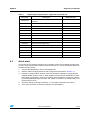
4.2.4
Digital output magnetometers: supported commands
Table 7 below lists the commands supported by the devices/demonstration boards including
a digital output magnetometer:
20/26
Doc ID 023744 Rev 1
UM1579
Supported commands
Table 7.
Digital output magnetometer: supported commands list
Command
*setdbXXXVY
*start
*debug
Starts continuous data acquisition
(see Table 3)
Returns the output data in readable text format
(see Table 4)
Stops data acquisition
*Zon
Forces 3-state
*Zoff
Exits from 3-state
*dev
Device name
*ver
Firmware version
*mrAA
Pressure sensor register read
*mwAADD
Pressure sensor register write
*list
Returned value
Selects firmware according to the adapter
connected
*stop
*single
4.3
Description
It gets a single X, Y, and Z data acquisition
Prints the list of MKIs supported
e.g.: LIS3DH
e.g.: V1.0
e.g.: MRAAhDDh
(see Table 4)
e.g.: MKI105V1
*listdev
Prints the list of devices supported
e.g.: LIS3DH
*echoon
Activates the write verbose mode
e.g.: MRAAhDDh
*echooff
Deactivates the write verbose mode
Quick start
This section shows the basic sequence of commands, based on the LIS3DH accelerometer,
to start a data communication session and to retrieve the X, Y, and Z acceleration data from
the demonstration board:
1.
Connect the BlueMotion to the PC using Bluetooth.
2.
Start the “Microsoft HyperTerminal” and configure it as described in Section 4.1.
3.
Inside the “HyperTerminal” window, enter the command *setdb105v1 (supposing the
LIS3DH adapter board is used, for other adapters see the relevant datasheets to check
the register configuration), enter the command *Zoff to enable the control of the device
by the STM32F103TB microcontroller, and *w2047 to switch on the LIS3DH and to set
the data rate to 50 Hz.
4.
Send the *debug command to get the X, Y, and Z data measured by the sensor.
5.
Send *stop to end the continuous acquisition and visualization.
Doc ID 023744 Rev 1
21/26
ANT_BLUETOOTH
Vbat (LiPo)
C7
1uF
VDD_3_3V
C3
100nF
1
2
3
4
3
1
EN
Vin
U2
L6920DC
Gnd
Doc ID 023744 Rev 1
D4
D1
RF_GND
ANT
C10
33nF
C1
47uF
VDD JP2
50 OHM PCB Line
R6
130R
R3
130R
4
lds3985xx30
5
Vout
8
7
6
5
BYPASS
FB
OUT
LX
LBI
LBOn GND
REF SHDN
U1
JP1
1
2
C9
2.2uF
BT_Module SPBT2532C2.AT
GND
ANT
GND
GPIO_04
GPIO_03
GPIO_02
GPIO_01
U4
Vbat (1.5V)
C2
47uF
V_IN
BOOT
RESET
CTS
RTS
RXD
TXD
8
9
10
11
12
13
14
R8 R0
Not Mounted
CTS
RTS
RXD
TXD
VDD
R7
4K7
VDD
RESET_BT
Bluetooth Module
Power Supply
Dual Power Supply
1
2
3
J1
R5
10K
SWDIO
SWCLK
NRST
C13
100nF
3
Cosc2
18pF
1 OSCOUT
VDD
1
2
3
4
5
6
7
8
9
R1
4.7K
VDD
R9
10K
I2C_SDA
I2C_SCL
R2
4.7K
Vdd_3
OSC_IN/PD0
OSC_OUT/PD1
NRST
Vssa
Vdda
WKUP/PA0
PA1
PA2/
USART2_TX
J2
24
23
22
21
20
19
18
17
16
15
14
13
D5
R13
130R
VDD
Header 12Header 12
1
2
3
4
5
6
7
8
9
10
11
12
J4
Vdd_2
Vss_2
PA13/SWDIO
PA12
PA11
PA10/USART1_RX
PA9/USART1_TX
PA8
Vdd_1
27
26
25
24
23
22
21
20
19
STM32F103TB
U3
VDD
D6
D7
R12
130R
R11
SWDIO
C6
100nF
INT1
PD
FS
ST
INT2
GP_GPIO
I2C_SDA
I2C_SCL
GP_GPIO1
PD
FS
ST
INT2
INT1
BOOT0
INT2
130R
C5 100nF
VDD
24
23
22
21
20
19
18
17
16
15
14
13
DIL24 Device Adapter
18
17
16
15
14
13
12
11
10
Osc1
16MHz
1uF
RTS
CTS
RXD
C4
100nF
OUT1
OUT2
OUT4
OUT3
Vdd_dut
Vss_1
PB2
PB1/ADC9
PB0/ADC8
PA7/ADC7
PA6/ADC6
PA5/ADC5
PA4/ADC3
PA3/USART2_R X
Cosc1
18pF
OSCIN
R10
1M
C8
VDD
OSCIN
OSCOUT
NRST
C12 10nF
C11
4.7uF
Microcontroller
Connectors
Vbat (LiPo)
Vbat (1.5V)
SWD Connector
1
2
3
4
5
VDD
PA14/SWCLK
PA15
PB3
PB4
PB5
PB6/I2C1_SCL
PB7/I2C1_SDA
BOOT0
Vss_3
7
6
5
4
3
2
1
Current_Measure
Vdd_dut
Inductor
10uH
L1
J3
R4
10K
VDD
SWCLK 28
GP_GPIO129
30
31
GP_GPIO32
33
34
BOOT0 35
36
0
1
2
2
INT1
4
2
22/26
BOOT0
5
GP_led
VDD_3_3V
Schematic diagrams
UM1579
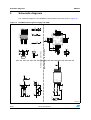
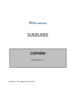
Schematic diagrams
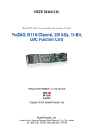
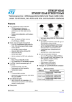
The schematic diagrams of the BlueMotion demonstration board are shown in Figure 10.
Figure 10. BlueMotion board (power supply and USB)
GP_led
OUT1
OUT2
OUT4
OUT3
RESET_BT
TXD
1
AM14732V1
UM1579
6
Bill of materials
Bill of materials
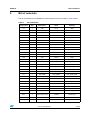
The bill of materials for the BlueMotion demonstration board is provided in Table 8 below.
Table 8.
Bill of materials
Component
Qty.
Description
Value
Package
C1
1
CAP
47 μF
0805
C2
1
CAP
47 μF
0805
C3
1
CAP
100 nF
0402
C4
1
CAP
100 nF
0402
C5
1
CAP
100 nF
0402
C6
1
CAP
100 nF
0402
C7
1
CAP
1 μF
0402
C8
1
CAP
1 μF
0402
C9
1
CAP
2.2 μF
0402
C10
1
CAP
33 nF
0402
C11
1
CAP
4.7 μF
0603
C12
1
CAP
10 nF
0402
C13
1
CAP
100 nF
0402
Cosc1
1
CAP
18 pF
0402
Cosc2
1
CAP
18 pF
0402
D1
1
LED_SMD
LED_SMDg
LED_SMD_0603
D4
1
LED_SMD
LED_SMDr
LED_SMD_0603
D5
1
LED_SMD
LED_SMDg
LED_SMD_0603
D6
1
LED_SMD
LED_SMDg
LED_SMD_0603
D7
1
LED_SMD
LED_SMDr
LED_SMD_0603
J1
1
MHDR1X3
Dual power supply
HDR1X3
J4
1
Header 12
HDR1X12
J2
1
Header 12
Header _13_to_24
J3
1
Header 5
SWD connector
MHDR1X5
JP1
1
CON2
Current_measure
Header 1x2 2 mm
JP2
1
CON2
Current_measure
Header 1x2 2 mm
L1
1
Inductor
Inductor
1210(2)
Osc1
1
Ceramic SMD
crystal 3.2x2.5 mm
16 MHz
Ceramic SMD crystal
3.2x2.5 mm
R1
1
Res1
4.7 KΩ
0402
R2
1
Res1
4.7 KΩ
0402
Doc ID 023744 Rev 1
23/26
Bill of materials
UM1579
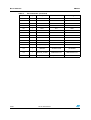
Table 8.
24/26
Bill of materials (continued)
Component
Qty.
Description
Value
Package
R3
1
Res1
130R
0402
R4
1
Res1
10 KΩ
0402
R5
1
Res1
10 KΩ
0402
R6
1
Res1
130R
0402
R7
1
Res1
4K7
0402
R9
1
Res1
10 KΩ
0603
R10
1
Res1
1 MΩ
0402
R11
1
Res1
130R
0402
R12
1
Res1
130R
0402
R13
1
Res1
130R
0402
U1
1
L6920
L6920DC
L6920DC
U2
1
Component_1
lds3985xx30
SOT23-5
U3
1
STM32F103TB_VF
QFPN36
STM32F103TB
VFQFPN36
U4
1
Bluetooth_module
BT_module
SPBT2532C2.AT
SPBT25532C2.AT
U5
1
ANT_BLUETOOTH
ANT_BLUETOOTH
Antenna Johanson
Doc ID 023744 Rev 1
UM1579
7
Revision history
Revision history
Table 9.
Document revision history
Date
Revision
29-Jan-2013
1
Changes
Initial release.
Doc ID 023744 Rev 1
25/26
UM1579
Please Read Carefully:
Information in this document is provided solely in connection with ST products. STMicroelectronics NV and its subsidiaries (“ST”) reserve the
right to make changes, corrections, modifications or improvements, to this document, and the products and services described herein at any
time, without notice.
All ST products are sold pursuant to ST’s terms and conditions of sale.
Purchasers are solely responsible for the choice, selection and use of the ST products and services described herein, and ST assumes no
liability whatsoever relating to the choice, selection or use of the ST products and services described herein.
No license, express or implied, by estoppel or otherwise, to any intellectual property rights is granted under this document. If any part of this
document refers to any third party products or services it shall not be deemed a license grant by ST for the use of such third party products
or services, or any intellectual property contained therein or considered as a warranty covering the use in any manner whatsoever of such
third party products or services or any intellectual property contained therein.
UNLESS OTHERWISE SET FORTH IN ST’S TERMS AND CONDITIONS OF SALE ST DISCLAIMS ANY EXPRESS OR IMPLIED
WARRANTY WITH RESPECT TO THE USE AND/OR SALE OF ST PRODUCTS INCLUDING WITHOUT LIMITATION IMPLIED
WARRANTIES OF MERCHANTABILITY, FITNESS FOR A PARTICULAR PURPOSE (AND THEIR EQUIVALENTS UNDER THE LAWS
OF ANY JURISDICTION), OR INFRINGEMENT OF ANY PATENT, COPYRIGHT OR OTHER INTELLECTUAL PROPERTY RIGHT.
UNLESS EXPRESSLY APPROVED IN WRITING BY TWO AUTHORIZED ST REPRESENTATIVES, ST PRODUCTS ARE NOT
RECOMMENDED, AUTHORIZED OR WARRANTED FOR USE IN MILITARY, AIR CRAFT, SPACE, LIFE SAVING, OR LIFE SUSTAINING
APPLICATIONS, NOR IN PRODUCTS OR SYSTEMS WHERE FAILURE OR MALFUNCTION MAY RESULT IN PERSONAL INJURY,
DEATH, OR SEVERE PROPERTY OR ENVIRONMENTAL DAMAGE. ST PRODUCTS WHICH ARE NOT SPECIFIED AS "AUTOMOTIVE
GRADE" MAY ONLY BE USED IN AUTOMOTIVE APPLICATIONS AT USER’S OWN RISK.
Resale of ST products with provisions different from the statements and/or technical features set forth in this document shall immediately void
any warranty granted by ST for the ST product or service described herein and shall not create or extend in any manner whatsoever, any
liability of ST.
ST and the ST logo are trademarks or registered trademarks of ST in various countries.
Information in this document supersedes and replaces all information previously supplied.
The ST logo is a registered trademark of STMicroelectronics. All other names are the property of their respective owners.
© 2013 STMicroelectronics - All rights reserved
STMicroelectronics group of companies
Australia - Belgium - Brazil - Canada - China - Czech Republic - Finland - France - Germany - Hong Kong - India - Israel - Italy - Japan Malaysia - Malta - Morocco - Philippines - Singapore - Spain - Sweden - Switzerland - United Kingdom - United States of America
www.st.com
26/26
Doc ID 023744 Rev 1