1
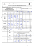
Application Note
SmartScan50
Volume and Custom Flume
Configuration
Version 1.1
June 2011
This document contains proprietary information that is the sole property of Solid Applied
Technologies Ltd. The document is submitted to the recipient for his use only. By receiving
this document; the recipient undertakes not to duplicate or to disclose, in part or the
whole, any of the information contained herein; to any third party; without a-priory
written permission from Solid Applied Technologies Ltd.
________________________________________1 of 13 _____________________________________
Solid Applied Technologies Ltd.
www.solidAT.com
40, Hutzot Hayozer,
[email protected]
Ashkelon 78170, Israel
Tel: +972 (8) 674 4051
Table of Contents
1. SCOPE.................................................................................................................................................. 3
2. OBJECTIVES ......................................................................................................................................... 3
3. METHOD FOR MEASURING VOLUME ................................................................................................... 3
4. MANUAL INSERTION OF STRAPPING TABLE.......................................................................................... 5
5. SEMI-AUTOMATIC INSERTION OF THE STRAPPING TABLE .................................................................... 6
6. LOOP-CURRENT CONFIGURATION FOR VOLUME.................................................................................. 8
7. CONFIGURING SPECIAL VESSEL SHAPES ............................................................................................... 9
8. WEIGHT CALCULATIONS ...................................................................................................................... 9
9. FLOW MEASUREMENT OF CUSTOM FLUME ....................................................................................... 10
10. LOOP-CURRENT CONFIGURATION FOR CUSTOM FLUMES ................................................................ 12
APPENDIX A: VOLUME CALCULATIONS .................................................................................................. 13
________________________________________2 of 13 _____________________________________
Solid Applied Technologies Ltd.
www.solidAT.com
40, Hutzot Hayozer,
[email protected]
Ashkelon 78170, Israel
Tel: +972 (8) 674 4051
1. SCOPE
This document describes the configuration procedure of SmartScan50 unit for volume measurement
and for flow measurement in custom flumes. The document should be read jointly with the user manual
of SmartScan systems.
2. OBJECTIVES
Familiarize the user of SmartScan50 with:
• Configuration methods for making volume and flow measurements.
• Configuring volume measurements using manual insertion of strapping tables.
• Configuring volume measurements using semi-automatic insertion of strapping tables.
• Setting 4-20mA configurations for volume and for custom flow measurements.
• Weight calculations using the “K factor”.
3. METHOD FOR MEASURING VOLUME
Ultrasonic level sensors measure DISTANCE between the sensor and surface of the target. If distance
between sensor and bottom of tank is known (TOTAL HEIGHT), SmartScan50 can also calculate LEVEL.
For VOLUME, the user should configure SmartScan50 to map between LEVEL and VOLUME.
SmartScan50 provides for a mapping table (also known as strapping table) of up to 24 points. The user
enters a minimum of 8 points and for each point the user defines LEVEL and corresponding VOLUME.
The drawing below illustrates the insertion of LEVEL points into the strapping table:
Sensor
P8 Level = 8 meter
Volume = 9600 Liter
P7 Level = 7 meter
Volume = 8400 Liter
P6 Level = 6 meter
Volume = 7200 Liter
P5 Level = 5 meter
Volume = 6000 Liter
P4 Level = 4 meter
Volume = 4800 Liter
P3 Level = 3 meter
Volume = 3600 Liter
P2 Level = 2 meter
Volume = 2400 Liter
P1 Level = 1 meter
Volume = 1200 Liter
TOTAL HEIGHT
10 meter
________________________________________3 of 13 _____________________________________
Solid Applied Technologies Ltd.
www.solidAT.com
40, Hutzot Hayozer,
[email protected]
Ashkelon 78170, Israel
Tel: +972 (8) 674 4051
The strapping table is set by entering point by point from the low level and up. Each point involves three
main steps and step 3 consists of two entries:
Step
1
2
3
3.1
3.2
Description
Point number
LEVEL measured from bottom of tank
VOLUME for this LEVEL
Truncated part of the VOLUME
Decimal part of the VOLUME
Example
4
004.000
4800.5
004800
800.500
Explanation
Point number 4
Level is 4 meters
Desired volume is 4800.5 Liters
Truncated part is 4800
Entry includes 3 rightmost digits
from the truncated part.
Note that in step 3.2, the user re-enters the three rightmost digits which have been entered in step 3.1
and one additional digit to the right of the decimal point. The strapping table that corresponds to the
drawing is now:
Point
Level
Volume step 1 Volume step 2
1
001.000
001200
200.000
2
002.000
002400
400.000
3
003.000
003600
600.000
4
004.000
004800
800.000
5
005.000
006000
000.000
6
006.000
007200
200.000
7
007.000
008400
400.000
8
008.000
009600
600.000
Important notes:
1. Values are entered as LEVEL not DISTANCE.
2. First point indicates bottom of the vessel with minimum volume. As you add more points to the
strapping table, the level increases corresponding to increasing volume.
3. No need to add a point with a LEVEL zero to represent the bottom of vessel with zero volume.
4. It is forbidden enter any zero value of volume, the first volume value should be greater than zero.
5. It is forbidden to enter a level value which is greater than TOTAL HEIGHT.
6. The thickness of the “slices” does not need to be equal. On the contrary, for different vessel shapes it
is reasonable to define thinner slices where the volume does not increase linearly.
7. Minimum of 8 strapping points is required.
________________________________________4 of 13 _____________________________________
Solid Applied Technologies Ltd.
www.solidAT.com
40, Hutzot Hayozer,
[email protected]
Ashkelon 78170, Israel
Tel: +972 (8) 674 4051
Setting SmartScan50 to VOLUME measurement:
From the main configuration menu set the following parameters:
• Type of application
• Units
• Tank height
–
–
–
Set to Level.
Set your own units (i.e. meter, inch, feet, etc.).
Set vessel height bottom to sensor.
Do not define the 4-20mA current values yet.
From the “additional configuration” menu set the following parameters:
• Pr.0
• Pr.1 or Pr.2
–
–
Set Ind1 for volume measurement.
Define strapping table.
With SmartScan it is possible to define the strapping table in two methods:
• Manual insertion of strapping table: The user enters both LEVEL and VOLUME values.
• Semi-automatic insertion of strapping table: SmartScan measures LEVEL and the user only
enters the corresponding VOLUME value.
Loop current values 4-20mA are set after strapping table is configured. SmartScan50 is ready for volume
measurement after exiting the configuration menu.
Important notes: It is recommended to map vessel interferences using Scan Distance option. Refer
to the User Manual of SmartScan for details.
4. MANUAL INSERTION OF STRAPPING TABLE
Use “manual insertion of strapping table” when:
• There is a fixed known ratio between LEVEL and VOLUME for your vessel.
• The vessel is of standard shape such as cylinder or cone or and it is easy to map LEVEL to VOLUME.
Refer to appendix A for some examples.
• It is not possible to use the semi-automatic mode.
Manual insertion of strapping table is performed with the additional menu configuration - Pr.1.
________________________________________5 of 13 _____________________________________
Solid Applied Technologies Ltd.
www.solidAT.com
40, Hutzot Hayozer,
[email protected]
Ashkelon 78170, Israel
Tel: +972 (8) 674 4051
When entering Pr.1, SmartScan50 will prompt with the first point, P1. For each point the user should
define the required LEVEL and corresponding VOLUME.
For example, for the vessel discussed above:
P1 <Ent>
Level:
Volume, first screen:
Volume, second screen:
001.000 <Ent>
001200 <Ent>
200.000 <Ent>
P2 <Ent>
Level:
Volume, first screen:
Volume, second screen:
002.000 <Ent>
002400 <Ent>
400.000 <Ent>
P3 <Ent>
Level:
Volume, first screen:
Volume, second screen:
003.000 <Ent>
003600 <Ent>
600.000 <Ent>
…
P8 <Ent>
Level:
Volume, first screen:
Volume, second screen:
008.000 <Ent>
009600 <Ent>
600.000 <Esc>
Pressing <Esc> after the eighth point, indicates that this point is the last of the table.
5. SEMI-AUTOMATIC INSERTION OF THE STRAPPING TABLE
Use “semi-automatic insertion of strapping table” when:
• The ratio between LEVEL and VOLUME for your vessel is not known.
• The vessel is of unique shape and it is complicated or impossible to map between LEVEL and
VOLUME.
________________________________________6 of 13 _____________________________________
Solid Applied Technologies Ltd.
www.solidAT.com
40, Hutzot Hayozer,
[email protected]
Ashkelon 78170, Israel
Tel: +972 (8) 674 4051
Semi-automatic insertion of strapping table involves a calibration phase using a controlled filling process
and should be performed after interferences were identified and mapped using the “Scan Distance”
technique.
The procedure for semi-automatic insertion of mapping table is as follows:
1. Start with an almost empty vessel or at the first point where the contained volume is known.
2. In semi-automatic mode, the level is measured and calculated automatically by SmartScan50. Accept
the display level by pressing <Ent>.
The level measurement may be incorrect. If so, press <Next> to search for a next level target.
3. Enter the volume value for this level.
4. Fill the tank with known volume value. As a result the level of the material within the vessel will be
increased.
5. For a new point, the unit will calculate the new level.
6. For the new point enter the new volume value.
7. Repeat steps 4 through 6 until the last point is entered.
This method provides more accurate volume calculations when compared with the manual method, but
entails slower calibration due to the need for filling the vessel with known quantity per each point.
This method is activated from Pr.2 of the “Additional menu”.
Important note: It is recommended that strapping table points will not overlap scan distance points.
Keep a gap of at least 40 cm between the nearest strapping table point and interference. For
example: if there is an interfering echo at 2meter level, use “semi-automatic” level points at 1.6
meter and/or 2.4 meter.
For example, for the same vessel discussed above, the process is as following:
________________________________________7 of 13 _____________________________________
Solid Applied Technologies Ltd.
www.solidAT.com
40, Hutzot Hayozer,
[email protected]
Ashkelon 78170, Israel
Tel: +972 (8) 674 4051
P1 <Ent>
Level:
Volume, first screen:
Volume, second screen:
P2 <Ent>
Level:
Volume, first screen:
Volume, second screen:
P3 <Ent>
Level:
Volume, first screen:
Volume, second screen:
Searching
001.000 <Ent>
001200 <Ent>
200.000 <Ent>
Searching
002.000 <Ent>
002400 <Ent>
400.000 <Ent>
Searching
003.000 <Ent>
003600 <Ent>
600.000 <Ent>
…
P8 <Ent>
Level:
Volume, first screen:
Volume, second screen:
Searching
008.000 <Ent>
009600 <Ent>
600.000 <Esc>
Pressing <Esc> after the eighth point indicates that point eight is the last point in the strapping table.
6. LOOP-CURRENT CONFIGURATION FOR VOLUME
Once the user configures SmartScan50 to volume and sets the strapping table points, it is possible to
configure 4mA and 20mA parameters to represent volume values.
The default value of volume is set automatically based on the strapping table. The 4mA indication will be
set to the first point (minimum value) and the 20mA indication will be set to the last point (maximum
value).
________________________________________8 of 13 _____________________________________
Solid Applied Technologies Ltd.
www.solidAT.com
40, Hutzot Hayozer,
[email protected]
Ashkelon 78170, Israel
Tel: +972 (8) 674 4051
For example, based on the strapping table of the previous examples, 4mA and 20mA will automatically
be configured as follows:
• 4mA
• 20mA
–
–
001200
009600
7. CONFIGURING SPECIAL VESSEL SHAPES
For vessels which are of odd shapes, VOLUME is not always linear related with LEVEL. The user should
define the “slices” of the strapping tables unevenly and include at least one point for each irregular
mapping.
An example of such “slicing” is illustrated in the next figure.
In this drawing, one can see that a fixed deviation in LEVEL at the vessel bottom, will map to unequal
VOLUME deviations. At higher levels of the vessel the ratio between level and volume is fixed.
In this case, it is better to define more “slices” at the bottom of the vessel. The same guidelines as
defined in previous sections apply to this case as well.
Important note: It is recommended to use all 24 strapping table points for better accuracy.
8. WEIGHT CALCULATIONS
________________________________________9 of 13 _____________________________________
Solid Applied Technologies Ltd.
www.solidAT.com
40, Hutzot Hayozer,
[email protected]
Ashkelon 78170, Israel
Tel: +972 (8) 674 4051
In some applications the user would like to have the WEIGHT value of the vessel content instead of
VOLUME. Weight can be calculated if both VOLUME and specific gravity density of the material are
known.
Let the measured volume be “Y” and the material gravity density be ‘K’, then the weight “X” can be
calculated as follows:
Weight
X
=
Specific Gravity Density * Volume
=
K
*
Y
The “K Factor” is defined Pr.3 of the “additional menu”. The default value of “K Factor” is 001.000.
9. FLOW MEASUREMENT OF CUSTOM FLUME
When custom flume measurements are required, the user should configure SmartScan50 to map
between FLOW and corresponding LEVEL.
SmartScan50 provides for a 24 point mapping table (also known as strapping table). For each point the
user should define the level and the corresponding flow for this level. The drawing below illustrates the
LEVEL to FLOW mapping.
TOTAL HEIGHT
________________________________________10 of 13 _____________________________________
Solid Applied Technologies Ltd.
www.solidAT.com
40, Hutzot Hayozer,
[email protected]
Ashkelon 78170, Israel
Tel: +972 (8) 674 4051
The strapping table is set as follows:
Step
1
2
3
3.1
3.2
Description
Point number
LEVEL measured from bottom of flume
FLOW for this LEVEL
Truncated part of FLOW
Decimal part of FLOW
Example
4
000.400
4800.5
000480
480.000
Explanation
Point number 4
Level is 0.4 meters
Desired volume is 4800.5 Liters
Truncated part is 480
Entry includes 3 rightmost digits
from the truncated part.
Note that the last three digits entered in the previous step, are displayed before the decimal point and
that the user can enter one digit after the decimal point. The strapping table that corresponds to the
above drawing is as follow:
Point
1
2
3
4
5
6
7
8
Level
0.1 meter
0.2 meter
0.3 meter
0.4 meter
0.5 meter
0.6 meter
0.7 meter
0.8 meter
Flow first step
000120
000240
000360
000480
000600
000720
000840
000960
Flow second step
120.000
240.000
360.000
480.000
600.000
720.000
840.000
960.000
Important notes:
1. Values entered are in LEVEL for, not DISTANCE.
2. First point indicates bottom of the flume and minimum flow (it should be the first point value and
not zero level which indicates empty flume). As you add more points to the strapping table, the level
increases and so is the flow.
3. The first point can be any value greater than zero.
4. Thickness of strapping table “slices” does not need to be even. For varying flume shapes it is
reasonable to define thinner slices where the flow does not increase linearly.
5. A minimum of 8 strapping points is required.
6. No LEVEL value should be greater than TOTAL HEIGHT.
________________________________________11 of 13 _____________________________________
Solid Applied Technologies Ltd.
www.solidAT.com
40, Hutzot Hayozer,
[email protected]
Ashkelon 78170, Israel
Tel: +972 (8) 674 4051
Setting SmartScan50 for custom flume measurements:
From the main configuration menu set the following parameters:
• Type of application –
set to Flow.
• Units
–
choose your own units (i.e. M3/h, GPM).
• Tank height
–
set to distance from sensor face to bottom of flume
Do not define 4-20mA current values yet.
From the “Main menu” set the following parameters:
• PARSH.FLUM
• For custom flume use 0.E01 (for additional information please check SmartScan User Manual)
After defining a strapping table in one of the methods mentioned above, set 4mA and 20mA values as
described in the user manual.
The device is ready for custom flume measurement after exit from the configuration menu.
10. LOOP-CURRENT CONFIGURATION FOR CUSTOM FLUMES
Once the user configures the SmartScan50 to custom flume and sets the strapping table points, it is
possible to configure 4mA and 20mA parameters for FLOW values.
The value of FLOW should be entered manually according to the strapping table. The 4mA indication
should be configured at the first point (minimum value) and the 20mA indication should be configured
at the last point (maximum value).
For example base on the strapping table in the table above, 4mA and 20mA should be configured as
following:
• 4mA
• 20mA
– 000120
– 000960
Important notes: 20mA default value is 55490.
________________________________________12 of 13 _____________________________________
Solid Applied Technologies Ltd.
www.solidAT.com
40, Hutzot Hayozer,
[email protected]
Ashkelon 78170, Israel
Tel: +972 (8) 674 4051
APPENDIX A: VOLUME CALCULATIONS
When the vessel has a cylindrical or conical standard shape, it is easy to calculate the volume of the
vessel with mathematical volume equations. The following figure illustrates cylindrical and conical vessel
volume calculations.
Using the equations, it is easy to calculate the height-to-volume mapping. For example, assume a
cylinder shaped vessel with 2-meter radius and 8 meter height. The following table defines the heightto-volume mapping:
________________________________________13 of 13 _____________________________________
Solid Applied Technologies Ltd.
www.solidAT.com
40, Hutzot Hayozer,
[email protected]
Ashkelon 78170, Israel
Tel: +972 (8) 674 4051