1
PIKA Voice Cards
Documentation Errata
Version 1.1
PIKA TECHNOLOGIES INC.
155 Terrence Matthews Crescent
Kanata, Ontario K2M 2A8 Canada
Tel: 1-613-591-1555
Fax: 1-613-591-1488
(c) Copyright 1996 PIKA Technologies Inc.
All rights reserved. No part of this document may be reproduced, stored in a retrieval
system, or in any other form or by any means, electronic, mechanical, photocopying,
recording or otherwise, without prior written permission of PIKA Technologies Inc.
Revision: September 1996
DOCUMENTATION ERRATA
Page ii
Table of Content
1. INTRODUCTION .................................................................................... 1
2. PIKA VOICE CARDS: READ ME FIRST!, 1.1................................... 2
3. PIKA INLINE-4 HARDWARE MANUAL, 1.1..................................... 3
4. PIKA V-12 FAMILY HARDWARE MANUAL, 1.1 ............................. 4
5. PIKA PREMIERE FAMILY HARDWARE MANUAL, 1.01.............. 5
6. PIKA DAYTONA VOICE CARD HARDWARE MANUAL, 1.1........ 6
7. INLINE VOICE CARD USER’S GUIDE, 1.2........................................ 7
8. V-12 VOICE CARD USER’S GUIDE, 4.4 ............................................. 9
9. PREMIERE VOICE CARD USER’S GUIDE, 1.1 .............................. 11
10. DAYTONA VOICE CARD USER’S GUIDE, 1.1.............................. 12
11. PIKA INLINE DOS REFERENCE MANUAL, 1.7........................... 14
12. PIKA V-12 DOS REFERENCE MANUAL, 4.2 ................................ 16
13. PIKA PREMIERE DOS REFERENCE MANUAL, 1.2 ................... 18
14. PIKA DAYTONA DOS REFERENCE MANUAL, 1.1..................... 21
15. PIKA INLINE WINDOWS NT AND WINDOWS 95 REFERENCE
MANUAL, 2.0 ............................................................................................. 22
16. PIKA V-12 WINDOWS NT AND WINDOWS 95 REFERENCE
MANUAL, 2.0 ............................................................................................. 24
DOCUMENTATION ERRATA
Page iii
17. PIKA PREMIERE WINDOWS NT AND WINDOWS 95
REFERENCE MANUAL, 1.0.................................................................... 26
18. PIKA DAYTONA WINDOWS NT AND WINDOWS 95
REFERENCE MANUAL, 1.0.................................................................... 27
19. PIKA V-12 AND INLINE-4 CARDS WINDOWS DLL
REFERENCE MANUAL, 2.X................................................................... 30
20. PIKA V-12 AND INLINE-4 PIKA CUSTOM CONTROL
MANUAL, 1.0 ............................................................................................. 31
21. PIKA LIBRARY REFERENCE MANUAL, 4.5................................ 32
pika_RemoveChannel ............................................................................... 33
5. INDEX ..................................................................................................... 35
22. CALL PROGRESS TONE DETECTION FACILITY, 2.0............... 38
23. PIKA FAX API REFERENCE MANUAL, 2.1.................................. 39
24. PIKA CAS USER’S GUIDE AND REFERENCE MANUAL, 1.1 ... 40
25. MVIP AND PIKA SWITCHING API USER’S GUIDE, 1.2 ............ 42
3.1.4 Example #4: Connect and Disconnect Resources Between Two V12s Using a Conference Over MVIP ........................................................ 44
26. PIKA TRANS-4M/INLINE-4M MITEL INTEGRATION
PERIPHERAL CARDS FOR PC COMPATIBLES HARDWARE
MANUAL, 1.03 ........................................................................................... 56
27. PIKA TRANS-4M MITEL INTEGRATION SOFTWARE
DEVELOPMENT TOOLKIT FOR PC COMPATIBLES, 1.31 ............ 57
28. PIKA DSPTX USER MANUAL, 1.09................................................. 58
DOCUMENTATION ERRATA
Page iv
1. Introduction
We would like to offer you documentation that is 100% error free.
But, alas, we’re human. This document collects the errors and
additions to the manuals you’ve received but have yet to be
incorporated into the document set. Each section captures the errata
for a specific manual.
DOCUMENTATION ERRATA
page 1
2. PIKA Voice Cards: READ ME FIRST!, 1.1
There are no known changes for this manual.
DOCUMENTATION ERRATA
page 2
3. PIKA InLine-4 Hardware Manual, 1.1
There are no known changes for this manual.
DOCUMENTATION ERRATA
page 3
4. PIKA V-12 Family Hardware Manual, 1.1
There are no known changes for this manual.
DOCUMENTATION ERRATA
page 4
5. PIKA Premiere Family Hardware Manual,
1.01
There are no known changes for this manual.
DOCUMENTATION ERRATA
page 5
6. PIKA Daytona Voice Card Hardware Manual,
1.1
•
Add the following text to the manual:
PIKA board identifiers appear in all revisions >= C.1 and in revision
B.9 with date codes >= PIK-036-xxxxx (March 96).
•
Add the following text to the manual:
The Daytona has a new power connector to address a mechanical
issue: The version with this new connector is >= C.2.
•
Add the following text to the manual:
The Daytona has a champ connector lock down for versions >= C.2.
•
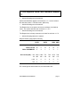
Add the following table to the manual:
Daytona Power Consumption Summary
MODEL->
24- 24-LS 12- 12-LS 8/16 4/8
POTS
POTS
UNIV UNIV
Loop Start Circuits
0
24
0
12
8
4
POTS Circuits
24
0
12
0
16
8
DSPs ASSEMBLED:
2
2
1
1
2
1
775
765
1375
780
180
130
90
235
115
DC Current (mA): +5V 1360 1350
-5V 285
+12V
0
0
0
0
0
0
-12V
0
0
0
0
0
0
DC current figures show maximums, accurate within 20%.
DOCUMENTATION ERRATA
page 6
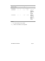
7. InLine Voice Card User’s Guide, 1.2
The table in “DSP Capabilities”, section 7 should read as shown
below.
MODEL/DSP/
[V]
[A]
[B#]
[C]
[I]
SE/1/32K/2ch
Y
Y
2
Y
Y
MEMORY/#CHANNELS
[F]
[P]
OPTIONS
-/-
-
20
NOTES
t/r
SE/1/32K/2ch
Y
Y
4
Y
Y
-/-
-
40
SE/1/32K/4ch
Y
Y
2
Y
Y
-/-
-
20
SE/1/32K/4ch
Y
Y
4
Y
Y
-/-
-
40
SE/1/32K/8ch
Y
-
2
Y
Y
-/-
-
2020
SE/1/32K/8ch
Y
Y
2
Y
-
-/-
-
420
SE/1/32K/12ch
Y
-
1
Y
Y
-/-
-
10
GT/1/128K/2ch
Y
Y
2
Y
Y
2/2
-
24
GT/1/128K/2ch
Y
Y
2
-
Y
-/-
2
202
GT/1/128K/4ch
Y
Y
2
Y
Y
-/-
-
20
GT/1/128K/4ch
Y
Y
8
Y
Y
-/-
-
80
GT/1/128K/4ch
Y
Y
4
Y
Y
4/-
-
44
GT/1/128K/4ch
Y
Y
2
Y
Y
4/2
-
1004
GT/1/128K/4ch
Y
Y
2
-
-
4/-
4
2626
GT/1/128K/4ch
Y
Y
2
-
Y
-/-
4
202
Any two of the four
channels can
receive faxes
simultaneously.
GT/1/128K/4ch
Y
Y
4
-
Y
-/-
4
242
GT/1/128K/8ch
Y
Y
2
Y
Y
-/-
-
20
GT/1/128K/8ch
Y
Y
4
Y
Y
-/-
-
40
GT/1/128K/8ch
Y
-
1
-
Y
2/2
-
1214
Only channels 0
and 1 have fax
capabilities.
GT/1/128K/8ch
Y
-
1
Y
Y
6/-
-
14
Channels 0 to 5
have fax
transmission
capabilities.
GT/1/128K/8ch
Y
-
2
Y
-
6/-
-
2424
Channels 0 to 5
have fax
transmission
DOCUMENTATION ERRATA
page 7
MODEL/DSP/
[V]
[A]
[B#]
[C]
[I]
MEMORY/#CHANNELS
[F]
[P]
OPTIONS
NOTES
t/r
capabilities.
GT/1/128K/12ch
Y
Y
2
Y
Y
-/-
-
20
GT/1/128K/12ch
Y
-
1
Y
Y
6/-
-
14
Channels 0 to 5
have fax
transmission
capabilities.
GT/1/128K/12ch
Y
Y
2
-
Y
6/-
-
224
Channels 0 to 5
have fax
transmission
capabilities.
GT/1/128K/12ch
Y
Y
2
Y
-
6/-
-
424
Channels 0 to 5
have fax
transmission
capabilities.
GT/1/128K/12ch
Y
-
1
-
Y
1/1
-
1214
Channel 0 has fax
capabilities.
GT/1/128K/12ch
Y
-
1
Y
Y
1/1
-
1014
Channel 0 has fax
capabilities.
DOCUMENTATION ERRATA
page 8
8. V-12 Voice Card User’s Guide, 4.4
The table in “DSP Capabilities”, section 7 should read as shown
below.
MODEL/DSP/
[V]
[A]
[B#]
[C]
[I]
[F]
[P]
OPTIONS
NOTES
V-12/VE1/32K/12ch
Y
-
1
Y
Y
-/-
-
10
This configuration is
discontinued.
V-12/VE1/64K/12ch
Y
Y
2
Y
V-12/VE1/64K/12ch
Y
Y
2
-
Y
-/-
-
20
Y
2/-
-
224
Channels 0 and 1
have fax
transmission
capabilities.
V-12/VE1/64K/12ch
Y
Y
2
Y
-
2/-
-
424
Channels 0 and 1
have fax
transmission
capabilities.
V-12/VE1/64K/12ch
Y
-
1
Y
Y
6/-
-
14
Channels 0 to 5
have fax
transmission
capabilities.
V-12/VE1/64K/12ch
Y
-
1
Y
Y
1/1
-
1014
Channel 0 has fax
transmission and
reception
capabilities.
V-12/VE1/64K/12ch
Y
-
1
-
Y
1/1
-
1214
Channel 0 has fax
transmission and
reception
capabilities. This
card configuration
offers more DSP
real-time capacity.
V-12/VE2/64K/12ch
Y
Y
2
Y
Y
-/-
-
20
V-12/VE2/64K/12ch
Y
Y
4
Y
Y
-/-
-
40
V-12/VE2/64K/12ch
Y
Y
2
Y
Y
12/-
-
24
V-12/VE2/64K/12ch
Y
Y
2
Y
Y
2+2/
-
1024
MEMORY/#CHANNELS
t/r
2+2
DOCUMENTATION ERRATA
Four fax channels
have transmit and
receive capabilities
but only two
channels are
available in the 0 to
5 channel number
range and two
channels in the 6 to
page 9
MODEL/DSP/
[V]
[A]
[B#]
[C]
[I]
MEMORY/#CHANNELS
[F]
[P]
OPTIONS
NOTES
t/r
11 range.
V-12/VE2/64K/12ch
Y
Y
2
-
Y
-/-
12
222
V-12/VE2/64K/12ch
Y
Y
2
-
Y
6/-
6
226
Channels 0 to 5
have pulse
capabilities and
channels 6 to 11
have fax
transmission
capabilities.
V-12/VE2/64K/12ch
Y
Y
2
-
Y
2/2
6
1226
Channels 0 to 5
have pulse
capabilities and
channels 6 to 11
have fax
transmission and
reception
capabilities.
Legend:
1. “V-12” model indicates all card variants.
2. (-) = feature not available in this configuration.
DOCUMENTATION ERRATA
page 10
9. Premiere Voice Card User’s Guide, 1.1
The table in “DSP Capabilities”, section 7 should read as shown
below.
MODEL/DSP/
[V]
[A]
[B#]
[C]
[I]
[F]
[P]
OPTIONS
NOTES
Premiere/*/32K/6ch
Y
Y
2
-
Y
-/-
6
202
This configuration is
for pulse. The
number of pulse
channels is per
DSP.
Premiere/*/64K/12ch
Y
Y
2
Y
Y
-/-
-
20
This configuration is
for advanced voice.
Premiere/*/64K/15ch
Y
-
1
Y
Y
-/-
-
10
This configuration is
for basic voice.
Premiere/*/64K/6ch
Y
Y
2
Y
Y
6/-
-
24
This configuration is
for facsimile. The
number of fax
channels is per
DSP.
Premiere/*/64K/6ch
Y
Y
2
Y
Y
2/2
-
1004
This configuration is
for facsimile. Any
two channels from 6
per DSP can be
enabled for fax.
MEMORY/#CHANNELS
t/r
Legend:
1. “Premiere” model indicates all card variants.
2. (-) = feature not available in this configuration.
3. “*” = any number of DSPs from 1 to 8. The value of channels in
the table reflects the number of channels per DSP.
4. By default, the PIKA installation program enables 12 channels per
DSP. To obtain the number of channels shown in the table, you
must modify the associated configuration file(s) that define the
number of channels enabled (e.g., DOS is PIKA.CFG).
DOCUMENTATION ERRATA
page 11
10. Daytona Voice Card User’s Guide, 1.1
The table in “DSP Capabilities”, section 7 should read as shown
below.
MODEL/DSP/
[V]
[A]
[B#]
[C]
[I]
[F]
[P]
OPTIONS
Daytona/1/64K/12ch
Y
Y
2
Y
Y
-/-
-
20
Daytona/1/64K/12ch
Y
Y
2
-
Y
2/-
-
224
Channels 0 and 1
have fax
transmission
capabilities.
Daytona/1/64K/12ch
Y
Y
2
Y
-
2/-
-
424
Channels 0 and 1
have fax
transmission
capabilities.
Daytona/1/64K/12ch
Y
-
1
Y
Y
6/-
-
14
Channels 0 to 5
have fax
transmission
capabilities.
Daytona/1/64K/12ch
Y
-
1
Y
Y
1/1
-
1014
Channel 0 has fax
transmission and
reception
capabilities.
Daytona/1/64K/12ch
Y
-
1
-
Y
1/1
-
1214
Channel 0 has fax
transmission and
reception
capabilities. This
card configuration
offers more DSP
real-time capacity.
Daytona/2/64K/24ch
Y
Y
2
Y
Y
-/-
-
20
Daytona/2/64K/24ch
Y
Y
2
-
Y
2/-
-
224
Channels 0 and 1
have fax
transmission
capabilities.
Daytona/2/64K/24ch
Y
Y
2
Y
-
2/-
-
424
Channels 0 and 1
have fax
transmission
capabilities.
Daytona/2/64K/24ch
Y
-
1
Y
Y
6/-
-
14
Channels 0 to 5
have fax
transmission
capabilities.
Daytona/2/64K/24ch
Y
-
1
Y
Y
1/1
-
1014
Channel 0 has fax
transmission and
MEMORY/#CHANNELS
NOTES
t/r
DOCUMENTATION ERRATA
page 12
MODEL/DSP/
[V]
[A]
[B#]
[C]
[I]
MEMORY/#CHANNELS
[F]
[P]
OPTIONS
NOTES
t/r
reception
capabilities.
Daytona/2/64K/24ch
Y
-
1
-
Y
1/1
-
1214
Daytona/2/64K/12ch
Y
Y
2
Y
Y
-/-
-
20
Daytona/2/64K/12ch
Y
Y
4
Y
Y
-/-
-
40
Daytona/2/64K/12ch
Y
Y
2
Y
Y
12/-
-
24
Daytona/2/64K/12ch
Y
Y
2
Y
Y
2+2/
-
1024
2+2
Channel 0 has fax
transmission and
reception
capabilities. This
card configuration
offers more DSP
real-time capacity.
Four fax channels
have transmit and
receive capabilities
but only two
channels are
available in the 0 to
5 channel number
range and two
channels in the 6 to
11 range.
Daytona/2/64K/12ch
Y
Y
2
-
Y
-/-
12
202
Daytona/2/64K/12ch
Y
Y
2
-
Y
6/-
6
206
Channels 0 to 5
have pulse
capabilities and
channels 6 to 11
have fax
transmission
capabilities.
Daytona/2/64K/12ch
Y
Y
2
-
Y
2/2
6
1206
Channels 0 to 5
have pulse
capabilities and
channels 6 to 11
have fax
transmission and
reception
capabilities.
Legend:
1. “Daytona” model indicates all card variants with the number of
channels indicated.
2. (-) = feature not available in this configuration.
DOCUMENTATION ERRATA
page 13
11. PIKA InLine DOS Reference Manual, 1.7
•
Re-order the text in Section 1, “Introduction,” first paragraph, first
sentence to read:
This manual contains information specific to the PIKA InLine DOS
driver: contents of the distribution diskette; installation; configuration;
loading and removing the driver; trace capability; and information you
might need to develop DOS applications.
•
Add the following text after “\UTILITY\CPL directory” description in
Section 2.1, “File List.”
\UTILITY\ATD directory
README.TXT
Text file that describes how to use the custom
tone detection utility.
ATDDES.EXE
The ATD package design program.
ATDPAR00.DAT
The standard call progress tone package.
ATDPAR01.DAT
The standard Belgian Dial tone package.
ATDPAR02.DAT
The standard SIT tone package.
ATDPAR03.DAT
The standard Modem calling tone (2100 Hz)
package.
ATDPAR04.DAT
The standard Modem / FAX answer tone
package.
ATDPAR05.DAT
The standard FAX CNG calling tone package.
ATDPAR06.DAT
The standard MF (R1) detector package.
TESTDES.EXE
The ATD package test program.
CONFOS.LOD, ATD.LOD
These two files are used by TESTDES.EXE to
initialize the DSP.
INIT.CMD
Used by TESTDES.EXE to initialize the InLine
hardware.
I4INIT.BIN
Used by TESTDES.EXE to initialize the InLine
hardware.
•
Revise the filenames in the “\SAMPLES\CALL directory”
description in Section 2.1, “File List” to read as shown.
DOCUMENTATION ERRATA
page 14
\SAMPLES\CALL
I4CALL.EXE
I4CALL.C
I4CALL.PRJ
•
Add the following file to “\API\INCLUDE directory” list of Section
2.1, “File List.”
CONF_RM.H
•
High-level, resource management and conference
function prototypes and data structure definitions.
Add the following file to “\API\SOURCE directory” list of Section
2.1, “File List.”
CONF_RM.C
•
Test application for outbound call.
The source code for the outbound call
application.
A Turbo C project file to build the outbound call
application.
C language interface to PIKA TSR for high-level,
resource management and conference services.
Change the font for “U” to “U” in the -Bnn option of Section 3.2,
“Initialization.”
DOCUMENTATION ERRATA
page 15
12. PIKA V-12 DOS Reference Manual, 4.2
•
Re-order the text in Section 1, “Introduction,” first paragraph, first
sentence to read:
This manual contains information specific to the PIKA V-12 DOS
driver: contents of the distribution diskette; installation; configuration;
loading and removing the driver; trace capability; and information you
might need to develop DOS applications.
•
Move the V12LOG.EXE file from the “\UTILITY\CPL directory” list
of Section 2.1, “File List” and create a new list after \UTILITY\CPL
as shown in the following text.
UTILITY\LOGGING directory
V12LOG.EXE V-12 trace analysis utility.
•
Add the following file to “SAMPLES\VOX directory” list of Section
2.1, “File List.”
VOX.C
•
Add the following file to “\API\INCLUDE directory” list of Section
2.1, “File List.”
CONF_RM.H
•
High-level, resource management and conference
function prototypes and data structure definitions.
Add the following file to “\API\SOURCE directory” list of Section
2.1, “File List.”
CONF_RM.C
•
The source code for the DC trigger voice recording
application.
C language interface to PIKA TSR for high-level,
resource management and conference services.
Add the following option switch to Section 3.1, “TSR.”
0x0002 By default, the driver no longer issues
loop current events during play, record and get
DTMF operations. For any application developed
prior to the change that relies on getting loop
current events during these operations, start the
TSR with this option switch enabled..
DOCUMENTATION ERRATA
page 16
•
Change the font for “U” to “U” in the -Bnn option of Section 3.2,
“Initialization.”
•
Add the following text within the “-o” option description of Section
3.2, “Initialization.”
0x4000 initialize a card having a VE/2 and 128K RAM
configuration with pulse detection capabilities on the second
DSP.
DOCUMENTATION ERRATA
page 17
13. PIKA Premiere DOS Reference Manual, 1.2
•
Re-order the text in Section 1, “Introduction,” first paragraph, first
sentence to read:
This manual contains information specific to the PIKA Premiere DOS
driver: contents of the distribution diskette; installation; configuration;
loading and removing the driver; trace capability; and information you
might need to develop DOS applications.
•
Rename the “UTILITY\CFAU directory” list of Section 2.1, “File
List” and binary as shown in the following text.
UTILITY\PCFAU directory
PCFAU.EXE
Premiere customer feature authorization utility.
•
Delete the following file from “API\INCLUDE directory” list of
Section 2.1, “File List.”
PIKAIF.H
•
Add the following files to “API\INCLUDE directory” list of Section
2.1, “File List.”
STRUTILS.H
FAXAPI.H
PIKACONF.H
•
FAXAPI.C
/p
Function prototypes for the event and error code
utilities.
Facsimile function prototypes and data structure
definitions.
Low-level conference function prototypes and data
structure definitions.
Add the following files to “API\SOURCE directory” list of Section
2.1, “File List.”
PIKACONF.C
•
Function prototypes and structures definition.
C interface to the TSR for low-level conference
services.
C interface to the TSR for facsimile services.
Add the following text to Section 2.2, “Configuration.”
Generate a configuration file specifically tailored for the
Premiere PTX card. (A Premiere PTX card supports only
DOCUMENTATION ERRATA
page 18
DTMF and pulse detection. A factory-configured EEPROM is
necessary for a Premiere PTX.)
•
Replace the description for -Mnn in Section 3.1, “TSR” with the
following text.
-Mnn
Specifies initial memory allocation. By default, PIKATSR
initially takes up approximately 145K of conventional
memory, approximately 48K of which is required for
internal data structures. Use this optional parameter to
allocate more or less initial memory when loading
PIKATSR. If you have more than two DSPs on the card,
the driver requires an additional 18K (approximately) for
each additional DSP. If the trace option is enabled, the
driver requires 8K (approximately) more. After PIKAINIT
is loaded, the driver frees up any unused memory. nn is
in K bytes. For example, to load the driver for a
Premiere/96, you need 156K (approximately) as shown in
the following calculation:
8 DSPs - 2DSPs = 6DSPs
6DSPs x 18K = 108K more memory than needed for a
Premiere/24.
Total for Premiere/96 = 108K + 48K = 156K
TIP #1: Load PIKATSR and PIKAINIT first, then load
other board drivers. Doing so minimizes driver memory
usage and leaving more room for other drivers to load.
TIP #2: If you want to save some initial memory on a
Premiere/24, the minimum setting available is -m48. This
value minimizes the amount of memory needed to run the
TSR without any other options.
•
Change the font for “U” to “U” in the -Bnn option of Section 3.2,
“Initialization.”
•
Add the following text to the end of Section 3.2, “Initialization.”
To initialize a Premiere PTX card, use the following options to enable
DTMF and pulse detection only:
PIKAINIT -o:4002
•
Change the section number for “Removing Premiere Driver” from
3 to 4.
DOCUMENTATION ERRATA
page 19
•
Change the section number for “Driver Trace Utility” from 4 to 5.
•
Add the following new section to the manual.
6. USING THE PREMIERE PTX
The Premiere is connected in series with a Central Office (CO) card
and an Interactive Voice Response (IVR) card. To complete this
connection, an application must call pika_connect_resource() twice.
The following example shows the parameters needed to compete
these connections.
ret = pika_connect_resource(detectorN, str_CO,
timeslot_CO, SM_FULL_DUPLEX);
ret = pika_connect_resource(detectorN,
str_IVR, timeslot_IVR,
SM_FULL_DUPLEX|SM_PULSE_IVR);
To enable DTMF and pulse detection, use the following mask shown
in the following example for pika_set_channel().
ret = pika_set_channel( ch,
PULSE_DET_ENABLED|DIGIT_IND, x);
DOCUMENTATION ERRATA
page 20
14. PIKA Daytona DOS Reference Manual, 1.1
•
Re-order the text in Section 1, “Introduction,” first paragraph, first
sentence to read:
This manual contains information specific to the PIKA Daytona DOS
driver: contents of the distribution diskette; installation; configuration;
loading and removing the driver; trace capability; and information you
might need to develop DOS applications.
•
Change the name of the data file from “V24INIT.BIN” to “V24.BIN”
in the “Root directory” list of Section 2.1, “File List.”
•
Change the name of the data file from “V24INIT.BIN” to
“V12INIT.BIN” in the “UTILITY\ATD directory” list of Section 2.1,
“File List.”
•
Change the name of the data file from “V24.BPF” to “V12.BPF” in
the “UTILITY\VOX-CONV directory” list of Section 2.1, “File List.”
•
Change the name of the feature authorization facility from
“CFAU.EXE” to “DCFAU.EXE” in the “UTILITY\CFAU directory”
list of Section 2.1, “File List.”
•
Change the font for “U” to “U” in the -Bnn option of Section 3.2,
“Initialization.”
DOCUMENTATION ERRATA
page 21
15. PIKA InLine Windows NT and Windows 95
Reference Manual, 2.0
•
Through out Section 2.1, “File List” the Visual C++ version
changes from 2.2 to 4.0.
•
Though out Section 2.1, “File List” the Visual C++ project file with
.mdp extension is included for all sample applications.
•
In the “\Bin” list of Section 2.1, “File List” change the file name and
text for the Microsoft Visual C++ DLL to read as follows.
msvcrt40.dll
Microsoft Visual C++ 4.0 DLL. This DLL must be in
the current directory or in the PATH when you start
I4DRV.EXE.
•
Move the “greeting.vox” file entry in the “\Samples\Call” list of
Section 2.1, “File List” to the “\Samples\Mail” list.
•
Add the following file to the “\Samples\Dtmf” description in Section
2.1, “File List.”
v12cpl.out
•
Call progress data needed by the outbound call
application.
Add the following text after “\Samples\Dtmf” description in Section
2.1, “File List.”
DOCUMENTATION ERRATA
page 22
\Samples\Call_Id directory
call_id.exe
Test application for caller identification.
call_id.cpp
The source code for the caller identification
application.
call_id.mdp
Sample caller identification project file for Visual C++
4.0.
call_id.mak
Sample caller identification makefile for Visual C++
4.0.
\Samples\Idx_Play directory
idx_play.exe
Test application for multi-file indexed play.
idx_play.cpp
The source code for the multi-file indexed play
application.
idx_play.mdp Sample multi-file indexed play project file for Visual
C++ 4.0.
idx_play.mak Sample multi-file indexed play makefile for Visual
C++ 4.0.
digits.vap
Indexed voice (digits) data file.
mf1.vap
Indexed voice data file.
mf2.vap
Indexed voice data file.
mf3.vap
Indexed voice data file.
DOCUMENTATION ERRATA
page 23
16. PIKA V-12 Windows NT and Windows 95
Reference Manual, 2.0
•
Through out Section 2.1, “File List” the Visual C++ version
changes from 2.2 to 4.0.
•
Though out Section 2.1, “File List” the Visual C++ project file with
.mdp extension is included for all sample applications.
•
In the “\Bin” list of Section 2.1, “File List” change the file name and
text for the Microsoft Visual C++ DLL to read as follows.
msvcrt40.dll
Microsoft Visual C++ 4.0 DLL. This DLL must be in
the current directory or in the PATH when you start
V12DRV.EXE.
•
Move the “greeting.vox” file entry in the “\Samples\Call” list of
Section 2.1, “File List” to the “\Samples\Mail” list.
•
Add the following file to the “\Samples\Dtmf” description in Section
2.1, “File List.”
v12cpl.out
•
Call progress data needed by the outbound call
application.
Add the following text after “\Samples\Dtmf” description in Section
2.1, “File List.”
DOCUMENTATION ERRATA
page 24
\Samples\Call_Id directory
call_id.exe
Test application for caller identification.
call_id.cpp
The source code for the caller identification
application.
call_id.mdp
Sample caller identification project file for Visual C++
4.0.
call_id.mak
Sample caller identification makefile for Visual C++
4.0.
\Samples\Idx_Play directory
idx_play.exe
Test application for multi-file indexed play.
idx_play.cpp
The source code for the multi-file indexed play
application.
idx_play.mdp Sample multi-file indexed play project file for Visual
C++ 4.0.
idx_play.mak Sample multi-file indexed play makefile for Visual
C++ 4.0.
digits.vap
Indexed voice (digits) data file.
mf1.vap
Indexed voice data file.
mf2.vap
Indexed voice data file.
mf3.vap
Indexed voice data file.
• Add the following option switch to Section 3, “LOADING V12
DRIVER.”
0x20000
By default, the driver no longer issues loop
current events during play, record and get
DTMF operations. For any application
developed prior to the change that relies on
getting loop current events during these
operations, start the driver with this option
switch enabled.
DOCUMENTATION ERRATA
page 25
17. PIKA Premiere Windows NT and Windows
95 Reference Manual, 1.0
•
Through out Section 2.1, “File List” the Visual C++ version
changes from 2.2 to 4.0.
•
Though out Section 2.1, “File List” the Visual C++ project file with
.mdp extension is included for all sample applications.
•
In the “\Bin” list of Section 2.1, “File List” change the file name and
text for the Microsoft Visual C++ DLL to read as follows.
msvcrt40.dll
Microsoft Visual C++ 4.0 DLL. This DLL must be in
the current directory or in the PATH when you start
DGDRV.EXE.
•
Delete the confapi.h and pikaconf.h entries in the “\Api\Include”
list in Section 2.1, “File List.”
•
Add the following files to “\Api\Include” list of Section 2.1, “File
List.”
strutils.h
conf_rm.h
•
Function prototypes for the event and error code
utilities.
high-level conference and resource management
function prototypes and data structure definitions.
Add the following text after “\Samples\Dtmf” description in Section
2.1, “File List.”
\Samples\Load directory
load.exe
Test application to play and record messages on
channels.
load.cpp
The source code for the play-and-record-message
application.
load.mdp
Sample play-and-record-message project file for
Visual C++ 4.0.
load.mak
Sample play-and-record-message make file for Visual
C++ 4.0.
play.vox
Recorded voice file for use with sample play-andrecord-message application.
DOCUMENTATION ERRATA
page 26
18. PIKA Daytona Windows NT and Windows
95 Reference Manual, 1.0
•
Through out Section 2.1, “File List” the Visual C++ version
changes from 2.2 to 4.0.
•
Though out Section 2.1, “File List” the Visual C++ project file with
.mdp extension is included for all sample applications.
•
In the “\Bin” list of Section 2.1, “File List” change the file name and
text for the Microsoft Visual C++ DLL to read as follows.
msvcrt40.dll
Microsoft Visual C++ 4.0 DLL. This DLL must be in
the current directory or in the PATH when you start
V24DRV.EXE.
•
Change the name of the data file from “v24init.bin” to “v24.bin” in
the “Root directory” list of Section 2.1, “File List.”
•
Change the name of the data file from “v24cpl.out” to “v12cpl.out”
in the “\Samples\Call” list of Section 2.1, “File List.”
•
Move the “greeting.vox” file entry in the “\Samples\Call” list of
Section 2.1, “File List” to the “\Samples\Mail” list.
•
Add the following text after “\Samples\Dtmf” description in Section
2.1, “File List.”
DOCUMENTATION ERRATA
page 27
\Samples\Call_Id directory
call_id.exe
Test application for caller identification.
call_id.cpp
The source code for the caller identification
application.
call_id.mdp
Sample caller identification project file for Visual C++
4.0.
call_id.mak
Sample caller identification makefile for Visual C++
4.0.
\Samples\Idx_Play directory
idx_play.exe
Test application for multi-file indexed play.
idx_play.cpp
The source code for the multi-file indexed play
application.
idx_play.mdp Sample multi-file indexed play project file for Visual
C++ 4.0.
idx_play.mak Sample multi-file indexed play makefile for Visual
C++ 4.0.
digits.vap
Indexed voice (digits) data file.
mf1.vap
Indexed voice data file.
mf2.vap
Indexed voice data file.
mf3.vap
Indexed voice data file.
•
Add the following text to the end of Section 2.2, “Configuration.”
You have to change V24.CFG in the following situations:
If you have a multi-card configuration and you are using MVIP
connections: you must set as MVIP master (a card that provides
the clock for the MVIP bus) the first card in the file, and as slaves
the next cards. (By default, V24INST sets all cards in master
mode).
If your application uses low-level connection functions
(pika_connect), you must remove the comments and change the
MVIP jumper configuration (V24_STR0 Dso0 ,...,). See PIKA
Daytona Voice Card Hardware Manual for more information.
If you have a card with POTS lines, you must change the circuit
type V24_CKTxx from LsGs to POTS.
You may also uncomment and change the instructions for the
allocation of the memory needed in conference: MAX_GROUPS,
MAX_TOTAL_LOCAL_CONFERENCES,MAX_TOTAL_CONFEREES.
DOCUMENTATION ERRATA
page 28
The driver allocates by default 48, 92 and 192 data structures for
groups, local conferences and conferees.
DOCUMENTATION ERRATA
page 29
19. PIKA V-12 and InLine-4 Cards Windows
DLL Reference Manual, 2.X
There are no known changes for this manual.
DOCUMENTATION ERRATA
page 30
20. PIKA V-12 and InLine-4 PIKA Custom
Control Manual, 1.0
•
The name of this manual is to change to PIKA InLine and V-12
Visual Basic VBX Manual and may appear as a reference to this
name in other manuals or PIKA documentation.
DOCUMENTATION ERRATA
page 31
21. PIKA Library Reference Manual, 4.5
•
Add “bullets” to the product support table for the following
services.
pika_AddChannel: Daytona
pika_Apply: Daytona
pika_CreateGroup (low-level conference): Daytona
pika_DeleteGroup (low-level conference): Daytona
pika_caller_id: Premiere
pika_copy_caller_id_buffer: Daytona
pika_deregister: Premiere, Daytona
pika_disable_caller_id: Premiere, Daytona
pika_enable_caller_id: Premiere, Daytona
pika_get_caller_id: Premiere
pika_get_vendor_id: InLine GT
pika_open_msg_queue: Premiere, Daytona
pika_register: Premiere, Daytona
pika_release: Premiere, Daytona
pika_seize: Premiere, Daytona
pika_seize_any: Premiere, Daytona
pika_set_output: InLine GT, Daytona
•
Delete “bullets” from the product support table for the following
services.
pika_play_beep: V-12 Classic, V-12 Formula
•
pika_set_ch (page 53): Add the following mask to the ch_mask
list.
MARK_PULSE_DIGIT (0x00010000L)
DOCUMENTATION ERRATA
page 32
Identify pulse digits with a unique
mark to distinguish them from
DTMF digits.
•
pika_record (page 104): Change the name of the referenced
function in the PIKA_CLOSE_FILE flag paragraph from
pika_mf_index_flag to pika_mf_index_play.
•
pika_select_playrec (page 112): Add the suffix _ADPCM to the
ADPCM-related flags for the rate argument (e.g., REC_RATE_32K
à REC_RATE_32K_ADPCM).
•
pika_select_playrec (page 112): Add the following flag for the
rate argument.
REC_RATE_24K_ADPCM (0x0004)
6K samples/sec, 4-bit ADPCM
==> 24Kbits/sec (DOS only).
This flag corresponds to
Dialogic’s 6K sample rate.
•
pika_add_dsp_process_to_group (page 145): Delete the
“TAppHandle hApp” parameter from the DOS syntax.
•
pika_connect (page 152): Change the <pikaapi.h> reference in
the Syntax for Windows NT and 95 to <pikaconf.h>.
•
To the “Low Level DSP Conference Services” add the following
manual pages.
pika_RemoveChannel
Remove a conference channel from a DSP conference group.
InLine
SE
Syntax
DOS
OS/2
InLine
GT
V-12
Classic
•
V-12
Formula
•
Premiere
Daytona
•
Not applicable
#include
<confapi.h>
int pika_RemoveChannel(TappHandle hApp, int board,
int groupId, int channel);
DOCUMENTATION ERRATA
page 33
NT '95
#include
<confapi.h>
int pika_RemoveChannel(TAppHandle hApp, int board,
int groupId, int channel);
Win 3.1
Not applicable
VBX
Not applicable
Description
This function removes a conference channel from a DSP conference
group.
Note:
Applications must call pika_Apply for this change to take
effect.
Arguments
hApp
board
groupId
channel
Return
Application handle.
Board number.
Group number.
Channel to remove.
PIKA_SUCCESS
PIKA_BAD_GROUP
See also
pika_Apply, pika_CreateGroup, pika_DeleteGroup,
pika_AddChannel.
•
Substitute the “Index” of Section 5 with the following pages:
DOCUMENTATION ERRATA
page 34
5. INDEX
B
byte, 1
C
capabilities_parms, 182
ch_mask, 50
Channel numbers, 1
circuit0, 154
clock, 176
clock_parms, 176
connect_desc, 154
connect_type, 155
D
dial_string, 79
Dialtone_Setup_Param, 37
dsp_msg_struct, 135
dump_parms, 178
E
EVT_CATERM, 217
EVT_DOSERR, 217
EVT_HWERROR, 218
EVT_STOP, 217
EVT_TERMDT, 217
EVT_TONE_OFF, 218
EVT_TONE_ON, 218
EVT_TONE_TMO, 218
EVT_VOX_START, 217
EVT_VOX_STOP, 217
L
license_app, 143
M
minmax, 56
mode, 204
mvip_or_line, 154
O
output_parms, 187
P
per_cadence_data, 56
pika_add_dsp_process_to_gro
up, 145
pika_add_line_to_group, 147
pika_add_mvip_to_group, 149
pika_AddChannel, 190
pika_AddMember, 197
pika_Apply, 192
pika_call, 63
pika_call_analysis, 65
pika_caller_id, 67
pika_CallResults, 122
pika_ch_stop, 74
pika_ChEvents, 124
pika_clr_dtmf, 76
pika_Commit, 200
pika_config_clock, 175
pika_connect, 152
pika_connect_resource, 204
pika_copy_caller_id_buffer, 73
pika_copy_dtmf_buffer, 77
pika_CPL, 57
pika_create_group, 156
pika_CreateGroup, 193, 195
pika_delete_group, 158
pika_DeleteGroup, 194, 196
pika_deregister, 4
pika_dial, 79
pika_dialtone_setup, 36
pika_dis_tones_detection, 81
pika_disable_caller_id, 72
pika_disconnect_resource,
206
pika_DLL_path, 120
pika_dump_switch, 177
pika_en_tones_detection, 83
pika_enable_caller_id, 70
pika_end_monitor, 39
pika_errors, 1
pika_events, 1
DOCUMENTATION ERRATA
page 35
pika_get_app_licenses, 143
pika_get_call_results, 121
pika_get_ch_capab, 139
pika_get_dtmf, 85
pika_get_dtmf_string, 87
pika_get_next_event, 124
pika_get_status, 126
pika_get_user_data, 142
pika_get_vendor_id, 138
pika_get_version, 129
pika_GetAvailRes, 203
pika_Getdts, 88
pika_group, 157
pika_index_play, 93
pika_IndexRcrdPlay, 94
pika_init, 5
pika_mf_index_play, 96
pika_MfIndex, 97
pika_MfIndexRcrdPlay, 97
pika_mvip_conf, 150
pika_open_msg_queue, 10
pika_play, 100
pika_play_beep, 116
pika_play_named_file, 102
pika_query_output, 179
pika_query_switch_caps, 181
pika_queue_event, 132
pika_RcrdPlay, 105
pika_record, 104
pika_record_named_file, 110
pika_register, 12
pika_RegParms, 14
pika_release, 40
pika_remove, 15
pika_remove_dsp_process_fro
m_grp, 160
pika_remove_line_from_group
, 162
pika_remove_mvip_from_grou
p, 164
pika_RemoveMember, 199
pika_reset_switch, 183
DOCUMENTATION ERRATA
pika_sample_input, 184
pika_scheduler, 134
pika_seize, 41
pika_seize_any, 42
pika_select_playrec, 112
pika_send_dsp_msg, 135
pika_send_hc11_msg, 137
pika_set_agc_params, 43
pika_set_ch, 49
pika_set_channel_gain, 53
pika_set_cpl, 55
pika_set_dial, 16
pika_set_energy_params, 46
pika_set_hksw_detect, 18
pika_set_hooksw, 91
pika_set_loop_current, 21
pika_set_loop_signalling, 23
pika_set_misc, 26
pika_set_option, 131
pika_set_output, 186
pika_set_ring_detect, 29
pika_set_ring_pattern, 31
pika_set_sys, 6
pika_set_tone_group_tmo, 60
pika_set_tone_pattern, 33
pika_SetGainLevel, 201
pika_start_group, 166
pika_start_monitor, 62
pika_start_ringing, 168
pika_start_tone, 170
pika_Status, 127
pika_stop_ringing, 172
pika_stop_tone, 174
pika_sys_agc, 44
pika_sys_channel_gain, 53
pika_sys_dial, 16
pika_sys_energy, 47
pika_sys_hksw_detect, 19
pika_sys_loop_current, 22
pika_sys_loop_signalling, 24
pika_sys_misc, 26
pika_sys_ring_detect, 30
page 36
pika_System, 7
pika_trace, 35
pika_tristate_switch, 188
pika_vclose, 117
pika_vcreate, 118
pika_VER, 130
pika_vopen, 119
pika_WVER, 129
R
rate, 113
Ring_Pattern, 32
Ring_Patterns, 32
S
sample_parms, 184
sec8k, 176
DOCUMENTATION ERRATA
speed, 113
status, 127
subtask, 127
T
talk_listen, 145
TChannelMap, 140
Tone_Pattern, 34
Tone_Patterns, 34
tristate, 188
TSR Access, 3
type0, 154
W
word, 1
page 37
22. Call Progress Tone Detection Facility, 2.0
There are no known changes for this manual.
DOCUMENTATION ERRATA
page 38
23. PIKA Fax API Reference Manual, 2.1
There are no known changes for this manual.
DOCUMENTATION ERRATA
page 39
24. PIKA CAS User’s Guide and Reference
Manual, 1.1
•
The following additional text applies to Section 2.1.3, “Loading
PIKA CAS Driver”:
PIKA CAS has the following memory requirements:
•
Memory is needed to load the font data (two fonts: normal and
compressed). The actual size of memory required depends upon
how many characters are used for each font. With characters
from 0x32 to 0x7F (normal ASCII), the required memory is 13,824
bytes.
•
Memory is needed by the data structures defined in the driver.
sizeof(TChanDescr)*PCDB.NumberOfFaxChanels =
2*NumberOfFaxChanels
sizeof(FPChanelQueue) = 4
sizeof(TChanelQueue) * PikaChanels = 93*PikaChanels
sizeof(TQUEUE)*PCDB.MaxQueueEvents =
27*MaxQueueEvents
sizeof(FPQUEUE)*PCDB.NumberOfFaxChanels =
4*NumberOfFaxChanels
sizeof(INT16)*PCDB.NumberOfFaxChanels =
2*NumberOfFaxChanels
sizeof(WORD)*PCDB.NumberOfFaxChanels =
2*NumberOfFaxChanels
sizeof(FPQUEUE)*PCDB.NumberOfFaxChanels =
4*NumberOfFaxChanels
sizeof(int)*PCDB.NumberOfFaxChanels =
4*NumberOfFaxChanels
CF_PROCESS_STACK_SIZE = 8192
sizeof(TFont)*2 = 22*2
NOTES:
DOCUMENTATION ERRATA
page 40
1. NumberOfFaxChanels is defined by the number of
occurrences of the parameter string FAXChanelDescr in the
PIKA CAS configuration file.
2. MaxQueueEvents is defined from the parameter string
MaxQueueEvents in the configuration file.
3. PikaChanels is the value returned by the call to pika_init().
DOCUMENTATION ERRATA
page 41
25. MVIP and PIKA Switching API User’s
Guide, 1.2
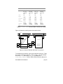
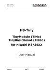
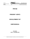
•
Figure 4 in section 2,1 “InLine GT” should be as shown in the
diagram below.
MVIP Bus
DSo
DSi
Inputs
Analog
Lines
Voice
Processing
Resources
Voice
Processing
Resources
(on VE card)
DSo7
i15
DSi7
i7
Outputs
InLine GT
MVIP
Switch
Block
o7
DSi7
o15
DSo7
i16 (0..1 on two-line cards; 0..3 on four-line cards)
o16
i17 (0..1 on two-line cards; 0..3 on four-line cards)
o17
i18 (0..15)
o18 (0..15)
Figure 4: Pseudo MVIP Switch Block Model for InLine GT Card
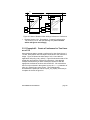
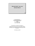
•
Figure 5 in section 2.2 “V-12” should be as shown in the diagram
below.
DOCUMENTATION ERRATA
page 42
MVIP Bus
DSo
DSi
Inputs
Analog
Lines
Voice
Processing
Resources
Conference
Resources
DSo0
DSo1
i0
i1
DSi0
DSi1
i8
i9
Outputs
V-12
MVIP
Switch
Block
o0
o1
DSi0
DSi1
o8
o9
DSo0
DSo1
i16 (0..11)
o16 (0..11)
i17 (0..11)
o17 (0..11)
i18 (0..15) Note: 18 licenses are enabled;
however, only 16 conferees are
permitted by the device driver.
o18 (0..15)
Figure 5: Factory Default MVIP Switch Block Model for V-12 Card
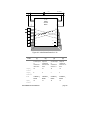
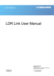
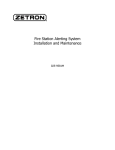
•
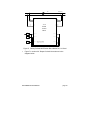
Figure 7 in section 2.4 “Daytona” should be as shown in the
diagram below.
DOCUMENTATION ERRATA
page 43
MVIP Bus
DSo
DSi
Inputs
Line
Interfaces
Conference
Resources
Voice
Processing
Resources
DSo0
DSo1
DSo2
DSo3
DSo4
DSo5
DSo6
DSo7
i0
i1
i2
i3
i4
i5
i6
i7
DSi0
DSi1
DSi2
DSi3
DSi4
DSi5
DSi6
DSi7
i8
i9
i10
i11
i12
i13
i14
i15
Outputs
Daytona
MVIP
Switch
Block
o0
o1
o2
o3
o4
o5
o6
o7
DSi0
DSi1
DSi2
DSi3
DSi4
DSi5
DSi6
DSi7
o8
o9
o10
o11
o12
o13
o14
o15
DSo0
DSo1
DSo2
DSo3
DSo4
DSo5
DSo6
DSo7
i16 (0 .. 11 on 12-line cards; 0..23 on 24-line cards)
o16
i17 (0 .. 15)
o17
i18 (0 .. 11 on 12-line cards; 0 .. 23 on 24-line cards)
o18
Figure 7: Pseudo MVIP Switch Block Model for Daytona Card
•
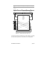
Add the following example to section 3.
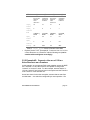
3.1.4 Example #4: Connect and Disconnect
Resources Between Two V-12s Using a Conference
Over MVIP
Assume that we have a two-card system of V-12s and we want to
connect two analog lines together through a DSP conference.
Furthermore, we use MVIP to connect the two lines to the conference
on the second board the conference is on the first board, the two
lines are on the second board. This example demonstrates how to
use pika_connect() to put the analog lines onto the MVIP bus and
PIKA conference services to complete the connection.
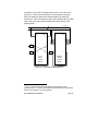
Figure 23 shows the initial switch state of the two boards applicable to
this example. The following table shows the four connect_desc
parameter values for this example.
DOCUMENTATION ERRATA
page 44
DSo
MVIP
DSi
8,0
8,1
0,0
0,1
2,0*
2,1*
V-12 Switch Block
0,0*
0,1*
V-12 Switch Block
cfee. 0
line 12
voice 12
line 13
voice 13
cfee. 1
* stream numbers do NOT
conform to the MVIP switch
block model but, rather, to
another model used by the
PIKA conference services.
Figure 23: Initial State of Switches
DOCUMENTATION ERRATA
page 45
Field
Card #2
Card #2
Card #2
Card #2
ACTION:
(1) connect
line 12 to
the MVIP
bus
(2) connect
the MVIP
bus to line
12
(3) connect
line 13 to
the MVIP
bus
(4) connect
the MVIP
bus to line
13
card
n/a
n/a
n/a
n/a
type0
LINE
LINE
LINE
LINE
circuit0
{ 12 }
{ 12 }
{ 12 }
{ 12 }
type1
MVIP
MVIP
MVIP
MVIP
circuit1
{ 0, 0 }
{ 8,0 }
{ 0,1 }
{ 8,1 }
connect_
TALK0 |
LISTEN1
TALK1 |
LISTEN0
TALK0 |
LISTEN1
TALK1 |
LISTEN0
type
Table 6: connect_desc Values to Make Connections to MVIP
Figure 24 shows the resulting state of the switch blocks.
DSo
MVIP
DSi
0,0
0,1
8,0
8,1
2,0*
2,1*
1
V-12 Switch Block
2
4
0,0*
0,1*
V-12 Switch Block
3
cfee. 0
line 12
voice 12
line 13
voice 13
cfee. 1
* stream numbers do NOT
conform to the MVIP switch
block model but, rather, to
another model used by the
PIKA conference services.
Figure 24: State of Switches After MVIP Connections
To complete the connection, we use the conference services. Firstly,
we create a conference with pika_create_group(). For this example,
we set the flags field of the pika_group parameter to
PIKA_START_IMPLED. Refer to PIKA Library Reference Manual for
DOCUMENTATION ERRATA
page 46
more details of pika_create_group(). Secondly, we now add the
conferees to the conference. To do so, we use
pika_add_mvip_to_group(). This function takes a similar set of
parameters as pika_connect(). However, as noted in the figure
above, the convention for numbering MVIP streams is not the same
as the convention used by pika_connect(). Rather, MVIP stream
numbers correspond to the relative sequence of the MVIP stream
identifiers in the board’s configuration file. Table 7 shows an example
segment of a V-12 configuration file and the associated stream
number assignment used by pika_add_mvip_to_group().
V12.CFG Field
Stream Number
V12_STR0 DSo0
0
V12_STR1 DSo1
1
V12_STR2 DSi0
2
V12_STR3 DSi1
3
Table 7: Example Stream Number Assignment for
pika_add_mvip_to_group()
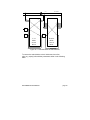
To complete the conference, we make two calls to
pika_add_mvip_to_group() as shown in Table 8. Figure 25 shows the
completed conference.
Field
ACTION:
Card #1
Card #1
(1) add the first
conferee to the
conference (line 12)
(2) add the second
conferee to the
conference (line 13)
fTALK | fLISTEN
fTALK | fLISTEN
inp_mvip_stream
2
2
inp_mvip_timeslot
0
1
inp_gain
0
0
out_mvip_stream
0
0
out_mvip_timeslot
0
1
out_gain
0
0
access
Table 8: pika_mvip_conf Values to Complete Conference
DOCUMENTATION ERRATA
page 47
DSo
MVIP
DSi
8,0
8,1
0,0
0,1
2,0*
2,1*
1
V-12 Switch Block
0,0*
0,1*
V-12 Switch Block
1
cfee. 0
2
line 12
line 13
voice 12
voice 13
cfee. 1
Conference 0
2
* stream numbers do NOT
conform to the MVIP switch
block model but, rather, to
another model used by the
PIKA conference services.
Figure 25: State of Switches After Adding Conferees to Conference
•
Replace Section 3.2.1, “Example #1: Create a Conference for
Two Lines on a V-12” with the following text (and re-number
tables and figures accordingly).
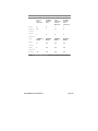
3.2.1 Example #1: Create a Conference for Two Lines
on a V-12
Assume that we want to create a conference for lines 0 and 4 on a V12 card. Both parties need full-duplex connections to the conference
bridge. Figure 23 shows the initial state of a V-12 card after an
application calls pika_reset_switch(). Figure 24 shows the state of the
switch after we make the conference connections. Note that this
example assumes that you have created the conference with the
appropriate conference functions in the PIKA API. We assume that
there is only one board in the system; hence, the board parameter of
pika_set_output() has a value of zero. The following table
summarizes the parameter values to pika_set_output() necessary to
complete the circuits of figure 24.
DOCUMENTATION ERRATA
page 48
MVIP Bus
DSo
DSi
Inputs
DSo0
DSo1
i0
i1
DSi0
DSi1
i8
i9
Outputs
V-12
MVIP
Switch
Block
o0
o1
DSi0
DSi1
o8
o9
DSo0
DSo1
Analog
Line
0
i16 (0)
o16 (0)
Analog
Line
4
i16 (4)
o16 (4)
Voice
Resource
0
i17 (0)
o17 (0)
Voice
Resource
4
i17 (4)
o17 (4)
Conference
Resource
6
i18 (6)
silence
o18 (6)
Conference
Resource
7
i18 (7)
silence
o18 (7)
Figure 23: Initial Switch State for V-12
Field
(1)
(2)
(3)
(4)
ACTION:
Connect line
0 to the input
of
conference
resource 6
Connect the
output of
conference
resource 6 to
line 0
Connect line
4 to the input
of
conference
resource 7
Connect the
output of
conference
resource 7 to
line 4
output_
18
16
18
16
6
0
7
4
mode
CONNECT_
MODE
CONNECT_
MODE
CONNECT_
MODE
CONNECT_
MODE
input_
16
18
16
18
stream
output_
timeslot
stream
DOCUMENTATION ERRATA
page 49
Field
(1)
input_
(2)
(3)
(4)
0
6
4
7
n/a
n/a
n/a
n/a
timeslot
message
Table 7: output_parms Values to Make Connections
MVIP Bus
DSo
DSi
Inputs
DSo0
DSo1
i0
i1
DSi0
DSi1
i8
i9
V-12
MVIP
Switch
Block
Outputs
o0
o1
DSi0
DSi1
o8
o9
DSo0
DSo1
Analog
Line
0
i16 (0)
o16 (0)
Analog
Line
4
i16 (4)
o16 (4)
Voice
Resource
0
i17 (0)
o17 (0)
Voice
Resource
4
i17 (4)
o17 (4)
Conference
Resource
6
i18 (6)
o18 (6)
Conference
Resource
7
i18 (7)
o18 (7)
Figure 24: Two-party Conference with V-12
To restore the switch to its initial state, you must call pika_set_output()
four times with the parameter values shown in the following table.
DOCUMENTATION ERRATA
page 50
Field
(1)
(2)
(3)
(4)
ACTION:
Reconnect
line 0 to the
output of
voice
resource 0
Reconnect
conference
resource 6
to silence
Reconnect
line 4 to the
output of
voice
resource 4
Reconnect
conference
resource 7
to silence
output_
16
18
16
18
0
6
4
7
mode
CONNECT_
MODE
PATTERN_
MODE
CONNECT_
MODE
PATTERN_
MODE
input_
17
n/a
17
n/a
0
n/a
4
n/a
n/a
0xFF
n/a
0xFF
stream
output_
timeslot
stream
input_
timeslot
message
Table 8: output_parms Values to Restore Initial State
•
Replace Section 3.2.2, “Example #2: Connect a Line on a V-12 to
a Voice Resource on a Premiere” with the following text (and renumber tables and figures accordingly).
3.2.2 Example #2: Connect a Line on a V-12 to a
Voice Resource on a Premiere
In this example, we connect two PIKA cards together across the MVIP
bus. Both the V-12 and the Premiere are capable of being either
“network” or “resource” cards. For this example, assume that the V12 is the “network” card as board zero in the system and the Premiere
is the “resource” card as board one.
As we have done for the other examples, assume that we start from
an initial state the switch as configured by a reset operation. We
DOCUMENTATION ERRATA
page 51
use stream 1, time-slot 5 to bridge the two cards. Line 3 and voice
resource 171 are the two end-points for our full-duplex connection.
Figure 25 shows the states of the switches before we make any
connections. Figure 26 shows the state of the switches after we make
calls to pika_set_output() with the parameter values shown in the
following table.
MVIP Bus
DSo
DSi
Inputs
DSo0
DSo1
Outputs
i0
i1 (5)
o0
o1 (5)
Inputs
DSi0
DSi1
DSi2
DSi3
DSi4
DSi5
DSi6
DSi7
Analog
Line
3
i16 (3)
o16 (3)
Voice
Resource
3
i17 (3)
o17 (3)
V-12
MVIP
Switch
Block
Outputs
DSi0
DSi1
Voice
Resource
17
i8
i9 (5)
i10
i11
i12
i13
i14
i15
o8
o9 (5)
o10
o11
o12
o13
o14
o15
i17 (5)
o17 (5)
DSo0
DSo1
DSo2
DSo3
DSo4
DSo5
DSo6
DSo7
Premiere
MVIP
Switch
Block
Figure 25: Initial State of Switch Blocks
1
The V-12 is the first card in the system and provides voice
resources 0 to 11. Hence, the sixth voice resource on the Premeiere
card is voice resource 17 in the system.
DOCUMENTATION ERRATA
page 52
Field
(1)
(2)
(3)
ACTION:
Connect line
3 to the
MVIP bus
Connect the
MVIP bus to
line 3
Board
0
0
1
1
output_
16
1
17
9
3
5
5
5
mode
CONNECT_
MODE
CONNECT_
MODE
CONNECT_
MODE
CONNECT_
MODE
input_
1
16
9
17
5
3
5
5
n/a
n/a
n/a
n/a
Connect
voice
resource 17
to the MVIP
bus
(4)
Connect the
MVIP bus to
voice
resource 17
stream
output_
timeslot
stream
input_
timeslot
message
Table 9: output_parms Values to Make Connections
DOCUMENTATION ERRATA
page 53
MVIP Bus
DSo
DSi
Inputs
DSo0
DSo1
Outputs
i0
i1 (5)
o0
o1 (5)
(2)
Analog
Line
3
i16 (3)
Inputs
Outputs
DSi0
DSi1
DSi0
DSi1
DSi2
DSi3
DSi4
DSi5
DSi6
DSi7
(1)
i8
i9 (5)
i10
i11
i12
i13
i14
i15
o8
o9 (5)
o10
o11
o12
o13
o14
o15
o16 (3)
(4)
Voice
Resource
3
DSo0
DSo1
DSo2
DSo3
DSo4
DSo5
DSo6
DSo7
i17 (3)
o17 (3)
V-12
MVIP
Switch
Block
Voice
Resource
17
(3)
i17 (5)
o17 (5)
Premiere
MVIP
Switch
Block
Figure 26: Connected State of Switch Blocks
To restore the switch blocks to their initial state, issue four
pika_set_output() calls with the parameters shown in the following
table.
DOCUMENTATION ERRATA
page 54
Field
(1)
(2)
(3)
(4)
Disconnect
the MVIP
bus from
line 3
Disconnect
voice
resource 17
from the
MVIP bus
Disconnect
the MVIP
bus from
voice
resource 17
ACTION:
Reconnect
line 3 to
voice
resource 3
Board
0
0
1
1
output_
16
1
17
9
3
5
5
5
mode
CONNECT_
MODE
DISABLE_
MODE
DISABLE_
MODE
DISABLE_
MODE
input_
17
n/a
n/a
n/a
3
n/a
n/a
n/a
n/a
n/a
n/a
n/a
stream
output_
timeslot
stream
input_
timeslot
message
Table 10: output_parms Values to Restore Initial State
DOCUMENTATION ERRATA
page 55
26. PIKA Trans-4M/Inline-4M MITEL
Integration Peripheral Cards for PC
Compatibles Hardware Manual, 1.03
There are no known changes for this manual.
DOCUMENTATION ERRATA
page 56
27. PIKA Trans-4M MITEL Integration Software
Development Toolkit for PC Compatibles, 1.31
There are no known changes for this manual.
DOCUMENTATION ERRATA
page 57
28. PIKA dsPTX User Manual, 1.09
There are no known changes for this manual.
DOCUMENTATION ERRATA
page 58