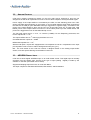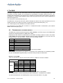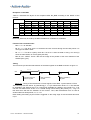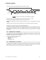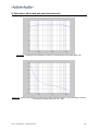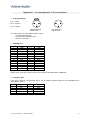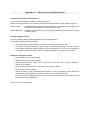
1
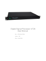
Digital Signal Processor UT26
User Manual
Ref : UT26-UM_0709A
Author : XM
Date : Juillet 2009
CONTENTS
1 Introduction ......................................................................................3
1.1
1.2
1.3
1.4
Presentation.................................................................................................. 3
Applications .................................................................................................. 4
Master and Slave Processors...................................................................... 4
Programming - DADE - JTAG ...................................................................... 4
2 Installation........................................................................................5
2.1
2.2
2.3
2.4
2.5
Installing the UT26........................................................................................ 5
Connecting Several UT26 ............................................................................ 5
Setting the address (IDENT) ........................................................................ 6
Fail Safe Mode............................................................................................... 7
Connection to a PC....................................................................................... 7
3 Audio Inputs and Outputs ...............................................................8
3.1
3.2
3.3
Analog Inputs................................................................................................ 8
Analog Outputs............................................................................................. 9
AES/EBU Digital Input .................................................................................. 9
4 The BAN.......................................................................................... 10
4.1
4.2
4.3
Transmission of the audio signals............................................................ 10
Transmission of commands ...................................................................... 12
Transmission of clock H48 ........................................................................ 12
5 The computer port ......................................................................... 13
6 The BCL port .................................................................................. 14
7 Programming with DADE............................................................... 15
7.1
7.2
7.3
Introduction................................................................................................. 15
Programming the Codec ............................................................................ 15
Using the flash memory ............................................................................. 15
8 Frequency response and background noise ............................... 16
Appendix 1 : Bloc diagram ................................................................. 18
Appendix 2 : pin assignment of the connectors.................................2
Appendix 3 : Timing of codec interrupts.............................................3
Appendix 4 : Options and daughter boards ........................................1
UT26 – User Manual – UM-UT26-0709A
2
1 INTRODUCTION
Analog
Inputs
§ 3.1
Analog
Outputs
§ 3.2
Digital input
AES/EBU
§ 3.3
BAN
§4
BCL
§6
RS232
§ 2.5 et 5
Mains
§ 2.1
Figure 1.1 : Rear panel
1.1 PRESENTATION
The UT26 is a multi-channel digital signal processor, in a 19" / 1U rack format. It is equipped with
the CTB26 board, which features a Motorola DSP 56L307VF160. Several UT26 racks can be
connected so that they can exchange audio signals and commands through the BAN848 low
latency network, thus creating a multiprocessor system (BAN see § 4).
A device equipped with a serial port (e.g. a PC) can control a whole group of UT26 racks.
The bloc diagram of the UT26 is presented in appendix 1, showing namely :
-
the input and output buffers,
-
the CTB26 board with its : DSP, codec, BAN manager, flash memory,
-
several ports : BAN848, BCL, Computer,
-
a number of internal connectors, designed to host daughter boards so as to integrate specific
functions.
The latter point is one of the main characteristics of the UT26. These connectors and daughter
boards give the UT26 its versatility and a large capacity for evolution, opening up greatly the field of
possible applications. The development of specific daughter boards is presented in appendix 4.
The front panel of the UT26 doesn’t have any control (except for the On/Off switch). Control of the
operating parameters can be done :
-
via a PC running an appropriate software, such as DADE (see www.activeaudio.fr) and
connected either to the command channel of the BAN, or to the RS232 port (see § 4.2),
-
via a remote control connected to one of the control ports of the UT26, and communicating with
the DSP via a daughter board (see Appendix 4)
-
by placing controls on the front panel, which is removable (contact us).
Note that the UCT26 processor includes a User Interface consisting of a 2x20 chrs display and a
set of buttons for navigation in a menu tree.
The UT26 rack is shipped with the DADE development software environment, which manages all
the hardware resources of the CTB26 board (DSP, codec, flash memory, BAN…) and makes easy
the development and implementation of plugins providing functions needed by the user (see § 7).
UT26 – User Manual – UM-UT26-0709A
3
1.2 APPLICATIONS
The UT26 processor is dedicated to the digital processing of audio signals :
-
Control of an array of loudspeakers (EQ, directivity,…)
-
Multi-effects treatment (delay, compressor, limiter, reverb, convolution…)
-
Active control, thanks to the low latency of signal transfer through the BAN.
The flexibility given by the possibility of linking several UT26 processors, of adding daughter boards
on inputs, outputs, and the BAN848, BCL and Computer ports, considerably broadens the field of
applications (see appendix 4).
1.3 MASTER AND SLAVE PROCESSORS
When several UT26 processors are connected on the same BAN network, one of them should be
the master processor which generates the 48 kHz clock (H48) used to sample all the processors,
so that they are all synchronized. There should be only one master processor connected to the
BAN848.
The master processor is equipped with a DSP board CTB26-M, and the slave processors are
equipped with a CTB26-E board. These boards are equipped with a set of 4 micro-switches which
should be configured to set the BAN address of each processor (see § 2.3 et 2.4).
There should never be two master processors on the same BAN.
There should never be two processors with the same address on the BAN.
If there is only one UT26 processor, this processor should have a CTB26-M DSP board.
1.4 PROGRAMMING - DADE - JTAG
DADE (Digital Audio Development Environment) is dedicated to DSP software development and
implementation on the CTB26 board. It manages all the resources of the CTB26 board (DSP,
codec, flash memory, BAN, serial port…), thus making it extremely easy for the user to develop his
own algorithms and specific functions as plug-ins (see § 7).
DSP programming is performed via the command channel of the BAN (BANcmd), from the serial
port of a PC for example, without using a JTAG emulator.
However, it is also possible to program the DSP via the JTAG port (on the CTB26 board) using a
JTAG emulator, so that traditional debugging tools such as breakpoints may be used (see
appendix 1 of the DADE User Manual). This also means that the low levels need to be
programmed (drivers codec, BAN, flash, SCI port). The JTAG port being very fragile, our
guarantee doesn’t apply once the JTAG port has been used to program the processor.
UT26 – User Manual – UM-UT26-0709A
4
2 INSTALLATION
The UT26 processor is designed to be housed in a 19" / 1U rack format.
2.1 INSTALLING THE UT26
The mains should be connected to 230v – 50Hz.
In the mains plug there is are two 5x20mm fuses, type 100mA / 250v slow.
The power switch on the front panel is lit (green) when the power is on.
CAUTION : this equipment should not be in contact with water, even dripping or spatter. No
container with liquid such as vases should be placed on the equipment.
CAUTION : this equipment should be connected to a supply base socket having an earth
connection for protection.
2.2 CONNECTING SEVERAL UT26
Several UT26 processors can be connected in daisy chain network with the BAN848 connector
(SubD25 male). If the link is short (up to 1 m approximately, depending on the electromagnetic
environment), a simple 25-conductor wire ribbon cable with SubD25 male connectors can be used.
For longer links (up to 100 m), a 12-pair twisted cable should be used (see pin description of the
BAN in appendix 2), and termination resistors (120Ω on A23) as well as polarization resistors
(1000Ω on A21 and A22) should be placed on the processors at both end of the daisy chain
network (see figure 3.1).
A21
A23
A22
Figure 3.1 : Sockets for polarization and termination resistances on the main board of the UT26
processor.
UT26 – User Manual – UM-UT26-0709A
5
2.3 SETTING THE ADDRESS (IDENT)
The address of a processor on the BAN is called IDENT. It is set with the micro-switches on the
CTB26 board.
The CTB26-M board (master) should always have IDENT 0
The CTB26-E boards (slave) have IDENT addresses from 1 to 7.
There should never be two processors with the same IDENT on the same BAN. There should be
one and only one master processors on a BAN.
Remember the CTB26-M board (IDENT 0) has 2 emitting channels on the BAN, and the CTB26-E
boards (IDENT 1 to 6) have only one emitting channel. The board with IDENT 7 cannot emit a
signal on the BAN.
CAUTION : UT26 Processors are shipped with address set to 0 for master processors, and
address 1, 2, … for slave processors (see § 1.3). If the user needs to change the address, this may
be done by the dealer or by the user himself provided he take usual caution to protect components
against electromagnetic discharges. Guarantee does not cover possible damages.
Figure 3.2 shows the positions of the micro-switches on the CTB26 board.
Position “1” of the micro-switches corresponds to the edge of the board. The micro-switch located
towards the corner of the board corresponding to the LSB (Least Significant Bit).
Table 3.2 and figure 3.2 illustrate the setting of the IDENT switches.
With oscillator : master board
th
4 microswitch
IDENT = 0
Without oscillator : slave board
th
4 microswitch
IDENT = 1
Figure 3.2 : Configuring the IDENT. Left : master board ; Right : slave board
IDENT
Table 3.2 : Configuring the IDENT micro-switches.
(bottom corresponds to the edge of the board)
µswitches
0
1
2
3
4
5
6
7
The IDENT is read when the DSP reads a data on the BAN (see § 4.1).
NB : The IDENT determines the attribution of the channels on the BAN (see § 4). In DADE, it is
also the address of the processor on BANcmd. There cannot be more than 8 processors on the
BAN (IDENT = 0 to 7). However, it is possible to interface more than 8 processors on BANcmd if
the BANcmd address is set another way. For example, the address may be written and then read
in the flash memory.
UT26 – User Manual – UM-UT26-0709A
6
2.4
FAIL SAFE MODE
th
The state of the 4 micro-switch is affected to bit 21 of the data read by the DSP on the BAN. It has
no effect on the assignment of the audio channels of the BAN (see § 4.1), and can therefore be
used freely by the user.
In DADE, it is used to select the Fail Safe Mode. If the micro-switch is ON (towards the edge of the
board), DADE does not load the user plug-in from the flash memory during booting (power up).
This is useful in case the user plug-in has a bug which corrupts the dialog on BANcmd, and the
user is unable to regain control of DADE (see DADE user manual).
2.5 CONNECTION TO A PC
A computer (or any other device equipped with a serial port) may be connected to the command
channel of the BAN (see the BAN pin assignment in appendix 2) in order to control all the
installation. This BANcmd channel is an RS485 link, the length of which can be up to 100 m.
For shorter lengths (up to 25 m approximately), the PC can be connected to the RS232 port
(socket SubD 9 male) if the UT26 is equipped with the CV232 daughter board (option) which does
the conversion RS232 ↔ RS485 of the BANcmd.
UT26 – User Manual – UM-UT26-0709A
7
3 AUDIO INPUTS AND OUTPUTS
3.1
ANALOG INPUTS
UT26 has 2 analog symmetrical inputs on XLR female sockets. Appendix 2 gives the pin
assignment as well as an explanation on how to connect an asymmetrical signal.
The full scale input level of these inputs is +/- 3.25v, i.e. 2.3vrms (+9.5dBU).
However, this level is set at +/- 1.9v for the UT26's to be used with StepArray columns.
st
The input buffers have a 1 order high-pass at 6 Hz.
Crosstalk between channels is < -90dB.
Differential impedance is > 10kΩ.
Option HD (high dynamic) available on the UT26 is a pre-emphasis / de-emphasis system which
yields to 97 dB SNR (max level at 1kHz / background noise Lin 20Hz-20kHz, with DSP in pass-thru
mode) due to a significant reduction of background noise at high-frequencies. This option consists
of a circuit which pre-emphasises high frequencies on the 2 analog inputs (1 first order zero at
3000Hz, one first order pole at 10kHz) and of a complementary circuit which de-emphasises the 6
outputs. Frequency responses of the pre-emphasis and de-emphasis circuits are shown on figure
3.3.
Note : The main board of the UT26 can receive a daughter board on the analog input buffer
section, so that a specific filtering can be added. For example, a microphone preamplifier with
phantom power supply can be added, so that a microphone can then directly be connected to a
UT26 input.
Figure 3.3 : amplitude of the frequency responses (dB) of the pre-emphasis (blue) and
de-emphasis (red) circuits of the mother board CM26 - HD option.
UT26 – User Manual – UM-UT26-0709A
8
3.2
ANALOG OUTPUTS
UT26 has 6 analog symmetrical outputs on the XLR male socket. Appendix 2 gives the pin
assignment as well as an explanation on how to connect these outputs to an asymmetrical signal.
Power supply of the output buffers is controlled by the DSP, so that switching power ON / OFF
doesn’t generate large transients on the outputs. A circuit rapidly detects power down and informs
the DSP via the NMI pin (Non Maskable Interrupt, triggered on negative edge). Command of the
power of the output buffers is done via the TIO1 pin of the DSP (TIO1 set power ON). With
DADE, power of the output buffers is turned on 1 second after power-up of the CTB26 board, and
power off is triggered as soon as the NMI interrupt occurs.
The full scale output level is +/- 3.5v, i.e. 2.5vrms (+10dBU). For the StepArray processors, this
level is adjusted to +/-1.8v.
st
The output buffers have a 1 order high-pass filter at 4.5 Hz.
Crosstalk between outputs is < -90dB.
Differential impedance is < 10Ω.
With the HD option, outputs are equipped with a de-emphasis circuit as a complement to the input
pre-emphasis circuit in order to reduce background noise (see § 3.1).
NB : The main board of the UT26 can receive a daughter board on the analog output buffer
section, so that a specific filtering can be added. Contact us.
3.3
AES/EBU DIGITAL INPUT
UT26 has a stereo digital AES/EBU input on an XLR female socket. This digital input is mutually
exclusive from the analog ones. Choice of the type of input (analog / digital) is made by the
software on the DSP (see DADE user manual).
Supported sampling frequencies are 44.1kHz and 48kHz.
This input complies to standards AES3-2003, EBU 3250-E, and EN 60958-4.
UT26 – User Manual – UM-UT26-0709A
9
4 THE BAN
The BAN is a digital audio bus which allows several UT26 processors to exchange audio signals and
commands. All these signals and commands are transmitted via RS485 symétrical links 0 /+5v,
enabling safe transmission over at least 100 m. Signals are protected with transyl diodes. The BAN is
accessible on a 25-pin female SubD25 socket on the rear panel of the UT26. The pin assignment is
depicted in appendix 2.
For connection of several UT26, see § 2.2.
The BAN also conveys the H48 clock (used to sample the codecs of the slave processors) from the
master processor to the slave processors, so that they are all synchronized (see § 1.3).
A 5v / 25mA supply is also available on the BAN connector.
The assignment of the BAN audio channels to a CTB26 DSP board is determined by the address
IDENT of the board (see § 2.3).
4.1
TRANSMISSION OF THE AUDIO SIGNALS
The BAN has 8 audio channels sampled at 48kHz (BAN848). An FPGA chip on the CTB26 board
ensures the interface between the BAN and the DSP.
Assignment of the channels is determined by the IDENT according to table 4.1 below. The master
UT26 (IDENT=0) has two emitting channels, while the slave units (IDENT=1 to 6) only have one
emitting channel. UT26 with IDENT 7 doesn’t have any emitting channel.
IDENT Emission on channel(s)
0
SON1 and SON2
1
RA1
2
RA2
3
RA3
4
RA4
5
RA5
6
RA6
7
Tableau 4.1 : assignment of BAN audio channels according to IDENT.
Audio samples transmitted by the BAN are 16 bit words. If the transmission is controlled by DADE,
only the 16 MSB (Most Significant Bits) of the DSP words (24 bits) are transmitted.
Emission on the BAN
Table 4.2 describes the layout of the emission buffer TX_BAN as a function of IDENT.
Address TX_BAN
X:$20008 X:$20009
Other
0
SON1
SON2
Not valid
1
RA1
Not valid
Not valid
2
RA2
Not valid
Not valid
IDENT
3
RA3
Not valid
Not valid
4
RA4
Not valid
Not valid
5
RA5
Not valid
Not valid
6
RA6
Not valid
Not valid
Not valid
Not valid
Not valid
≥7
Table 4.2 : layout of the emission buffer as a function of the IDENT of the emitter.
The TX_BAN buffer can be accessed by the DSP at addresses X :$20008 and X :$20009.
The data transmitted are the 16 MSB (bits 8 to 23) of the words written in TX_BAN.
UT26 – User Manual – UM-UT26-0709A
10
Reception on the BAN
Table 4.3 describes the layout of the reception buffer RX_BAN according to the IDENT of the
receiver.
Address in RX_BAN
X:20000
X:20001 X:20002 X:20003 X:20004 X:20005 X:20006
Other
0
RA1
RA2
RA4
RA5
RA6
Not valid
1
RA2
RA3
RA4
RA5
RA6
SON1
SON2 Not valid
2
RA1
RA3
RA4
RA5
RA6
SON1
SON2 Not valid
IDENT
3
RA1
RA2
RA4
RA5
RA6
SON1
SON2 Not valid
4
RA1
RA2
RA3
RA5
RA6
SON1
SON2 Not valid
5
RA1
RA2
RA3
RA4
RA6
SON1
SON2 Not valid
RA1
RA2
RA3
RA4
RA5
SON1
SON2 Not valid
≥6
Table 4.3 : layout of the reception buffer RX_BAN according to the IDENT of the receiver.
Buffer RX_BAN may be read by the DSP at addresses X :$20000 to X :$20006.
Format of the received words :
-
Bits 0 - 15 : 16 data bits.
-
Bit 16 : New. This bit is set at 1 if the data has been received during the last H48 period. It is
clear (0) if the data is older.
-
Bit 17 : Err. This bit is a parity check bit. It is set at 1 when the data is wrong. It is clear (0)
when the transmission is correct (parity test OK).
-
Bits 18 à 21 : IDENT. These 4 bits are the image of the position of the micro-switches of the
l’IDENT (See § 2.3).
Timing
The H48 clock synchronizes transmission of the audio signals on the BAN as shown on figure 4.1.
20,8 µs
H48
T
The DSP writes the
data in TX_BAN
T+1
T+2
Data is emitted on
the BAN
Data is available in
RX_BAN
Figure 4.1 : Timing of the transmission of audio signals on the BAN - synchronisation of H48.
The user may write the data in TX_BAN during [T ; T+1[ for transmission at time T+1. This data will
be available in RX_BAN at time T+2. It will remain available for reading in the period [T+2 ; T+3[
until the next data arrives at time T+3. If a data writing is done during the period [T+1 ; T+2[, it is
this data which will then be available on the receiver. Thus, data transmission from a UT26 to
another takes two H48 periods, i.e. 41.7 µs.
Data reading and writing by the FPGA is triggered on the rising edge of H48 and takes less than
0.1µs
UT26 – User Manual – UM-UT26-0709A
11
The timing on figure 4.2 illustrates transmission of data D = $52A6.
H48
SON1
Idle
Data ( LSB first)
Parity bit
Start
Figure 4.2 : Example of transmission of data $52A6 on the BAN.
Duration of a frame (from rising edge of H48 and end of the parity bit) is 11.6µs.
This duration is slightly greater than half a period of H48 ( 10.42µs ).
Duration of the idle state is 0.666 µs (which corresponds to 1 bit, the transmission clock being
1.5MHz).
Appendix 3 depicts the timing of the codec relative to H48 and therefore relative to the BAN.
Transmission of several signals on one single BAN channel
It is possible to transmit several interleaved decimated signals on the same BAN channel. For
example 2 signals sampled at 24kHz, or 6 signals at 8kHz. However, this implies that all UT26
processors are synchronized on the lowest sampling frequency used. See appendix 2 of DADE
user manual.
4.2
TRANSMISSION OF COMMANDS
The command channel of the BAN (BANcmd) is a RS485 link which allows the UT26 to receive
commands from a PC (or any other device equipped with a serial port), and answer these
commands. For connection to a PC, see § 2.5.
In DADE, the transmission parameters are :
- baud rate : 38400 bits / sec
- Data bits : 8
- Stop Bits : 1
- Flow control : RTS
4.3
TRANSMISSION OF CLOCK H48
The master processor (IDENT=0) generates the 48kHz master clock (H48), which is transmitted
symmetrically on the BAN in 0 / 5v (H48+ and H48- out of phase). This clock is used by all the
codecs of the slave units, as well as the transmission of signals on the BAN.
UT26 – User Manual – UM-UT26-0709A
12
5 THE COMPUTER PORT
For connecting this port, see § 2.5.
The Computer port is an RS232 serial port which allows connection to a PC (or any other device
equipped with a serial port) via the BANcmd. The UT26 should be equipped with the CV232 option
which ensures the conversion RS232 ↔ BANcmd.
The PC controls the direction of the flow via the RTS signal :
-
RTS set : PC UT26
-
RTS clear : UT26 PC
UT26 – User Manual – UM-UT26-0709A
13
6 THE BCL PORT
The signals on the BCL port (SubD 15 female socket on rear pannel) are connected to connectors of
the main board in the UT26 (see appendix 1). Plugging optional daughter boards on these connectors
allows to implement specific functions linking the BCL port with the CTB26 board (see appendix 4).
If no daughter board is used, then there is no link between the BCL port and the CTB26 board, and
the BCL port is unused.
With an adequate daughter board, the BCL port may for example :
-
interface a remote control unit,
-
interface a sensor,
-
Provide an extra analog output.
When transmitting signals over a long distance, termination resistors (120Ω) and polarisation resistors
(1kΩ) should be placed on A24, A25, A26 (see figure 6.1).
A 9v / 50mA power supply is available on the BCL connector
Contact us for more information.
A24
A25
A26
Figure 6.1 : position of sockets for polarisation (A25) and termination (A24, A26) resistors of the BCL
on the mother board of UT26.
UT26 – User Manual – UM-UT26-0709A
14
7 PROGRAMMING WITH DADE
7.1
INTRODUCTION
DADE (Digital Audio Development Environment) is a programming environment developped by
Active Audio for users of the CTB26 board (and processors that use it, such as UT26). DADE
consists of a "shell" ran by the DSP of the CTB26 board, and a PC software which interfaces with
the DSP via its SCI port. The PC ↔ UT26 dialog is done via the BANcmd link (see § 2.5).
The DADE shell manages the main resources of the CTB26 board (codec, flash memory, SCI port,
BAN), and manages the plug-ins developed by the user. Hence the user only has to implement his
own specific code. A DADE plug-in has 4 parts :
-
Initialization, which is called at the start of the plug-in ;
-
The sample processing, which is called at every sampling period ;
-
The response to user commands, which is called every time a user command is received on
the SCI port ;
-
The background tasks, which are called in an endless loop when the above tasks are
completed.
DADE is shipped with a library of plug-in examples which illustrates the most frequent functions :
bi-quadratic cells, convolution with the EFCOP co-processor, LMS filtering, FFT, decimation /
interpolation, management of timers and host port …
See DADE User Manual for more information.
7.2
PROGRAMMING THE CODEC
The CS4226 codec has 2 analog symmetrical inputs, an S/PDIF input (connected to the AES/EBU
input of the UT26) and 6 analog asymmetrical outputs. Programming of the codec is explained in
detail in the user manual of the CS4226 “cs4226-f2.pdf” which can be downloaded on the web site
of the manufacturer (Crystal Semiconductors). Programming is straightforward using routines
rdspi and wrspi accessible by the plug-ins. A programming example is given in plug-in Xover2.
7.3
USING THE FLASH MEMORY
The flash memory ST M29W010B of the CTB26 board is a 1 Mbit memory divided into 8 sections
of 16384 bytes. All details about this chip can be downloaded from the web site of the manufacturer
(Etmel). Reading is performed per byte, but writing can only be made on a whole sector. Hence, for
modifying one or several data of the same sector, one should first copy the whole sector into RAM,
modify it in RAM, and finally copy the buffer into the flash memory. This can easily be done by a
plug-in using the adequate routines of the DADE shell. These routines can handle reading / writing
24 bits words (3 bytes) from / to flash. See ShellEqu.asm.
Note : The manufacturer guarantees 100 000 writing operation per sector of the flash memory.
UT26 – User Manual – UM-UT26-0709A
15
8 FREQUENCY RESPONSE AND BACKGROUND NOISE
Figure 8.1 : Amplitude of the frequency response of l’UT26 in pass-thru mode (dB vs Hz)
Figure 8.2 : Phase of the frequency response of UT26 in pass-thru mode. A 2.377 ms delay has been
introduced so that the phase is 0° at 1 kHz.
UT26 – User Manual – UM-UT26-0709A
16
Figure 8.3 : Typical background noise measures in third octave (dBmV vs Hz) for the 6 output
channels of the UT26. DSP in pass-thru mode. Analog inputs not connected.
Wide band 20Hz-20kHz values per channel :
Out 1 : -22.8 dBmV
Out 2 : -23.1 dBmV
Out 3 : -23.1 dBmV
Out 4 : -22.6 dBmV
Out 5 : -23.1 dBmV
Out 6 : -22.7 dBmV
Mean dynamic range : 90.2dB
UT26 – User Manual – UM-UT26-0709A
17
Appendix 1 : Bloc diagram
(see next page)
UT26 – User Manual – UM-UT26-0709A
18
Signals I/O
Bloc diagram
of processor
UT26
CTB26 Board
Buffer
AES/EBU stereo
(XLR-F)
UT26
"IN"
Analog input 1
(XLR-F)
Flash
memory
Limiter
Buffer
JP15
JP13
JTAG
Daughter board
CTRL
"IN"
Limiter
Analog input 2
(XLR-F)
Buffer
JP16
JP14
HIO8
"OUT"
Output 1
(XLR-M)
Buffer
DSP
JP17
JP2
JP18
Codec
"OUT"
Output 2
(XLR-M)
Buffer
3
JP1
JP19
JP20
+5v
BCL
"OUT"
Buffer
Output 3
(XLR-M)
+5v
+5v
+5v
µswitchs
JP22
Buffer
J7B
JP23
BAN
management
JP24
"OUT"
Output 5
(XLR-M)
2
12
Transceiver
"OUT"
Output 4
(XLR-M)
2
BAL
+5v
J7A
JP21
BSL
Buffer
Transceiver
J4
J3
JP25
JP26
J2
"OUT"
Output 6
(XLR-M)
Buffer
JP27
JP28
JP30
+9v
JP30
Connector 2.54mm step
"IN"
Daughter board Inputs
"OUT"
Daughter board Outputs
"CTRL"
Daughter board Control
-9v
3
JP31
+9v
-9v
+8v
+5v
1p
JP8
JP9
-8v
+5v
H48
signals
2 wires
HIO8 : 8 bit parallel I / O port. See Motorola doc
JP2 : Event port, comprising TIO2, MODA, MOBD, MODC, MODD, RESET, +3,3v
JP1 : 3 lines connected to the Host port (PB8, PB9, PB10) via buffers
JTAG : see Motorola doc
I/O
Control
and BAN
5
1p
+9v
2
1p
BANcmd
BAN848
Connector : SubD25 F socket
2p : 2 pairs
8
C/R
JP29
1 power supply +5v
1 clock H48
1 command channel BANcmd
IDENT 0 :
2 signal emission channels
6 signal reception channels
IDENT 1-6 :
1 signal emission channel
7 signal reception channels
Computer
Connector :
SubD9 F socket
Pin assign : RS232
If JP8 and JP9
shorted, BANcmd
on pins 1 and 6
BCL
Connector :
SubD15 F socket
1 power supply +9v
4 pairs to internal
connectors
2 pairs to transceivers
Appendix 2 : pin assignment of the connectors
♦
Analog XLR plug
Pin 1 : GND
2
Pin 2 : Signal +
1
3
1
2
3
Pin 3 : Signal XLR female plug
exterior view
XLR male plug
exterior view
For connecting to an asymmetrical input / output :
- Connect Signal to pin 2
- Connect ground (GND) to pin 1
- Short pin 1 and pin 3.
♦
BAN848 port
Pin #
1
2
3
4
5
6
7
8
9
10
11
12
13
Signal
GND
C/RH48SON1SON2RA1RA2RA3RA4RA5RA6GND
+5v
Pin #
14
15
16
17
18
19
20
21
22
23
24
25
Signal
GND
C/R+
H48+
SON1+
SON2+
RA1+
RA2+
RA3+
RA4+
RA5+
RA6+
GND
Signals C/R+ and C/R- are the 2 lines for the symmetrical transmission of BANcmd.
♦
Computer port
If the port is used to communicate with a PC via RS232 (CV232 option), the pin assignment for
connection to a PC is
Pin #
1
2
3
4
5
Signal
C/R+ via JP8
RX
TX
NC
GNDNUM
Pin #
6
7
8
9
UT26 – User Manual – UM-UT26-0508A
Signal
C/R- via JP9
RTS
NC
NC
2
Appendix 3 : Timing of codec interrupts
Case of the master CTB26 board (IDENT 0) :
20.8 µs
H48
Codec
Tx_ls_isr
Rx_ls_isr
0.5 µS
0.35 µS
20.8 µs
H48
Codec
Tx_isr
Rx_isr
Rx_isr
Tx_isr
0.5 µS
0.7 µS
Case of the slave CTB26 boards (IDENT 1 to 7)
20.8 µs
H48
Codec
Tx_ls_isr
0.6 µS
Rx_ls_isr
0.4 µS
20.8 µs
H48
Codec
Tx_isr
Rx_isr
0.5 µS
0.5 µS
UT26 – User Manual – UM-UT26-0508A
Tx_isr
Rx_isr
0.4 µS
0.4 µS
3
Appendix 4 : Options and daughter boards
Daughter boards and standard options
Active Audio offers daughter boards and standard options :
Option HD (High Dynamic) : Pre-emphasis of the inputs and de-emphasis of the outputs (see § 3.1)
Option CV232 :
Daughter board for RS232 / RS485 conversion, so that the Computer RS232 port
is interfaced with the DSP via the BANcmd (see § 2.5.)
Option PM1UT26 : Daughter board consisting of a microphone preamplifier with 14v phantom supply
on analog input 2.
Specific Daughter boards
It is also possible to develop daughter boards for a specific application.
Two modes of development are possible :
-
Active Audio does the development according to the specifications of the client.
-
The user does the development himself, after a partnership agreement has been signed.
Active Audio provides all details necessary for the development. In this case, the guarantee is
not applicable since Active Audio cannot be held responsible for any damage to the UT26.
Examples of daughter boards :
-
Specific filtering on the analog inputs.
-
Specific filtering on the analog outputs.
-
Assigning interrupt lines, GPIO lines, or HIO8 lines on the BCL port in order to interface a
specific User Interface.
-
Route a serial port to the BCL in order to interface a remote control.
-
Route sensor inputs to the BCL.
-
Interface controls on the UT26 front panel. Example : UCT26 comprising an LED display and
push buttons has a daughter board which interfaces the controls with the DSP.
-
Route one or several additional outputs on the BCL connector (as with option SUB used with
StepArray column loudspeakers).
Contact us for more information.