1
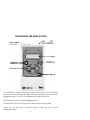
® An OMEGA Technologies Company http://www.omega.com e-mail: [email protected] OM-EL-HL HANDHELD INFRARED CONTROLLER omega.com TM ® OMEGAnet On-Line Service http://www.omega.com SM Internet e-mail [email protected] Servicing North America: USA: ISO 9001 Certified Canada: One Omega Drive, Box 4047 Stamford, CT 06907-0047 Tel: (203) 359-1660 e-mail: [email protected] 976 Bergar Laval (Quebec) H7L 5A1 Tel: (514) 856-6928 e-mail: [email protected] FAX: (203) 359-7700 FAX: (514) 856-6886 For immediate technical or application assistance: USA and Canada: Mexico and Latin America: SM Sales Service: 1-800-826-6342 / 1-800-TC-OMEGA SM Customer Service: 1-800-622-2378 / 1-800-622-BEST SM Engineering Service: 1-800-872-9436 / 1-800-USA-WHEN TELEX: 996404 EASYLINK: 62968934 CABLE: OMEGA SM Tel: (95) 800-TC-OMEGA En Español: (203) 359-1660 ext:2203 FAX: (95) 203-359-7807 e-mail: [email protected] Servicing Europe: Benelux: Czech Republic: France: Germany/Austria: United Kingdom: ISO 9002 Certified Postbus 8034, 1180 LA Amstelveen, The Netherlands Tel: (31) 20 6418405 Toll Free in Benelux: 06 0993344 e-mail: [email protected] Ostravska 767, 733 01 Karvina Tel: 42 (69) 6311899 e-mail: [email protected] 9, rue Denis Papin, 78190 Trappes Tel: (33) 130-621-400 Toll Free in France: 0800-4-06342 e-mail: [email protected] Daimlerstrasse 26, D-75392 Deckenpfronn, Germany Tel: 49 (07056) 3017 Toll Free in Germany: 0130 11 21 66 e-mail: [email protected] 25 Swannington Road, Broughton Astley, Leicestershire, LE9 6TU, England Tel: 44 (1455) 285520 FAX: 44 (1455) 283912 Toll Free in England: 0800-488-488 e-mail: [email protected] FAX: (31) 20 6434643 FAX: 42 (69) 6311114 FAX: (33) 130-699-120 FAX: 49 (07056) 8540 PO Box 7, Omega Drive, Irlam, Manchester, M44 5EX, England Tel: 44 (161) 777-6611 FAX: 44 (161) 777-6622 It is the policy of OMEGA to comply with all worldwide safety and EMC/EMI regulations that apply. OMEGA is constantly pursuing certification of its products to the European New Approach Directives. OMEGA will add the CE mark to every appropriate device upon certification. The information contained in this document is believed to be correct but OMEGA Engineering, Inc. accepts no liability for any errors it contains, and reserves the right to alter specifications without notice. WARNING: These products are not designed for use in, and should not be used for, patient connected applications. &RQWHQWV Introduction Requirements First Time User Using the EasyLog Data Logger Navigating the Menu Systems Initial Setup Attaching EasyLog to OM-EL-HL Main Menu 1. Search 2. Status 3. Start 3.1 Active 3.2 Alarms 3.3 High Alarm 3.4 Low Alarm 3.5 Start Mode 3.6 Start Logger 4. Stop 5. Download 6. Emulate 7. Setup 7.1 Logger Name 7.2 Sensor Type 7.3 Sample Rate 7.4 Storage Method 7.5 LCD Symbol 7.6 Scaler 7.7 Default Cal 7.8 Update and Exit 8. Advanced 8.1 Reset Logger 8.2 Clear Logger 8.3 New Address 9. OM-EL-HL Comms 9.1 Interface 9.2 Smart Search 9.3 Search Limit 10. Time 11. Date Quick Menu Compatible Products Specification Index Software Licence Agreement 1 2 3 3 3 4 5 5 6 6 7 7 7 7 8 8 8 8 8 9 9 10 10 10 10 10 11 11 11 11 11 12 12 12 12 12 12 13 13 13 14 15 16 17 18 200(/0+/ +DQGKHOG &RQWURO 8QLW IRU (DV\/RJ The OM-EL-HL is a low cost, hand-held EasyLog configuration and data collection unit which can be operated by both technical and non-technical personnel. The OM-EL-HL is designed to be used in environments where a Windows based PC is either unavailable or impractical. Up to eight EasyLogs can be configured and the data from each stored in non-volatile memory that will hold the data until it can be analyzed on a PC. 200(/0+/ FRQWDLQV= 4 [ +DQGKHOG &RQWURO 8QLW 5 [ $$ %DWWHULHV 4 [ 6ôµ )ORSS\ 'LVN :LWK 200(/0:,1 ) +/0+(/3 4 [ '0W\SH WR '0W\SH &RPPXQLFDWLRQV &DEOH 4 [ 200(/0+/ 0DQXDO 2 5(48,5(0(176 The OM-EL-HL is a field tool for data retrieval and configuration of the Omega EasyLog series of data loggers. The OM-EL-HL is designed to be used in conjunction with a PC running OM-EL-WIN EasyLog control software. Minimum System Requirements • IBM compatible PC running Windows 3.1 or above. • OM-EL-WIN version 3.01 or above. • One or more EasyLogs. • EasyLog RS232 serial cable. • D-type to D-type RS232 serial cable. (Included) Optional • OM-EL-LINK-IR - Self powered RS232 to InfraRed converter for the PC. • OM-EL-PANEL-IR - Panel Mounting InfraRed transmitter / Receiver. • OM-EL-2-IR - OM-EL-2 with InfraRed communications. ),567 7,0( 86(56 For users not familiar with the EasyLog range, please refer to the EasyLog datasheets and OM-EL-WIN user manual. 86,1* 7+( ($6</2* '$7$ /2**(5 A typical logging scenario consists of four stages:- 1. Selecting and connecting an appropriate sensor. 2. Choosing the desired recording method and starting the log. 3. Stopping the log after the required period and extracting the recorded data. 4. Presenting and analyzing the data. 3 1$9,*$7,1* 7+( 0(18 6<67(0 The OM-EL-HL is operated by using a simple menu system. The Up and Down arrow keys navigate the main/sub menus, while left and right arrow keys select the appropriate logger. A “beep” will confirm that a key has been pressed. The Enter key is used to select the highlighted menu. The Escape key will revert to the previous menu without saving any data. Arrow keys are also used in selected menus to allow the user to enter alpha/numeric data. 4 ,1,7,$/ 6(783 Before operating the OM-EL-HL for the first time, two 1.5V AA type batteries must be inserted correctly in the battery compartment on the rear of the unit. The cover of the battery compartment is held in place by a single screw. With the batteries in place, press the ON/OFF key to power up the OM-EL-HL. The internal microprocessor clock will now need to be set with the correct time and date. This is accomplished by using the Current Date and Current Time menus as described on page 13. The OM-EL-HL will also indicate a Low Battery Warning on power up if the batteries have a low level of charge left. If this message is displayed, the user is advised to switch off the OM-EL-HL and replace the batteries. The clock will then require re-setting. Once the clock has been set, the OM-EL-HL is ready to use. N.B. When replacing the batteries, it is advisable for the user to wait approximately 15 seconds before inserting the new batteries. This will allow the OM-EL-HL’s low power circuitry to fully discharge. $77$&+,1* $1 ($6</2* 72 200(/0+/ Using the EasyLog interface cable (from OM-EL-WIN), plug the 9-way D socket of the lead into the serial port at the top of the OM-EL-HL. The opposite end of the lead is connected to the EasyLog. Depending on the module, the connector at this end could be either a 9-way D socket, an 8-pin Mini-DIN or the jack plug supplied with OM-EL-WIN-LITE. Alternatively, the integrated InfraRed communication link can be selected in the Comms menu. The InfraRed link may be used with OM-EL-PANEL-IR, OM-ELLINK-IR or OM-EL-2-IR. OM-EL-LINK-IR can also be used for InfraRed communication with a PC. 5 0$,1 0(18 The main menu consists of the following options:41 6($5&+ 51 67$786 61 67$57 71 6723 81 '2:1/2$' 91 (08/$7( :1 6(783 ;1 $'9$1&(' <1 200(/0+/ &2006 431 &855(17 7,0( 441 &855(17 '$7( 41 6($5&+ Pressing <Enter> searches for any loggers attached to the OM-EL-HL. As the OM-EL-HL searches, loggers that reply will be shown by their relevant address number on the top row of the LCD display. A dashed line in place of the logger’s address indicates that no logger has been found at that address. On menus 2 - 7, selection of a logger is accomplished by utilising the left and right arrow keys. The flashing cursor will highlight the selected logger, with the up and down arrow keys highlighting the relevant menu. Pressing <Enter> will select the highlighted logger and menu. Selection of menus 2 - 5 will show on the top row of the display the current logger’s address number, followed by its name. The second row shows all other relevant data. If the selected EasyLog is active or in a delayed start, the user will be unable to enter the menu. The logger must be stopped before the user is able to alter any settings. 6 51 67$786 With STATUS displayed, pressing <Enter> will open the menu. By using the up and down keys, the following parameters can be examined. 41 6(1625 7<3( 51 6$03/( 5$7( 61 6725$*( 02'( 71 /&' 6<0%2/6 81 /2**(5 67$7( 91 180%(5 2) 6$03/(6 Press <Esc> to return to the main menu. 61 67$57 With START displayed, pressing <Enter> will open the menu. The following submenus can be scrolled through by using the up and down arrow keys. 1. 2. 3. 4. 5. 6. ACTIVE ALARMS HIGH ALARM LOW ALARM START MODE START LOGGER 3.1 ACTIVE ∗∗ This function controls the active symbol on the EasyLog display. Pressing <Enter> will toggle the feature on or off. When enabled, this symbol is displayed every second for the duration of the logger being active. It is useful for confirming correct operation of the logger during long sample rates as well as troubleshooting. 3.2 ALARMS ∗∗ Pressing <Enter> will toggle the ALARMS on or off. With the option set, if the EasyLog’s reading exceeds either of the limits, then this is indicated by an HI (or LO) display condition alternating with the reading on the EasyLog’s display. The alarm levels are saved with the data and are visible when data is exported to a PC running OM-EL-WIN. Additionally, hardware outputs are available for both levels on the logger, which may be used (via suitable buffer circuitry) to drive external signalling equipment. 7 3.3 HIGH ALARM Pressing <Enter> will prompt you to enter the high alarm value. This is achieved by using the up and down arrow keys to display from a decimal point to 9. The most significant digit also displays a polarity symbol. The left and right arrows are used to move along the sequence of numbers. Press <Enter> to return to sub-menu. 3.4 LOW ALARM For setting the low alarm level, the same commands as high alarm are used. ∗∗ N.B. Refer to OM-EL-WIN manual for cautions regarding timing accuracy. 3.5 START MODE Pressing <Enter> will toggle between:• NORMAL : EasyLog will start logging as soon as START LOGGER is activated. • PUSH TO START : Allows you to start the logger from the front button (OMEL-2) or by connecting a switch between header pins SW and V- on the OM-EL-1 (see datasheet). • DELAYED START TIME : Enter desired start time in a similar manner as entering alarm data but in hours/minutes/seconds. • DELAYED START DATE : Enter desired start date using the same commands as delayed start time but in day/month/year. • DELAYED START : Will utilise the EasyLog system clock and start the logger at the entered time and date described in delayed time and date start. OMNOTE: Because the current time & date will be downloaded from the EL-HL unit to the EasyLog, be sure to set the time & date correctly on the OM-ELHL first. 3.6 START LOGGER Pressing <Enter> will start the logger in its selected mode. 71 6723 With STOP displayed, pressing <Enter> will stop the logger if it is active. Once the logger has been stopped, the next set of samples taken will start from the beginning and overwrite previous data. 8 81 '2:1/2$' With DOWNLOAD displayed, pressing <Enter> will open the menu. You are then prompted to choose one of the eight memory locations in which to store the collected data from the selected EasyLog. The up and down arrow keys are used to scroll through the memory locations. The display will show the name of the last logger to download data into that memory location. If there is no data held in a memory location the display will show EMPTY. Once a memory location has been selected press <Enter> to start the DOWNLOAD routine. The OM-EL-HL will “Beep”, while data is being downloaded from the EasyLog. The memory location selected for the EasyLog to download its data will also become that EasyLog’s new address for the EMULATE mode. For example, if the EasyLog’s data has been downloaded into memory location 5, the EasyLog’s address in the EMULATE mode will also be 5. Memory locations can be cleared by the CLEAR command in OM-EL-WIN (Emulate Mode). 91 (08/$7( In this mode, the OM-EL-HL emulates an EasyLog module for the purpose of downloading the collected information to OM-EL-WIN. The PC looks upon the OM-EL-HL as between 1 and 8 EasyLogs depending on how many loggers have been downloaded to the OM-EL-HL. Connect the OM-EL-HL to your PC with the supplied 9way D-type to D-type cable or equivalent. Select the EasyLog Emulation Mode on the OM-EL-HL by pressing <Enter>. Using the OM-EL-WIN software on your PC, click on SEARCH. The OM-ELWIN software will show all the EasyLogs that have been downloaded to the OMEL-HL. Data is stored on the OM-EL-WIN software in the normal manner. 9 :1 6(783 With SETUP displayed, pressing <Enter> will open the menu. The following submenus can be scrolled through by using the up and down arrow keys. 1. 2. 3. 4. 5. 6. 7. 8. LOGGER NAME SENSOR TYPE SAMPLE RATE STORAGE METHOD LCD SYMBOL SCALER DEFAULT CAL UPDATE AND EXIT 7.1 LOGGER NAME Pressing <Enter> will prompt you to change the logger name. The name is changed by using the up and down arrow keys to display the available characters. The left and right arrows are used to move along the sequence of up to 14 characters. Press <Enter> to return to sub-menu or accept current name. 7.2 SENSOR TYPE Select SENSOR TYPE by pressing <Enter>. The available sensors for the connected logger can be scrolled through by using the up and down arrows. Press <Enter> to select the sensor or return to sub-menu. N.B. Available Sensor options are dependent on logger type. 7.3 SAMPLE RATE Select SAMPLE RATE by pressing <Enter>. The available sample rates can be scrolled through by using the up and down arrows. Press <Enter> to select the rate or return to sub-menu. 7.4 STORAGE METHOD Select STORAGE METHOD by pressing <Enter>. The following storage types can be scrolled through by using the up and down arrow keys:• NORMAL : This is the conventional method used for recording data over a period of time. Readings are taken at regular time intervals and stored as a sequence of values inside the EasyLog module. Logging stops once the module’s memory is full. The maximum number of readings that can be stored inside an EasyLog module is limited by the size of the module’s memory. • HISTOGRAM : In Histogram mode, individual readings are not stored. Instead, the occurrence of each reading is recorded. This means that many more readings can be processed over a longer period of time. NOTE: The Histogram storage method is not an option for the 12BIT EasyLogs. 10 • ROLLING : Rolling data storage is similar to Normal data storage, except that when the EasyLog module’s memory is full, logging continues by overwriting the oldest data. When logging is stopped, the module contains all the readings leading up to the time of stopping. Use Rolling mode to record data that leads up to a particular event. • EVENT : In Normal, Rolling and Histogram mode, readings are taken at regular time intervals. In Event mode, a reading is only taken and stored when the Event button is pressed. Refer to the EasyLog module’s datasheet for more information. In Event mode, each reading is stored together with the time and date of the reading. 7.5 LCD SYMBOL Select LCD SYMBOL by pressing <Enter>. The available annunciators, which are dependent on the type of EasyLog module being used, can be scrolled through by using the up and down arrows. Press <Enter> to select the desired symbol or return to sub-menu. N.B. Symbols available are dependent on logger type. 7.6 SCALER As in sub-menu 3.5 LCD SYMBOL above, but used to change the scaler annunciator. 7.7 DEFAULT CAL Press <Enter> to reset the current logger’s calibration settings to the factory default. WARNING! Only select this menu if you are sure you want to overwrite any custom values that have previously been set. 7.8 UPDATE AND EXIT Press <Enter> to update the current settings for the logger and return to the main menu. ;1 $'9$1&(' With ADVANCED displayed, pressing <Enter> will open the menu. The following sub-menus can be scrolled through by using the up and down arrow keys. 1. RESET LOGGER 2. CLEAR LOGGER 3. NEW ADDRESS 11 8.1 RESET LOGGER EasyLog is supplied from the factory pre-configured for a 5 second sampling rate in Normal storage mode and in the modules default temperature range. If you wish to return the logger to this condition press <Enter>. Remember, all readings will be lost. This option also restores the default calibration settings. DO NOT USE if the logger has been User/Custom calibrated, unless you have the means to accordingly re-calibrate sensor to logger. 8.2 CLEAR LOGGER If you wish to clear all of the old stored readings from the selected EasyLog, press <Enter>. Although all old readings are erased, the module’s configuration parameters will remain unchanged. 8.3 NEW ADDRESS Pressing <Enter> will prompt the user to change the logger’s address. Use the up and down arrow keys to scroll through any free addresses in the range 0 - 7. Press <Enter> to change the address or return to the sub-menu. N.B. The search limit (see OM-EL-HL Comms) should be set high enough to allow the new address to be shown by the OM-EL-HL. <1 200(/0+/ &2006 With OM-EL-HL COMMS displayed, pressing <Enter> will open the menu. The following sub-menus can be scrolled through by using the up and down arrow keys. Press <Esc> to return to the main menu. 1. INTERFACE 2. SMART SEARCH (S. SEARCH) 3. SEARCH LIMIT 9.1 INTERFACE Pressing <Enter> will toggle between the RS232 and the InfraRed communication interface. 9.2 SMART SEARCH Pressing <Enter> will toggle SMART SEARCH on or off. With SMART SEARCH on, the OM-EL-HL will scan twice in succession for each module address, thus increasing the chance that a given module is free to respond. 12 9.3 SEARCH LIMIT If you are confident that all the module addresses are at the lower end of the scale (e.g.: addresses 0, 1, 2, 3) then you can substantially increase the search speed by selecting the highest module address that you expect to find. Pressing <Enter> will allow you to change the SEARCH LIMIT. Use the up and down arrow keys to scroll through and select search limit between 0 - 7. Press <Enter> to change the limit or return to the sub-menu. NOTE: It is recommended initially that this option is left set at its default value of 7. 431 7,0( The current time can be changed by pressing <Enter> and then using the up and down arrow keys to alter the digits (Hrs., Min., Sec.). The left and right arrows are used to move along the sequence of numbers. Press <Enter> to set the time with this value and return to menu. 441 '$7( The current date can be changed by pressing <Enter> and then using the up and down arrow keys to alter the digits (Day, Month, Year.). The left and right arrows are used to move along the sequence of numbers. Press <Enter> to set the date stored in the OM-EL-HL and return to menu. 13 48,&. 0(18 SEARCH ⇓⇑ STATUS ⇓⇑ START ⇓⇑ STOP ⇓⇑ DOWNLOAD ⇓⇑ EMULATE ⇓⇑ SETUP ⇓⇑ ADVANCED ⇓⇑ ⇒ ⇒ ⇒ ⇒ ⇒ ⇒ Sensor Type Sample Rate Storage Mode LCD Symbol Logger State Number of Samples ⇒ ⇒ ⇒ ⇒ ⇒ ⇒ Active Alarms High Alarm Low Alarm Start Mode ⇒ normal / push to start / delayed start time / ⇒ delayed start date/delayed start Start Logger ⇒ ⇒ ⇒ ⇒ ⇒ ⇒ ⇒ ⇒ Logger Name Sensor Type ⇒ dependent on logger type Sample Rate Storage Method ⇒ normal / histogram / rolling / event LCD Symbol ⇒ dependent on logger type Scaler Default Cal Update and Exit ⇒ ⇒ ⇒ Reset Logger Clear Logger New Address OM-EL-HL COMMS ⇓⇑ ⇒ ⇒ ⇒ Interface ⇒ RS232 / InfraRed Smart Search Search Limit TIME ⇓⇑ DATE 14 &203$7,%/( 352'8&76 200(/04 200(/0/,7( 200(/04045%,7 200(/05 200(/05045%,7 200(/0/,1.0,5 2003$1(/0,5 15 200(/050,5 63(&,),&$7,21 3+<6,&$/ &+$5$&7(5,67,&6 Size 120mm x 64mm x 23mm/4.72” x 2.56” x 0.86” Weight 150g/5.3oz (incl. batteries) Screen size 36.5mm x 10mm/1.44” x 0.39” Screen type 16 characters by 2 lines Supertwist dot matrix LCD Sound Piezo buzzer Keyboard 7 key “Clicktouch” membrane 32:(5 6833/< Requirement Current consumption 0(025< Built in 2 x AA 1.5V alkaline cells Typical “On” = 45mA Typical “Stand By” = 20µA 8 full EasyLog dataloggers &20081,&$7,216 Ports RS232 & IrDA compatible InfraRed Baud rate 9600 IR TX range 1 meter (19,5210(17 Operating temp. 0°C to 50°C Storage temp. -20°C to 50°C Operating humidity 0% to 80% non condensing EMC For Europe: EN55022 Class B 16 ,QGH[ $ + 5 Active 7 Address 12, 13 Advanced 6, 11, 12 Alarms 7, 8 Annunciators 7, 10, 11 Attaching 5 High Alarm 7, 8 Histogram 10 Requirements 3 Reset 11, 12 Rolling 11 % , 6 Batteries 2, 5, 16 InfraRed 4, 5 Information 2, 18 Initial Set-up 5 Interface 12, 14, 15, 16, 18 & / Calibrate 12 Clear Logger 11, 12 Clock 5, 6, 13 Comms. 4-6, 12 Compatible Prod. 3, 15 LCD Symbol 10, 11 Licence 18 Logger Name 10 Low Alarm 7, 8 ' 0 Sample Rate 10 Scaler 10, 11 Search Limit 12, 13 Sensor 7, 10 Set-up 5, 6, 10 Search 6 Smart Search 12, 13 Specification 16 Start 6, 7, 8 Status 6, 7 Stop 6, 8 Storage 3, 7, 10, 11, 16 Set Time / Date 5, 6, 13 Symbol 10, 11 System Requirements 3 Date 5, 6, 13 Menu - Main 6 Delayed Start 8 Menu - Quick 14 Default Calibration 12 Download 6, 9 ( 1 7 Emulate 6, 9 Event 11 Name 10 Navigating 4, 6, 14 Normal 8, 10 Number of Samples 6 Time 5, 6, 13 ) 3 8 Factory Defaults 12 First Time User 3 Push-To-Start 8 Using EasyLog 3 4 Quick Menu 14 17 WARRANTY/DISCLAIMER OMEGA ENGINEERING, INC. warrants this unit to be free of defects in materials and workmanship for a period of 13 months from date of purchase. OMEGA Warranty adds an additional one (1) month grace period to the normal one (1) year product warranty to cover handling and shipping time.This ensures that OMEGA’s customers receive maximum coverage on each product. If the unit should malfunction, it must be returned to the factory for evaluation. OMEGA’s Customer Service Department will issue an Authorized Return (AR) number immediately upon phone or written request. Upon examination by OMEGA, if the unit is found to be defective it will be repaired or replaced at no charge. OMEGA’s WARRANTY does not apply to defects resulting from any action of the purchaser, including but not limited to mishandling, improper interfacing, operation outside of design limits, improper repair, or unauthorized modification. This WARRANTY is VOID if the unit shows evidence of having been tampered with or shows evidence of being damaged as a result of excessive corrosion; or current, heat, moisture or vibration; improper specification; misapplication; misuse or other operating conditions outside of OMEGA’s control. Components which wear are not warranted, including but not limited to contact points, fuses, and triacs. OMEGA is pleased to offer suggestions on the use of its various products. However, OMEGA neither assumes responsibility for any omissions or errors nor assumes liability for any damages that result from the use of its products in accordance with information provided by OMEGA, either verbal or written. OMEGA warrants only that the parts manufactured by it will be specified and free of defects. OMEGA MAKES NO OTHER WARRANTIES OR REPRESENTATIONS OF ANY KIND WHATSOEVER, EXPRESSED OR IMPLIED, EXCEPT THAT OF TITLE, AND ALL IMPLIED WARRANTIES INCLUDING ANY WARRANTY OF MERCHANTABILITY AND FITNESS FOR A PARTICULAR PURPOSE ARE HEREBY DISCLAIMED. LIMITATION OF LIABILITY: The remedies of purchaser set forth herein are exclusive and the total liability of OMEGA with respect to this order, whether based on contract, warranty, negligence, indemnification, strict liability or otherwise, shall not exceed the purchase price of the component upon which liability is based. In no event shall OMEGA be liable for consequential, incidental or special damages. CONDITIONS: Equipment sold by OMEGA is not intended to be used, nor shall it be used: (1) as a “Basic Component” under 10 CFR 21 (NRC), used in or with any nuclear installation or activity; or (2) in medical applications or used on humans. Should any Product(s) be used in or with any nuclear installation or activity, medical application, used on humans, or misused in any way, OMEGA assumes no responsibility as set forth in our basic WARRANTY/DISCLAIMER language, and additionally, purchaser will indemnify OMEGA and hold OMEGA harmless from any liability or damage whatsoever arising out of the use of the Product(s) in such a manner. RETURN REQUESTS / INQUIRIES Direct all warranty and repair requests/inquiries to the OMEGA Customer Service Department. BEFORE RETURNING ANY PRODUCT(S) TO OMEGA, PURCHASER MUST OBTAIN AN AUTHORIZED RETURN (AR) NUMBER FROM OMEGA’S CUSTOMER SERVICE DEPARTMENT (IN ORDER TO AVOID PROCESSING DELAYS). The assigned AR number should then be marked on the outside of the return package and on any correspondence. The purchaser is responsible for shipping charges, freight, insurance and proper packaging to prevent breakage in transit. FOR WARRANTY RETURNS, please have the following information available BEFORE contacting OMEGA: 1. P.O. number under which the product was PURCHASED, 2. Model and serial number of the product under warranty,and 3. Repair instructions and/or specific problems relative to the product. FOR NON-WARRANTY REPAIRS, consult OMEGA for current repair charges. Have the following information available BEFORE contacting OMEGA: 1. P.O. number to cover the COST of the repair, 2. Model and serial number of the product, and 3. Repair instructions and/or specific problems relative to the product OMEGA’s policy is to make running changes, not model changes, whenever an improvement is possible. This affords our customers the latest in technology and engineering. OMEGA is a registered trademark of OMEGA ENGINEERING, INC. © Copyright 1996 OMEGA ENGINEERING, INC. All rights reserved. This document may not be copied, photocopied, reproduced, translated, or reduced to any electronic medium or machine-readable form, in whole or in part, without prior written consent of OMEGA ENGINEERING, INC. Where Do I Find Everything I Need for Process Measurement and Control? OMEGA...Of Course! TEMPERATURE Thermocouple, RTD & Thermistor Probes, Connectors, Panels & Assemblies Wire: Thermocouple, RTD & Thermistor Calibrators & Ice Point References Recorders, Controllers & Process Monitors Infrared Pyrometers PRESSURE, STRAIN AND FORCE Transducers & Strain Gauges Load Cells & Pressure Gauges Displacement Transducers Instrumentation & Accessories FLOW/LEVEL Rotameters, Gas Mass Flowmeters & Flow Computers Air Velocity Indicators Turbine / Paddlewheel Systems Totalizers & Batch Controllers pH/CONDUCTIVITY pH Electrodes, Testers & Accessories Benchtop / Laboratory Meters Controllers, Calibrators, Simulators & Pumps Industrial pH & Conductivity Equipment DATA ACQUISITION Data Acquisition & Engineering Software Communications-Based Acquisition Systems Plug-in Cards for Apple, IBM & Compatibles Datalogging Systems Recorders, Printers & Plotters HEATERS Heating Cable Cartridge & Strip Heaters Immersion & Band Heaters Flexible Heaters Laboratory Heaters ENVIRONMENTAL MONITORING AND CONTROL Metering & Control Instrumentation Refractometers Pumps & Tubing Air, Soil & Water Monitors Industrial Water & Wastewater Treatment pH, Conductivity & Dissolved Oxygen Instruments M-3138 OMEGA ENGINEERING, INC. (“OMEGA”) and specific agents own the copyright in the software contained in or supplied with this product and the copyright is never sold. The Software is protected under the copyright laws of the United States and corresponding laws in other countries of the World. It is an infringement of that copyright entitling OMEGA and its agents to damages and other legal remedies, to copy the software without its consent or offer for sale, sell, offer to hire, or, in the course of business, to exhibit in public or distribute unauthorized copies of the software or any other product embodying such copies. Each of those unlawful acts may constitute a criminal offence. The Software embodies information that is confidential to OMEGA and specific agents. Under the laws of the United States and the corresponding laws of other countries in the World, OMEGA has the right, which is never sold, to maintain that information confidential to itself and for this purpose to impose contractual conditions for this purpose. The Software may not be decompiled, reverse engineered, disassembled or reduced in any way, whether to expose the confidential information in form intelligible to the human or for any other purpose whatever. Any adaption to, modification, reworking or otherwise making of any derivative work of or form from the Software is not authorized. The purchase of this Product carries with it the grant of a non-exclusive, fully paid up licence to use the software. The licence only permits use of the software in conjunction with the Product when the Product is used in accordance with instructions supplied with it, and for no other purpose. It is a condition of the continuance of that license, which is accepted by the breaking of the seal to this Product, that performance of any of the unlawful or unauthorized acts set out above shall have the effect of immediately terminating the license, and entitling OMEGA to recover, without any payment or other compensation, possession of I. any product containing the software, and/or II. if separate, the Software, III. any unauthorized copies of the Software, and IV. any damages it has suffered as a consequence of any such unlawful or unauthorized acts in addition to any other relief which may be allowed in law. OMEGA has the policy of rigorously pursuing all infringements and other unauthorized use of its rights. 18