1
Laser Diode Controller
LDC200C Series
Operation Manual
2014
Version: 6.2
Date:
31-Jan-2014
Copyright © 2014 Thorlabs
Contents
Foreword
3
1 General Information
4
1.1 Laser Diode Protection Features
1.2 Safety
1.3 Ordering Codes and Accessories
2 Getting Started
2.1
2.2
2.3
2.4
Parts List
Preparation
Operating elements
First Operation
3 Operating Instruction
3.1 External Connections
3.1.1 Laser Diode Output
3.1.2
LD and PD polarities
3.1.3
Interlock
3.1.4
Analog Out
3.2 Setting the Current Limit
3.3 Constant Current Mode (CC)
3.4 Constant Power Mode (CP)
3.5 Calibration of Optical Power Display
3.6 External Analog Modulation
3.7 Overtemperature Protection
3.8 Disabling the Beeper
3.9 Remote Operation
5
5
7
8
8
8
9
10
11
11
11
12
13
14
14
14
15
16
17
17
18
18
4 Maintenance and Service
20
4.1 Line Voltage Setting
4.2 Replacing Mains Fuses
4.3 Troubleshooting
20
21
22
5 Appendix
5.1 Technical Data
5.1.1 LDC200CV
5.1.2
LDC201CU
5.1.3
LDC202C
5.1.4
LDC205C
5.1.5 LDC210C
5.1.6
LDC220C
5.1.7
LDC240C
24
24
25
26
27
28
29
30
31
5.2
5.3
5.4
5.5
5.6
Certifications and Compliances
Warranty
Copyright and Exclusion of Reliability
Thorlabs 'End of Life' Policy (WEEE)
Thorlabs Worldwide Contacts
32
33
34
35
36
We aim to develop and produce the best solution for your application
in the field of optical measurement technique. To help us to live up to
your expectations and improve our products permanently we need
your ideas and suggestions. Therefore, please let us know about
possible criticism or ideas. We and our international partners are
looking forward to hearing from you.
Thorlabs GmbH
Warning
Sections marked by this symbol explain dangers that might result in
personal injury or death. Always read the associated information
carefully, before performing the indicated procedure.
Attention
Paragraphs preceeded by this symbol explain hazards that could
damage the instrument and the connected equipment or may cause
loss of data.
Note
This manual also contains "NOTES" and "HINTS" written in this form.
Please read these advices carefully!
© 2014 Thorlabs
3
LDC200C Series
1 General Information
The Thorlabs LDC200C Series Laser Diode Controllers are high accuracy precise injection
current controllers for laser diodes and LEDs. Together with a Thorlabs Temperature Controller
a stable operation of the connected laser diode can be achieved. The LDC200C Series
includes the following types:
LDC200CV - designed for safe operation of VCSEL laser diodes.
LDC201CU - ultra low noise current (<0.2µA RMS).
LDC202C, LDC205C and LDC210C - enhanced compliance voltage (>10V) for use with
blue laser diodes.
LDC240C - higher current (4A).
The LDC200C Series controllers are easy to operate via the operating elements on the front
panel. Operating parameters are shown on a 5-digit LED display. UP-DOWN keys allow to
select the parameter to be displayed.
After switching on a LDC200C Series laser diode controller, it remains in LASER OFF mode.
The laser current can be switched on/off using the appropriate key at the front panel.
Additionally the laser current can be switched by applying a TTL signal to the LD remote input
at the rear of the unit.
The laser and the photodiode are connected via a 9-pin D-SUB jack at the rear of the unit. The
output for the laser diode and the input for the photodiode are bipolar, thus all polarities of
commercial available laser diodes can be connected.
The injection current or the optical output power of the laser diode can be modulated applying a
modulation signal to the input at the rear of the unit.
A voltage proportional to the laser diode current is provided for monitoring purposes at an
analog control output at the rear.
If an error occurs or the limit for the laser current is reached, the corresponding LED lights up
and a short beep gives a warning.
For a low ripple and noise of the output current a mains filter is installed and the transformer is
shielded carefully.
The LDC200C Series controller are cooled by an internal fan, which protects the unit against
overheating in case of high environmental temperatures. With free air circulation a safe
operation of the unit is guaranteed up to 40 °C ambient temperature.
Warning
Do not obstruct the air ventilation slots in the housing!
Note
In order to prevent damages to the laser diode, it is recommended to mount the laser
into a suitable Thorlabs laser diode mount and connect it to the LDC200C Series using
the supplied Thorlabs CAB400 cable. This ensures the utmost protection of the laser
diode from damage by wrong connection.
4
© 2014 Thorlabs
1 General Information
1.1 Laser Diode Protection Features
Soft start function
The soft start function protects the laser diode against undesired transients by smoothly
increasing the injection current after switching the laser on. This current ramp last for abt.
200 msec.
Adjustable limitation of laser current
An adjustable hardware limit for the laser current can be set using the 12 turn potentiometer
at the front panel. This protects the laser diode from unintentional laser current values.
Contact protection of the laser diode (open circuit)
If the connection to the laser is interrupted during operation even for a very short time, the
output is switched off immediately and can be switched on manually only.
Electronic short-circuit for the laser diode in LASER OFF mode
With the output switched off the laser diode is short-circuited electronically, thus the laser
diode is protected against accidental ESD and induced current transients.
Line failure protection
The laser current is switched off immediately if a power failure or line interruption occurs. In
this case, same as after turning on the controller, the laser current remains switched off and
can be switched on manually only.
Interlock
The interlock interface provides a number of several protection functions simultaneously.
- Safety lock to prevent unintentional use
- Cable disconnect or damage monitoring
- An external emergency switch can be connected
- Application of external automatic protection and alerting equipment
- External LED to indicate “Laser ON”
The laser can only be switched on with the interlock input closed. If the interlock contact is
opened during operation (even for a very short time) the output is switched off immediately and
can be switched on manually only.
1.2 Safety
Attention
All statements regarding safety of operation and technical data in this instruction manual will
only apply when the unit is operated correctly as it was designed for.
All modules must only be operated with proper shielded connection cables.
Only with written consent from Thorlabs may changes to single components be carried out or
components not supplied by Thorlabs be used.
This precision device is only serviceable if properly packed into the complete original packaging
including the plastic foam sleeves. If necessary, ask for a replacement package.
Before applying power to your LDC200C Series controller, make sure that the protective
conductor of the 3 conductor mains power cord is correctly connected to the protective earth
contact of the socket outlet!
Improper grounding can cause electric shock with damages to your health or even death!
Also make sure that the line voltage setting of the fuse holder at the rear panel agrees with your
local supply and that the corresponding fuses are inserted. If not, please change the line
voltage setting (see section Line voltage setting 20 ) and the mains fuses (see section Replacing
the mains fuses 21 ).
© 2014 Thorlabs
5
LDC200C Series
The LDC200C Series controller must not be operated in explosion endangered environments!
Do not obstruct the air ventilation slots in housing!
Do not remove covers!
Refer servicing to qualified personnel!
Warning
Laser modules can deliver up to several 100mW of maybe even invisible laser radiation! When
operated incorrectly, this can cause severe damage to your eyes and health! Be sure to pay
strict attention to the safety recommendations of the appropriate laser safety class, as stated
for the used laser diode.
Attention
Use only duly shielded connection cables for laser, photodiode and control input/output
connections.
Mobile telephones, cellular phones or other radio transmitters must not be used within the
range of three meters of this unit since the electromagnetic field intensity may then exceed the
maximum allowed disturbance values according to IEC61326-1.
This product has been tested and found complying with the limits according to IEC 61326-1 for
using connection cables shorter than or equal to 3 meters (9.8 feet).
Attention
The following statement applies to the products covered in this manual, unless otherwise
specified herein. The statement for other products will appear in the accompanying
documentation.
Note: This equipment has been tested and found to comply with the limits for a Class B digital
device, pursuant to Part 15 of the FCC Rules and meets all requirements of the Canadian
Interference-Causing Equipment Standard ICES-003 for digital apparatus. These limits are
designed to provide reasonable protection against harmful interference in a residential
installation. This equipment generates, uses, and can radiate radio frequency energy and, if not
installed and used in accordance with the instructions, may cause harmful interference to radio
communications. However, there is no guarantee that interference will not occur in a particular
installation. If this equipment does cause harmful interference to radio or television reception,
which can be determined by turning the equipment off and on, the user is encouraged to try to
correct the interference by one or more of the following measures:
Reorient or relocate the receiving antenna.
Increase the separation between the equipment and receiver.
Connect the equipment into an outlet on a circuit different from that to which the receiver
is connected.
Consult the dealer or an experienced radio/T.V. technician for help.
Thorlabs GmbH is not responsible for any radio television interference caused by modifications
of this equipment or the substitution or attachment of connecting cables and equipment other
than those specified by Thorlabs GmbH. The correction of interference caused by such
unauthorized modification, substitution or attachment will be the responsibility of the user.
The use of shielded I/O cables is required when connecting this equipment to any and all
optional peripheral or host devices. Failure to do so may violate FCC and ICES rules.
6
© 2014 Thorlabs
1 General Information
1.3 Ordering Codes and Accessories
Ordering code Short description
LDC200CV
Laser diode controller, current range 0 ... 20 mA / 6 V
LDC201CU
Laser diode controller, current range 0 ... 100 mA / 5 V, Ultra Low Noise
LDC202C
Laser diode controller, current range 0 ... 200 mA / 10 V
LDC205C
Laser diode controller, current range 0 ... 500 mA / 10 V
LDC210C
Laser diode controller, current range 0 ... 1 A / 10 V
LDC220C
Laser diode controller, current range 0 ... 2 A / 4 V
LDC240C
Laser diode controller, current range 0 ... 4 A / 5 V
Shielded cable:
CAB400
Cable to connect the LDC200C Series controller to a Thorlabs Laser Diode
Mount (included)
Laser diode mounts for different laser diode packages:
TCLDM9
Temperature controlled laser diode mount for 3- and 4-pin TO18-packages (9
mm CD, 5.6 mm CD)
LDM21
Miniature sized temperature controlled laser diode mount for 3- and 4-pin
TO18-packages (9 mm CD, 5.6 mm CD)
LM14S2
laser diode mount for laser modules in a 14-pin butterfly-package
(programmable pinning)
Please visit our homepage http://www.thorlabs.com for further information.
© 2014 Thorlabs
7
LDC200C Series
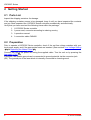
2 Getting Started
2.1 Parts List
Inspect the shipping container for damage.
If the shipping container seems to be damaged, keep it until you have inspected the contents
and you have inspected the LDC200C Series controller mechanically and electrically.
Verify that you have received the following items within the package:
1. 1 LDC200C Series controller
2. 1 power cord, connector according to ordering country
3. 1 operation manual
4. 1 connection cable CAB400
2.2 Preparation
Prior to operate a LDC200C Series controller, check if the set line voltage matches with your
local power supply and if the appropriate fuses are inserted. (See sections Line Voltage Setting
20 and Replacing the Mains Fuses 21 )
Connect the unit to the power line using the supplied cable. Turn the unit on by pressing the
line switch (F10) 9 .
If required, the chassis ground can be connected to ground potential via the connector jack
(R5). The ground pin of the laser diode is internally connected to chassis ground.
8
© 2014 Thorlabs
2 Getting Started
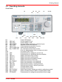
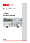
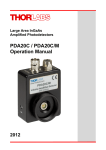
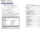
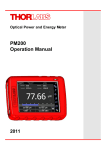
2.3 Operating elements
Front Panel
F1
F2
F3
F4
F5
F6
F7
F8
F9
F10
F11
F12
F13
F14
F15
F16
F17
F18
F19
F20
F21
F22
F23
F24
F25
LED "mA"
LED "mW"
LED "OPEN"
LED "LIMIT"
LED "OTP"
LED "LASER ON"
Key "LASER ON"
LIM I
CAL
LED "ILD"
LED "PLD"
LED "IPD"
LED "ILIM"
Key “DOWN”
Key “UP”
LED "AG"
LED "CG"
LED "P"
LED "I"
Key "LD POL"
Key "CONST"
PD RANGE
© 2014 Thorlabs
5-digit LED display
Current display in mA
Power display in mW
No laser diode connected, or Interlock open
Adjusted current limit reached
Overtemperature protection is active
Laser current is switched on
On / Off switch for the laser current
Knob for adjusting the current or power set value
Line switch (ON / OFF)
Potentiometer for setting the current limit
Potentiometer for calibrating the power display
Display shows the laser current
Display shows the optical power
Display shows the photodiode current
Display shows the current limit
Select the parameter to be displayed
Select the parameter to be displayed
Selected laser polarity: anode grounded
Selected laser polarity: cathode grounded
Constant power mode
Constant current mode
Select laser polarity: anode grounded or cathode grounded
Select constant current mode or constant power mode
Potentiometer for setting the photodiode current range
9
LDC200C Series
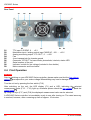
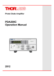
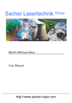
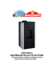
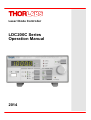
Rear Panel
R1
R2
R3
R4
R5
R6
R7
R8
R9
TTL input “LD REM”, 0 … +5 V
Modulation input / analog control input "MOD IN", -10V … +10 V
Analog monitoring output "CTL OUT", 0 … ±10V
Fan
4 mm banana jack for chassis ground
Connector "LD OUT" for laser diode, photodiode, interlock, status LED
Serial number of the unit
Indicator / switch for line voltage (included in fuse holder)
Mains connector and fuse holder
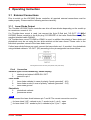
2.4 First Operation
Attention
Prior to switching on your LDC200C Series controller, please make sure that the line voltage
setting 20 corresponds to your mains voltage! Mismatching may lead to damage of the
controller!
Turn the unit on by pressing the line switch (F10).
After switching on the unit, the LED display (F1) and a LED, indicating the selected
measurement value (F13 ... F16), light up, otherwise please check the line voltage 20 and the
mains fuses 21 .
By using the keys (F17) and (F18) the displayed measurement value can be selected.
A LDC200C Series controller is immediately ready to use after turning on. The rated accuracy
is reached, however, after a warming-up time of approx. 10 minutes.
10
© 2014 Thorlabs
3 Operating Instruction
3 Operating Instruction
3.1 External Connections
Prior to switch on the LDC200C Series controller, all required external connections must be
made properly. Please read the following sections carefully.
3.1.1 Laser Diode Output
The Thorlabs LDC200C Series controller can drive all laser diodes depending on the model up
to a maximum current of 4 A.
If a Thorlabs laser mount is used, just connect the 9-pin D-Sub jack "LD OUT" (R6) 10 of
LDC200C Series controller to the 9-pin plug "LD DRIVER" of the Laser Diode Mount using the
supplied shielded cable CAB400.
If a Thorlabs laser mount TCLDM9 or LDM21 is used, in addition the polarity of laser diode and
photodiode must be set using the two slide switches at the laser mount. Please refer to the
individual operation manual of the laser diode mount.
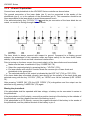
If other laser diode fixtures are used, connect the laser diode and - if provided - the photodiode
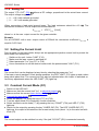
using shielded cables to "LD OUT" (R6) according to the pin assignment as shown below:
Pin assignment of the "LD OUT" j ack (female, rear panel view)
Pin # Connection
Interlock (open circuit monitoring, status display)
1
interlock and status LASER ON / OFF
5
ground for pin 1
Laser Diode
7
laser diode cathode (in case of polarity "anode grounded" - AG)
8
laser diode anode (in case of polarity "cathode grounded" - CG)
3
laser diode ground
Photodiode
2
photodiode cathode
4
photodiode anode
Note
Do not connect the laser diode between pin 7 and 8! The correct connection must be:
for laser diode "AG": cathode to pin 7, anode to pin 3, pin 8 - open
for laser diode "CG": anode to pin 8, cathode to pin 3, pin 7 - open.
© 2014 Thorlabs
11
LDC200C Series
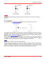
3.1.2 LD and PD polarities
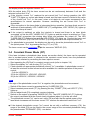
Connect laser and photodiode to the LDC200C Series controller as shown below.
The ground connection of the laser diode (pin 3) can be connected to the anode of the
photodiode (pin 4), or to the cathode of the photodiode (pin 2). This connection should be as
close as possible to the laser diode to avoid measurement errors.
If the selected polarity (key "LD POL" F23 9 ) and the pin connection of the laser diode do not
match, no current is flowing through the laser diode.
The laser diode is always sourced with respect to ground. Compared to a floating ground
scheme, the advantages of this operation mode are higher safety for the laser diode, better
stability of the laser current and less introduced interferences.
Prior to turning on the laser current, the correct polarity of the laser diode must be selected:
Make sure the laser is switched off (key “LASER ON” F8).
Select the required polarity by pressing the key "LD POL" (F23).
For laser diodes with a built-in monitor diode the common pin of laser diode and
photodiode is the ground pin.
The selected polarity of the output is indicated by the LED "AG" (F19) or "CG" (F20).
If the laser diode was connected correctly (see above) but the polarity of the laser diode was
selected wrong with the key “LD POL” (F23), an “OPEN” error will be indicated (LED “OPEN”
F4).
After pressing "LASER ON" (F8) the LED "OPEN" (F4) extinguishes and the output can be
switched on by pressing "LASER ON" (F8) again.
Biasing the photodiode
If the photodiode shall be operated with bias voltage, a battery can be connected in series to
the photodiode.
If the photodiode is of AG polarity, connect the positive terminal of the battery to the cathode of
the photodiode, and the negative terminal of the battery to pin 2.
If the photodiode is of CG polarity, connect the negative terminal of the battery to the anode of
the photodiode, and the positive terminal of the battery to pin 4.
12
© 2014 Thorlabs
3 Operating Instruction
Attention
A wrong polarity of the battery may destroy the photodiode due to a forward current flowing
through it!
3.1.3 Interlock
Pin 1 and pin 5 of the "LD OUT" jack (R6)
11
are the interface of the interlock circuit.
The interlock output represents a current source, while the voltage across the external circuit,
connected to pin 1 and 5, is being observed. As soon as this voltage rises above a certain
threshold (~2.5V), the external circuit is considered as "open", the laser current output is
disabled and the LED "OPEN" (F4) 9 lights up .
Pin 1 and pin 5 must be connected externally by a short cut wire, by a circuit (total resistance
<430 ) or by a LED (anode to pin 1, cathode to pin 5, connect in parallel resistor R=1 k ). A
connected LED lights up when the laser current is switched on (LASER ON).
Note
Do not use blue LED due to their high forward voltage
Thorlabs Laser Diode Mounts use the interlock current for indication "LD ON". When using a
Thorlabs TCLDM9 or LM14S2 laser diode mount, interlock functionality can be easily used for
emergency switch-off of the laser by connecting an opening contact to the jack located on the
laser mount. For details, please refer to the appropriate laser diode mount manual.
© 2014 Thorlabs
13
LDC200C Series
3.1.4 Analog Out
The output "CTL OUT" (R3) 10 delivers a DC voltage, proportional to the actual laser current.
The output voltage ranges from:
0 …+10 V with cathode grounded
0 … -10 V with anode grounded.
When connecting a load avoid ground loops. The load resistance should be >10 k . The
conversion coefficient for this output can be calculated to:
kCTL OUT = 10V/Imax [V/mA]
where Imax is the max. output current for the given controller.
Example:
For an LDC202C with a max. output current of 200mA the conversion coefficient kCTL OUT is
equal to 0.05 V/mA.
3.2 Setting the Current Limit
Prior to switch on the laser diode, always set an appropriate injection current limit to protect the
laser diode from destruction:
Switch on the unit - button "LINE" (F10).
Make sure the laser current is switched off
Select parameter "ILIM" (key F17 or F18).
Use a screwdriver to set the desired current with the potentiometer "LIM I" (F11).
Note
The current limit can be displayed at any time by selecting the parameter "ILIM"
If the laser current reaches it's limit during operation, the LED "LIMIT" (F5) lights up and a short
beep alerts about that. The current limit can also be adjusted when the output is switched on.
Avoid any adjustments when the LED "LIMIT" (F5) lights up.
3.3 Constant Current Mode (CC)
Switch on the LDC2xxC.
Make sure, that the current limit "ILIM" is adjusted properly 14 .
Make sure that the correct laser diode polarity 12 is set.
Connect the laser diode 12 .
Select the display "ILD" using the keys (F17) or (F18).
Turn the adjust knob (F9) completely counter clockwise.
Select constant current mode (“I”) by pressing the key “CONST” (F24) until LED "I" (F22)
lights up.
Switch on the output by pressing the key "LASER ON" (F8). The LED "LASER ON" (F7)
lights up, the output is activated and the current slowly rises (about 1 s) to the value set with
knob (F9).
Note
The current output can be switched on only if the jack "LD OUT" (R6) is connected correctly
14
© 2014 Thorlabs
3 Operating Instruction
The display shows the injection current "ILD".
With the adjust knob (F8) the laser current can be set continuously between 0 mA and the
selected current limit "ILIM".
If the injection current "ILD" reaches the set current limit "ILIM" during operation, the LED
"LIMIT" (F5) lights up, a short alert beep is heard, and the laser current is limited to the value
of the current limit "ILIM". In this case, noise a nd ripple do not longer correspond to the
specifications for normal operation. However exceeding the set current limit "ILIM" is
impossible.
If the connection to the laser diode is interrupted during operation, the laser diode current is
switched off automatically. LED "LASER ON" (F7) extinguishes, LED "OPEN" (F4) lights up
and a short beep is heard.
If the output is switched on while the interlock is closed and there is no laser diode
connected, at first the LED "LASER ON" (F7) lights up and the output is switched on. Then
the LDC2xxC recognizes the missing laser diode and switches the output off. The LED
"LASER ON" (F7) extinguishes and the LED "OPEN" (F4) lights up. Connect the laser and
press "LASER ON" (F8) - the LED "OPEN" (F4) extinguishes and the output switches on.
If a photodiode is connected, the display can be set to show the photodiode current "IPD" or
the optical power "PLD" by pressing the key (F17) or (F18).
The laser current can be modulated
17
via the connector "MOD IN" (R2).
3.4 Constant Power Mode (CP)
If the laser includes a photodiode (also known as monitor diode), the laser can be operated
also in constant power mode. In contrast to the constant current mode, here the photodiode
current is kept constant by controlling the laser injection current.
Start operating the LDC2xxC in constant current mode (refer to chapter 3.4)
Select the display "IPD" with the key (F17) or (F18).
Check whether an appropriate photodiode current "IPD" is available. A photodiode current of
at least the minimum control current must be available for a stable operation of the power
control:
5 µA for LDC200CV,
25 µA for LDC201CU, LDC202C, LDC205C,
50 µA for LDC210C, LDC220C, LDC240C.
Note
If the sign of the photodiode current "IPD" is negative, the photodiode must be reversed.
Switch off the laser current by pressing the key "LASER ON" (F8) .
Select constant power mode (“P”) by pressing the key “CONST” (F24) until LED "P" (F21)
lights up.
Set the adjust knob (F9) completely counter clockwise.
Switch on the output by pressing "LASER ON" (F8). The LED "LASER ON" (F7) lights up,
the output is activated and the current slowly increases (about 1 s) to the set value.
The photodiode current "IPD" can be set using (F9) and with that the optical power of the
laser diode increases until the laser current "ILD" reaches the selected current limit "ILIM".
If the desired photodiode current "IPD" cannot be set with a sufficient accuracy (F9), the
range of the knob (F9) can be fitted to the current range of the connected photodiode using
the potentiometer "PD RANGE" (F25) - see below.
© 2014 Thorlabs
15
LDC200C Series
If no photodiode is connected or the polarity of the photodiode is set wrong, the laser current
"ILD" increases to the limit "ILIM" after the output is switched on.
If the connection to the photodiode is interrupted in constant power mode, the laser current
"ILD" increases to the set current limit "ILIM".
If the injection current "ILD" is limited by the selected current limit "ILIM", ripple and noise do
not longer correspond to the specifications for normal operation. However, the set maximum
current "ILIM" cannot be exceeded.
If the connection to the laser diode is interrupted during operation, the output is switched off
automatically. LED "LASER ON" (F7) extinguishes, LED "OPEN" (F4) lights up and a short
beep is heard.
If the output is switched on while the interlock is closed and there is no laser diode
connected, at first the LED "LASER ON" (F7) lights up and the output switches on. Then the
LDC2xxC recognizes the missing laser diode, switches the output off, the LED "LASER
ON" (F7) extinguishes and the LED "OPEN" (F4) lights up. Connect the laser, then press
"LASER ON" (F8) - the LED "OPEN" (F4) extinguishes and the laser diode current output
switches.
The laser current can be modulated via the connector "MOD IN" (R3) - see section External
Analog Modulation 17 .
Changing the "IPD" setting range
With potentiometer "PD RANGE" (F25) the full scale of the adjustment knob (F9) can be set in
order to ease the setting of the operating point in constant power mode even with low
photodiode current. The photodiode current range depends on the type of the LDC2xxC
controller:
LDC200CV: 0.6 mA to 2 mA
LDC201CU, LDC202C, LDC205C: 3 mA to 10 mA
LDC210C, LDC220C, LDC240C: 6 mA to 20 mA
Turn the potentiometer "PD RANGE" (F25) completely counter clockwise.
Turn the adjust knob (F9) completely counter clockwise.
Select constant power mode “P” (key “CONST” F24), connect the laser diode and the
photodiode and switch on the laser current by pressing the key “LASER ON” (F8).
Set the desired photodiode current with the knob (F9).
If the desired operating point cannot be reached even if the knob (F9) is turned completely
clockwise (i.e. IPD > 0.6 mA), turn the potentiometer "PD RANGE" (F25) clockwise until the
desired setting range has been reached.
Note
A change of the "PD RANGE" (F25) leads to a change of the power set value in CP mode. In
constant current mode the potentiometer "PD RANGE" is without function.
3.5 Calibration of Optical Power Display
Additionally to the photodiode current "IPD", the optical power of the laser diode can be
displayed. To achieve a correct optical power display, a calibration (potentiometer "CAL" - F12)
must be carried out:
Select constant current mode “I” - key “CONST” (F24).
16
© 2014 Thorlabs
3 Operating Instruction
With the knob (F8), set the laser current "ILD" to an operating point for which the optical
output power of the laser diode is known, e.g. from the data sheet of the laser diode. You
may also find this operating point by displaying the monitor current "IPD" (F15). A more
accurate way is to measure the laser power using an optical power meter.
Select the display "PLD" (F14) - keys (F17) or (F18).
Turn the potentiometer "CAL" (F12) completely counter clockwise.
Select the range at which the displayed power is least higher than the actual optical power:
Press the key “CONST” (F24). While holding it, press the key “Down” (F17). With every
keystroke, the decimal point of the display moves to the left. Pressing the key “Up” (F18), the
decimal point moves to the right. After reaching the highest range, the decimal point jumps
back to the left-most position.
Calibrate the display "PLD" to the value of the actual optical power by adjusting the
potentiometer "CAL" (F12) clockwise.
3.6 External Analog Modulation
To generate a time dependent injection current "ILD" or photodiode current "IPD", these settings
can be modulated via an independent ground-symmetric modulation input "MOD IN" (R2).
Maximum allowed input voltage is –10 V … +10 V, input resistance is >10 k .
"ILD" and "IPD" are calculated as:
ILD = ILD SET + ILD MAX * UMOD / 10 V (in constant current mode)
or
IPD = IPD SET + IPD MAX * UMOD / 10 V (in constant power mode)
with:
ILD MAX:
Maximum laser current (e.g. 500 mA for LDC205C)
IPD MAX:
Max. photodiode current (e.g. 10 mA for LDC205C; see Control
Ranges in “Technical Data 24 ”)
ILD SET or IPD SET: value set with knob (F9)
UMOD:
voltage at input "MOD IN" (R2)
Start operation in constant current or constant power mode (refer to chapter 3.4 or 3.5) and
adjust the desired set value with the knob (F9).
Connect the modulation source to the jack "MOD IN" (R2). Avoid ground loops when
connecting the function generator.
The laser diode current "ILD" can be monitored at the analog output "CTL OUT" (R3)
14
.
If the injection current "ILD" reaches the current limit "ILIM" in operation, the LED "LIMIT" (F5)
lights up, a short beep is heard, and the laser current is limited to the value of the current limit
"ILIM". In this case, ripple and noise do no longer correspond to the specifications for normal
operation. However the set maximum current "ILIM" cannot be exceeded.
3.7 Overtemperature Protection
The LDC200C Series controllers come with an internal over-temperature protection. If the
internal heat sink is overheated, the output of the controller is disabled automatically. The LED
"OTP" (F6) lights up and a short beep is heard. The laser diode current is switched off
immediately. Pressing the key "LASER ON" (F8) has no effect in this case.
After the internal heat sink's temperature decreased for about 10°C, the LED "OTP" (F6)
extinguishes and the laser current output can be switched on again.
© 2014 Thorlabs
17
LDC200C Series
3.8 Disabling the Beeper
If audible signals are unwanted, the beeper can be disabled in this way:
Press and hold the key “UP” (F18).
Press the key “Down” (F17). Now the beeper state is displayed:
“Sd.On” - Sound ON
“Sd.OFF” - Sound OFF
To change the beeper state, hold the key “UP” pressed and toggle the beeper state by pressing
"DOWN" key.
3.9 Remote Operation
Although the LDC200C Series Controllers do not provide a standard computer interface, a
limited remote operation is possible using the TTL input or the analog inputs and outputs.
The following control or read out functions are available:
LD REM
This digital input allows to switch on/off the laser independent of the key “LASER ON”. A rising
edge at this input switches the laser on (if being in off state), a falling edge switches the laser
off (if being in on state). The threshold voltages are TTL compatible and feature hysteresis.
When using the “LD REM” input, the key “LASER ON” remains fully functional.
Interlock
If a relay contact or an open collector transistor is inserted into the interlock line (refer to section
"Interlock 13 "), the output can be switched off remotely at any time.
Note
The interlock is usable only for switching off. After the interlock path was interrupted, the
LDC200C Series Controller can be switched on again only manually, provided the Interlock is
closed.
Setting the laser diode current
The analog modulation input “MOD IN” input (R2) is DC coupled; the input voltage ranges from
-10V to + 10V. The input resistance of the input “MOD IN” is >10 k .
A voltage applied to this input is converted to a current value, which is then superposed to the
LD set value, adjusted with the rotary knob F9. The conversion coefficient depends on the max.
nominal output current of the controller and can be calculated to
kMOD = Imax /10V [mA/V]
where Imax is the max. output current for the given controller.
Example:
For a LDC202C with a max. output current of 200mA the conversion coefficient kMOD is equal to
20mA/V.
If the adjusting knob (F9) is set to it's left stop position, corresponding to a zero injection
current, the laser diode set current value can be controlled externally by an analog DC voltage
of (0...+10) V applied to the “MOD IN” input (R2).
18
© 2014 Thorlabs
3 Operating Instruction
If knob F9 is at its right stop position (corresponding to the max. injection current), a DC voltage
of (-10…0) V can be used to decrease the injection current.
Note
The laser current output must be switched on, otherwise a current control via MOD IN is
impossible.
Monitoring the laser current
The output "CTL OUT" (R3) 10 delivers a DC voltage, proportional to the actual laser current.
The output voltage ranges from:
0 …+10 V with cathode grounded
0 … -10 V with anode grounded.
Load resistance should be >10 k . The conversion coefficient
multiplicative inverse of kMOD:
for this output is the
kCTL OUT = 10V/Imax [V/mA]
Note
All operating elements of the LDC2xxC are active at any time. For remote operation, make sure
that the manual settings are not changed during operation.
© 2014 Thorlabs
19
LDC200C Series
4 Maintenance and Service
Protect the LDC200C Series from adverse weather conditions. The LDC200C Series is not
water resistant.
Attention
To avoid damage to the instrument, do not expose it to spray, liquids or solvents!
The unit does not need a regular maintenance by the user. If necessary the unit and the display
can be cleaned with a cloth dampened with water. A mild 75% Isopropyl Alcohol solution can
be used for more efficient cleaning.
LDC200C Series Controllers do not contain any modules and/or components that could be
repaired by the user himself. If a malfunction occurs, please contact Thorlabs 36 for return
instructions.
Do not remove covers!
To guarantee the specifications given in section Technical Data
recommended to have the unit factory calibrated every two years.
24
over a long period it is
4.1 Line Voltage Setting
The laser diode controller LDC2xxC operates at fixed line voltages of
100 V +15% / -10% ( 90 V … 115 V)
115 V +15% / -10% (104 V … 132 V)
230 V +15% / -10% (207 V … 264 V)
line frequency 50 … 60 Hz.
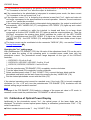
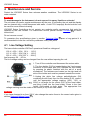
The line voltage setting can be changed from the rear without opening the unit.
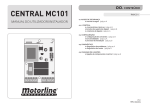
1. Turn off the controller and disconnect the mains cable.
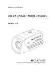
2. The fuse holder (R10) is located below the 3-pole power
connector of the mains jack (R9). Release the fuse holder
by pressing its plastic retainers with the aid of a small
screwdriver. The retainers are located on the right and left
side of the holder and must be pressed towards the center.
3. Unplug the white line voltage switch/indicator (R8,
containing the left fuse) from the fuse holder (R10), rotate it
until the appropriate voltage marking (100V, 115V, or
230V) is on target for the cutout (R12) of the fuse holder,
and plug it back into the fuse holder. Press in the fuse
holder until locked on both sides. The appropriate line
voltage marking must be visible in the cutout (R12) of the fuse holder.
Attention
If you have changed to or from 230 V, also change the mains fuses to the correct value given in
section Replacing Mains Fuses 21 .
20
© 2014 Thorlabs
4 Maintenance and Service
4.2 Replacing Mains Fuses
The two power input fuses are externally accessible. If they blew due to line distortions,
incorrect line voltage or other causes, they can be replaced from the rear without opening the
unit.
Attention
To avoid risk of fire only the appropriate fuses for the corresponding line voltage must be used
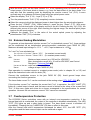
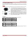
1. Turn off the LDC2xxC and disconnect the mains cable.
2. The fuse holder (R10) is located below the 3-pole power
connector of the mains jack (R9). Release the fuse holder by
pressing its plastic retainers using a small screwdriver. The
retainers are located on the right and left side of the holder
and must be pressed towards the center.
3. Replace the defective fuses (R11) and press in the fuse
holder until locked on both sides. Take care to maintain the
correct rotation of the white line voltage indicator / switch (R8)
which contains the left fuse and is plugged into the fuse
holder. The appropriate line voltage marking must be visible in
the cutout (R12) of the fuse holder.
Fuse types
LDC200VC, LDC201CU, LDC202C, LDC205C, LDC210C, and LDC220C:
100 V
500 mA, time-lag, 250V
T0.5A250V
115 V
500 mA, time-lag, 250V
T0.5A250V
230 V
250 mA, time-lag, 250V
T0.25A250V
100 V
800 mA, time-lag, 250V
T0.8A250V
115 V
800 mA, time-lag, 250V
T0.8A250V
230 V
400 mA, time-lag, 250V
T0.4A250V
LDC240C:
All fuses must meet IEC specification 60127-2/III, time characteristic: time-lag (T), 250V AC,
size 5 x 20 mm.
© 2014 Thorlabs
21
LDC200C Series
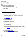
4.3 Troubleshooting
In case that your LDC200C Series Controller shows malfunction please check the following
items:
Unit does not work at all (no display at the front):
o LDC2xxC connected properly to the mains?
Check the power cord and the line voltage setting
20
o LDC2xxC turned on?
Turn on your LDC200C Series Controller (button "LINE" F10).
o Check the fuses 21 at the rear panel.
If blown, replace the fuses with the correct type.
The desired laser output power cannot be achieved
o Is the interlock closed?
Check the connection of interlock
13
pins of the connector jack.
o Is the laser output turned on ("LASER ON" button)?
Change the setting from “OFF” to “ON”. The LED “ON” on the front panel of the
mainframe must light up.
o Is the current limit ILIM set to 0?
Adjust the hardware limit I 14 LIM
appropriate value.
14
(potentiometer on the front panel) to an
o Is the laser diode installed properly?
Check the connection cable.
o Is the polarity of the laser diode set correctly?
If not change the polarity of the diode or select on the LDC2xxC the opposite polarity
12 .
o Is the photodiode connected properly?
Check the connection cable.
o Is the photodiode poled correctly?
If in constant power mode the displayed photodiode current is negative, the polarity
of the photodiode must be reverted.
o Are you using a bias voltage 12 with the photodiode in photo current mode?
Change the polarity of the diode for photo element mode or change the polarity of the
bias voltage source.
o Is the desired output power set correctly?
Check the optical power display calibration 16
Adjust the desired output power PLD using the tuning knob.
22
© 2014 Thorlabs
4 Maintenance and Service
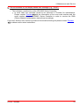
The unit switches on, but display shows error message (e.g., “Err06”)
o This indicates a malfunction of the LDC200C Series Controller.
In such case, the controller needs to be returned to Thorlabs for maintenance.
Please contact Thorlabs 36 with the information of the error code number and the
serial number of your LDC200C Series Controller in order to receive the RMA
(Return Material Authorization) instructions accordingly.
If you don’t find the error source by means of the trouble shooting list please contact Thorlabs
36 for advise and/or return instructions
© 2014 Thorlabs
23
LDC200C Series
5 Appendix
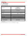
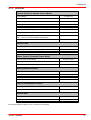
5.1 Technical Data
Common Technical Data
General Data
Safety Features
Display
Connector for Laser, Photodiode, Interlock &
Laser On Signal
Connectors for Control Input / Output
Chassis Ground Connector
Line Voltage
Mains Supply Overvoltage
Line Frequency
Operating Temperature Range 1)
Storage Temperature Range
Relative Humidity
Pollution Degree (Indoor Use only)
Operation Altitude
Warm-up Time for Rated Accuracy
Dimensions (W x H x D)
w/o Operating Elements
with Operating Elements
1)
Interlock
Laser Current Limit
Soft Start
Short Circuit when Laser off
Open Circuit Detection
Overtemperature Protection
LED, 5 Digits
9-pin D-Sub Jack
BNC
4mm Banana Jack
100 V
115 V
+15% / –10%
230 V
Category II (Cat II)
50 to 60 Hz
0°C to +40 °C
-40°C to +70 °C
Max. 80% up to 31 °C, decreasing to 50% at 40 °C
2
<2000 m
10 min
146 x 66 x 290 mm³
146 x 77 x 320 mm³
non-condensing
All technical data are valid at 23 ± 5°C and 45 ± 15% rel. humidity (non condensing)
24
© 2014 Thorlabs
5 Appendix
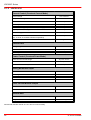
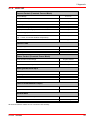
5.1.1 LDC200CV
Current Control (Constant Current Mode)
Control Range
Compliance Voltage
0 to ±20 mA
>6 V
Resolution
1.0 µA
Accuracy
±20 µA
Noise Without Ripple (10Hz to 10MHz, rms, typ.)
<1.0 µA
Ripple (50/60Hz, rms, typ.)
<0.5 µA
Transients (typ.)
<10 µA
Drift, 24hours
(typ., 0-10Hz, at constant ambient temperature)
<1 µA
Temperature Coefficient
<50 ppm/°C
Current Limit
Setting Range
Resolution
Accuracy
0 to >20 mA
1 µA
± 50 µA
Power Control (Constant Power Mode)
Photo Current Control Range
5 µA to 2 mA
Photo Current Resolution
0.1 µA
Photo Current Accuracy
±2 µA
Analog Modulation Input
Input Resistance
Small Signal 3dB Bandwidth, CC Mode
10 kΩ
DC to 100 kHz
Modulation Coefficient, CC Mode
2 mA/V ±5%
Modulation Coefficient, CP Mode
0.2 mA/V ±5%
Laser Current Monitor Output
Load Resistance
Transmission Coefficient
>10 kΩ
500 V/A ±5%
General data
Maximum Power Consumption
Weight
20 VA
<3.1 kg
All technical data are valid at 23 ± 5°C and 45 ±15% humidity
© 2014 Thorlabs
25
LDC200C Series
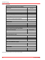
5.1.2 LDC201CU
Current Control (Constant Current Mode)
Control Range
0 to ±100 mA
Compliance Voltage
>5 V
Resolution
10 µA
Accuracy
±50 µA
Noise Without Ripple (10Hz to 10MHz, rms, typ.)
<0.2 µA
Ripple (50/60Hz, rms, typ.)
<0.5 µA
Transients (typ.)
<10 µA
Drift, 24hours
(typ., 0-10Hz, at constant ambient temperature)
<2 µA
Temperature Coefficient
<50 ppm/°C
Current Limit
Setting Range
Resolution
Accuracy
0 to >100 mA
10 µA
± 200 µA
Power Control (Constant Power Mode)
Photo Current Control Range
Photo Current Resolution
Photo Current Accuracy
25 µA to 10 mA
1 µA
±10 µA
Analog Modulation Input
Input Resistance
10 kΩ
Small Signal 3dB Bandwidth, CC Mode
DC to 0.2 kHz
Modulation Coefficient, CC Mode
10 mA/V ±5%
Modulation Coefficient, CP Mode
1 mA/V ±5%
Laser Current Monitor Output
Load Resistance
Transmission Coefficient
>10 kΩ
100 V/A ±5%
General data
Maximum Power Consumption
Weight
20 VA
<3.1 kg
All technical data are valid at 23 ± 5°C and 45 ±15% humidity
26
© 2014 Thorlabs
5 Appendix
5.1.3 LDC202C
Current Control (Constant Current Mode)
Control Range
0 to ±200 mA
Compliance Voltage
>10 V
Resolution
10 µA
Accuracy
±100 µA
Noise Without Ripple (10Hz to 10MHz, rms, typ.)
<1.5 µA
Ripple (50/60Hz, rms, typ.)
<1.5 µA
Transients (typ.)
<0.2 mA
Drift, 24hours
(typ., 0-10Hz, at constant ambient temperature)
Temperature Coefficient
<3 µA
<50 ppm/°C
Current Limit
Setting Range
Resolution
Accuracy
0 to >200 mA
10 µA
± 500 µA
Power Control (Constant Power Mode)
Photo Current Control Range
Photo Current Resolution
Photo Current Accuracy
25 µA to 10 mA
1 µA
±10 µA
Analog Modulation Input
Input Resistance
10 kΩ
Small Signal 3dB Bandwidth, CC Mode
DC to 250 kHz
Modulation Coefficient, CC Mode
20 mA/V ±5%
Modulation Coefficient, CP Mode
1 mA/V ±5%
Laser Current Monitor Output
Load Resistance
Transmission Coefficient
>10 kΩ
50 V/A ±5%
General data
Maximum Power Consumption
Weight
25 VA
<3.1 kg
All technical data are valid at 23 ± 5°C and 45 ±15% humidity
© 2014 Thorlabs
27
LDC200C Series
5.1.4 LDC205C
Current Control (Constant Current Mode)
Control Range
0 to ±500 mA
Compliance Voltage
>10 V
Resolution
10 µA
Accuracy
±0.5 mA
Noise Without Ripple (10Hz to 10MHz, rms, typ.)
< 3 µA
Ripple (50/60Hz, rms, typ.)
< 2 µA
Transients (typ.)
Drift, 24hours
(typ., 0-10Hz, at constant ambient temperature)
Temperature Coefficient
< 0.5 mA
<10 µA
<50 ppm/°C
Current Limit
Setting Range
Resolution
Accuracy
0 to >500 mA
10 µA
±1.5 mA
Power Control (Constant Power Mode)
Photo Current Control Range
Photo Current Resolution
Photo Current Accuracy
25 µA to 10 mA
1 µA
±10 µA
Analog Modulation Input
Input Resistance
10 kΩ
Small Signal 3dB Bandwidth, CC Mode
DC to 150 kHz
Modulation Coefficient, CC Mode
50 mA/V ±5%
Modulation Coefficient, CP Mode
1 mA/V ±5%
Laser Current Monitor Output
Load Resistance
Transmission Coefficient
>10 kΩ
20 V/A ±5%
General data
Maximum Power Consumption
Weight
30 VA
<3.1 kg
All technical data are valid at 23 ± 5°C and 45 ±15% humidity
28
© 2014 Thorlabs
5 Appendix
5.1.5 LDC210C
Current Control (Constant Current Mode)
Control Range
0 to ±1 A
Compliance Voltage
>10 V
Resolution
100 µA
Accuracy
±1.0 mA
Noise Without Ripple (10Hz to 10MHz, rms, typ.)
<5 µA
Ripple (50/60Hz, rms, typ.)
<3 µA
Transients (typ.)
<1 mA
Drift, 24hours
(typ., 0-10Hz, at constant ambient temperature)
<20 µA
Temperature Coefficient
<50 ppm/°C
Current Limit
Setting Range
Resolution
Accuracy
0 to >1 A
100 µA
± 2.5 mA
Power Control (Constant Power Mode)
Photo Current Control Range
Photo Current Resolution
Photo Current Accuracy
50 µA to 20 mA
1 µA
±20 µA
Analog Modulation Input
Input Resistance
10 kΩ
Small Signal 3dB Bandwidth, CC Mode
DC to 100 kHz
Modulation Coefficient, CC Mode
100 mA/V ±5%
Modulation Coefficient, CP Mode
2 mA/V ±5%
Laser Current Monitor Output
Load Resistance
Transmission Coefficient
>10 kΩ
10 V/A ±5%
General data
Maximum Power Consumption
Weight
40 VA
<3.1 kg
All technical data are valid at 23 ± 5°C and 45 ±15% humidity
© 2014 Thorlabs
29
LDC200C Series
5.1.6 LDC220C
Current Control (Constant Current Mode)
Control Range
Compliance Voltage
0 to ±2 A
>4 V
Resolution
100 µA
Accuracy
±2.0 mA
Noise Without Ripple (10Hz to 10MHz, rms, typ.)
<15 µA
Ripple (50/60Hz, rms, typ.)
<5 µA
Transients (typ.)
<2 mA
Drift, 24hours
(typ., 0-10Hz, at constant ambient temperature)
Temperature Coefficient
<100 µA
<50 ppm/°C
Current Limit
Setting Range
0 to >2 A
Resolution
100 µA
Accuracy
± 5 mA
Power Control (Constant Power Mode)
Photo Current Control Range
Photo Current Resolution
Photo Current Accuracy
50 µA to 20 mA
1 µA
±20 µA
Analog Modulation Input
Input Resistance
Small Signal 3dB Bandwidth, CC Mode
10 kΩ
DC to 50 kHz
Modulation Coefficient, CC Mode
200 mA/V ±5%
Modulation Coefficient, CP Mode
2 mA/V ±5%
Laser Current Monitor Output
Load Resistance
Transmission Coefficient
>10 kΩ
5 V/A ±5%
General data
Maximum Power Consumption
Weight
60 VA
<3.3 kg
All technical data are valid at 23 ± 5°C and 45 ±15% humidity
30
© 2014 Thorlabs
5 Appendix
5.1.7 LDC240C
Current Control (Constant Current Mode)
Control Range
Compliance Voltage
0 to ±4 A
>5 V
Resolution
100 µA
Accuracy
±4.0 mA
Noise Without Ripple (10Hz to 10MHz, rms, typ.)
<50 µA
Ripple (50/60Hz, rms, typ.)
<8 µA
Transients (typ.)
<4 mA
Drift, 24hours
(typ., 0-10Hz, at constant ambient temperature)
Temperature Coefficient
<200 µA
<50 ppm/°C
Current Limit
Setting Range
0 to >4 A
Resolution
100 µA
Accuracy
± 10 mA
Power Control (Constant Power Mode)
Photo Current Control Range
Photo Current Resolution
Photo Current Accuracy
50 µA to 20 mA
1 µA
±20 µA
Analog Modulation Input
Input Resistance
Small Signal 3dB Bandwidth, CC Mode
10 kΩ
DC to 30 kHz
Modulation Coefficient, CC Mode
400 mA/V ±5%
Modulation Coefficient, CP Mode
2 mA/V ±5%
Laser Current Monitor Output
Load Resistance
Transmission Coefficient
>10 kΩ
2.5 V/A ±5%
General data
Maximum Power Consumption
100 VA
Weight
<3.3 kg
All technical data are valid at 23 ± 5°C and 45 ±15% humidity
© 2014 Thorlabs
31
LDC200C Series
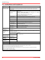
5.2 Certifications and Compliances
Category
Standards or description
EC Declaration of
Conformity - EMC
Meets intent of Directive 2004/108/EC 1 for Electromagnetic Compatibility. Compliance was
demonstrated to the following specifications as listed in the Official Journal of the European
Communities:
EN 61326: Apr.1997
+A1:1998 +A2:2001
+A3:2003
Electrical equipment for measurement, control and laboratory use – EMC
requirements:
Immunity: complies with immunity test requirements for equipment
intended for use in industrial locations 2,3.
Emission: complies with EN 55011 Class B Limits 2,3,4
IEC 61000-3-2 and IEC 61000-3-3.
IEC 61000-4-2
Electrostatic Discharge Immunity (Performance Criterion B)
IEC 61000-4-3
Radiated RF Electromagnetic Field Immunity (Performance Criterion A) 5
IEC 61000-4-4
Electrical Fast Transient / Burst Immunity (Performance Criterion A)
IEC 61000-4-5
Power Line Surge Immunity (Performance Criterion A)
IEC 61000-4-6
Conducted RF Immunity (Performance Criterion A)
IEC 61000-4-11
Voltage Dips, Short Interruptions and Voltage Variations Immunity
(Performance Criterion A)
IEC 61000-3-2
AC Power Line Harmonic Emissions
IEC 61000-3-3
Voltage Fluctuations and Flicker
FCC EMC
Compliance
Emissions comply with the Class B Limits of FCC Code of Federal Regulations 47, Part 15,
Subpart B 2,3,4.
EC Declaration of
Conformity - Low
Voltage
Compliance was demonstrated to the following specification as listed in the Official Journal of the
European Communities:
Low Voltage Directive 2006/95/EC 6
EN 61010-1:2010
Safety Requirements for Electrical Equipment for Measurement, Control
and Laboratory Use
U.S. Nationally
Recognized Testing
Laboratory Listing
UL 61010-1 2nd ed.
Canadian
Certification
CAN/CSA C22.2 No.
61010-1 4th ed.
Additional
Compliance
IEC 61010-1:2001
Equipment Type
Test and Measuring
Safety Class
Class I equipment (as defined in IEC60950-1:2001)
ISA-82:02.01
1
Replaces 89/336/EEC.
2
Compliance demonstrated using high-quality shielded interface cables shorter than or equal to 3 meters.
3
Compliance demonstrated with CAB400 cable installed at the LD OUT port.
4
Emissions, which exceed the levels required by these standards, may occur when this equipment is connected to a test object.
5
MOD IN port capped at IEC 61000-4-3 test.
6
Replaces 73/23/EEC, amended by 93/68/EEC
32
© 2014 Thorlabs
5 Appendix
5.3 Warranty
Thorlabs warrants material and production of the LDC200C Series for a period of 24 months
starting with the date of shipment. During this warranty period Thorlabs will see to defaults by
repair or by exchange if these are entitled to warranty.
For warranty repairs or service the unit must be sent back to Thorlabs. The customer will carry
the shipping costs to Thorlabs, in case of warranty repairs Thorlabs will carry the shipping costs
back to the customer.
If no warranty repair is applicable the customer also has to carry the costs for back shipment.
In case of shipment from outside EU duties, taxes etc. which should arise have to be carried by
the customer.
Thorlabs warrants the hard- and software determined by Thorlabs for this unit to operate faultfree provided that they are handled according to our requirements. However, Thorlabs does not
warrant a fault free and uninterrupted operation of the unit, of the software or firmware for
special applications nor this instruction manual to be error free. Thorlabs is not liable for
consequential damages.
Restriction of warranty
The warranty mentioned before does not cover errors and defects being the result of improper
treatment, software or interface not supplied by us, modification, misuse or operation outside
the defined ambient stated by us or unauthorized maintenance.
Further claims will not be consented to and will not be acknowledged. Thorlabs does explicitly
not warrant the usability or the economical use for certain cases of application.
Thorlabs reserves the right to change this instruction manual or the technical data of the
described unit at any time.
© 2014 Thorlabs
33
LDC200C Series
5.4 Copyright and Exclusion of Reliability
Thorlabs has taken every possible care in preparing this Operation Manual. We however
assume no liability for the content, completeness or quality of the information contained therein.
The content of this manual is regularly updated and adapted to reflect the current status of the
software. We furthermore do not guarantee that this product will function without errors, even if
the stated specifications are adhered to.
Under no circumstances can we guarantee that a particular objective can be achieved with the
purchase of this product.
Insofar as permitted under statutory regulations, we assume no liability for direct damage,
indirect damage or damages suffered by third parties resulting from the purchase of this
product. In no event shall any liability exceed the purchase price of the product.
Please note that the content of this User Manual is neither part of any previous or existing
agreement, promise, representation or legal relationship, nor an alteration or amendment
thereof. All obligations of Thorlabs result from the respective contract of sale, which also
includes the complete and exclusively applicable warranty regulations. These contractual
warranty regulations are neither extended nor limited by the information contained in this User
Manual. Should you require further information on this product, or encounter specific problems
that are not discussed in sufficient detail in the User Manual, please contact your local Thorlabs
dealer or system installer.
All rights reserved. This manual may not be reproduced, transmitted or translated to another
language, either as a whole or in parts, without the prior written permission of Thorlabs.
Copyright © Thorlabs 2014. All rights reserved.
34
© 2014 Thorlabs
5 Appendix
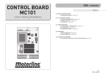
5.5 Thorlabs 'End of Life' Policy (WEEE)
As required by the WEEE (Waste Electrical and Electronic Equipment Directive) of the
European Community and the corresponding national laws, Thorlabs offers all end users in the
EC the possibility to return “end of life” units without incurring disposal charges.
This offer is valid for Thorlabs electrical and electronic equipment
sold after August 13th 2005
marked correspondingly with the crossed out “wheelie bin” logo (see figure below)
sold to a company or institute within the EC
currently owned by a company or institute within the EC
still complete, not disassembled and not contaminated
As the WEEE directive applies to self contained operational electrical and electronic products,
this “end of life” take back service does not refer to other Thorlabs products, such as
pure OEM products, that means assemblies to be built into a unit by the user (e. g. OEM
laser driver cards)
components
mechanics and optics
left over parts of units disassembled by the user (PCB’s, housings etc.).
Waste treatment on your own responsibility
If you do not return an “end of life” unit to Thorlabs, you must hand it to a company specialized
in waste recovery. Do not dispose of the unit in a litter bin or at a public waste disposal site.
WEEE Number (Germany) : DE97581288
Ecological background
It is well known that waste treatment pollutes the environment by releasing toxic products
during decomposition. The aim of the European RoHS Directive is to reduce the content of
toxic substances in electronic products in the future.
The intent of the WEEE Directive is to enforce the recycling of WEEE. A controlled recycling of
end-of-life products will thereby avoid negative impacts on the environment.
Crossed out
"Wheelie Bin" symbol
© 2014 Thorlabs
35
LDC200C Series
5.6 Thorlabs Worldwide Contacts
USA, Canada, and South America
Thorlabs, Inc.
56 Sparta Avenue
Newton, NJ 07860
USA
Tel: 973-579-7227
Fax: 973-300-3600
www.thorlabs.com
www.thorlabs.us (West Coast)
Email: [email protected]
Support: [email protected]
UK and Ireland
Thorlabs Ltd.
1 Saint Thomas Place, Ely
Cambridgeshire CB7 4EX
United Kingdom
Tel: +44-1353-654440
Fax: +44-1353-654444
www.thorlabs.com
Email: [email protected]
Support: [email protected]
Europe
Thorlabs GmbH
Hans-Böckler-Str. 6
85221 Dachau
Germany
Tel: +49-8131-5956-0
Fax: +49-8131-5956-99
www.thorlabs.de
Email: [email protected]
Scandinavia
Thorlabs Sweden AB
Mölndalsvägen 3
412 63 Göteborg
Sweden
Tel: +46-31-733-30-00
Fax: +46-31-703-40-45
www.thorlabs.com
Email: [email protected]
France
Thorlabs SAS
109, rue des Côtes
78600 Maisons-Laffitte
France
Tel: +33-970 444 844
Fax: +33-811 38 17 48
www.thorlabs.com
Email: [email protected]
Brazil
Thorlabs Vendas de Fotônicos Ltda.
Rua Riachuelo, 171
São Carlos, SP 13560-110
Brazil
Tel: +55-16-3413 7062
Fax: +55-16-3413 7064
www.thorlabs.com
Email: [email protected]
Japan
Thorlabs Japan, Inc.
Higashi Ikebukuro
Q Building 2nd Floor 2-23-2
Toshima-ku, Tokyo 170-0013
Japan
Tel: +81-3-5979-8889
Fax: +81-3-5979-7285
www.thorlabs.jp
Email: [email protected]
China
Thorlabs China
Room A101, No. 100
Lane 2891, South Qilianshan Road
Putuo District
Shanghai 200331
China
Tel: +86-21-60561122
Fax: +86-21-32513480
www.thorlabs.hk
Email: [email protected]
36
© 2014 Thorlabs