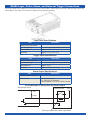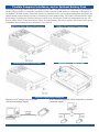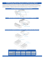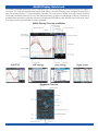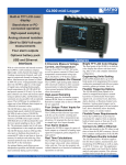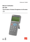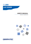
1
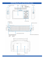
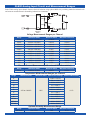
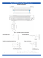
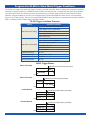
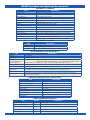
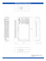
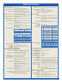
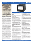
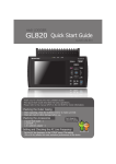
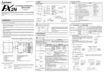
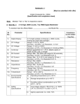
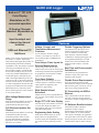
GL800 midi Logger
Built-in 5.7" TFT LCD
Color Display
Stand-alone or PCconnected operation
20 Analog Channels
Standard, Expandable to
200
Input-to-output and
channel-to-channel
Isolation
USB and Ethernet PC
Interfaces
Features
Voltage, Current, and
Temperature Measurement
Functions
Use the GL800 to measure voltages,
currents, 4-20 mA process currents, as
With its color monitor and internal memory well as thermocouple- and RTD-based
the GL800 is a compact, lightweight,
temperatures.
multi-channel data logger that provides 20
Four Unique ‘Pulse’ Inputs for
standard analog measurement channels,
expandable to 200. The GL800 is equipped Discrete Measurements
The GL800 provides discrete input
with a large internal flash memory to
channels that can be used for counting and
allow the direct capture of acquired data,
rotational speed measurement applications.
and its built-in USB port may be used to
Or program the discrete inputs as simple
connect any standard USB flash drive for
logic level input channels.
incremental capacity. Alternatively, the
USB or the integral Ethernet port may be
Four Alarm Outputs
connected to a PC to allow data upload in
Program the GL800 to trigger its openreal time or from memory, as well as local collector outputs as a function of analog
or remote configuration and real time data input signal level judgment, pulse
acquisition. The Ethernet feature includes
judgment, or logic pattern.
WEB and FTP server functions, which
Wide Sample Interval
allows monitoring from a remote location
as well as data transfer.
Selections
Sample intervals can be programmed to be
one of sixteen values ranging from 100 ms
Wide Voltage Measurement
to one hour.
Range
Each GL800 analog channel can measure
from 20 mV to 50 VFS across eleven
programmable measurement ranges.
Full Electrical Isolation Per
Channel
Each analog GL800 channel is electrically
isolated from all others and from
instrument ground to allow accurate
and safe measurements in industrial
applications where ground potential
differences are common.
Bright TFT LCD Color Display
The focal point of the GL800 is its built-in
5.7-inch color display that allows real
time trending, data review, and complete
instrument configuration.
Engineering Units Scaling
Each GL800 channel allows up to four
break points to be programmed for
accurate scaling into meaningful units like
psi, grams, newtons, gallons per minute,
etc.
Flexible Triggering Options
The GL800 allows data capture to be
started or stopped based upon signal
level, an external event, date/time,
alarm, duration, or Boolean channel
combinations. Analog signal triggers can
be programmed based upon level and
window tests: above threshold, below
threshold, inside window, or outside
window.
Real Time and Post-recorded
Calculations
The GL800 may be programmed to
calculate average value, peak value,
minimum value, and rms.
Flexible Power Requirements
Power the GL800 from its provided
international AC adaptor, from an optional
built-in battery pack, or from any 9 to 24
VDC source using an optional cable.
PC Connectivity via USB or
Ethernet
Allows data transfer to the PC either in
real time or from the GL800’s memory.
Also allows complete configuration of the
GL800.
PC Software Bundle Included
The GL800 includes a Windows
application for direct capture,
measurement, and monitoring of GL800
data. In addition to waveform and data
value capture and display, the application
can export data to an Excel file for further
analysis and report creation. The software
includes built-in help for quick reference.
DATAQ Instruments, Inc. • 241 Springside Drive • Akron, Ohio 44333 • Tel: 330-668-1444 • Email: [email protected] • www.dataq.com
GL800 Display, I/O, and Control Overview
330-668-1444
2
www.dataq.com
GL800 Analog Input Circuit and Measurement Ranges
Each GL800 analog input channel features electrical isolation using a photo MOS relay switching method to maintain safe
and accurate measurements in demanding industrial environments.
+
50Ω
500kΩ
0.05µF
500kΩ
0.05µF
50Ω
Channel
Switching
Relay
Voltage Measurement Ranges per Channel
Range
Maximum SPAN
Minimum SPAN
Minimum Resolution
20mV
-22.000 to +22.000mV
0.200mV
0.001mV
50mV
-55.00 to +55.00mV
0.50mV
0.01mV
100mV
-110.00 to +110.00mV
1.00mV
0.01mV
200mV
-220.00 to +220.00mV
2.00mV
0.01mV
500mV
-550.0 to +550.0mV
5.0mV
0.1mV
1V
-1.1000 to +1.1000V
0.0100V
0.0001V
2V
-2.2000 to +2.2000V
0.0200V
0.0001V
5V
-5.500 to +5.500V
0.050V
0.001V
10V
-11.000 to +11.000V
0.100V
0.001V
20V
-22.000 to +22.000V
0.200V
0.001V
50V
-55.00 to +55.00V
0.50V
0.01V
Process Current Measurement (with external 250-ohm resistor)
Range
Maximum SPAN
Minimum SPAN
Minimum Resolution
1-5 V
-5.500 to +5.500V
0.050V
0.001V
Temperature Measurement Ranges per Channel
Range
Maximum SPAN
Minimum SPAN
Measurement Range
K
-200 to +1370°C
J
-200 to +1100°C
T
-200 to +400°C
R
0 to +1600°C
E
-200 to +900°C
B
-270 to +2000°C
S
Minimum Resolution
+600 to +1920°C
50°C
0.1°C
0 to +1760°C
N
0 to +1300°C
W
0 to +2315°C
PT100
-200 to +850°C
JPT100
-200 to +500°C
PT1000
-200 to +500°C
Optional Humidity Measurement Range
www.dataq.com
Range
Maximum SPAN
Minimum SPAN
Minimum Resolution
0 to 100%
0 to +110%
1.0%
0.1%
3
330-668-1444
Typical GL800 Analog Signal Connections
Terminal Configuration
Signal Types and Typical Connections
+
......................................................... High -voltage terminal (terminal for high voltage signals)
-
......................................................... Low-voltage terminal (terminal for low-voltage input signals)
b
......................................................... Dedicated terminal when connection resistance temperature detector
330-668-1444
4
www.dataq.com
Program the GL800 for Real-World Trigger Conditions
The GL800 can adapt to just about any trigger condition you might encounter. Data recording can be stopped or started as
a function of analog signal level, a definable alarm condition, an external event, or specific date and time. Beyond initiating a data capture cycle, the GL800 can also be programmed to set a digital output to flag an external alarm condition.
And after a trigger condition is executed you can program the GL800 to automatically rearm itself to wait for another
trigger event, or stop entirely. You can even program the GL800 to detect and alarm on a thermocouple burnout condition.
Here’s a summary of the GL800’s trigger and alarm features:
GL800 Trigger and Alarm Overview
Setting
Selections Available
Off, Level, Alarm, External Input, Date
Level: Mode, Level, Combination
Start side source setting
Alarm: Alarm port number
External input: none
Date: Date, Time
Off, Level, Alarm, External Input, Date, Time
Level: Mode, Level, Combination
Stop side source setting
Alarm: Alarm port number
External input: none
Date: Date, Time
Time: Duration
Repeated capturing
On, Off
Alarm level settings
Mode, Level, Output
Alarm hold
On, Off
Send burnout alarm
On, Off
GL800 Trigger Modes
Above Threshold
Measurement starts (alarm generated)
CH1
Below Threshold
Measurement starts (alarm generated)
CH1
Inside Window
Measurement starts (alarm generated)
CH1
Outside Window
Measurement starts (alarm generated)
CH1
www.dataq.com
5
330-668-1444
GL800 Logic, Pulse, Alarm, and External Trigger Connections
The Logic Alarm Cable model B-513 provides access to the GL800’s discrete and pulse inputs, external trigger input, and
alarm outputs. The cable is two meters in length, and is purchased separately.
Logic/Pulse Specifications
Item
Description
Number of input channels
4
Input voltage range
0 to +24V max (single-ended ground input)
Threshold level
Approx. +2.5V
Hysteresis
Approx. 0.5V (+2.5 to +3 V)
Trigger Input Specifications
Item
Description
Number of input channels
1
Input voltage range
0 to +24V max (single-ended ground input)
Threshold level
Approx. +2.5V
Hysteresis
Approx. 0.5V (+2.5 to +3 V)
Alarm Output Specifications
Item
Description
Number of output channels
4
Output format
Open collector output
+5V, 10KΩ pull-up resistance
Contact capacity 5 V to 24 V, 100mA or below
Circuit Example of Relay Drive by Alarm Output
Alarm Output Circuit
GL800
External Device
+24V
+5V
10KΩ
This relay turns ON when alarm is generated
330-668-1444
6
www.dataq.com
Flexible Computer Interfaces, and an Optional Battery Pack
The GL800 provides the added benefit of PC connectivity to either a USB or Ethernet port. Both interfaces are standard,
and the USB port doubles as a method to expand the GL-800’s internal 12 MB memory to a maximum 2 GB capacity using standard USB flash memory. When either interface is connected to a PC you can upload measurement protocols to the
GL800, monitor acquired data in real time, or download previously acquired data. The GL800’s Ethernet interface offers
the advantage of allowing the GL800 to function as a Web server, allowing the GL800 to be manipulated from any web
browser such as Firefox or Internet Explorer. Finally, an optional battery pack may be added to the GL800 to allow powerindependent data recording whenever and wherever it’s required.
USB Flash Drive Memory Expansion
USB-to-PC Interface Connection
Ethernet Interface Connection
Optional B-517 Battery Pack
Ethernet Deployment Examples
Directly to a PC using a cross-over cable
Over a local area network (LAN) using hubs or switches
(100 meter maximum length)
(unlimited length)
www.dataq.com
7
330-668-1444
GL800 Analog Channel Expansion and Extension Options
Adding more flexibility to where and how the GL800 can be deployed, the analog input screw terminal unit may be
detached from the GL800 and located up to 23 inches away using the optional B-537 Extension Kit. If you need channel
expansion beyond the 20 channels provided by the base GL800, then use one or more B-538 Expansion Kits (plus ONE
B-537 Extension Kit) to expand your channel count in 20-channel increments to a maximum of two-hundred.
The Terminal Unit may be removed from the GL800...
…and Relocated up to 23 inches away using the B-537 Extension Kit
then use a B-538 Expansion kit to expand GL800 channel count to as many as 200
Expansion Ordering Chart
330-668-1444
20 Channels
40 Channels
100 Channels
200 Channels
GL-800
1
1
1
1
B-537 Extension Kit
-
1
1
1
B-538 Expansion Kit
-
1
4
9
8
www.dataq.com
GL800 Display Quick-look
The GL800’s keyboard and display are key components you’ll use for any typical data recording session. The display is
a full color TFT LCD (thin-film transistor liquid crystal display), the same technology used in modern flat-panel televisions. The display measures 5.7 inches diagonally, and offers 320 x 240 pixels of bright, clear, high contrast resolution.
The GL800’s keyboard allows full access to the instrument’s menu system as viewed through its display. Navigation is
straightforward and intuitive using the keyboard’s navigation and ENTER keys that form the center of the array. Other
keys support special operations that are clearly annotated.
GL800 Display Close-up and Modes
Keyboard Close-up
www.dataq.com
9
330-668-1444
GL800 Included and Optional Accessories
Included PC Software
Item
Description
Compatible OS
Windows 2000, Windows XP
Functions
Main unit control, real time data capture, data conversion
Main unit settings
Allowed connection
Number of channels per connection
Maximum number of channels
Settings
Input, memory, alarm, trigger
up to 10
200 ch maximum
500 ch maximum
AMP, data, trigger/alarm, report, others
Captured data (CSV, Binary)
Real time data, Memory data, USB memory data
Display
Display modes
File conversion
Monitor functions
Dual-screen function
Report function
Analog waveforms, logic waveforms, pulse waveforms, digital values
Y-T, X-Y, Digital, Meter, Report
Between cursors. All data.
Alarm monitor enables sending of e-mail to the specified address
Displays the current data alongside past data
Automatic creation of daily or monthly files
Statistic/History
Displays max, min, and average values during measurement
Included Accessories
Item
Description
Quick Start Guide
CD-ROM
GL800-UM-8xx
User’s manual, application software
AC adapter
100 to 240 VAC, 50/60 Hz, power supply cord for each area
Optional Battery Pack model B-517
Item
Description
Capacity
7.2V/2200mAh
Battery type
Lithium secondary battery
Running time
(up to 2 battery packs
can be mounted)
Charging method
Time required for charging
Switchover in the case of
power failure
Operating environment
<When LCD is ON> 1 battery pack: MAX brightness: approx. 2.5 hours; MIN brightness: approx. 3 hours
2 battery packs: MAX brightness: approx. 5 hours; MIN brightness: approx. 6 hours
<When LCD is OFF> 1 battery pack: approx. 4.5 hours; 2 battery packs: approx. 9 hours
Mount in the main unit
1 battery pack: approx. 4 hours; 2 battery packs: approx. 8 hours
Because the battery is used together with the AC adapter, the power supply will be switched automatically
to the battery in the event of power failure. The AC adapter is the primary power source
15 to 40°C
When battery is running low, file is closed automatically (when captured to USB or internal memory).
Remaining amount indicator.
Other functions
Optional Humidity Sensor model B-530
Item
Description
Alowable temperature range
-25 to 80°C
Allowable Humidity Range
0 to 100%
Relative humidity measurement accuracy
Response time
Sensor output
Sensor power source
Power consumption
External dimensions
Cable length
±3% RH (5 to 98% RH at 25°C)
15 s (90% response when membrane filter installed)
0 to 1 VDC
5 to 16 VDC
approx. 4mA
14mm × 80 mm (excluding cable)
3m
Other Optional Accessories
Item
330-668-1444
Option
Description
DC power cable
B-514
Bare tips (2 m)
Extension terminal base set
B-537
Extension terminal base unit, cable
20 channel extension terminal set
B-538
20 terminals, extension terminal base unit, connection plate, screws
Logic alarm cable
B-513
2m, bare tips
Carrying Case
B-536
Durable carrying case designed specifically for the GL800
10
www.dataq.com
GL800 External Dimensions
330-668-1444
11
www.dataq.com
GL800 Specifications
Overall Specifications
Number of analog inputs:
1 unit: 20 channels
Extension unit: Maximum 200 channels
External input/output: Trigger input, Logic input 4 channels or Pulse
input 4 channels, Alarm output
PC interface: Ethernet (10Base-T/100Base-TX), USB (high
speed supported) provided as standard features.
Internal memory devices: Internal memory: approx. 12 MB
USB memory slot (FullSpeed supported) standard
Data backup functions: Setup conditions: EEPROM; Clock: lithium
secondary battery
Operating Environment: 0 to 45°C, 5 to 85% RH (15 to 40°C when using
batteries)
Withstand voltage: Between each input channel and GND terminal: 1
minute at 350Vp-p
Between each input terminal: 1 minute at 350Vp-p
Power supply: AC adapter: 100 to 240 VAC, 50/60 Hz
DC input: 8.5 to 24 VDC
Battery pack (option): 7.2 VDC (2200 mAh), 2
packs mountable
Power Consumption: AC Power consumption (when AC adapter is used)
Condition
LCD on
Screensaver on
Normal
Consumption
16 VA
11 Va
Analog Channel Specifications
Number of inputs:
Input terminal type:
Input method:
Scan speed
Measurement Ranges
Voltage:
Temperature:
Humidity:
Measurement accuracy*
Voltage:
Temperature
(Thermocouple):
Consumption during
battery recharge
28 VA
22 VA
DC Power consumption
DC
Voltage
+24V
+24V
+12V
+12V
+8.5V
+8.5V
Condition
LCD on
Screensaver on
LCD on
Screensaver on
LCD on
Screensaver on
Normal
Consumption during
Consumption
battery recharge
0.3 VA
0.7 VA
0.2 VA
0.6 VA
0.55 VA
Can’t Recharge
0.3 VA
Can’t Recharge
0.8 VA
Can’t Recharge
0.45 VA
Can’t Recharge
Note: normal status is when LCD brightness is set to MAX
External Dimensions:
Weight:
Vibration-tested
conditions:
232 × 152 × 50 mm
990g (excluding AC adapter and battery)
Equivalent to automobile parts Type 1 Category A
classification
Overall Functional Specifications
Display Screen: Waveform screen + Digital screen, Expanded
Waveform screen, Digital screen + Calculation
Display screen (can be key-toggled)
Sampling interval: 100 ms/10 ch maximum; 100, 200, 500 ms; 1, 2, 5,
10, 20, 30 s; 1, 2, 5, 10, 20, 30 min; 1 h
EU Scaling function: 4 points can be set for each channel.
Review function: Data replay during data capture
Data save functions: Capture to internal memory, capture to USB
memory, setup data can be saved, copy of data
screen saved.
Calculation: Types of operation: Average value, peak value,
max/min value, RMS.
2 operations can be set simultaneously
Method: real time and between cursors specified
(during data replay)
Note: Calculation results are displayed in Digital screen +
Calculation Display screen
Search functions:
Annotation input
function:
330-668-1444
Function: Search the captured data for the required
number of points
Search type: Channel pulse, logic, alarm search
Function: A comment can be input for each channel.
Inputtable characters: Alpha numerics
Number of characters: 11 (8 displayed)
10
Resistance Temperature
Detector:
20 channels (maximum 200 channels with extension unit)
M3 screw type terminals
Photo MOS relay scanning system
All channels isolated, balanced input
0.1s/10 ch maximum
Voltage: 20, 50, 100, 200, 500 mV; 1, 2, 5, 10, 20,
50 V; 1-5 V F.S.
Thermocouples: K, J, E, T, R, S, B, N, W (WRe5-26)
Resistance temperature detector: Pt100, JPt100,
Pt1000 (IEC751)
Humidity: 0 to 100% (voltage 0 V to 1 V scaling
conversion) *with B-530 (option)
0.1% of Full Scale
Measurement Temperature
Measurement
Range (°C)
Accuracy (°C)
0 ≤ Ts ≤ 100
±5.2
100 < Ts ≤ 300
±3.0
R/S
R: 300 < Ts ≤ 1600
±(0.05% of rdg +2.0)
S: 300 < Ts ≤ 1760
±(0.05% of rdg +2.0)
400 ≤ Ts ≤ 600
±3.5
B
600 < Ts ≤ 1820
±(0.05% of rdg +2.0)
-200 ≤ Ts ≤ -100
±(0.05% of rdg +2.0)
K
-100 < Ts ≤ 1370
±(0.05% of rdg +1.0)
-200 ≤ Ts ≤ -100
±(0.05% of rdg +2.0)
E
-100 < Ts ≤ 800
±(0.05% of rdg +1.0)
-200 ≤ Ts ≤ -100
±(0.1% of rdg +1.5)
T
-100 < Ts ≤ 400
±(0.1% of rdg +0.5)
-200 ≤ Ts ≤ -100
±2.7
J
-100 < Ts ≤ 100
±1.7
100 < Ts ≤ 1100
±(0.05% of rdg +1.0)
N
0 ≤ Ts ≤ 1300
±(0.1% of rdg +1.0)
W
0 ≤ Ts ≤ 2315
±(0.1% of rdg +1.5)
Reference contact compensation accuracy: ±0.5°C
TC
Type
Pt100
Jpt100
Pt1000
Measurement Temperature Range (°C)
-200 to 850 (FS=1050)
-200 to 500 (FS=700)
-200 to 500 (FS=700)
Applied
Current
1mA
1mA
0.2mA
Measurement
Accuracy (°C)
±1.0
±0.8
±0.8
* 23°C ±3°C when 30 minutes have elapsed after the power was switched on (filter On (10),
1 s/20 ch sampling, GND connected).
Reference contact
compensation accuracy:
A/D converter:
Temperature coefficient:
Input resistance:
Allowable signal source
resistance:
Maximum permissible
input voltage:
Withstand voltage:
Insulation resistance:
Common mode rejection
ratio:
Noise:
Filter:
Internal/External switching
14 bits
Gain: 0.01% of F.S./ °C
1 MΩ ±5%
Within 300Ω
Between +/- terminals: Between input terminal/input
terminal; Between input terminal/GND: 60 Vp-p
Between input terminal/input terminal : 1 min. at 350 Vp-p
Between input terminal/GND : 1 min. at 350 Vp-p
Between Input terminal/GND: At least 50 MΩ (at 500 VDC)
At least 90 dB (50.60 Hz; signal source 300 Ω or less)
At least 48 dB (with +/- terminals shorted)
Off, 2, 5, 10, 20, 40
Filter operation is on a moving average basis. The
average value of the set sampling count is used.
Integral TFT LCD Display
Display: 5.7-inch TFT color LCD (QVGA: 320 x 240 dots)
Displayed languages: Japanese, English, Others
Backlight life: 50,000 hrs (when brightness is down to 50%),
depends on operation environment
Backlight: Screensaver function (10, 30 sec., 1, 2, 5, 10, 30, 60 min.)
www.dataq.com
Internal Memory Devices
GL800 Specifications (continued)
Memory capacity: Internal memory: approx. 12MB Flash memory
USB memory: Max 2 GB
Memory contents: Setup conditions, measured data, screen copy
Trigger Function Specifications
Repeat trigger: Off, On
Trigger types: Start: Data capture starts when a trigger is generated.
Stop: Data capture stops when a trigger is generated.
Trigger conditions: Start: Off, Level, External, Time, Alarm
Stop: Off, Level, External, Time, Duration, Alarm
Alarm judgment modes: Analog : H (↑), L (↓), Window In, Window Out
Logic : H (↑), L (↓)
Pulse : H (↑), L (↓), Window In, Window Out
Channel combination: OR, AND
PC Interface
Interface types: Ethernet (10Base-T/100Base-TX
USB (HighSpeed)
Software functions: Data transfer to PC (real time, memory)
PC control of the GL800
Ethernet functions: Web server function: Displays GL800s screen
image on web broser, operation of GL800
FTP server function : Transfers and deletes files
from internal memory and USB memory
Real time data transfer 100 msec/10 ch maximum
speed:
Discrete I/O Specifications
Input/Output types:
Trigger input (1 ch); Logic input (4 ch) or Pulse
input (4 ch); Alarm output (4 ch)
Input specifications:
Maximum input voltage: 0 to +24 V (single-ended
ground input)
Input threshold voltage: Approx. +2.5V
Hysteresis: Approx. 0.5 V (+2.5 to +3 V)
Output format: Open collector output (5 V, 10 KΩ
pull-up resistance), Contact capacity 5 V to 24 V,
100 mA or below
Output conditions: Level judgment, window judgment, logic pattern judgment, pulse judgment
Note: Switch between Logic and Pulse
Alarm output
specifications:
Pulse input
Revolutions mode
(engines, etc):
Counts mode
(electric meters, etc.):
Inst. mode:
Maximum number of
pulse inputs:
Function: Counts the number of pulses per second;
enables them to be converted to rpms.
Spans: 50, 500, 5000, 50 k, 500 k, 5 M, 50 M, 500
M PRM/F.S.
Function: Displays a count of the number of
pulses for each sampling interval from the start of
measurement.
Spans: 50, 500, 5000, 50 k, 500 k, 5 M, 50 M, 500
M C/F.S.
Function: Counts the number of pulses for each
sampling interval. Resets the count value after each
sampling interval.
Spans: 50, 500, 5000, 50 k, 500 k, 5 M, 50 M, 500
M C/F.S.
Counts, Inst. modes: 50k/sampling interval
Revolution counts mode: 50k/s
Ordering Guide
Description
Order No.
GL800
Compact, lightweight, multi-channel data logger
that provides 20 standard analog measurement
channels, expandable to 200.
Battery Pack
7.2V/2200mAh Battery pack.
DC power cable
2-meter DC power cable, bare tips.
Carrying Case
Durable case designed specifically for the GL800
Description
Order No.
Extension Terminal Base Set
B-537
GL800
Extension terminal base unit with cable.
B-538
B-517
20 Channel Extension Set
20 channel terminals, Extension terminal base unit,
connection plate, screws.
B-514
Logic Alarm Cable
2-meter, bare tips.
B-513
B-536
Humidity Sensor
3-meter with dedicated power connector.
DATAQ Instruments, Inc.
241 Springside Drive
Akron, Ohio 44333
Phone: 330-668-1444
Fax: 330-666-5434
Data Acquisition Product Links
(click on text to jump to page)
Data Acquisition | Data Logger | Chart Recorder | Thermocouple | Oscilloscope
DATAQ, the DATAQ logo and WinDaq are registered trademarks of DATAQ Instruments, Inc. All rights reserved. Copyright © 2009 DATAQ Instruments, Inc.
The information on this data sheet is subject to change without notice.
B-530