1
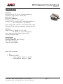
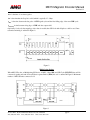
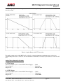
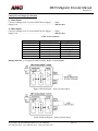
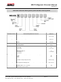
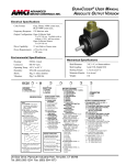
ME15 Magnetic Encoder Manual
Revision 1.1
Product Overview
The ME15 Magnetic Encoder is the newest addition to AMCI’s Encoder product line. The encoder is designed for
lower resolution and lower cost applications and provides 10 bits of resolution. The user has a choice either a SSI or 0
to 20mA, 4 to 20mA, 0 to 5V or 0 to 10V analog output. ME15’s small size, high reliability, IP67 protection rating and
low cost, make it an ideal replacement for potentiometers and small industrial encoders. Sturdy machined housing and
a high resistance to shock and vibration also make these encoders better able to withstand difficult environmental
conditions.
ME15 has two major components: A small diametrically polarized magnet and a custom ASIC which contains an array
of Hall sensors that generate a voltage when exposed to a magnetic flux field. The ASIC detects the change in
magnetic flux distribution as the magnet rotates above it delivers a voltage representing its angular position. The ASIC
cancels magnetic interference permitting it to operate in areas of high external fields. The encoder’s electronics
features a programmable device for converting the signals to a SSI-compatible bit stream.
The encoder is housed in an IP67 Size15 (1.5” dia) servo mount body with two options for shaft sizes - 1/4” and 6mm,
and two options for connections – through a 7-pin connector or built-in cable with flying leads of various lengths.
20 Gear Drive, Plymouth Industrial Park, Terryville, CT 06786
Tel: (860) 585-1254 Fax: (860) 584-1973 Web: www.amci.com
page: 1
ME15 Magnetic Encoder Manual
Revision 1.1
General Information
Important User Information
The products and application data described in this manual are useful in a wide variety of different applications.
Therefore, the user and others responsible for applying these products described herein are responsible for determining
the acceptability for each application. While efforts have been made to provide accurate information within this
manual, AMCI assumes no responsibility for the application or the completeness of the information contained herein.
Throughout this manual the following two notices are used to highlight important points.
WARNINGS tell you when people may be hurt or equipment may be damaged if the procedure is not followed
properly.
CAUTIONS tell you when equipment may be damaged if the procedure is not followed properly. No patent liability is
assumed by AMCI, with respect to use of information, circuits, equipment, or software described in this manual. The
information contained within this manual is subject to change without notice. UNDER NO CIRCUMSTANCES WILL
ADVANCED MICRO CONTROLS, INC. BE RESPONSIBLE OR LIABLE FOR ANY DAMAGES OR LOSSES,
INCLUDING INDIRECT OR CONSEQUENTIAL DAMAGES OR LOSSES, ARISING FROM THE USE OF ANY
INFORMATION CONTAINED WITHIN THIS MANUAL, OR THE USE OF ANY PRODUCTS OR SERVICES
REFERENCED HEREIN.
Standard Warranty
ADVANCED MICRO CONTROLS, INC. warrants that all equipment manufactured by it will be free from defects,
under normal use, in materials and workmanship for a period of [18] months. Within this warranty period, AMCI shall,
at its option, repair or replace, free of charge, any equipment covered by this warranty which is returned, shipping
charges prepaid, within one year from date of invoice, and which upon examination proves to be defective in material
or workmanship and not caused by accident, misuse, neglect, alteration, improper installation or improper testing. The
provisions of the “STANDARD WARRANTY” are the sole obligations of AMCI and excludes all other warranties
expressed or implied. In no event shall AMCI be liable for incidental or consequential damages or for delay in
performance of this warranty.
Returns Policy
All equipment being returned to AMCI for repair or replacement, regardless of warranty status, must have a Return
Merchandise Authorization number issued by AMCI. Call (860) 585-1254 with the model and serial numbers along
with a description of the problem. A “RMA” number will be issued. Equipment must be shipped to AMCI with
transportation charges prepaid. Title and risk of loss or damage remains with the customer until shipment is received
by AMCI.
24 Hour Technical Support Number
Technical Support, in the form of documents, FAQs, and sample programs, is available from our website,
www.amci.com. 24 Hour technical support is also available on this product. For technical support, call (860) 5851254. Your call will be answered at the factory during regular business hours, Monday through Friday, 8AM - 5PM
EST. During non-business hours, an automated system will ask you to leave a detailed message and the telephone
number that you can be reached at. The system will page an engineer on call. Please have your product model number
and a description of the problem ready before you call.
20 Gear Drive, Plymouth Industrial Park, Terryville, CT 06786
Tel: (860) 585-1254 Fax: (860) 584-1973 Web: www.amci.com
page: 2
ME15 Magnetic Encoder Manual
Revision 1.1
Table of Contents
Product Overview …………………………………………………………………………………1
Specifications ……………………………………………………………………………………...4
ME15 SSI Option………………………………………………………………………………….5
ME15 SSI Output Ordering Guide……………………………………………………...9
ME15 Analog Output Option………………………………………………………..……….…10
Analog Voltage Output …………………………………………………………………12
Analog Current Output…………………………………………………………………12
ME15 Analog Output Ordering Guide…………………………………………………13
Mechanical Dimensions………………………………………………………………………….14
Manual Revision History…………………………………………………………..…………….15
20 Gear Drive, Plymouth Industrial Park, Terryville, CT 06786
Tel: (860) 585-1254 Fax: (860) 584-1973 Web: www.amci.com
page: 3
ME15 Magnetic Encoder Manual
Revision 1.1
SPECIFICATIONS
Mechanical
Enclosure: Size 15 (1.5” dia) servo mount aluminum body;
Connections: 7-pin Connector or Cable style;
Shaft: 6mm or .25”
Max. Speed: 20,000 RPM;
Moment of Inertia: 1.75 * 10-5 oz-in-sec2
Starting Torque: 2 oz. in max @25° C (with standard shaft seal);
0.2 oz. in max @25° C (no shaft seal);
Shaft Loading: 10 lbs. radial/5 lbs. axial maximum shaft loading;
Bearing life: 2x10⁹ revolutions minimum at maximum shaft load;
Electrical
Supply Voltage: 5 – 30VDC (+/- 5%) for SSI,
20 – 30VDC (+/- 5%) for Analog Output;
Over voltage and reverse polarity voltage protected;
Power up setting time: 20ms;
Environmental
Protection Rating: IP67
Operating Temperature: -40 to +85 deg C
Shock: 50G, 11ms duration
Vibration: 20G, 5-2000 Hz
Output Versions Available
•
•
SSI
ANALOG OUTPUT
o Voltage Output: 0 – 5VDC or 0 – 10VDC;
o Current Output: 0 – 20mA or 4 – 20mA;
20 Gear Drive, Plymouth Industrial Park, Terryville, CT 06786
Tel: (860) 585-1254 Fax: (860) 584-1973 Web: www.amci.com
page: 4
ME15 Magnetic Encoder Manual
Revision 1.1
ME15 SSI OPTION
Supply Voltage……………………5 - 30VDC (+/- 5%)
Power Consumption……………….< 0.5W
Measuring Range……………….…360°.
Resolution/Code…………………..10 Bit / Binary
Position Accuracy…………………0.5°
Linearity……………………………< 0.5%
Repeat Accuracy…………………...< 0.1%
SSI Interface:
Clock Frequency………………….100 KHz – 1 MHz
Output Driver……………………..RS 485 (TIA/EIA Compliant)
Short circuit proof outputs:……….Yes ∗
∗ Short circuit to 0V (DC Return) or to output, when supply voltage is correctly applied.
The M15 SSI device has two options of operation: Standalone Option or Multiplexing Option. When M15 works as
Standalone SSI device, data is continuously read-out by simply applying SSI Clock signal with Enable line pulled low
(i.e. tied to the DC Return). When M15 works as Multiplexing SSI device, Enable line determines whether particular
M15’s input/output driver is enabled (Enable Input low) or disabled (Enable Input high). Only one unit at the time is
supposed to be enabled and all others disabled.
SSI Protocol
The serial data transmission timing is outlined in Figure 1: With the first falling edge of the clock (CLK) signal, data is
latched into the output shift register. Each subsequent rising CLK edge shifts out one bit data.
The serial word contains 16 bits. The first 10 bits D[9:0] are the absolute angular position data (MSB is clocked out
first). The subsequent 6 bits contain system information; about validity of data such as OCF (Offset Compensation
Finished), COF (Cordic Overflow), LIN (Linearity Alarm), Parity and Magnetic Field status (increase / decrease / out
of range) and they are used for diagnostic purposes only.
Figure 1: Synchronous serial interface with absolute angular position data
20 Gear Drive, Plymouth Industrial Park, Terryville, CT 06786
Tel: (860) 585-1254 Fax: (860) 584-1973 Web: www.amci.com
page: 5
ME15 Magnetic Encoder Manual
Revision 1.1
t INT is the time of one interrogation.
t M is the time that the Stop bit is valid, which is typically 15 – 20 µs.
t IDL is the time between the last pulse of CLK signal cycle and the first falling edge of the next CLK cycle.
t DO valid is time between rising edge of CLK and data output valid.
Optionally, if only absolute angular position data is needed, then SSI clock with 10 pulses could be used. Data
transmission timing is outlined in Figure 2:
Figure 2
Multiplexing Option
When M15 SSI works as Multiplexing SSI device, all M15’s Data (DO) and SSI Clock (SSI CLK) lines will be
connected together and each device will have separate Enable (ENn) line as it is outlined in Figure 3. Maximum
number of M15 SSI units connected is 32.
Figure 3
20 Gear Drive, Plymouth Industrial Park, Terryville, CT 06786
Tel: (860) 585-1254 Fax: (860) 584-1973 Web: www.amci.com
page: 6
ME15 Magnetic Encoder Manual
Revision 1.1
Enable lines have to be controlled in such way that only one M15 unit is enabled at time.
Figure 4: Timing for ENn lines
In a case that only one or a very few interrogations is needed during sampling time, then the ENn and CLK signal
synchronization is necessary and is outlined in Figure 5:
Figure 5: An example of one interrogation per sampling time
t SAMPLE is the time for which the device is enabled and interrogated
t EN_READY is the time between falling edge of ENn signal and the first falling edge of CLK signal.
20 Gear Drive, Plymouth Industrial Park, Terryville, CT 06786
Tel: (860) 585-1254 Fax: (860) 584-1973 Web: www.amci.com
page: 7
ME15 Magnetic Encoder Manual
Revision 1.1
ENn Voltage Range:
Enabled (Low) = 0 to 0.8VDC
Disabled (High) = 2 to 5VDC
Input Current: 10µA @5VDC for both High and Low states.
Timing Characteristics:
Symbol
MIN
tM
TYP
MAX
15 - 20
t ID L
UNIT
µs
50
µs
t DO valid
375
ns
t EN_READY
25
µs
t SHTDWN
5
µs
SSI Option Cable / Pin Assignment
Cable Style - Color
Red
Black
Green
Brown
Blue
Orange
White
Connector Style - Pin
1
2
3
4
5
6
7
Signal
+DC Input
DC Return
+CLK
-CLK
+DO
-DO
ENn
Mating connector: (sold separately) AMCI #: MS-9; Binder #: 99 0426 00 08
Figure 6: Block Diagram – SSI Output
20 Gear Drive, Plymouth Industrial Park, Terryville, CT 06786
Tel: (860) 585-1254 Fax: (860) 584-1973 Web: www.amci.com
page: 8
ME15 Magnetic Encoder Manual
Revision 1.1
AMCI ME15 Absolute SSI Rotary Shaft Encoder Ordering Guide
Part Number Character
Readily Available
Selections
Absolute SSI DuraCoder Selections
Mounting Style:
S = 1.5" Shaft style servo mount
Shaft Seal Type:
S = Shaft seal (IP67 rating)
S
Shaft seal
Shaft Diameter:
2 = 1/4"
6 = 6mm
2
1/4" Shaft
Output Type:
S = SSI
S
SSI
Output Scaling:
1 = binary
Angular Range:
K = 360° (This is the only option available on a ME15 with SSI output)
Direction:
P = CW increasing looking at the shaft
N = CCW increasing looking at the shaft
P
CW increasing
Connection Type:
E = End Connect Mating Connector (MS-9 mating connector sold separately)
FL = Integral Cable
E
End connector
Integral Cable Length
Specify the length in feet
Standard Lengths = 1.5’, 3’, 6’, and 10’
Blank if End Connector specified
20 Gear Drive, Plymouth Industrial Park, Terryville, CT 06786
Tel: (860) 585-1254 Fax: (860) 584-1973 Web: www.amci.com
S
Servo mount
1
Binary
K
360°
1.5'
page: 9
ME15 Magnetic Encoder Manual
Revision 1.1
ME15 - ANALOG OUTPUT OPTION
Supply Voltage…………………..20 – 30VDC (+/- 5%)
Power Consumption (No Load)…< 0.6W
Measuring Range………………...360°, 180°, 90°, 45°
Resolution……..…………………one part in 1024 voltage or current
Position Accuracy……………… 0.5° (360° measuring range)
Linearity………………………….< 0.5% of output range
Repeat Accuracy…………………< 0.1% of output range
There are four different angular ranges available to be select (factory preset): 45º, 90 º, 180 º, and 360 º. The analog
output response is linear for the selected range. For 45 º - and 90 º - modes, the slope is mirrored at 180 º. For the 180 º
- mode, it has a step response at 270 º. This allows the ME15 to be used in a variety of applications. In these three
modes, the output remains at its’ max and min values to avoid a sudden output change when the mechanical angle is
rotated beyond the selected analog range. In 360 º - mode, a jitter between max and min output value at the 360º point
is prevented due to a hysteresis.
The following diagrams show the output waveforms for the four angular ranges of an encoder ordered with CW
increasing output.
Figure 7: Angular Ranges with CW increasing
20 Gear Drive, Plymouth Industrial Park, Terryville, CT 06786
Tel: (860) 585-1254 Fax: (860) 584-1973 Web: www.amci.com
page: 10
ME15 Magnetic Encoder Manual
Revision 1.1
The following diagrams show the output waveforms for the four angular ranges of an encoder ordered with CCW
increasing output.
Figure 8: Angular Ranges with CCW increasing
The Analog output version of the ME15 can be ordered to output its minimum to maximum output over the four
Angular Ranges listed above. However, the next minimum to maximum cycle always begins at the start of the next full
turn.
Analog Voltage Output Specifications
0 – 5VDC Option
Current Consumption (No Load and 24VDC Power Supply)……25mA
Current Output……………………………………………………10mA max.
Output Load…………………….………………………………...500 Ohms min.
0 – 10VDC Option
Current Consumption (No Load and 24VDC Power Supply)…….25mA
Current Output…………………………………………………….10mA max.
Output Load……………………………………………………….1KOhm min.
20 Gear Drive, Plymouth Industrial Park, Terryville, CT 06786
Tel: (860) 585-1254 Fax: (860) 584-1973 Web: www.amci.com
page: 11
ME15 Magnetic Encoder Manual
Revision 1.1
Analog Current Output Specifications
0 – 20mA Option
Current Consumption (No Load and 24VDC Power Supply)…….35mA
Output Load……………………………………………………….500Ohm max.
4 – 20mA Option
Current Consumption (No Load and 24VDC Power Supply)…….35mA
Output Load……………………………………………………….500Ohm max.
Cable / Pin Assignment:
Cable Style - Color
Red
Black
Green
Brown
Connector Style - Pin
1
2
3
4
5
6
7
Signal
+DC Input
DC Return
Analog Output
Analog Output Return
N.C.
N.C.
N.C.
Mating connector: (sold separately) AMCI #: MS-9; Binder #: 99 0426 00 08
Figure 9: Block Diagram – Analog Voltage Output
Figure 10: Block Diagram – Analog Current Output
20 Gear Drive, Plymouth Industrial Park, Terryville, CT 06786
Tel: (860) 585-1254 Fax: (860) 584-1973 Web: www.amci.com
page: 12
ME15 Magnetic Encoder Manual
Revision 1.1
AMCI ME15 Absolute Analog Rotary Shaft Encoder Ordering Guide
Part Number Character
Readily Available
Selections
Absolute Analog DuraCoder Selections
Mounting Style:
S = 1.5" Shaft style servo mount
S
Servo mount
Shaft Seal Type:
S = Shaft seal (IP67 rating)
S
Shaft seal
Shaft Diameter:
2 = 1/4"
6 = 6mm
2
1/4" Shaft
Output Type:
V = Analog Voltage
C = Analog Current
Output Scaling:
If DuraCoder Type = V
1 = 0 to 5Vdc
2 = 0 to 10Vdc
V
Analog
V
2 = 0 to 10V
If DuraCoder Type = C
1 = 4 to 20mA
2 = 0 to 20mA
Angular Range:
C
1 = 4 to 20mA
K = 360° (This is the only option available on a ME15 with SSI output)
L = 180°
M = 90°
N = 45°
K
360°
Direction:
P = CW increasing looking at the shaft
N = CCW increasing looking at the shaft
P
CW increasing
Connection Type:
E = End Connect Mating Connector (MS-9 mating connector sold separately)
FL = Integral Cable with flying leads
E
End connector
Integral Cable Length
Specify the length in feet
Standard Lengths = 1.5’, 3’, 6’, and 10’
Blank if End Connector specified
20 Gear Drive, Plymouth Industrial Park, Terryville, CT 06786
Tel: (860) 585-1254 Fax: (860) 584-1973 Web: www.amci.com
1.5'
page: 13
ME15 Magnetic Encoder Manual
Revision 1.1
ME15 Mechanical Dimensions
20 Gear Drive, Plymouth Industrial Park, Terryville, CT 06786
Tel: (860) 585-1254 Fax: (860) 584-1973 Web: www.amci.com
page: 14
ME15 Magnetic Encoder Manual
Revision 1.1
Manual Revision History
Revision 0.0 was created 11/30/08 and was the initial release of the specifications.
Revision 1.0 was created on 1/30/09. Electrical Specifications revised.
Revision 1.1 was created on 4/29/09. Electrical Diagrams added.
20 Gear Drive, Plymouth Industrial Park, Terryville, CT 06786
Tel: (860) 585-1254 Fax: (860) 584-1973 Web: www.amci.com
page: 15